Embed Size (px)
Citation preview

B.G. Thomas (PI), Flow Dynamics and Inclusion Transport in Continuous Casting of Steel, NSF DMI Grant 01-15486, Final Report, 2005.
1
Flow Dynamics and Inclusion Transport in Continuous Casting of Steel
Overview of Activities
This report summarizes the activities pursued under NSF Grant DMI-01-15486, from October, 2001 to October, 2005, which is part of a long-term effort to develop and apply comprehensive models of the continuous casting of steel. This project was undertaken: 1) to develop quantitative computational models of transient flow of molten steel, superheat and inclusion behavior during the continuous casting of steel, and 2) to apply them to improve understanding and efficiency of inclusion particle removal in the process of continuous casting of steel slabs. Inclusion-related defects depend greatly on the flow dynamics in the mold pool, in addition to motion of the inclusions, collisions with other inclusions and bubbles, entrapment at the solidification front, heat transport in the liquid, top-surface slag-layer behavior, and the interfacial gap at the meniscus. These phenomena, shown in Fig. 1.1 are very difficult to measure in the steel plant, so this project first set out to develop better computational tools to understand these complex, inter-related phenomena. After validating each models with measurements, they were then applied to increase understanding of the continuous casting process.
Activities for this diverse multi-faceted research project proceeded along several related parallel tracks, which are divided here into seven different subprojects. Each subproject required a student to develop a computational model, to obtain experimental measurements, usually gained through working with researchers at the steel plants, and to apply the validated model to learn something of practical interest. The results of each subproject were presented by each student to steel industry representatives at the annual meetings of the Continuous Casting Consortium at the University of Illinois from Spring 2002 to Spring, 2005. In addition, the results formed the basis for over 50 (total) technical publications or presentations, including reports, conference presentations, journal papers, book chapters, graduate theses, and short courses to industry.
1) Transient fluid flow and particle transport (Q. Yuan)
1A) Computational issues
1B) Fluid flow and surface level fluctuations
1C) Transport and entrapment of small particles;
1D) Transport and entrapment of large particles
2) Parametric studies (L. Zhang)
3) Nucleation and growth models for alumina inclusions in molten steel (L. Zhang)
4) Inclusion removal via bubbles in the continuous casting mold (J. Aoki and L. Zhang)

B.G. Thomas (PI), Flow Dynamics and Inclusion Transport in Continuous Casting of Steel, NSF DMI Grant 01-15486, Final Report, 2005.
2
5) Flow and heat transfer in a molten flux layer; (B. Zhao)
6) Transient flow and superheat transport in continuous-cast steel slabs (B. Zhao)
7) Interface heat transfer and mold friction (Y. Meng) 1. Transient Fluid Flow and Particle Transport
The first part of this subproject investigates asymmetric flow in a full model of the process, consisting of both the complete nozzle (including the stopper rod, submerged entry nozzle and ports) and the mold region. Sample results are presented here from two simulations using the LES approach. First, the flow in a full-scale water model was simulated and compared with measurements. Then a simulation of the turbulent flow and inclusion transport in the corresponding full-scale steel caster is performed. The conditions were chosen to match conditions at the AK Mansfield thin slab caster shown in Fig. 1.2 and documented elsewhere [1, 2] where plant measurements were already available (132 x 984mm section, 1 m/min, 59 0C superheat).
The flow in the complex shaped nozzle is computed using LES (with approx. 630,000 cells), and the exit velocities were stored every 0.025 seconds for a period of 9.45 seconds. These were then used as inlet values to the two mold flow simulations, and recycled periodically. This two-step procedure greatly improved stability of the computation, while lowering the memory needed for a given simulation to less than 1.5 GB, (memory currently limits the problem size).
The time-dependent three-dimensional Navier-Stokes equations were solved using the Harlow-Welch fraction step procedure. Second order central differencing is used for the convection terms and the Crank-Nicolson scheme is used for the diffusion terms. The Adams-Bashforth scheme is used to discretize in time with second order accuracy. The pressure Poisson equation is solved using an Algebraic Multi-grid solver. No sub-grid model was used, while a dynamic model for the sub-grid scale kinetic energy has been developed for the use of continuing simulations. Computational grids consisting of 0.7 million and 1.3 million cells are used for these two mold region computations.
1A. Computational Issues in Simulation of Transient Flow in Continuous Casting
Unsteady three-dimensional turbulent flow and heat transport in the liquid pool during continuous casting of steel slabs has been computed using several different computational models, domains, grids, and inlet conditions. The most advanced computations employ a large-eddy simulation code, UIFLOW with a second-order central-differencing scheme, 1.6 million nodes and a realistic simulation domain including the complete submerged entry nozzle. The model has been validated in previous work through comparison with PIV measurements in caster water models, and with velocity and temperature measurements in an operating steel caster. The model equations, boundary conditions, and numerical discretization details are given elsewhere.[3, 4]
The present computations are compared with flow measurements in a full-scale water model and with heat flux measurements in a jet impingement test problem. Results are compared between model domains of the full caster with symmetric half-caster and two-fold symmetric quarter-caster simulations. The effects of thermal buoyancy and the solidifying steel shell walls are

B.G. Thomas (PI), Flow Dynamics and Inclusion Transport in Continuous Casting of Steel, NSF DMI Grant 01-15486, Final Report, 2005.
3
studied independently. The effect of different inlet conditions is investigated by comparing results including nozzle simulations that are both coupled and uncoupled with the mold domain and simplified nozzle geometry. The importance of the Sub-grid scale (SGS) model for treating the small turbulent eddies is investigated through simulations with and without the Horiuti SGS K model. A rigorous grid refinement study is undertaken, which indicates criteria for choosing the element size near the walls. Accurate heat transfer predictions are more difficult to attain than accurate velocities. Finally, comparisons are made with Reynolds-averaged approaches, including standard K-ε and low Re-number K- ε model computations of the same system. The relative advantages and disadvantages of the different flow simulation methods are evaluated.
To investigate the effect of mesh refinement, LES computations were performed on six different grids, (similar to that in Fig. 1.2) and containing 0.02, 0.08, 0.10, 0.20, 0.40, and 0.80 million cells. Assuming symmetry between the right and left sides, the computational domain was one half of the physical do-main. All simulations were performed with the SGS K-model and ignored buoyancy effects. The inlet conditions for these simulations were taken from a 100s half-nozzle simulation corresponding with the finest grid, stored every 0.001s.
The grids were all stretched with a factor of 1.01-1.03 to produce finer cells near the boundaries where they are most needed for accuracy, owing to the high local changes in gradient. This produced cell-center spacings from the wall at the critical region of jet impingement of 6mm, 3mm, 2.5mm, 2.5mm, 1.5mm and 1.5mm, for the 6 different grids respectively.
Water
Spray
Molten Steel Pool
Solidifying Steel Shell
Flux Rim
Submerged Entry Nozzle
Support Roll
Roll Contact
Ferrostatic Pressure
Bulging
Roll
Nozzle
Nozzle
copper mold
Liquid Flux
Air Gap
Flux Powder
jet
nozzle portargon
bubbles
Inclusion particles and bubbles
Resolidified Flux
Contact Resistances
Oscillation Mark
entrainment
CL
Figure 1.1 .Schematic of Flow Phenomena in Mold Region of Continuous Casting Process.
Figure 1.2. Schematic of the computational domain.
B.G. Thomas (PI), Flow Dynamics and Inclusion Transport in Continuous Casting of Steel, NSF DMI Grant 01-15486, Final Report, 2005.
4
1B) Flow Model Validation with Measurements The water model differs from the real steel caster in several respects important to fluid flow. First, the side walls of the water model, which represent the moving solidifying shell, are non-porous and stationary. Further, the water model has a flat bottom with outlet ports to represent the tapering molten pool of a curved casting machine. Figure 1.2 shows the computational domain of the steel caster, which includes these effects. Special source terms were added for both mass and momentum in order to satisfy the conditions on the moving boundaries of the domain, which represent the dendritic solidification front.
Having been validated, the flow model is next applied to investigate related phenomena. Although a critical first step, the flow field is not the primary interest of this project. Defects in the process are generated by the phenomena which accompany the dynamic flow field.
1C. Transport and Entrapment of Small Particles Another important consequence of the flow pattern in the mold is the transport of inclusion particles within the molten pool. Inclusions may eventually be removed harmlessly into the top slag layer, or they may become entrapped in the solidifying shell. Fundamental criteria have been developed for the capture of inclusions by a moving dendritic interface through engulfment or entrapment, considering together for the first time: critical interface velocity, particle size, and local cross-flow velocity. Small inclusions (<40 µm) are predicted to become surrounded by the dendrite arms and entrapped with little chance of “particle pushing”.
In this sub-project, Large-Eddy_Simulation models are developed to simulate the transient transport and entrapment of inclusion particles, using a Lagrangian approach based on previous computations of fluid flow in the continuous casting process [5]. Efforts focus on validation using measurements in both water models and analysis of actual steel samples. This section investigates the transport and capture of small inclusions (10µm and 40µm) in a thin-slab steel caster, as described in detail elsewhere [6].
Model Description The geometry and operating conditions of the thin-slab caster are given in Fig. 1.1 and Table I. Fluid flow and particle transport were computed in the model domain (Fig. 1.2) that includes the 1.11m submerged entry nozzle and the top 2.40m of a steel strand (Case 2-S). Three dimensional time-dependent turbulent fluid velocities were first obtained by solving the Navier-Stokes equations using large eddy simulations (LES) [5]. Special velocity boundary conditions [5] were applied to the fluid at the solidifying front in the steel caster to simulate the solidification effects. The transport of inclusion particles through this flow field was then modeled as follows.
Governing Equations: Particle transport was solved by integrating the following equations in a Lagrangian framework:
p
p
d
dt=
xv
[1]
( )( )0.6870
218
1 0.15Re (1 ) fp safp p
p pp p
d
dt md
ρν ρρρ
= + − + − +v F
v v g
[2]

B.G. Thomas (PI), Flow Dynamics and Inclusion Transport in Continuous Casting of Steel, NSF DMI Grant 01-15486, Final Report, 2005.
5
where:
g = (0, 0, 9.81m/s2) [3]
0Re
p pp
d
ν
−=
v v
[4]
( )1/ 2 1/ 22
01.61 ( )saff p pd μ ρ − ⎡ ⎤= − ×⎣ ⎦F ω v v ω [5]
and = ∇×ω v [6]
The three terms on the RHS of Eq. [2] are due to the forces of drag (for Rep<800), buoyancy (due to density difference) and Saffman lift (due to shear velocity gradients) for spherical particles. Rep is the Reynolds number for creeping flow, based on the small difference between the fluid and particle velocities.
Initial and Boundary Conditions: Inclusions were introduced into the computational domain at the local fluid velocity. Their initial positions were chosen randomly in the edges of a cylindrical region in the tundish above the submerged entry nozzle. The results of the separate simulation of fluid flow and particle trajectories in the nozzle itself were used to determine the particle locations in the nozzle outlet port planes for the strand simulation. Inclusions touching the top surface were assumed to be removed.
Modeling of Particle Capture by the Solidification Front: In a steel caster, inclusions may be trapped when they touch the walls, which represent the solidification front. The capture of inclusions by an advancing solidification front involves complex phenomena which have been investigated in many previous studies, which have been reviewed elsewhere [7]. Particles that are smaller than the dendrite arm spacing are captured if they touch the interface.
The results presented here focus on particles smaller than the PDAS which can easily enter in between primary dendrite arms and become entrapped with little chance of being pushed away regardless of solidification front velocity [7]. Measurements on the caster of interest here (Fig. 2) [1] show that the PDAS is smallest near the top surface (about 50μm) and increases along the casting direction as the solidification rate slows. Thus, this section investigates 10μm and 40μm particles which are predicted to become entrapped instantly upon touching the solidification front.
Solution Procedure: The particle transport equations were integrated using the fourth order Runge-Kutta method [8]. Particle velocities and displacements were solved at every time step after the fluid velocity field was solved. The local fluid velocity in the drag and lift terms of Eq.[2] was interpolated from the nearest neighbor cells using a second order scheme [8]. Due to the low volume fraction of impurity inclusions for the continuous casting process (~0.01% for a typical steel with 30ppm oxygen), one-way coupling was employed, which neglects the modification of fluid turbulence by the particles. The removal and capture criteria were tested whenever a particle crossed a domain boundary.
Computational Details: In this work, the transport and capture of four groups of 10,000 small inclusions, with two different sizes (10µm and 40µm) and two different densities (2700 kg/m3 and 5000 kg/m3), were simulated in an thin slab steel caster (Fig. 1.2). These inclusions could

B.G. Thomas (PI), Flow Dynamics and Inclusion Transport in Continuous Casting of Steel, NSF DMI Grant 01-15486, Final Report, 2005.
6
represent entrained mold slag or alumina particles, with varying amounts of entrained steel filling internal voids and thus raising its density. The computational domain has two portions. The nozzle domain includes part of the bottom of the tundish and the entire 1.11m long trifurcated submerged entry nozzle. The strand domain includes the top 2.4m of the molten pool in the mold and strand. This 2.4m computational domain is part of the 3m straight section of the caster. In contrast with the water model, the steel caster has no solid bottom wall. The internal liquid pool domain shape was curved to account for the shell, and had mass flowing through it to represent solidification. The shell thickness increases from 0 at the meniscus to 26mm (wide face) or 25mm (narrow face) at domain exit [5]. The two different densities assigned to the particles represent different fractions of molten steel in the inclusion. [9] The 40,000 computed particles were introduced into the three nozzle port outlet planes over 9s (33-42s of the fluid simulation). More information on casting conditions, material properties and computational parameters on both cases is given in Table I. Methodologies were implemented to optimize the time step size and computational cost, according to the particle response time. Both the flow simulations (1.3M cells) and the transport of 40,000 particles took about 29.2 CPUs per fluid time step (0.001s).
Table I. Properties and conditions of the particle simulation in the thin-slab steel caster.
Parameter/Property Thin-Slab Caster Full-Scale Water Model
Mold Width (mm) 984 1830 Mold Thickness (mm) 132 238 Water Model Length (mm) - 2152 Mold Length (mm) 1200 - Domain Width (mm)
- top - bottom
984 934.04
915 915
Domain Thickness (mm) - top - bottom
132 79.48
238 238
Domain Length (mm) 2400 2152 Nozzle Port Height × Thickness (mm × mm) 75 × 32 (inner bore) 51×56 Bottom nozzle Port Diameter (mm) 32 - SEN Submergence Depth (mm) 127 150 Casting Speed (mm/s) 25.4 15.2 Fluid Dynamic Viscosity (m2/s) 7.98 × 10⁻⁷ 1.0 × 10⁻⁶ Fluid Density (kg/m3) 7020 1000 Particle Density (kg/m3) 2700 and 5000 988 Particle Diameter (μm) 10 and 40 3800
Model Validation in a Full-Scale Water Model The computational model of particle transport was first applied in a full-scale water model, where measurements on particle removal are available. [10] In the experiments, around 8,000-30,000 elliptical disk-shaped plastic beads were injected into the liquid pool with water through the nozzle over a few seconds. [10] The density and size of the beads were chosen to aid

B.G. Thomas (PI), Flow Dynamics and Inclusion Transport in Continuous Casting of Steel, NSF DMI Grant 01-15486, Final Report, 2005.
7
visualization while approximating the vertical terminal velocity expected of typical 300μm inclusions in liquid steel. [10] To model the removal of inclusion particles to the top surface, a screen was positioned near the top surface and the SEN to trap plastic beads as they flowed across the top surface towards the SEN and headed downwards. The experiments were repeated at least five times and the average inclusion removal fraction by the screen was reported elsewhere. [10]
In the simulation, the fluid velocity field was solved using LES [5]. The capture of particles by the screen was modeled by summing the particles that crossed the screen from the top. The screen influenced neither the fluid velocity field [5] nor the particle transport. The particles were divided into five groups of 500 particles and another six groups of 2,500 particles, in order to investigate statistical variations and the effect of the number of particles. The particles were injected into the nozzle ports over a realistic time interval.[6]
The particle fractions removed by the screen for the 2,500 and 500 particle groups are presented in Table II, and are also compared with measurements. The average removal fractions for both groups agree with experiments within ±5%. However, the removal fraction varies greatly between groups, especially for the first 10s after particles enter the mold. This is reflected by the
standard deviation, (σu= ( )∑=
−N
imeani Nuu
1
2 / ) which decreases from 5.5% (500 particle groups)
and 4.8% (2,500 particle groups) for 0-10s to 2.9% and 1.4% for 10-100s.
Simulation of Particle Transport and Entrapment in the Thin-Slab Caster After examining the accuracy of this computational model of particle transport in a standard-slab water model, it then was applied to investigate the transport and capture of small inclusions in the actual thin slab steel caster (Fig. 1), in which a trifurcated nozzle is used [1, 2, 6]. The fluid velocities were obtained from LES [5] and conditions are given in Table I.
Inclusion Capture in Solid Steel Slabs after a Sudden Burst: A sudden “burst” of inclusions entering the liquid pool may occur in the continuous casting process during upstream events such as temporary vortexing, release of a nozzle clog or other upset. [11, 12] The particle study in this work can be considered as a 9s burst of 40,000 inclusions entering the molten steel pool. By relating the total time traveled by each particle with the casting speed and its capture position, the distance of each of the 51% of the captured particles down the final solidified slab was calculated. The final positions of these particles are shown in Fig. 4, as transverse projections onto the wide and narrow faces. Zero on the vertical axis points to the slice of the shell which was at the meniscus at the time when the first particle entered the strand (33.0s). All slices continuously moved downward with the whole shell at the casting speed during the process. The shadowed length in Fig. 4 is the distance travelled by the strand during the 9s burst.
Total Oxygen Distribution in Thin Steel Slabs Total oxygen content in the final solidified steel was calculated based on the computed positions and times of particle capture. The distribution of particles captured under a condition of continuous injection is found from the results in the previous section by assuming the 9s burst of particles to repeat every 9 seconds. The molten steel was assumed to exit the nozzle with a steady oxygen content of 10ppm (by mass), from pure alumina (Al2O3) inclusions. The oxygen distribution in a typical cross section through the solidified slab was obtained by first projecting the entire computational domain [6] onto a transverse x-y section to define a 2-D grid of 3-D

B.G. Thomas (PI), Flow Dynamics and Inclusion Transport in Continuous Casting of Steel, NSF DMI Grant 01-15486, Final Report, 2005.
8
cells. The cell transverse dimensions, Δx and Δy, vary from 0.5mm to 6mm according to distance beneath the strand surface. The cell vertical dimension, Δz, is the length cast, 228.6mm, during the 9s burst. The total oxygen concentration in each cell, CO, was calculated by dividing the mass of oxygen in all particles entrapped in that cell by the cell mass (including both cast steel and particles):
( )o
p
p
(48/102) MC
xΔyΔz (1 / )Mpρ ρ ρ=
Δ + − [7]
where Mp =
CN
i=1
3d
6p pπ ρ
∑ and Nc are the total mass and number of particles entrapped in the cell.
The central region representing the area of the liquid pool at the domain exit was treated as a single large cell. This cell would contain all of the inclusions that exited the domain.
The number of particles entrapped in each cell, NC, was obtained by summing the contributions from a series of 9s bursts. Each burst represents the contribution from a different time interval. The entrapment locations for each burst are obtained by translating the results in Fig. 4 vertically by Δz*i. The burst number i is an integer with a minimum value from the z coordinate of the last particle captured (-5.2m from Fig. 4) divided by Δz. The maximum i value is the domain bottom coordinate (+1.9m) divided by Δz. The final particle distribution is obtained from the sum of the entrapment distributions from each value of i within this range.
1B Summary Lagrangian computations of particle transport during continuous casting of steel slabs were performed in this study. Time-dependent fluid velocity fields obtained from LES were employed in the particle computations. The computational model was applied to simulate the transport and capture of small (10µm and 40µm) inclusions in a thin slab steel caster.
Table I. Properties and conditions of the particle simulation in the thin-slab steel caster.
Parameter/Property Thin-Slab Caster Full-Scale Water Model
Mold Width (mm) 984 1830 Mold Thickness (mm) 132 238 Water Model Length (mm) - 2152 Mold Length (mm) 1200 - Domain Width (mm)
- top - bottom
984 934.04
915 915
Domain Thickness (mm) - top - bottom
132 79.48
238 238
Domain Length (mm) 2400 2152 Nozzle Port Height × Thickness (mm × mm) 75 × 32 (inner bore) 51×56 Bottom nozzle Port Diameter (mm) 32 - SEN Submergence Depth (mm) 127 150

B.G. Thomas (PI), Flow Dynamics and Inclusion Transport in Continuous Casting of Steel, NSF DMI Grant 01-15486, Final Report, 2005.
9
Casting Speed (mm/s) 25.4 15.2 Fluid Dynamic Viscosity (m2/s) 7.98 × 10⁻⁷ 1.0 × 10⁻⁶ Fluid Density (kg/m3) 7020 1000 Particle Density (kg/m3) 2700 and 5000 988 Particle Diameter (μm) 10 and 40 3800
1D. Transport and Entrapment of Large Particles
The Large-Eddy_Simulation models of this project that were validated numerically (see previous section) were further extended to simulate the transient transport and entrapment of inclusion particles, based on previous computations of fluid flow in the continuous steel casting process.[5] A Lagrangian approach was developed to simulate the transport of large groups of particles through the transient flow fields. The same computational model, domain, initial and boundary conditions were used as for small particles, except for the capture criterion by the solidification front.
1D.1.3 Modeling of Particle Capture by the Solidification Front: Particles that reach the mushy zone front may be trapped by the solidifying shell or repulsed back into the molten steel flow. The outcome between capture and pushing depends on many phenomena, including the morphology of the solidifying dendrites, the interfacial surface tension governed by the concentration boundary layer of the interfacial active solute (especially the sulfur content), the boundary layer velocity profile, and the particle velocity, size, density and morphology. The flow velocities close to the dendritic interface can be estimated from the LES model during the simulation. However, accurate resolution of the dendrite shape and the concentration boundary layer is computationally prohibitive. To overcome this problem, a novel, but simple criterion for particle pushing and capture has been developed in this work, based on a force balance analysis.
Particles Smaller than the PDAS: Particles smaller than the primary dendrite arm spacing (PDAS), (i.e. 2Rp<PDAS), can easily flow in between the dendrite arms without major disturbance of their growth. Larger particles cannot do this. If the particle is smaller than the PDAS, it will be surrounded by the growing dendrites, and it will be captured whenever it reaches the solidification front. The attractive force generated by the surface energy gradient further encourages this to happen. Previous experimental studies [13] in quiescent solidification systems confirm that particles smaller than the PDAS are entrapped, even when the dendrite growth speed is much lower than the critical value for particle pushing. Therefore, a particle smaller than the PDAS is modeled as being captured by the shell whenever it touches a computational boundary representing a mushy zone (solidification) interface.
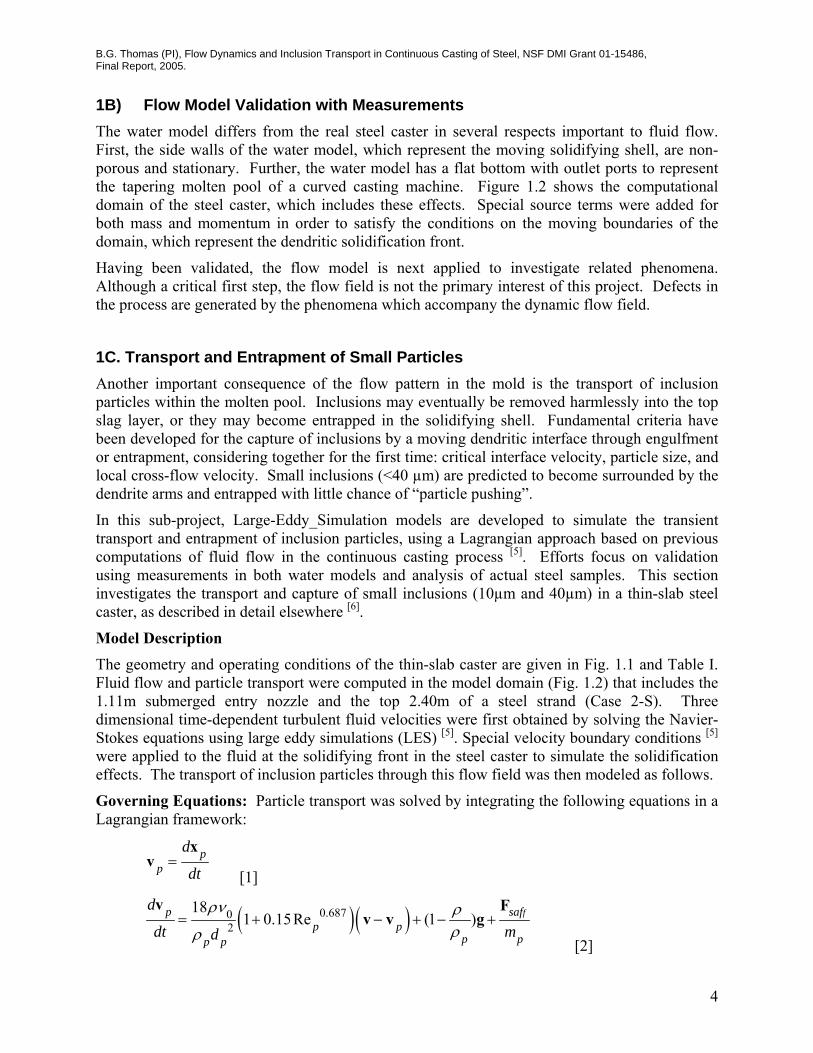
Particles Larger than the PDAS: Unlike smaller particles, particles larger than the local PDAS cannot fit between the dendrite arms. Figure 1.16 shows a typical dendritic front shape.[14] As depicted in Figure 5, a spherical particle of alumina or slag transported to the solidification front contacts the solidifying dendrites through a thin film of liquid steel at the critical distance. If all of the forces acting on the particle are in stable equilibrium, then it will eventually be captured by the solidifying shell as the dendrites grow to surround it. The particle will avoid being captured if the net force acting in the solidification direction push it away from the interface, or if the net force acting across the dendrite front causes it to rotate away. These conditions are checked by considering the balance of the ten different forces which act on the particle in the boundary layer
B.G. Thomas (PI), Flow Dynamics and Inclusion Transport in Continuous Casting of Steel, NSF DMI Grant 01-15486, Final Report, 2005.
10
region, including the bulk hydrodynamic forces (lift FL, pressure gradient, stress gradient, Basset, and added mass forces), transverse drag force FD, (caused by fluid flow across the dendrite interface), gravity (buoyancy) force FB, and the forces acting at the interface (Van der Waals interfacial force FI, lubrication drag force FLub, and surface energy gradient force FGrad).
FD: Drag force; FGrad: Surface energy gradient force; FI: Van der Waals interfacial force; FLub: Lubrication drag force; FL: Lift force; FB: Buoyancy force; FN: Reaction force; Ff: Friction force.
Fig.1.16. Illustration of forces acting on a particle in front of solidifying dendrites.
The pressure gradient, stress gradient, Basset, and added mass forces are negligible because they are found to be small (<15% of the buoyancy force) in the bulk region, and are expected to be even smaller in the boundary layer. The condition of particle pushing or capture is determined through the following procedure:
Step 1: If the component of the total force (FTot) acting on the particle in the solidification direction (χ in Figure 5) is larger than zero, then the particle will be pushed away from the interface. This escape criterion is expressed as follows:
( ), , 2 cos 0Tot L D Lub Grad IF F F F F Fχ χ θ= − − − − > [7]
where: ( )
0.5PDAS/sinp d
acrR r
θ⎡ ⎤
= ⎢ ⎥+⎢ ⎥⎣ ⎦
[8]
Otherwise, check if the forces on the particle are large enough to avoid entrapment by pushing it along the interface. Step 2: If FTot,χ ≤ 0, then the forces acting in η direction (across the solidification front) push the particle against a dendrite arm, causing a reaction force (FN,1 or FN,2) and a friction force (Ff,1 or Ff,2) at the contact point, as shown in Figure 5. If furthermore, the net forces rotating the particle about the contact points push it towards the dendrites, then the particle will not move and it will eventually become surrounded by the growing interface and captured. Specifically, capture occurs by this criterion if one of the following two conditions holds:
(1) If the buoyancy (FB) and the η component of the drag (FD,η) are in the same direction and:
( )( )
, ,
ub
( )cos sin
sin 2D B L
L Grad I
F F F F
F F Fη η χθ θ
θ
+ + −
≤ − − [9] (2) If the buoyancy (FB) and the η component of the drag (FD,η) are in opposite directions,
and either:
ξ
η

B.G. Thomas (PI), Flow Dynamics and Inclusion Transport in Continuous Casting of Steel, NSF DMI Grant 01-15486, Final Report, 2005.
11
( )( )
,
ub
( ) cos sin
sin 2D B L
L Grad I
F F F F
F F Fη χθ θ
θ
− + −
≤ − −, if ,D BF Fη ≥
or [10] ( )
( ),
ub
( ) cos sin
sin 2B D L
L Grad I
F F F F
F F Fη χθ θ
θ
− + −
≤ − −, if ,B DF F η>
[11] If neither inequality in step 2 is satisfied, then the particle will escape by rotating about a dendrite tip away from the solidification front and drifting back into the flow. These equations, based on a two-dimensional balance, were found to represent an intermediate case between the variety of conditions that are possible when the full three-dimensional balance was calculated, as given elsewhere.[15]
The primary dendrite arm spacing needed for this analysis is found from measurements conducted on cast steel, and the dendrite tip radius (rd) is fitted from corresponding relations.[16] Calculations show that the Van der Waals interfacial force, the lubrication drag force and the surface energy gradient force are only important when the particle is very close to the solidification interface. Therefore, they can be neglected in the Lagrangian particle transport simulations. These forces are important, however, for evaluating the capture criterion to predict the fate of a particle when it touches a computational boundary representing a mushy zone front.
The results presented previously considered particles smaller than the PDAS (50-140 μm) which can easily enter in between primary dendrite arms and become entrapped with little chance of being pushed away regardless of solidification front velocity.[7] This report focuses on larger particles (100, 250, and 400μm in diameter), which are much more difficult to capture, especially when there is a large transverse velocity.
1D.1.4 Solution Procedure: The particle transport equations were integrated using the fourth order Runge-Kutta method.[8] Particle velocities and displacements were solved at every time step after the fluid velocity field was solved. The local fluid velocity in the drag and lift terms of Eq.[2] was interpolated from the nearest neighbor cells using a second order scheme.[8] Due to the low volume fraction of impurity inclusions for the continuous casting process (~0.01% for a typical steel with 30ppm oxygen), one-way coupling was employed, which neglects the modification of fluid turbulence by the particles. The removal and capture criteria were tested whenever a particle crossed a domain boundary.
1D.2 Capture Criterion Model Validation: The particle capture model was tested by applying it in simulations of several different experimental systems where particle capture was measured. Firstly, the model predictions of the critical velocity of the solidification front for the transition from particle pushing to particle capture were compared with measurements of alumina particles in quiescent solidifying liquid steel [17] and zirconia particles in quiescent solidifying aluminum melt.[18] Simulations were then conducted to reproduce the results of the capture or flow of PMMA particles in solidifying water with a tangential (cross) flow across the interfacial front.[19,
20] Both system produced reasonable results, as described in detail elsewhere.[15]
1D.3 Predicted Critical Cross-Flow Velocities in Continuous Steel Caster: Using the validated particle-capture criterion, the critical velocities of the flow relative to the downward moving shell for the capture of slag spheres were computed for typical conditions in a steel caster. The flow was assumed to be vertical (upwards or downwards) across a horizontally-

B.G. Thomas (PI), Flow Dynamics and Inclusion Transport in Continuous Casting of Steel, NSF DMI Grant 01-15486, Final Report, 2005.
12
growing solidification front, such as encountered near the narrow face in the continuous casting mold region.
1D.4 Particle Transport, Removal and Capture in the Thin-Slab Caster: The complete LES model with particle transport and capture criterion was then applied to simulate the transport and capture of three groups of 10,000 inclusions, with 2700 kg/m3 density and three different sizes (100, 250, and 400μm) in the thin slab steel caster. These inclusions could represent entrained mold slag or alumina particles that entered the mold through the nozzle over a 9s interval. The computational domain has two portions. The nozzle domain includes part of the bottom of the tundish and the entire 1.11m long trifurcated submerged entry nozzle. The strand domain includes the top 2.4m of the molten pool in the mold and strand. This 2.4m computational domain is part of the 3m straight section of the real caster. The internal liquid pool domain shape was curved to account for the shell, and had mass flowing through it to represent solidification. The shell thickness increases from 0 at the meniscus to 26mm (wide face) or 25mm (narrow face) at domain exit, according to measured profiles.[5]
Elastic re-bound was assumed when a particle hit the plastic wall of the water model or the outer surface of the nozzle in steel casters. Particles touching the top surface were assumed to be safely removed by the slag layer. The particle capture criterion was tested each time a particle touched a boundary representing the solidifying shell. If the result was particle pushing, then the particle was artificially forwarded into the fluid by a distance of 5% particle radius. More information on casting conditions, material properties and computational parameters on both cases is given in Table 1.5. Methodologies were implemented to optimize the time step size and computational cost, according to the particle response time. Both the flow simulations (1.3M cells) and the transport of 30,000 particles took about 29.2 CPUs per fluid time step (0.001s). Further details of the simulations are given elsewhere.[3, 4, 15]
1D.4.1 Particle Injection through nozzle: After demonstrating the accuracy of this computational model of particle transport in a standard-slab water model, [4], and applying it to investigate the transport and capture of small inclusions in the actual thin slab steel caster[1, 2, 6], it was next applied to investigate the transport, removal and entrapment of large inclusions. The fluid velocities were obtained from LES [5] and conditions are given in Table I.
1D.4.2 Slag entrainment from top surface: During the actual continuous casting process, fingers of the liquid slag layer may be emulsified into the liquid steel from the top surface mold slag layer and broken into spheres by the flow. This is an important alternative source of mold slag inclusions, in addition to those entering the nozzle from upstream. To model this, a computation was conducted where three groups of 4,000 particles with sizes of 100μm, 250μm and 400 µm entered the domain near the center of the top surface, where such emulsification most likely occurs. The particles were injected computationally over 1.8s into two symmetrical 20mm×6mm×7mm(x×y×z) volumes located just below the top surface. The height of the two volumes was chosen based on the measured steel-slag interface profile.[4]
1D.5 Conclusions: Lagrangian computations of particle transport during continuous casting of steel slabs were performed in this study, based on time-dependent fluid velocity fields obtained from LES. Particle entrapment by a solidification front depends on many factors including the particle size and density, transverse fluid velocity, sulfur concentration gradient, solidification front velocity, and primary dendrite arm spacing. A new capture criterion based on a balance of

B.G. Thomas (PI), Flow Dynamics and Inclusion Transport in Continuous Casting of Steel, NSF DMI Grant 01-15486, Final Report, 2005.
13
the important forces acting on a particle near a solidification front has been developed, validated with test problems and applied to simulate particle capture in a steel continuous caster.
Table 1.5. Properties and conditions of the particle simulation in the thin-slab steel caster.
Parameter/Property Value Mold Width (mm) 984 Mold Thickness (mm) 132 Mold Length (mm) 1200 Domain Width (mm)
- top - bottom
984 934.04
Domain Thickness (mm) - top - bottom
132 79.48
Domain Length (mm) 2400 Nozzle Port Height × Thickness (mm × mm)
75 × 32 (inner bore)
Bottom nozzle Port Diameter (mm) 32
SEN Submergence Depth (mm) 127
Casting Speed (mm/s) 25.4 Fluid Dynamic Viscosity (m2/s) 7.98 × 10⁻⁷
Fluid Density (kg/m3) 7020 Particle Density (kg/m3) 2700
Particle Diameter (μm) 100, 250 and 400
2. Parametic Studies: Effect of Nozzle Geometry on Inclusion Entrapment
Inclusion removal is affected by many parameters which affect the flow pattern in the mold cavity, including the nozzle and mold geometry, submergence depth, steel flow rate, argon injection rate, electromagnetic stirring, and flux layer properties. Changing nozzle geometry is an easy and inexpensive way to optimize the fluid flow in the mold. Technologies to improve fluid flow and inclusion removal involving the Submergence Entry Nozzle (SEN) include the nozzle port angle, introduction of flow directors that create swirl, multiple outlet ports, throttling plates with oval offset bore, and internal horizontal steps to introduce turbulence. Parametric studies were performed using multiphase flow in a water model, [21-23] and using computational modeling. The effect of nozzle port angle and the step nozzle technique [24] are investigated here using computational modeling.

B.G. Thomas (PI), Flow Dynamics and Inclusion Transport in Continuous Casting of Steel, NSF DMI Grant 01-15486, Final Report, 2005.
14
Steady flow in the strand of the continuous caster was simulated with a 3-D finite-difference computational model using the standard k-epsilon turbulence model in Fluent [6, 25]. Inclusion trajectories are calculated by integrating each local velocity, considering its drag and buoyancy forces. The “random walk” model is used to incorporate the effect of turbulent fluctuations on the particle motion. As boundary conditions for the particle motion, particles escape at the top surface and the open bottom, are reflected at the symmetry plane, and are entrapped when they touch the wide faces and narrow faces, which represent the dendritic solidification front. This entrapment condition was shown to be valid for particles smaller than the primary dendrite arm spacing [7]
The effect of steps in SEN and the outport angle of SEN on the fluid flow and particle motion in the mold is investigated. The casting conditions and parameters are shown in Table 2.1. The results are compared with industrial measurements, and conclusions regarding optimal mold operation are obtained.
Table 2.1. Casting conditions and parameters
Parameters Value Inlet port size ( width×height) (m×m) 0.065×0.080 Nozzle angle Down 15o, up 15o, zero Submergence depth (m) 0.3 Domain height/width/thickness (m) 2.55/1.3/0.25 Average inlet flow rate (half mold) (m3/s) 0.00325 Casting speed (m/min) 1.2 Fluid density (kg/m3) 7020 Fluid kinetic viscosity (m2/s) 0.954×10⁻⁶ Particle density (kg/m3) 5000 Particle diameter (μm) 49, 225 Inlet condition Nozzle simulation result Gas flow rate None Turbulence model k-ε, by Fluent Inclusion motion model Random walk model, Fluent, 80 tries, 16000
inclusions Boundary condition for inclusions Escape from top surface and open bottom,
trapped at narrow and wide face walls
3. Nucleation and Growth Models for Inclusions in Molten Steel Inclusion distribution computations require knowledge of the size distribution of particles entering the caster. The size distribution may be important to inclusion entrapment, and the size of captured inclusions is crucial to final steel quality, as defects increase with the size of non-metallic inclusion clusters. Previous work has used measured size distributions as the initial condition [9]. As part of this project, a fundamental model has been developed to predict the size distribution of indigineous inclusions in low carbon steels deoxidized with aluminum.

B.G. Thomas (PI), Flow Dynamics and Inclusion Transport in Continuous Casting of Steel, NSF DMI Grant 01-15486, Final Report, 2005.
15
Inclusions arise from many sources, including deoxidation, reoxidation, slag entrapment, chemical reactions, and exogenous inclusions. Inclusion evolution and removal is affected by diverse complex phenomena, including deoxidant quantity, composition, and morphology, vessel geometry, transport by turbulent flow, interfacial tension, diffusion coefficient, the initial oxygen content, collisions with both bubbles and other particles, reoxidation, temperature, and properties of the slag layer and vessel walls where inclusions may be removed or generated.
A computational model based on classic homogenous nucleation theory, thermodynamic analysis and numerical simulation, has been developed to predict of the nucleation and growth of the alumina size distribution in the molten steel, including the effects of Ostwald ripening, Brownian collision and turbulent collision. The model was tested by applying it to aluminum deoxidation of a typical steel-oxygen refining-ladle system.
It is best to start the model from nucleation, in order to avoid uncertainties in initial conditions. There are serious computational issues involved in solving the classic population balance equation of inclusions. These are the computation time and the array limit for memory storage. Because the model is being designed to simulate nucleation (concerned with individual molecules with sizes on the order of nanometers) up to collision of real particles (on the order of microns), the particle size range varies over 3 orders of magnitude, and contains from 1 to ~1013 molecules per particle. Using classic population balance equation of inclusions with a simple linear scale becomes prohibitive for this real system. To make this difficult problem feasible, a simplified model that can accurately handle varying size ranges ⎯ Size Group Model ⎯ is employed. In this model, the inclusions are divided into groups (group number k ) with average particle volumes related by the following ratio:
Vk
k RVV
=−1 [8]
where 2<RV<3 with 2.5 a typical value. The method can be developed for other choices of RV, but the following equations change slightly. Considering the critical size group jc for a stable particle, the evolution equations become:
Cjj <≤2 (namely nucleation)
jjjj
j
Djj
j
VV
NAVV
NNdt
dN 111 αβ −=
[9]
Cjj ≥ (namely growth)
( ) ( )
( ) ( )
1
2
111
1
1111,11,11.1
1
1
max
jjjj
k
Dij
j
jkkj
Bkj
Tkjjkjk
j
jjj
Bjj
Tjjjj
j
k j
kk
Bkj
Tkjkjj
j
VVNA
VVNN
NN
VV
NNVV
NNdt
dN
αβ
ββφδ
ββφββφ
−+
++−
++⎟⎟⎠
⎞⎜⎜⎝
⎛+=
∑
∑−
=
−−−−−−−−−
−
=
[10]

B.G. Thomas (PI), Flow Dynamics and Inclusion Transport in Continuous Casting of Steel, NSF DMI Grant 01-15486, Final Report, 2005.
16
where D
iβ is The rate constant for pseudo-molecule diffusion, Bijβ represents Brownian collision
and Tijβ represents turbulent collision, based on Saffman’s model [32].
According to classical homogenous nucleation theory, the critical radius of nucleus Cr is
Π≡
ln2
RTVr m
Cσ
. [11]
If Crr > , nucleation occurs, and stable particles precipitate and start to grow. According to Eq.[11], the critical size of nucleus decreases with increasing supersaturaion Π and decreasing surface tension. If jc is the critical group number, beyond which nucleation occurs, jc can be represented by
⎟⎟⎠
⎞⎜⎜⎝
⎛Π
+=ln
12ln
ln31
1RTrV
Rj m
vc
σ
(5)
The supersaturation of free Al2O3 molecules, Π, is represented by
eqNN
,1
1≡Π, [12]
where N1,eq=2.634×10²³ m–3 corresponds to 3ppm dissolved oxygen in steel at equilibrium. The total number of Al2O3 molecules including those in nucleated inclusions (NS), which is a function of dimensionless time, represented by Eq.[12] from the calculation of aluminum dissolution and diffusion in molten steel, which defines how fast the Al2O3 molecules appear and disperse in the liquid steel after the deoxidizer-Al is added.
⎥⎦
⎤⎢⎣
⎡⎟⎟⎠
⎞⎜⎜⎝
⎛−−=
10exp0.1100
** tN S
, [13] This equation was used in modeling inclusion evolution in a typical ladle [33], where measurements were available. The vessel was a 50 tonne ladle of low-carbon steel refined in an ASEA-SKF furnace.[34] The total oxygen before adding aluminum is around 300 ppm and the final free oxygen is about 3 ppm, which corresponds to a 46kg aluminum addition. The delay constant K was assumed to be 0.1. [35] The ladle had 2.3m diameter and 1.7m depth, which corresponds to a turbulent energy dissipation rate in the melt of 0.01224 m2/s3 (856.8 erg/cm3s). Predictions were made of nucleation, evolution of the inclusion size distribution, and ladle mixing behavior. The results revealed guidelines for ladle operating practice.
4. Inclusion Removal by Bubble Flotation in Continuous Casting Mold
Fundamentally-based computational models are developed to quantify the removal of inclusions by bubbles during the continuous casting of steel. First, the attachment probability of inclusions on a bubble surface is investigated based on fundamental fluid flow simulations, incorporating

B.G. Thomas (PI), Flow Dynamics and Inclusion Transport in Continuous Casting of Steel, NSF DMI Grant 01-15486, Final Report, 2005.
17
the turbulent inclusion trajectory and sliding time of each individual inclusion along the bubble surface as a function of particle and bubble size. Then, the turbulent fluid flow in a typical continuous casting mold, trajectories of bubbles and their path length in the mold are calculated. The change in inclusion distribution due to removal by bubble transport in the mold is then calculated based on the computed attachment probability of inclusion on each bubble and the computed path length of the bubbles. In addition to quantifying inclusion removal for many different cases, the results are important to estimate the significance of different inclusion removal mechanisms.
4.1 Inclusion-Bubble Interactions in Molten Steel The attachment process of an inclusion to a gas bubble in the molten steel proceeds through the following steps: the inclusion approaches the gas bubble, and collides if it gets close enough. If the thin film of liquid between the particle and the bubble decreases to less than a critical thickness, it will suddenly rupture causing the inclusion to attach permanently to the surface of the bubble during the collision. Alternatively, if it slides along the surface of the bubble for a long enough time, the thin film can drain away and rupture, again leading to inclusion attachment. Otherwise, the inclusion will move away and detach from the bubble.
In order to calculate the interaction time and the attachment probability of inclusions to the bubble surface, a computational simulation of turbulent flow around an individual bubble is required, in addition to a simulation of the transport of a representative group of inclusions through the flow field. First, the steady turbulent fluid flow of molten steel around an argon bubble is calculated. The inlet velocity and far-field velocity condition are set to of the bubble terminal velocity, assuming a suitable turbulent energy and dissipation rate, and a far field pressure outlet. The trajectory of each particle is then calculated by Eq.[2]). To incorporate the “stochastic” effect of turbulent fluctuations on the particle motion, this work uses the “random walk” model in FLUENT.[27] In this model, particle velocity fluctuations are based on a random number chosen according to the local turbulent kinetic energy. The random number is changed, thus producing a new instantaneous velocity fluctuation, at a frequency equal to the characteristic lifetime of the eddy. The instantaneous fluid velocity is given by
32kuu ξ+= , [12]
where u is the instantaneous fluid velocity, m/s; u is the mean fluid phase velocity, m/s; ξ is a random number with a Gaussian distribution and standard deviation of 1, and k is the local level of turbulent kinetic energy in m2/s2.
As boundary conditions, inclusions reflect if they touch the surface of the bubble. Several thousand inclusions are uniformly injected into the domain in the column with diameter dB+2dp for non-stochastic model and far larger column than dB+2dp for stochastic model. The inclusions are injected with the local velocity at an axial distance of 15-20 times the bubble diameter from the bubble center. Attachment is assumed to occur when the interaction time between the inclusions and the bubble is larger than the film rupture time.
The attachment probability, shown in Figure 4.1, is defined as the fraction of particles in the column traversed by the path of the bubble that are captured onto the bubble surface. It can be obtained by

B.G. Thomas (PI), Flow Dynamics and Inclusion Transport in Continuous Casting of Steel, NSF DMI Grant 01-15486, Final Report, 2005.
18
( )( )( )
( )
( )2
2
,
,
2
22
,
,
2
2
24
42
pB
iiii
iT
io
pB
iii
iT
io
PB
iii
dd
RRRNN
dd
RRRNN
A
APP
+
∑⎥⎥⎦
⎤
⎢⎢⎣
⎡Δ+Δ⋅
=
+
∑⎥⎥⎦
⎤
⎢⎢⎣
⎡−Δ+
=∑
=+ π
ππ, [13]
where Noi is the number of inclusions attaching to the bubble,); AB+2P is the section area of the column with diameter of dB+2dP. NTi is the total number of inclusions injected through area Ai, and i is the sequence number of the annular position at which the inclusions are injected.
The results given here are based on the following parameters: ρ=7020 kg/m3, ρP=2800 kg/m3, ρg=1.6228kg/m3, σ=1.40 N/m, θ=112o, µ=0.0067 kg/m-s, dp=1-100µm, and dB=1-10mm. These parameters represent typical spherical solid inclusions such as silica or alumina in molten steel. Note that the calculation includes the phenomena that some particles in the column-shaped path of the bubble escape capture, while others outside of the column are.
The attachment probability of different-sized inclusions (dP=5, 10, 20, 35, 50, 70,100μm) to different-sized bubbles (1, 2, 4, 6, 10mm diameter) are calculated from the inclusion trajectories computed in two different ways: with and without the stochastic effect.
Fig.4.1 Schematic of the attachment probability of inclusions to the bubble surface.
To enable computation of attachment rates for a continuous size distribution of inclusions and bubbles, regression was performed on these calculated attachment probabilities. 4.2 Fluid Flow and Bubble Motion in the Continuous Casting Strand: The three-dimensional single phase steady turbulent fluid flow in the SEN and CC strand is calculated by solving the continuity equation, Navier-Stokes equations, and equations for turbulent kinetic energy and its dissipation.[4, 36, 37] The bubble trajectories are calculated by Eq.[2],
bubble
db dp
Ri Ri+ΔRi

B.G. Thomas (PI), Flow Dynamics and Inclusion Transport in Continuous Casting of Steel, NSF DMI Grant 01-15486, Final Report, 2005.
19
including the effect of chaotic turbulent motion using the random walk method (Eq.[12]). Bubbles escape at the top surface or the open bottom, and are reflected at other faces. The SEN has 80mm bore size, 15o downward outport angle, and 65×80mm outports. The SEN submergence depth is 300mm, and the casting speed is 1.2 m/min. Assuming symmetry, half of the mold width is simulated in the current study (2.55m length ×0.65m half width×0.25m thickness). 4.3 Inclusion Removal by Bubbles in the CC Strand: A removal model of inclusions from the molten steel by bubble flotation is developed for the molten steel inclusions-argon bubbles system. The following assumptions are used:
- Bubbles all have the same size; - Inclusions have a size distribution, are uniformly distributed in the molten steel, and are
too small to affect bubble motion or the flow pattern; - Only the inclusions removed by bubble flotation are considered. The transport and
collision of inclusions are ignored. - The bubble size and the gas flow rate are chosen independently; - Once stable attachment occurs between a bubble and an inclusion, there is no detachment
and the inclusion is considered to be removed from the molten steel, owing to the high removal fraction of most bubbles.
Assuming that all inclusions are Al2O3, the oxygen (in ppm) removed by a bubble with diameter of dB (in m) can be expressed by
∑
⎥⎥⎥⎥
⎦
⎤
⎢⎢⎢⎢
⎣
⎡
⋅⋅⎟⎠⎞
⎜⎝⎛
⋅
⋅⋅⎟⎠⎞
⎜⎝⎛
=Δi M
pip
BC
iipBB
dtS
V
PnLd
O 63,
,2
1010248
660
1004ρρπ
π [19]
where dp is inclusion diameter in m, LB is the path length of the bubble (m), given by Eq.[17], and P is the attachment probability of inclusion to the bubble (%), given by Eq.[14], and np is the number density of that inclusion size in m-3, VC is casting speed in m/min, S is the area of the slab section (=0.25×1.3m2), tB is the bubble residence time in second, given by Eq.[18]. ρM and ρP are densities of the molten steel and inclusions respectively.
Therefore the total oxygen removal can be expressed by
( )∑ ⎥⎦⎤
⎢⎣⎡∑ ⋅⋅⋅×=Δ
=
Bn
j iipiAjip
M
p
B
BB
C
dPntLd
SVO
1
3,,,
25 11016.1
ρρ [20]
where nB is the total number of bubbles with diameter dB entering the molten steel during time tB, given by
32733
B
BMGB d
tTQn
π= [21]
where QG is the gas flow in Nl/min, TM is the steel temperature (1823K), and the factor of ½ is due to the simulation domain of a half mold.
In Eq.[20], jipn , is the number density of inclusions with diameter dp,i when bubble j is injected,
which can be represented by

B.G. Thomas (PI), Flow Dynamics and Inclusion Transport in Continuous Casting of Steel, NSF DMI Grant 01-15486, Final Report, 2005.
20
( )
BC
BBi
jipjip
tSV
LdPnn
⋅
⎟⎠⎞
⎜⎝⎛
×−
×=−
60
4100
1002
1,,
π
[22]
This equation updates the inclusion number density distribution after the calculation of each individual bubble, in order to account for the significant change in inclusion concentration caused by the simultaneous inclusion removal of many bubbles.
4.4 Summary: This work presents a fundamental model of inclusion removal due to bubble flotation in molten steel processing. The model is validated with available measurements and applied to predict the changes in inclusion distribution that occur in the mold region of a continuous slab caster. This work represents a powerful new approach to modeling multiscale phenomena, by first computing attachment probabilities (using fundamental models) and then inserting the results into full-scale continuum models of the real process, to incorporate the effects of the specific process conditions. 5 Flow and Heat Transfer in a Molten Flux Layer Flux is added to the top of molten steel in the mold, where it melts to form a liquid slag or “flux” layer, which absorbs inclusions, and also acts as an insulator from heat loss through the top surface. This latter function is important to superheat transport and temperature near the meniscus, where hooks can trap inclusions if they are allowed to solidify.
Numerical simulations have been performed to study coupled fluid flow and heat transfer in a thin liquid slag or flux layer [38]. The combined effects of natural convection, bottom shear velocity and strongly temperature dependent viscosity are investigated. The steady-state Navier-Stokes equations are solved using the commercial finite volume code FLUENT.
The code was validated against analytical solutions as well as natural convection experiments in literature [39], excellent agreement was achieved in all cases. Computations are performed for several different commercial fluxes and bottom shear velocities.
The flux layer is approximated as a two-dimensional rectangular domain with a length of 0.7 m and thickness of 0.01 m. This depth often varies from the narrow face to the submerged entry nozzle, according to the flow pattern of the molten steel beneath it. For this study, the flux layer thickness is assumed constant at a typical depth of 10mm. The top of the liquid layer is approximated as a flat surface at the flux melting temperature. The lower surface is set to the molten steel temperature (1550 oC). The right side of the domain is a symmetry plane, so is an adiabatic, free-slip wall. The left side is in contact with the mold, which should be a wall at the flux solidification temperature. However, to avoid singularity at the left-bottom corner, and to represent the effects of flux leaking into the gap between the steel shell and the mold, the bottom half of the left wall is given a linear temperature profile.
The temperature dependency of the molten flux viscosity is represented by the empirical equation given by [40] as well as curve fits of measurements by [41] and [42].
B.G. Thomas (PI), Flow Dynamics and Inclusion Transport in Continuous Casting of Steel, NSF DMI Grant 01-15486, Final Report, 2005.
21
0
1 1
00
BT TT e
Tμ μ
⎛ ⎞−⎜ ⎟
⎝ ⎠= [14]
where T0 is a reference temperature (1773 K), �0 is a reference viscosity (0.05 Pa⋅s), and B is a parameter representing the degree of temperature dependency of the flux viscosity.
00
n
s
s
T TT T
μ μ⎛ ⎞−
= ⎜ ⎟−⎝ ⎠ [15]
where 0μ is the viscosity at the reference temperature, T0 of 1300 ºC, and Ts is the fitting parameter.
The shear velocity along the bottom steel flux interface is varied parametrically to investigate the effect on convection in the liquid flux layer. To match the interfacial shear stress, the liquid flux velocity is much smaller, owing to its higher viscosity. The relationship between flux velocity and steel velocity can be calculated by balancing the interfacial shear stress according to previous work.[43, 44] In this work, constant bottom shear velocities from 0 to 200 mm⋅s-1 are assumed.
Model simulations are performed to investigate the Ra number for realistic liquid slag layers to determine the critical Ra number for the onset of natural convection.
6. Transient Flow and Super-Heat Transport in Continuous-Cast Steel Slabs The flow in the liquid pool region features a steel jet coming out of the submerged nozzle entry and impinging obliquely on the narrow face in a confined space formed by the solidifying steel shell. The jet impingement causes locally high heat transfer rate to the shell. Quantifying the turbulent heat transfer to the shell during the critical early stages of solidification is of great importance to the understanding of phenomena in the casting process, meniscus hook formation, breakouts, internal structure of solidified steel, crack formation, etc. However, the high temperature environment of the process makes it very difficult for experimentation or direct measurement of the flow and temperature field. Scaled or full dimension water models can give some insight into the transient flow features of the process, but with its limitation, water models are unable to generate heat transfer results. Thus, the modeling of transient flow and heat transfer heavily relies on numerical methods. In this work, a large eddy simulation of mold region of a continuous steel caster was carried out to study the turbulent flow and heat transfer.
The simulation domain is one half of a real continuous caster mold region with a section of nozzle. The center plane of narrow face to narrow face is therefore prescribed a symmetry boundary condition which sets normal velocity component and gradients of other variables to zero. The wide faces and the narrow face are actually solidifying shells of steel and assumed to be straight walls. No-slip boundary conditions are prescribed at the narrow face and the two wide faces. For a caster, the shells are dragged down with the velocity equals to casting speed, so a drag velocity is applied. A constant temperature equals to the solidification temperature of steel was prescribed at the wide and narrow faces as thermal boundary conditions. The outlet of the domain is an artificially cut off plane at 1.2 m below the meniscus, a constant pressure is prescribed at this boundary. It is also assumed that the heat leaving the domain from the outlet is

B.G. Thomas (PI), Flow Dynamics and Inclusion Transport in Continuous Casting of Steel, NSF DMI Grant 01-15486, Final Report, 2005.
22
only through convection. The top surface was modeled as a rigid boundary. Free slip boundary condition is prescribed at the top surface. Because of the thermal insulation by the flux, an adiabatic thermal boundary condition is prescribed for the top surface. The inlet condition used for the nozzle is a uniform flow with velocity corresponding to the flow rate. The temperature of the inlet is set to a constant value equals the casting temperature. The length of the nozzle is long enough for the flow to become turbulent when going into the mold. Also the nozzle is modeled as adiabatic as it is made of ceramic material and has good insulation. Table 6.1 lists the parameters and material properties used in the simulation.
A finite volume code was used to solve the unsteady Navier-Stokes equations. Central differencing with second order accuracy was used to discretize the equations on a collocated grid with variables defined at the cell centers. The time integration of the equations was done using a semi-implicit, fractional step method with diffusion terms treated implicitly by the Crank-Nicolson method. The convective and source terms from SGS stresses are advanced explicitly using the second-order Adams-Bashforth method.
A computational grid consisting of 1.64 million cells was used. The curved surfaces are modeled using a stair step grid. The grid was stretched in the all directions to give finer grid near the solidifying shell.
The temperature profiles predicted in the upper roll region are compared with plant measurements in the same caster with the same casting condition. Then, heat flux is computed, which is needed for input to other models.
Table 6.1 Parameters and material properties for the simulation
Bottom Nozzle port diameter 32 mm
Domain length (mold part) 1.2 m
Total domain length 1.76 m
Domain thickness 132 mm
Domain width 492 mm
SEN submerge depth 127 mm
Nozzle inlet diameter 70 mm
Side Nozzle port height 75 mm
Side Nozzle port width 32 mm
Casting speed 24.5 mm·s-1
Casting temperature 1832 K
Solidus temperature 1775 K
Laminar viscosity 0.00555 kg·m-1·s-1

B.G. Thomas (PI), Flow Dynamics and Inclusion Transport in Continuous Casting of Steel, NSF DMI Grant 01-15486, Final Report, 2005.
23
Thermal conductivity 26 W·m-1·K-1
Liquid dsteel density 7020 kg·m-3
Specific heat of liquid steel 680 J·kg-1·K-1
Thermal expansion coefficient 1.0×10⁻⁴ K-1
Gravity constant 9.8 m·s-2
Laminar prandtl number 0.1452
Turbulent prandtl number 0.9
7. Interface Heat Transfer and Mold Friction Mold slag friction and fracture may cause heat transfer variations in continuous casting, which leads to steel shell temperature and stress variations, resulting in surface cracks. Analytical transient models of liquid slag flow and solid slag stress have been coupled with a finite-difference model of heat transfer in the mold, gap and steel shell to predict transient shear stress, friction, slip and fracture of the slag layers. All three models have been validated by extensive comparison with numerical models and with plant measurements of mold friction. Using reported slag fracture strength and TTT diagrams, the models are applied to study the effect of casting speed and mold powder viscosity properties on slag layer behavior between the oscillating mold wall and the solidifying steel shell. Figure 1 shows the a schematic of the continuous casting mold region, including the simulation domain, which includes the meniscus region that is very important to oscillation mark formation and inclusion particle capture. Further details are given elsewhere [26, 45].
Summary of Activities
Activities for this diverse multi-faceted research project proceeded along several related parallel tracks, which are divided here into seven different subprojects. Each subproject required a student to develop a computational model, to obtain experimental measurements, usually gained through working with researchers at the steel plants, and to apply the validated model to learn something of practical interest. The results of each subproject were presented by each student to steel industry representatives at the annual meetings of the Continuous Casting Consortium at the University of Illinois from Spring 2002 to Spring, 2005. In addition, the results formed the basis for over 50 (total) technical publications or presentations, including reports, conference presentations, journal papers, book chapters, graduate theses, and short courses to industry.
First, models of three-dimensional, transient fluid flow using Large Eddy Simulation (LES), which were previously validated and used to predict flow in the process, were used here to predict the accompanying transport of inclusion particles. The models were first validated with a rigorous mesh refinement study. They were then further validated by comparison with measurements of the top surface profile, and with inclusion entrapment fractions, measured in

B.G. Thomas (PI), Flow Dynamics and Inclusion Transport in Continuous Casting of Steel, NSF DMI Grant 01-15486, Final Report, 2005.
24
both water models and actual casters. Criteria were then developed to predict the entrapment of inclusions into the solidifying steel shell, based on a balance of forces in the boundary layer arising from 10 different phenomena. The criteria were then incorporated into the LES model and applied to predict inclusion entrapment and removal in a typical continuous casting operation. The distribution of inclusions in the final solidified slab was computed, both during average (steady) casting conditions, and after a sudden burst of inclusions. A simulation was also conducted to track the entrainment of inclusions entering the steel from the top surface slag layers.
Second, the computational models were applied to investigate the effect of nozzle geometry on flow and inclusion removal. This effort was assisted by parametric studies with a multiphase water model and plant measurements.
Third, because inclusion removal in the mold was found to be quite small, modeling was extended upstream to investigate inclusion removal during ladle refining. Specifically, equations were developed using a new size grouping model to efficiently predict inclusion size distribution evolution starting from nucleation, and including the effects of diffusion, Ostwald ripening, Brownian motion, and turbulent collisions on the size distribution evolution.
Fourth, the entrapment of inclusions by collisions with bubbles was computed in a fundamental study, involving many thousands of computations on the scale of an individual bubble moving through the molten steel. This model was implemented into the commercial program, FLUENT, and applied to simulate inclusion removal in both a steel refining ladle and in the continuous casting mold.
Fifth, behavior of the top surface mold flux layers, which is important to inclusion removal, was computed, including the effects of natural convection. After validation with literature experiments, criteria were developed for the critical cross-flow velocity that controls the transition from multiple cell flow structures to a single recirculation region in a typical idealized continuous casting operation.
Sixth, accurate simulation of superheat transport in the molten pool of the continuous caster due to jet impingement was undertaken using Large Eddy Simulation. The model was validated through comparison with temperature measurements in the liquid steel in the mold, and applied
Seventh, a model was developed of the behavior of the interface between the solidifying steel shell and the mold, including heat transfer, mass and momentum transfer of the mold flux layers, and friction with the oscillating mold wall. The model was validated with comparison to a range of plant measurements and was then applied to predict several phenomena of practical interest, such as when fracture of the flux layer and corresponding surface defects are likely.

B.G. Thomas (PI), Flow Dynamics and Inclusion Transport in Continuous Casting of Steel, NSF DMI Grant 01-15486, Final Report, 2005.
25
Acknowledgments
This project was supported by the National Science Foundation (Grant # DMI-01-15486) with matching funds from the Continuous Casting Consortium at the University of Illinois. . The work here was performed by many students, including Q. Yuan, B. Zhao, Jun Aoki, and P. Sulikowski, Research Scientist, Lifeng Zhang with the help of co-PI Pratap Vanka, which is gratefully acknowledged. Thanks are also extended to industry researchers Ron O’Malley, formerly at AK Steel, P. Dauby, formerly at LTV Steel, S. Yang of Panzhihua Steel, X. Wang, K. Cai, J. Li, and X. Wan of University of Science and Technology, Beijing, and others who helped to obtain samples and plant data. Finally, thanks are due to FLUENT, Inc., for providing the FLUENT code, to the National Center for Supercomputing Applications at the University of Illinois for computing time.
References 1. Thomas, B.G., R.J. O'Malley and D.T. Stone, "Measurement of temperature,
solidification, and microstructure in a continuous cast thin slab," Modeling of Casting, Welding, and Advanced Solidification Processes, B.G. Thomas and C. Beckermann, eds., (San Diego, CA), TMS, Warrendale, PA, Vol. VIII, 1998, 1185-1199.
2. Thomas, B.G., R. O'Malley, T. Shi, Y. Meng, D. Creech and D. Stone, "Validation of Fluid Flow and Solidification Simulation of a Continuous Thin Slab Caster," in Modeling of Casting, Welding, and Advanced Solidification Processes, Vol. IX, Shaker Verlag GmbH, Aachen, Germany, (Aachen, Germany, August 20-25, 2000), 2000, 769-776.
3. Yuan, Q., B.G. Thomas and S.P. Vanka, "Study of Transient Flow and Particle Transport during Continuous Casting of Steel Slabs, Part 2. Particle Transport.," Metal. & Material Trans. B., Vol. 35B (4), 2004, 703-714.
4. Yuan, Q., B.G. Thomas and S.P. Vanka, "Study of Transient Flow and Particle Transport during Continuous Casting of Steel Slabs, Part 1. Fluid Flow," Metal. & Material Trans. B., Vol. 35B (4), 2004, 685-702.
5. Yuan, Q., B.G. Thomas and S.P. Vanka, "Study of Transient Flow and Particle Transport during Continuous Casting of Steel Slabs, Part 1. Fluid Flow," Metall. & Materials Trans. B, submitted August, 2003.
6. Yuan, Q., B.G. Thomas and S.P. Vanka, "Study of Transient Flow and Particle Transport during Continuous Casting of Steel Slabs, Part 2. Particle Transport," Metall. & Materials Trans. B, accepted October, 2003.
7. Yuan, Q., "Modeling of Particle Engulfment / Pushing at Solidification Front during Continuous Casting of Steel," ME497 Final Report, University of Illinois at Urbana-Champaign, May 14, 2002.
8. Press, W.H., B.P. Flannery, S.A. Teukolsky and W.T. Vetterling, Numerical Recipes, Cambridge University Press, New York, NY, 1988, 289-293.
9. Miki, Y. and B.G. Thomas, "Modeling of Inclusion Removal in a Tundish," Metall. Mater. Trans. B, Vol. 30B (4), 1999, 639-654.
10. Sussman, R.C., M. Burns, X. Huang and B.G. Thomas, "Inclusion Particle Behavior in a Continuous Slab Casting Mold," in 10th Process Technology Conference Proc., Vol. 10, Iron and Steel Society, Warrendale, PA, (Toronto, Canada, April 5-8, 1992), 1992, 291-304.

B.G. Thomas (PI), Flow Dynamics and Inclusion Transport in Continuous Casting of Steel, NSF DMI Grant 01-15486, Final Report, 2005.
26
11. Thomas, B.G., "Chapter 14. Fluid Flow in the Mold," in Making, Shaping and Treating of Steel: Continuous Casting, Vol. 5, A. Cramb, ed. AISE Steel Foundation, Pittsburgh, PA, 2003, 14.1-14.41.
12. Schade, J.H., R.J. O'Malley, F.L. Kemeny, Y. Sahai and D.J. Zacharias, "Chapter 13: Tundish Operations," in The Making, Shaping and Treating of Steel, 11th Edition, Casting Volume, A.W. Cramb, ed. The AISE Steel Foundation, (Pittsburgh, PA), 2003, 70.
13. Wilde, G. and J.H. Perepezko, "Experimental Study of Particle Incorporation During Dendritic Solidification," Materials Science & Engineering A, Vol. 283, 2000, 25-37.
14. J-H.Jeong, N. Goldenfeld and J.A. Dantzig, "Phase Field Model for Three-Dimensional Dendritic Growth with Fluid Flow," Physical Review E, Vol. 64, 2001, 1-14.
15. Yuan, Q., "Transient Study of Turbulent Flow and Particle Transport During Continuous Casting of Steel Slabs," PhD Thesis, University of Illinois at Urbana-Champaign, IL, 2004.
16. Kurz, W. and D.F. Fisher, Fundamentals of Solidification, Trans Tech Publications SA, Aedermannsdorf, Switzerland, 1984, 242.
17. Shibata, H., H. Yin, S. Yoshinaga, T. Emi and M. Suzuki, "In-Situ Observation of Engulfment and Pushing of Nonmetallic Inclusions in Steel Melt by Advancing Melt/Solid Interface," ISIJ International, Vol. 38 (2), 1998, 149-156.
18. Stefanescu, D.M., F.R. Juretzko, B.K. Dhindaw, A. Catalina and S. Sen, "Particle Engulfment and Pushing by Solidifying Interfaces: Part II. Microgravity Experiments and Theoretical Analysis," Metallurgical and Materials Transactions A, Vol. 29A, 1998, 1697-1706.
19. Han, Q. and J.D. Hunt, "Particle Pushing: Critical Flow Rate Required to Put Particles into Motion," J. Crystal Growth, Vol. 152, 1995, 221-227.
20. Han, Q., "The Mechanisms for Particle Pushing," PhD Thesis, University of Oxford, Oxford, UK, 1994.
21. Zhang, L., S. Yang, X. Wang, K. Cai, J. Li, X. Wan and B.G. Thomas, "Physical, Numerical and Industrial Investigation of Fluid Flow and Steel Cleanliness in the Continuous Casting Mold at Panzhihua Steel," in AISTech2004, ISS, Warrendale, PA, (Nashville, TN), 2004, 879-894.
22. Zhang, L., S. Yang, X. Wang, K. Cai, J. Li, X. Wan and B.G. Thomas, "Investigation of Fluid Flow and Steel Cleanliness in the Continuous Casting Strand," Metallurgical and Materials Transactions B (submitted June 13), 2005.
23. Thomas, B.G., L. Zhang, Q. Yuan and S.P. Vanka, "Flow Dynamics and Inclusion Transport in Continuous Casting of Steel," 2005 NSF Design, Manufacture and Industrial Innovation Grantees Conf. Proceedings, J. Shaw, ed., (Scottsdale, AZ, Jan. 3-6, 2005), Arizona State Univ., Tempe, AZ, Vol. MPM #DMI0115486, 2005, T/BGT/1-24.
24. Nomura, O., "Influence of Continuous Casting Submerged Nozzle on Quality of Cast Steel," Seramikkusu (Ceramics Japan), Vol. 35 (8), 2000, 617-621.
25. FLUENT5.1, Fluent Inc., Lebanon, New Hampshire, 2000. 26. Meng, Y. and B.G. Thomas, "Heat Transfer and Solidification Model of Continuous Slab
Casting: CON1D," Metal. & Material Trans., Vol. 34B (5), 2003, 685-705. 27. FLUENT6.1, Fluent Inc., Lebanon, New Hampshire, www.fluent.com, 2003.

B.G. Thomas (PI), Flow Dynamics and Inclusion Transport in Continuous Casting of Steel, NSF DMI Grant 01-15486, Final Report, 2005.
27
28. Teshima, T., J. Kubota, M. Suzuki, K. Ozawa, T. Masaoka and S. Miyahara, "Influence of Casting Conditions on Molten Steel Flow in Continuous Casting Mold at High Speed Casting of Slabs," Tetsu-to-Hagane, Vol. 79 (5), 1993, 576-582.
29. Zhang, L. and B.G. Thomas, "State of the Art in Evaluation and Control of Steel Cleanliness," ISIJ International, Vol. 43 (3), 2003, 271-291.
30. Lee, I.R., J. Chai and K. Shin, "Optimization Technology of Mold Powder According to Casting Conditions," in 71th Steelmaking Conference Proceedings, Vol. 71, ISS, Warrendale, PA, 1988, 175-180.
31. Zhang, L., B.G. Thomas, Kaike Cai, Jian Cui and L. Zhu, "Inclusion Investigation during Clean Steel Production at Baosteel," in ISSTech 2003 Steelmaking Conf. Proc., Vol. 86, ISS, Warrendale, PA, (Indianapolis, IN, Apr. 27-30, 2003), 2003, 141-156.
32. P.G.Saffman and J.S.Turner, J. Fluid Mechanics, Vol. 1, 1956, 16-30. 33. Zhang, L. and B.G. Thomas, "Alumina Inclusion Behavior During Steel Deoxidation,"
7th European Electric Steelmaking Conference, (May 26-29, 2002, Venice, Italy), Associazione Italiana di Metallurgia, Milano, Italy, Vol. 2, 2002, 2.77-2.86.
34. Nakanishi, K., J. Szekely, T. Fujii, Y. Mihara and S. Iwaoka, "Stirring and its Effect on Aluminum Deoxidation of Steel in the ASEA-SKF Furnace: Part I. Plant Scale Measurements and Preliminary Analysis," Metal. Trans. B., Vol. 6B (3), 1975, 111-118.
35. Kampmann, L. and M. Kahlweit, "On the Theory of Precipitations II," Berichte der Bunsen-Gesellschaft physikalische Chemie, Vol. 74 (5), 1970, 456-462.
36. Thomas, B.G., Q. Yuan, L. Zhang and S.P. Vanka, "Flow Dynamics and Inclusion Transport in Continuous Casting of Steel," 2003 NSF Design, Service, and Manufacturing Grantees and Research Conf. Proceedings, R.G. Reddy, ed., (Burmingham, AL, Jan. 6-9, 2003), University of Alabama, Tuscaloosa, AL 35498, 2003, 2328-2362.
37. Thomas, B.G., Q. Yuan, L. Zhang, B. Zhao and S.P. Vanka, "Flow Dynamics and Inclusion Transport in Continuous Casting of Steel," 2004 NSF Design, Service, and Manufacturing Grantees and Research Conf. Proceedings, (Dallas, TX, Jan. 5-8, 2004), Southern Methodist University, Dallas, TX, 2004, T/BGT/1-41.
38. Zhao, B., S.P. Vanka and B.G. Thomas, "Numerical Study of Flow and Heat Transfer in a Molten Flux Layer," Int. J. Heat and Fluid Flow, Vol. 26, 2005, 105-118.
39. Zhao, B., S.P. Vanka and B.G. Thomas, "Numerical Study of Flow and Heat Transfer in a Molten Flux Layer," Int. J. Heat and Fluid Flow, submitted September, 2003.
40. Riboud, P.V., and M. Larrecq, "Lubrication and Heat Transfer in a Continuous Casting Mold," in Steelmaking Conference Proceedings, Vol. 62, ISS, Warrendale, PA, (Detroit; Mich ; 25-28 Mar. 1979), 1979, 78-92.
41. Larson, D., "Criteria for selecting mold powders to optimize continuous cast steel quality," Industrial Heating, Vol. 53, 1986, 16-19.
42. Lanyi, M.D. and C.J. Rosa, "Viscosity of Casting Fluxes Used During Continuous Casting of Steel," Metallurgical and Materials Transactions B, Vol. 12B, 1981, 287-298.
43. McDavid, R.M. and B.G. Thomas, "Flow and Thermal Behavior of the Top Surface Flux/Powder Layers in Continuous Casting Molds," Metallurgical and Materials Transactions B, Vol. 27B, 1996, 672-685.
44. Sivaramakrishnan, S., "Large Eddy Simulation, Particle Image Velocimetry in the Study of Mold Transients in Continuous Casting of Steel and Heat Transfer through Molten Slag Layers," M.S. Thesis, University of Illinois at Urbana-Champaign, 2000.

B.G. Thomas (PI), Flow Dynamics and Inclusion Transport in Continuous Casting of Steel, NSF DMI Grant 01-15486, Final Report, 2005.
28
45. Meng, Y. and B.G. Thomas, "Interfacial Friction-Related Phenomena in Continuous Casting with Mold Slags," Metall. & Materials Trans. B, Vol. 34B (5), 2003, 707-725.