Embed Size (px)
Citation preview
Flow Assurance and Operability Capability and Experience

2
Overview
INTECSEA, headquartered in Houston, Texas was formed in 2008 by the joining of heritage Intec with Heritage Sea Engineering to provide a consolidated floating systems risers, pipelines and subsea engineering and construction management services within the global WorleyParsons Group. INTECSEA has established operating office in Houston, Texas; Kuala Lumpur, Malaysia; Singapore: Delft, the Netherlands; Rio de Janeiro, Brazil; Perth and Melbourne in Australia; and London, UK.
INTECSEA’s major areas of expertise include subsea and floating production systems, marine pipeline and riser systems, Arctic pipelines, marine terminal systems, and Arctic structures. Additional areas of expertise include flow assurance and operability, marine surveys, marine operations and offshore equipment design. This document describes INTECSEA’s capabilities and experience specific to Flow Assurance Systems and Structures.
INTECSEA provides engineering and project management services through eight worldwide offices to the international oil and gas industry. INTECSEA's expertise includes Arctic and deepwater pipelines, marine production risers, subsea systems, flow assurance and operability and floating production systems for offshore field developments. With over 800 professional staff, it is the largest assembly in the industry of dedicated deepwater specialists in an independent consulting engineer. The company’s services range from technical and economic feasibility studies, through FEED and detail engineering, procurement and construction management to commissioning and operations support. It is the only company that has engineered and executed spars, TLPs and semisubmersible facilities. INTECSEA has a specialty in pioneering achievements; including the world’s deepest subsea production, longest subsea tieback, deepest and longest offshore pipelines and risers and largest FPSO. INTECSEA is a WorleyParsons Group company. The Group uniquely offers complete project expertise from subsea wellhead through onshore processing and distribution.
Summary
The successful design and operation of a multiphase production system must consider design parameters and issues for the entire system, from the reservoir to the processing and export facilities (Figure 1). To assure that the entire system can be designed to operate successfully and economically, system designers must consider flow assurance fundamentals such as reservoir characteristics, production profiles, produced fluid chemistry, and environmental conditions as well as mechanical, operational, risk, and economic issues for all parts of the system.
Important system parameters established as part of the design effort include tubing and flowline diameters, insulation (on wellbore tubing, trees, jumpers, manifolds, flowlines and risers), chemical injection requirements, flow blockage intervention provisions, host facility requirements, capital and operating costs, operating boundaries (e.g. maximum and minimum production rates), and risk mitigation. All production

3
modes including startup, normal steady state operation, rate change, and shutdown must be considered throughout the system life-cycle.
Figure 1: System Design Parameters and Issues
Flow assurance encompasses the thermal-hydraulic design and assessment of multiphase production/transport systems as well as the prediction, prevention, and remediation of flow stoppages due to solids deposition (particularly due to hydrates and waxes). In all cases, flow assurance designs must consider the capabilities and requirements for all parts of the system throughout the entire production life of the system to reach a successful solution.
Operating philosophies, strategies, and procedures for successful system designs must be robust. They must be developed with system unknowns and uncertainties in mind and should be readily adapted to work with the system that is found to exist after production starts, even when that system is different from what was assumed during design (which often happens).
RESERVOIR Pressure TemperatureDepth Drive Mechanism Productivity Reserves
FLUIDSComposition API & GORViscosityWax content Cloud & pour points SARAWater salinity
SEA FLOORTopographyTemperatureCurrents
WELLS & MANIFOLD Configuration Chemical injection Flow velocities Insulation Chokes
FLOWLINES & RISERSNumber of flowlinesFlow rates / velocities DiameterLengthInsulation
HOST FACILITY Capacity Pressure Chemical injectionOperating procedures
ECONOMICS CAPEX OPEX Risk Revenu
ENHANCED RECOVERY:Gas liftESPMultiphase boostingWater injection
UMBILICALS Service Number of tubes Tube diameter
PROJECT EXECUTION:ManagementContracting IRM
Legend: Constraints Design

4
System Design is the synthesis of Flow Assurance and Operability features and attributes with those of all other aspects of the system. These include Reservoir, Completions, Subsea Hardware, Controls, Pipelines, Facilities, Production Operations, Transportation, Economics, and others. The successful flow assurance design will represent a system solution that best meets the needs of all groups (Figure 2).
Design Basis
System Design
ReservoirCompletions
Subsea SystemPipelines
Host FacilitiesOperations
Export System
Figure 2: System Design
5
Flow Assurance and Operability Services
Complete System Designs
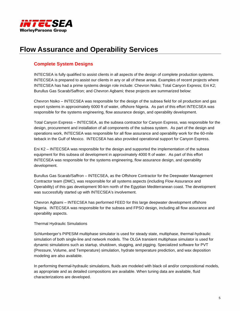
INTECSEA is fully qualified to assist clients in all aspects of the design of complete production systems. INTECSEA is prepared to assist our clients in any or all of these areas. Examples of recent projects where INTECSEA has had a prime systems design role include: Chevron Nsiko; Total Canyon Express; Eni K2; Burullus Gas Scarab/Saffron; and Chevron Agbami; these projects are summarized below:
Chevron Nsiko – INTECSEA was responsible for the design of the subsea field for oil production and gas export systems in approximately 6000 ft of water, offshore Nigeria. As part of this effort INTECSEA was responsible for the systems engineering, flow assurance design, and operability development.
Total Canyon Express – INTECSEA, as the subsea contractor for Canyon Express, was responsible for the design, procurement and installation of all components of the subsea system. As part of the design and operations work, INTECSEA was responsible for all flow assurance and operability work for the 60-mile tieback in the Gulf of Mexico. INTECSEA has also provided operational support for Canyon Express.
Eni K2 – INTECSEA was responsible for the design and supported the implementation of the subsea equipment for this subsea oil development in approximately 4000 ft of water. As part of this effort INTECSEA was responsible for the systems engineering, flow assurance design, and operability development.
Burullus Gas Scarab/Saffron – INTECSEA, as the Offshore Contractor for the Deepwater Management Contractor team (DMC), was responsible for all systems aspects (including Flow Assurance and Operability) of this gas development 90-km north of the Egyptian Mediterranean coast. The development was successfully started up with INTECSEA’s involvement.
Chevron Agbami – INTECSEA has performed FEED for this large deepwater development offshore Nigeria. INTECSEA was responsible for the subsea and FPSO design, including all flow assurance and operability aspects.
Thermal Hydraulic Simulations
Schlumberger’s PIPESIM multiphase simulator is used for steady state, multiphase, thermal-hydraulic simulation of both single-line and network models. The OLGA transient multiphase simulator is used for dynamic simulations such as startup, shutdown, slugging, and pigging. Specialized software for PVT (Pressure, Volume, and Temperature) simulation, hydrate temperature prediction, and wax deposition modeling are also available.
In performing thermal-hydraulic simulations, fluids are modeled with black oil and/or compositional models, as appropriate and as detailed compositions are available. When tuning data are available, fluid characterizations are developed.
6
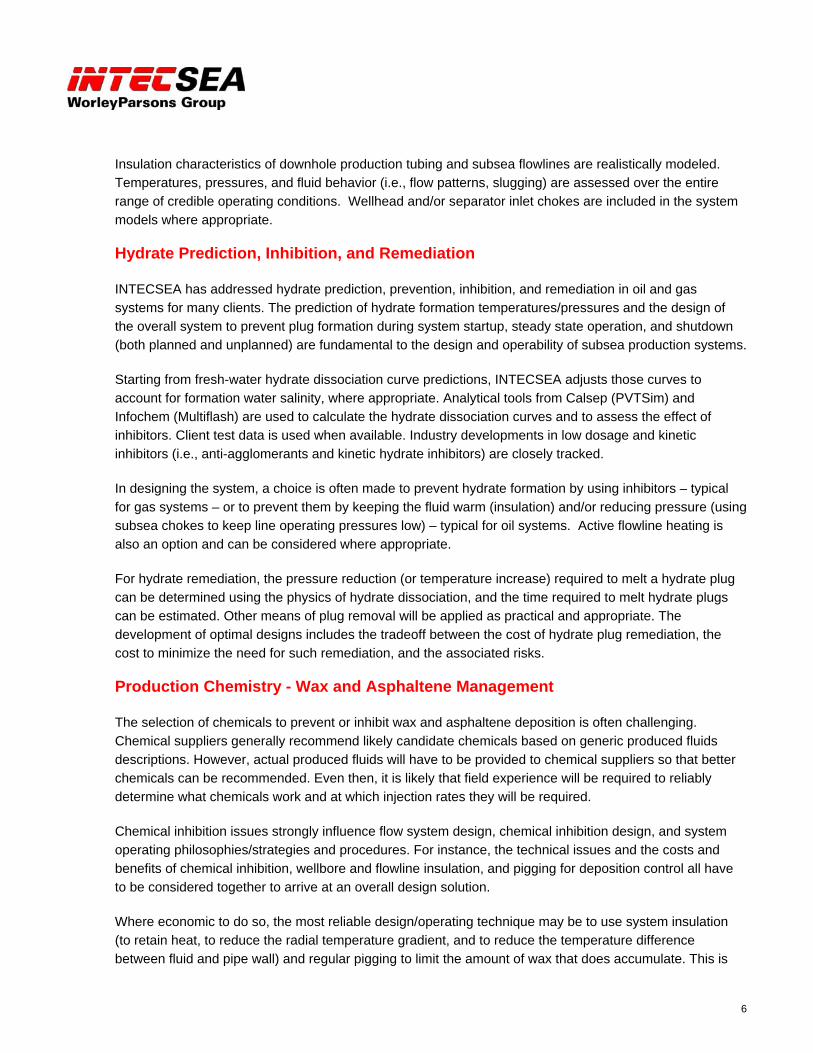
Insulation characteristics of downhole production tubing and subsea flowlines are realistically modeled. Temperatures, pressures, and fluid behavior (i.e., flow patterns, slugging) are assessed over the entire range of credible operating conditions. Wellhead and/or separator inlet chokes are included in the system models where appropriate.
Hydrate Prediction, Inhibition, and Remediation
INTECSEA has addressed hydrate prediction, prevention, inhibition, and remediation in oil and gas systems for many clients. The prediction of hydrate formation temperatures/pressures and the design of the overall system to prevent plug formation during system startup, steady state operation, and shutdown (both planned and unplanned) are fundamental to the design and operability of subsea production systems.
Starting from fresh-water hydrate dissociation curve predictions, INTECSEA adjusts those curves to account for formation water salinity, where appropriate. Analytical tools from Calsep (PVTSim) and Infochem (Multiflash) are used to calculate the hydrate dissociation curves and to assess the effect of inhibitors. Client test data is used when available. Industry developments in low dosage and kinetic inhibitors (i.e., anti-agglomerants and kinetic hydrate inhibitors) are closely tracked.
In designing the system, a choice is often made to prevent hydrate formation by using inhibitors – typical for gas systems – or to prevent them by keeping the fluid warm (insulation) and/or reducing pressure (using subsea chokes to keep line operating pressures low) – typical for oil systems. Active flowline heating is also an option and can be considered where appropriate.
For hydrate remediation, the pressure reduction (or temperature increase) required to melt a hydrate plug can be determined using the physics of hydrate dissociation, and the time required to melt hydrate plugs can be estimated. Other means of plug removal will be applied as practical and appropriate. The development of optimal designs includes the tradeoff between the cost of hydrate plug remediation, the cost to minimize the need for such remediation, and the associated risks.
Production Chemistry - Wax and Asphaltene Management
The selection of chemicals to prevent or inhibit wax and asphaltene deposition is often challenging. Chemical suppliers generally recommend likely candidate chemicals based on generic produced fluids descriptions. However, actual produced fluids will have to be provided to chemical suppliers so that better chemicals can be recommended. Even then, it is likely that field experience will be required to reliably determine what chemicals work and at which injection rates they will be required.
Chemical inhibition issues strongly influence flow system design, chemical inhibition design, and system operating philosophies/strategies and procedures. For instance, the technical issues and the costs and benefits of chemical inhibition, wellbore and flowline insulation, and pigging for deposition control all have to be considered together to arrive at an overall design solution.
Where economic to do so, the most reliable design/operating technique may be to use system insulation (to retain heat, to reduce the radial temperature gradient, and to reduce the temperature difference between fluid and pipe wall) and regular pigging to limit the amount of wax that does accumulate. This is
7
especially true if insulation is needed for other reasons (e.g., hydrate control). Nonetheless, it is often prudent to include injection capability in the system design so that chemicals can be injected if found to be necessary.
INTECSEA has worked with several clients on the flow of high wax content crudes, which have high viscosities and high pour points. Design considerations have included the determination of gelled fluid properties, gelled fluid restart, and chemical additives such pour point depressants and diluents.
In addition, INTECSEA has experience in coordinating fluid testing programs and performing quality control in laboratory measurements in the following areas: PVT properties; hydrate formation and dissociation conditions; phase envelope and hydrate kinetics in natural gas, gas condensate and black oil systems; the effect on hydrate inhibition of mixed inhibitors, salts, glycols and MeOH/EtOH; oil viscosities; wax properties (pour point, cloud point/WAT, wax amount, gel behaviour and inhibitor effects) using various testing methods; and modelling wax deposition rate and thickness.
Production Chemistry - Scale Management
Understanding of scales formation and their prevention/remediation are important for seamless operation of oil and gas production facilities. Scale formation may be due to changes in temperature, pressure, out-gassing, shifts in pH, and contact with incompatible brines. INTECSEA personnel have extensive experience in the management of scales along with their prevention and remediation. Specific capabilities include:
Reviewing and characterizing brines for their incompatibilities, and identifying scaling tendency for varying produced and injected brines in the formation, wellbore, flowlines, and topsides.
Performing analysis and modeling of produced brines and produced brine mixed with seawater and/or injection water for scale precipitation, scale dissolution, scaling index and scaling brine properties including electrical conductivity, pH, thermophysical properties, and acid gas effects.
Coordinating test programs and performing quality control for laboratory measurements of PVT properties, compositional properties, viscosities, brine properties and compatibilities, pH, acid gas effects, scales precipitations and particle sizes.
Performing line sizing and throughput analysis of chemical inhibitor injection systems.
Evaluating scale inhibitors and their compatibility with other chemicals (e.g., MeOH, glycols, corrosion inhibitors) and system materials, and providing design and chemical recommendations.
Estimating scale inhibitor dosages and delivery/injection locations needed to prevent/remediate scale precipitation.
Providing guidelines on operability issues.
Providing expertise in the state-of-the-art software needed for scale analyses including OLI ScaleChem/StreamAnalyzer and PVTSim for scale and PVT analyses, and Pipesim, Olga-2000 and Olga-Version 5 for thermal hydraulic analyses.
8
Slug Prediction and Slug Catcher Sizing
In general, for offshore floating and/or platform-based systems, slug catchers are undesirable from a weight and space perspective. Where possible, and particularly for oil/gas systems, it may be preferable to use separator inlet chokes (possibly brought into play by the level control circuitry) to control separator liquid ingress and/or dump rate, and the resultant separator volume.
The proper size of a slug catcher (or a separator sized to avoid using a slug catcher) is determined by the normal liquid and gas production rates, the dynamic variation in those rates due to operational factors (e.g., rate change - including pigging), the dynamic variation that can be accommodated by the separator, the length of slug that must be absorbed by the catcher to protect the process, the location of the slug catcher within the system (surface or subsea), and the extent to which riser gas lift, separator inlet chokes, and separator level controls can or should be integrated. In short, the use and/or design of slug catchers are part of the overall system hardware and operational design.
For normal pigging calculations, approximate techniques can be used to predict the gas and liquid behavior in front of (and behind) the pig. For more accurate prediction of pigging and other slugs, transient multiphase simulation software is used.
Production/Flow System Operability
Operability is intrinsic to the Flow Assurance/System Design Process. INTECSEA has made significant contributions in the assessment of system operability issues and in developing operating philosophies/strategies to avoid the formation of hydrate or wax at any time during system operation. These capabilities have been developed on long-offset, deepwater, subsea development projects for several clients.
“Operability” is the set of design provisions and operating strategies that ensure that the production system can be started, operated, and shut down under all conditions (planned and unplanned) throughout the operating life of the total system. In accomplishing the system design, system operability is inseparably connected to the rest of the system. Operability is, of course, especially connected to the system thermal-hydraulic design.
9
Analysis Tools
The primary flow assurance/production chemistry and analysis tools used at INTECSEA are:
PIPESIM
OLGA
Multiflash
PVTsim
OLI ScaleChem and StreamAnalyzer
In addition, ANSYS (or other FEA / CFD programs) are used for detailed flow and heat transfer modeling and analysis of insulation systems and other specialized programs are available and are used where/when needed. INTECSEA personnel have experience with other analysis tools including PIPEPHASE, HYSYS, Natasha, Fluent, Ansys, SPS and Depowax.
PIPESIM
PIPESIM is a workhorse for steady state thermal-hydraulic modeling of multiphase flow systems: both single-line and network systems. PIPESIM can model the entire system, from the reservoir to the production facilities. It competently models black oil and compositional systems. Industry-standard multiphase flow correlations and mechanistic models, including OLGA-S, are available. INTECSEA uses its own experience to assure that appropriate correlations, equations of state, fluid variables, and other system options are used for the analysis being performed. Additionally, INTECSEA is experienced with the PIPESIM Field Planning Tool, which integrates reservoir models with the hydraulic model.
OLGA
Many basic system design attributes can be determined using steady state analyses (i.e. with PIPESIM). However, transient simulation is needed to address more detailed design and operability considerations. INTECSEA uses OLGA, a transient, multi-phase, thermal-hydraulic simulation software. Common uses for OLGA include determining system/component warmup and cooldown times, blowdown fluid rates and temperatures, and slugging behavior (rate change, hydrodynamic, and more severe terrain induced slugging). In addition, the three-phase version of OLGA is necessary for predicting liquid holdup in low rate gas/condensate systems.
OLGA and transient simulation is used increasingly as more system detail is developed. The transient temperature and velocity behavior of the transported fluids figure prominently in the operability design of the system.
10
Multiflash and PVTSim
Both Multiflash and PVTSim are used for physical property and phase behavior prediction and characterization of reservoir fluids. They can both predict hydrate phase behavior and inhibition prediction. PVTSim can model the thermodynamics of waxes and asphaltenes in produced fluids. The decision of which to use within the design process is based on their individual capabilities and INTECSEA experience.
At the beginning of the process, it is particularly important to use these programs and experience to evaluate available fluid data to assess its validity (a common problem with the limited fluid data obtained from exploration wells). During the rest of the process, the programs will be used to develop fluid characterizations, to assess fluid thermodynamic behavior, and to evaluate new fluid data as it becomes available. In particular, these programs will be used to determine hydrate inhibitor performance and volume requirements. The understanding of inhibitor performance and volumes figures prominently in the operability design of the system.
Multiflash is the thermodynamic and physical property package included in PIPESIM, giving PIPESIM full compositional capability and the ability to predict hydrates. PVTSim is the thermodynamic and physical property package included in OLGA. INTECSEA also possess stand-alone licenses for both PVTSim and Multiflash.
OLI ScaleChem/StreamAnalyzer
INTECSEA personnel have experience with OLI ScaleChem and StreamAnalyzer software, which are state-of-the-art software used to solve problems related to production chemistry. They are used for: predicting scaling tendencies; solids formation; pH; ionic compositions of a given chemistry and reaction between chemicals; phase behavior; electrical conductivity; and several other properties of single and mixed brines. These properties can be predicted over the wide range of temperature and pressure conditions expected between the reservoir and topside facilities. The software has capabilities to reconcile alkalinity-pH-CO2, determine CO2 in gas and density, examine the incompatibility of methanol, ethanol, glycol, etc., and equilibrate brines with hydrocarbon phase involving compositions of the hydrocarbon fluids.

11
Production System Design Process
At INTECSEA, production system design, and particularly Flow Assurance and Operability, embodies a whole-system approach. Design and operation of the system are inexorably linked and must be treated as such throughout the design process.
Figure 3 below is representative of the overall Flow Assurance and Operability Design Process that is used to develop the design of the production system. The process is shown in a sequential fashion for illustration purposes. In practice, multiple paths are followed simultaneously and the process is highly iterative and interactive; involving input and interchange with the entire system design team.
Figure 3: Flow Assurance and Operability – Design Process Map
ESTABLISH DESIGN BASIS
HYDRAULIC DESIGN THERMAL DESIGN
Thermal-Hydraulics andFluid Behavior
OK?
ASSESS FLUIDPHASE
BEHAVIOR
Processing Capabilities Processing Pres./Temps. Metering Storage Volumes Export Requirements PCS Chemical Injection Pumps Chemical Storage Flare Requirements Utility & Emergency Power Surge/Slug Volumes Surge/Slug Control
Procedures Valve Sequences Pump Sequences Chemical Injection Rates Activity Durations
Systemand Economics
Optimum?
ASSESS SYSTEMECONOMICS
DONE
Reservoir Behavioras f(t) Productivity Index Production Profiles Pres. vs. Depletion Temperature
Fluid Behavior PVT Characterization Hydrates Wax Asphaltenes
Flowline Routing Bathymetry Seawater Temp.
ModelFlowlines
Thermal-Hydraulics OK?
Select Tubingand Flowline
Diameters and# of Flowlines
Select Tubingand
FlowlineInsulation
Host Facilities Separator Pres. Acceptable Arrival Temp.
ASSESSTRANSIENTTHERMAL-
HYDRAULICS
FLOW SYSTEM THERMAL-HYDRAULIC DESIGN AND FLUIDBEHAVIOR
HydratesWax
AsphaltenesScale
PredictionControl
RemediationHOST FACILITY
REQUIREMENTS
CAPITAL COSTOPERATING COSTS
NET PRESENT VALUE
Reservoir, FlowSystem, and Host Design
Compatible?
OPERATINGSTRATEGIES
Plateau andEOL Conditions
Satisfied?
ModelWells
ModelFlowlines
ModelWells
No
Yes
Yes
No
No
Yes
Yes
Flowlines, Pipelines, & Risers Subsea Equipment Umbilicals Wellbores
INTERFACE WITHMECHANICAL DESIGN
Startup / WarmupShutdown / CooldownTurndown / Ramp-up
DepressurizationSlugging
No
No
Yes
ASSESS OTHERINTERFACES
ReservoirProduction Operations
12
Steps of an effective process include:
Develop a starting point for the work including such things as feasible mechanical design options for the system, operability provisions that are likely to be appropriate, chemical injection options, capabilities of (and/or requirements for) the host facility, and the effect of these early decisions on system economics. For this first step, only very cursory information may be available from other members of the ultimate design team.
Interact with team members representing other parts of the system to determine modeling/analysis bases, options, and desired outcomes.
Perform analytic/design work to the appropriate level of detail (too much detail is no better than just the right amount of detail).
Test results against the needs and characteristics of the rest of the system.
Reevaluate design requirements (including design bases) and direction as required to attain goals.
Continue the process until final system and economic optimization is achieved.
A prescribed path through the process cannot be tightly defined. Large measures of skill, experience, and judgment are involved.
The flow assurance design process involves multiple technical interfaces. Reservoir engineering, completions engineering, pipeline/flowline mechanical design, subsea and controls engineering, facilities engineering, and operational and HSE personnel will all interact with flow assurance during the design process. The numerous interfaces necessitate effective project management. Interactions between INTECSEA’s strong Subsea, Pipelines, and Flow Assurance disciplines and between INTECSEA’s Flow Assurance Engineers and client reservoir, operations, and project personnel greatly aid the design process.
The flow assurance and operability design and analysis process should start at the earliest conception of the system and often continues through the operation of the system is decommissioned. Early Flow Assurance and Operability involvement is particularly important for the fast-track projects being considered in the industry today.
Flow Assurance and Operability Design Stages
The degree of Flow Assurance and Operability detail required depends upon the stage of engineering that the design process is in.
In early stages of the design process, relatively little of the system input will be finalized. The amount of detail in the models and the conclusions drawn from them will be relatively cursory. The cross effects of reservoir pressure and temperature, tubing diameter and insulation, flowline diameter and insulation, the number of flowlines, flowline routing, holdup, and platform arrival temperatures and pressures will be

13
evaluated. A large number of models may be run in a short period of time to bracket the solution boundaries.
A major effort early in the design process will be to establish the design basis. All aspects of the system, such as fluid characteristics, reservoir behavior, site characteristics, and host facilities should be reflected in the design basis. The design basis should include sufficient conservatism to offset poor or missing data. INTECSEA has the experience to help avoid unnecessary conservatism.
As the design progresses, the attention paid to detail will increase. The “trick” is to use INTECSEA knowledge and experience to analyze, as thoroughly as needed, and to develop the design but to not unnecessarily spend resources on detailed analyses that will have to be redone at a later stage after definitive data is available.
As the design of the system moves into the detailed design and fabrication stages, the flow assurance effort is likely to shift toward more detailed analyses to support operating procedure development and hardware and facilities designs and evaluations. At the same time, systems engineers will assure that system design changes that might affect flow assurance and operability provisions are thoroughly evaluated in the flow assurance context.
System economics and risk management are over-riding considerations in the design process and are continuously evaluated.
14
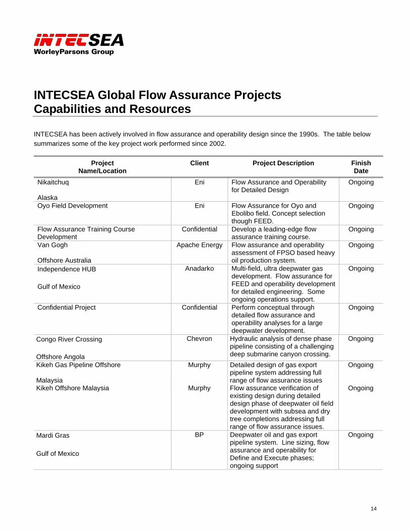
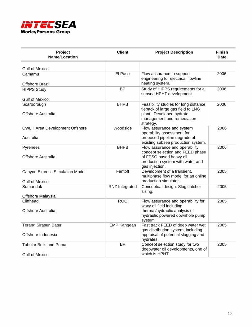
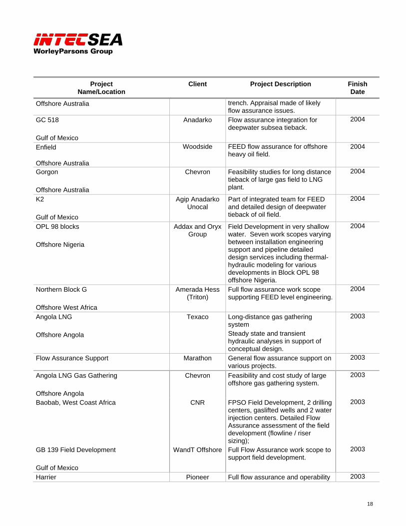
INTECSEA Global Flow Assurance Projects Capabilities and Resources
INTECSEA has been actively involved in flow assurance and operability design since the 1990s. The table below summarizes some of the key project work performed since 2002.
Project Name/Location
Client Project Description Finish Date
Nikaitchuq Alaska
Eni Flow Assurance and Operability for Detailed Design
Ongoing
Oyo Field Development Eni Flow Assurance for Oyo and Ebolibo field. Concept selection though FEED.
Ongoing
Flow Assurance Training Course Development
Confidential Develop a leading-edge flow assurance training course.
Ongoing
Van Gogh Offshore Australia
Apache Energy Flow assurance and operability assessment of FPSO based heavy oil production system.
Ongoing
Independence HUB Gulf of Mexico
Anadarko Multi-field, ultra deepwater gas development. Flow assurance for FEED and operability development for detailed engineering. Some ongoing operations support.
Ongoing
Confidential Project Confidential Perform conceptual through detailed flow assurance and operability analyses for a large deepwater development.
Ongoing
Congo River Crossing Offshore Angola
Chevron Hydraulic analysis of dense phase pipeline consisting of a challenging deep submarine canyon crossing.
Ongoing
Kikeh Gas Pipeline Offshore Malaysia
Murphy Detailed design of gas export pipeline system addressing full range of flow assurance issues
Ongoing
Kikeh Offshore Malaysia Murphy Flow assurance verification of existing design during detailed design phase of deepwater oil field development with subsea and dry tree completions addressing full range of flow assurance issues.
Ongoing
Mardi Gras Gulf of Mexico
BP Deepwater oil and gas export pipeline system. Line sizing, flow assurance and operability for Define and Execute phases; ongoing support
Ongoing

15
Project Name/Location
Client Project Description Finish Date
Nsiko Offshore Nigeria
Chevron Flow Assurance and Operability Strategy for Pre-FEED Subsea Facilities/Export Pipeline
2007
Gotcha Gulf of Mexico
Total Flow Assurance and Operability for pre-FEED
2007
Deep Panuke Offshore Nova Scotia
EnCana Flow assurance and production chemistry for pre-FEED
2007
Tubular Bells BP Flow Assurance and Operability for pre-FEED study
2007
GC 298 and EB 157 Gulf of Mexico
Eni Flow assurance and operability studies for detailed engineering.
2007
Oooguruk Offshore Alaskan North Slope
Pioneer Offshore oil development using subsea and onshore multiphase production lines in Arctic environment. Flow assurance and operability for pre-FEED and FEED.
2007
Canyon Express Operational Support Gulf of Mexico
Total Flow assurance and operability support to Canyon Express operations.
2007
Sapphire Field West Delta Deep Offshore Egypt in the Eastern Mediterranean
Burullus Gas INTECSEA performed the concept selection and FEED for Sapphire. Areas of work included field architecture, flow assurance, pipelines, controls and subsea hardware. INTECSEA also performed the detailed flow assurance work for the project.
2007
Simian Field West Delta Deep Offshore Egypt in Eastern Mediterranean.
Burullus Gas Bechtel-INTECSEA Consortium commenced Concept Definition Studies in 2001 and completed FEED in June 2002. INTECSEA have continued supporting the integrated Management team for the EPIC phase
2007
Ceiba Offshore Equatorial Guinea
Hess Hydraulic analysis of gas lift requirements and sizing the gas lift distribution system.
2007
TIOF West Africa
Woodside Flow Assurance and Operability for pre-FEED
2006
Blind Faith Gulf of Mexico
Chevron Deepwater, subsea development of HPHT oil field. Conceptual and pre-FEED flow assurance studies.
2006
Neptune Enbridge Hydraulic analysis supporting FEED for export pipelines.
2006
16
Project Name/Location
Client Project Description Finish Date
Gulf of Mexico Camamu Offshore Brazil
El Paso Flow assurance to support engineering for electrical flowline heating system.
2006
HIPPS Study Gulf of Mexico
BP Study of HIPPS requirements for a subsea HPHT development.
2006
Scarborough Offshore Australia
BHPB Feasibility studies for long distance tieback of large gas field to LNG plant. Developed hydrate management and remediation strategy.
2006
CWLH Area Development Offshore Australia
Woodside Flow assurance and system operability assessment for proposed pipeline upgrade of existing subsea production system.
2006
Pyrenees Offshore Australia
BHPB Flow assurance and operability concept selection and FEED phase of FPSO based heavy oil production system with water and gas injection.
2006
Canyon Express Simulation Model Gulf of Mexico
Fantoft Development of a transient, multiphase flow model for an online production simulator.
2005
Sumandak Offshore Malaysia
RNZ Integrated Conceptual design. Slug catcher sizing.
2005
Cliffhead Offshore Australia
ROC Flow assurance and operability for waxy oil field including thermal/hydraulic analysis of hydraulic powered downhole pump system
2005
Terang Sirasun Batur Offshore Indonesia
EMP Kangean Fast track FEED of deep water wet gas distribution system, including appraisal of potential slugging and hydrates.
2005
Tubular Bells and Puma Gulf of Mexico
BP Concept selection study for two deepwater oil developments, one of which is HPHT.
2005

17
Project Name/Location
Client Project Description Finish Date
Neptune LNG Terminal Atlantic Coast
Suez Energy Flow assurance and hydraulic studies to support design engineering for offshore LNG offloading terminal.
2005
Frade 1Offshore Brazil
Chevron Deepwater, subsea heavy oil development tied back to a FPSO. Full flow assurance and operability workscope for FEED.
2005
Olowi Offshore Gabon
Pioneer Feasibility and FEED studies for high pour point oil development.
2005
Ozona Deep Gulf of Mexico
Marathon Pioneer
Conceptual/feasibility study of marginal deepwater oil field.
2005
Triton Gulf of Mexico
Dominion Flow assurance and operability for deepwater subsea tieback. Total system design including line sizing, insulation requirements, chemical injection, and wax deposition modeling.
2005
Falcon Corridor Gulf of Mexico
Pioneer Full flow assurance and operability for adding wells to the Falcon production system, a long distance tieback of a gas field.
2004
Agbami Offshore Nigeria
Chevron Deepwater, subsea oil development. Full Flow Assurance work scope for conceptual studies and FEED. Steady state and transient thermal-hydraulic simulations to determine line sizes, insulation requirements, hydrate and wax control, slugging assessment, and subsea operating philosophy.
2004
Baobab Field Flow Assurance Studies Equatorial Guinea
Canadian Natural
Resources
The Baobab field is located offshore Equatorial Guinea is in very deep water with the FPSO located in 900 meters and the wells in depths of up to 1400 meters. The low reservoir pressure and the heavy oil emulsion led to flow assurance challenges, particularly in terms of slugging and start up.
2004
Neptune Gulf of Mexico
BHP-Billiton Flow assurance studies for pre-FEED design of deepwater tieback of oil field.
2004
Timor Leste ‘Sunrise’
Woodside Sizing of 150 km gas condensate pipeline crossing 3300 m Timor
2004
18
Project Name/Location
Client Project Description Finish Date
Offshore Australia trench. Appraisal made of likely flow assurance issues.
GC 518 Gulf of Mexico
Anadarko Flow assurance integration for deepwater subsea tieback.
2004
Enfield Offshore Australia
Woodside FEED flow assurance for offshore heavy oil field.
2004
Gorgon Offshore Australia
Chevron Feasibility studies for long distance tieback of large gas field to LNG plant.
2004
K2 Gulf of Mexico
Agip Anadarko Unocal
Part of integrated team for FEED and detailed design of deepwater tieback of oil field.
2004
OPL 98 blocks Offshore Nigeria
Addax and Oryx Group
Field Development in very shallow water. Seven work scopes varying between installation engineering support and pipeline detailed design services including thermal-hydraulic modeling for various developments in Block OPL 98 offshore Nigeria.
2004
Northern Block G Offshore West Africa
Amerada Hess (Triton)
Full flow assurance work scope supporting FEED level engineering.
2004
Angola LNG Offshore Angola
Texaco Long-distance gas gathering system Steady state and transient hydraulic analyses in support of conceptual design.
2003
Flow Assurance Support Marathon General flow assurance support on various projects.
2003
Angola LNG Gas Gathering Offshore Angola
Chevron Feasibility and cost study of large offshore gas gathering system.
2003
Baobab, West Coast Africa CNR FPSO Field Development, 2 drilling centers, gaslifted wells and 2 water injection centers. Detailed Flow Assurance assessment of the field development (flowline / riser sizing);
2003
GB 139 Field Development Gulf of Mexico
WandT Offshore Full Flow Assurance work scope to support field development.
2003
Harrier Pioneer Full flow assurance and operability 2003
19
Project Name/Location
Client Project Description Finish Date
Gulf of Mexico
work scope to develop fast-track, long distance tieback of a gas field.
Ibhubesi Offshore South Africa
Forest Oil Conceptual/feasibility study of remote gas development. Full flow assurance work scope to support field development planning.
2003
Neptune Gulf of Mexico
BHPB and Marathon
Concept evaluation and feasibility study of deepwater oil development.
2003
North Idku Field Mediterranean Sea
GEOGE Pre-feasibility study addendum of North Idku Field including field architecture development comprising, pipeline Flow Assurance and hardware requirements, subsea controls and development of CAPEX/OPEX cost estimates
2003
Okwori Offshore Nigeria
Addax and Oryx Group
Field development using an FPSO, moored in 140 meters of water, linked to 9 subsea wells. Field architecture - subsea layout and study on FPSO position optimization; Pipeline hydraulics study; FEED; Evaluation of subsea equipment for refurbishment and utilization
2003
Sakhalin Island ExxonMobil Onshore and offshore developed in near-Arctic environment. Flow assurance work scope for FEED: line sizing, hydrate control, wax management, transient analysis, and system operability.
2003
Sarawak M4 Shell Sabah Transient thermal-hydraulic study of shallow water gas-condensate tieback.
2003
Scarab/Saffron Mediterranean - Offshore Egypt
Burullus Gas (BG, Edison,
EGPC)
Deepwater 90-km subsea gas tie-back. Full systems/Flow Assurance and Operability work scope for FEED and detailed engineering. Steady state and transient thermal-hydraulic simulations to determine line sizes, hydrate control, slugging assessment, metering, and subsea operating philosophy.
2003
20
Project Name/Location
Client Project Description Finish Date
Canyon Express Gulf of Mexico
Total Deepwater 56-mile subsea gas tie-back Full Flow Assurance work scope for FEED. Production system hydraulics, steady state and transient. Subsea multiphase flow metering considerations. Chemical injection system design. Operating philosophy.
2002
Hydrate Control Best Practices Norsk Hydro Hydrate control and remediation study to develop “best practices” for deepwater oil developments.
2002
Yuralpa Pipeline Ecuador Burlington Resources
Steady state and transient analysis of heavy oil pipeline.
2002
21
Selected Project Resumes
DeepStar Flow Assurance Design Guide
Mariner Pluto Subsea Project
Agbami Field Development
Texaco Angola LNG Project
Canyon Express Project
Olowi Project - Flow Assurance FEED
Independence HUB (MC920) Subsea Field
K2 Field Development Production Fac
ChevronTexaco Blind Faith Field
CNR - Baobab Field Flow Assurance
Scarab Saffron Subsea Development
CNOOC China Limited, CNOOC-Panya Pre- Commissioning Study
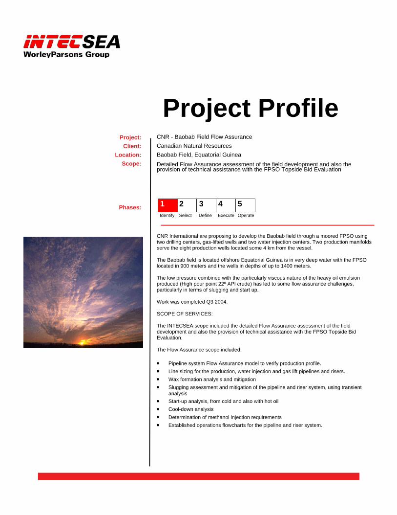
CNR International are proposing to develop the Baobab field through a moored FPSO using two drilling centers, gas-lifted wells and two water injection centers. Two production manifolds serve the eight production wells located some 4 km from the vessel. The Baobab field is located offshore Equatorial Guinea is in very deep water with the FPSO located in 900 meters and the wells in depths of up to 1400 meters. The low pressure combined with the particularly viscous nature of the heavy oil emulsion produced (High pour point 22º API crude) has led to some flow assurance challenges, particularly in terms of slugging and start up. Work was completed Q3 2004. SCOPE OF SERVICES: The INTECSEA scope included the detailed Flow Assurance assessment of the field development and also the provision of technical assistance with the FPSO Topside Bid Evaluation. The Flow Assurance scope included: • Pipeline system Flow Assurance model to verify production profile. • Line sizing for the production, water injection and gas lift pipelines and risers. • Wax formation analysis and mitigation • Slugging assessment and mitigation of the pipeline and riser system, using transient
analysis • Start-up analysis, from cold and also with hot oil • Cool-down analysis • Determination of methanol injection requirements • Established operations flowcharts for the pipeline and riser system.
Project Profile CNR - Baobab Field Flow Assurance Canadian Natural Resources Baobab Field, Equatorial Guinea Detailed Flow Assurance assessment of the field development and also the provision of technical assistance with the FPSO Topside Bid Evaluation
Project: Client:
Location: Scope:
Phases: 1 2 3 4 5 Identify Select Define Execute Operate
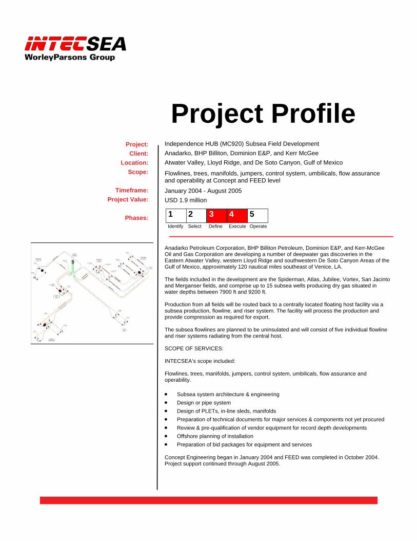
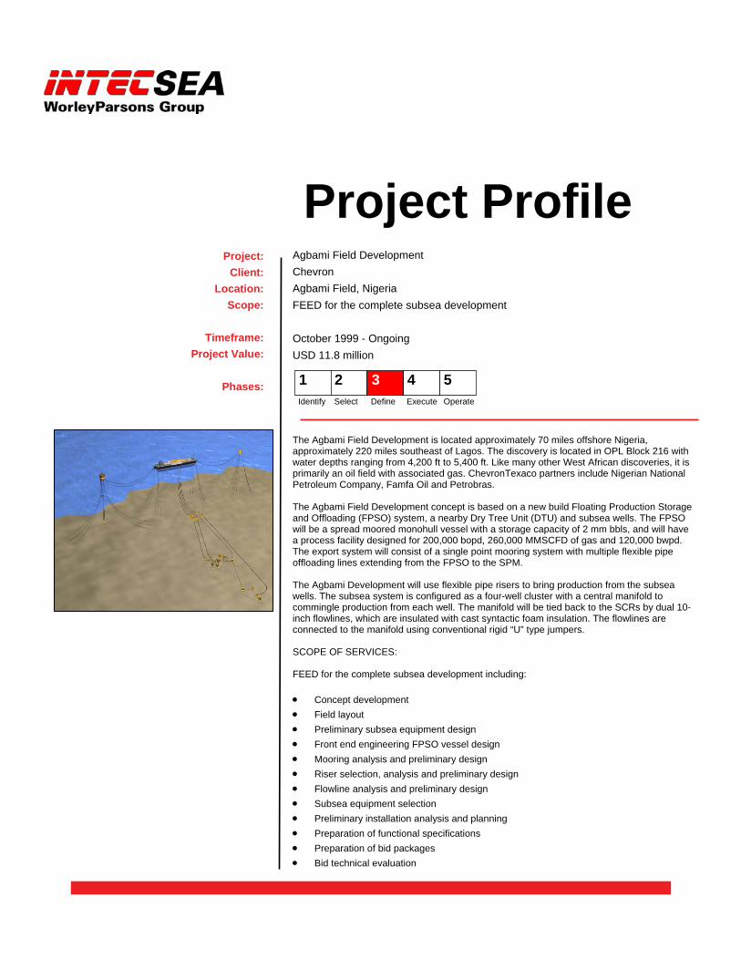
Anadarko Petroleum Corporation, BHP Billiton Petroleum, Dominion E&P, and Kerr-McGee Oil and Gas Corporation are developing a number of deepwater gas discoveries in the Eastern Atwater Valley, western Lloyd Ridge and southwestern De Soto Canyon Areas of the Gulf of Mexico, approximately 120 nautical miles southeast of Venice, LA. The fields included in the development are the Spiderman, Atlas, Jubilee, Vortex, San Jacinto and Merganser fields, and comprise up to 15 subsea wells producing dry gas situated in water depths between 7900 ft and 9200 ft. Production from all fields will be routed back to a centrally located floating host facility via a subsea production, flowline, and riser system. The facility will process the production and provide compression as required for export. The subsea flowlines are planned to be uninsulated and will consist of five individual flowline and riser systems radiating from the central host. SCOPE OF SERVICES: INTECSEA’s scope included: Flowlines, trees, manifolds, jumpers, control system, umbilicals, flow assurance and operability. • Subsea system architecture & engineering • Design or pipe system • Design of PLETs, in-line sleds, manifolds • Preparation of technical documents for major services & components not yet procured • Review & pre-qualification of vendor equipment for record depth developments • Offshore planning of installation • Preparation of bid packages for equipment and services Concept Engineering began in January 2004 and FEED was completed in October 2004. Project support continued through August 2005.
Project Profile Independence HUB (MC920) Subsea Field Development Anadarko, BHP Billiton, Dominion E&P, and Kerr McGee Atwater Valley, Lloyd Ridge, and De Soto Canyon, Gulf of Mexico
Flowlines, trees, manifolds, jumpers, control system, umbilicals, flow assurance and operability at Concept and FEED level
January 2004 - August 2005 USD 1.9 million
Project: Client:
Location: Scope:
Timeframe:
Project Value:
Phases: 1
2 3 4 5 Identify Select Define Execute Operate
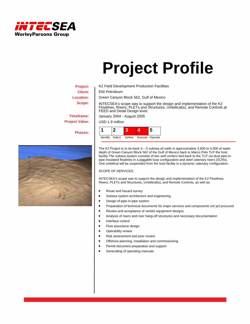
The K2 Project is to tie-back 3 – 5 subsea oil wells in approximately 3,900 to 4,500 of water depth of Green Canyon Block 562 of the Gulf of Mexico back to Marco Polo TLP the host facility The subsea system consists of two well centers tied back to the TLP via dual pipe-in- pipe insulated flowlines in a piggable loop configuration and steel catenary risers (SCRs). One umbilical will be suspended from the host facility in a dynamic catenary configuration. SCOPE OF SERVICES: INTECSEA’s scope was to support the design and implementation of the K2 Flowlines, Risers, PLETs and Structures, Umbilical(s), and Remote Controls, as well as: • Route and hazard survey • Subsea system architecture and engineering • Design of pipe-in-pipe system • Preparation of technical documents for major services and components not yet procured • Review and acceptance of vendor equipment designs • Analysis of risers and riser hang-off structures and necessary documentation • Interface control • Flow assurance design • Operability review • Risk assessment and peer review • Offshore planning, installation and commissioning • Permit document preparation and support • Generating of operating manuals
Project Profile K2 Field Development Production Facilities ENI Petroleum Green Canyon Block 562, Gulf of Mexico
INTECSEA’s scope was to support the design and implementation of the K2 Flowlines, Risers, PLETs and Structures, Umbilical(s), and Remote Controls at FEED and Detail Design level. January 2004 - August 2005 USD 1.9 million
Project: Client:
Location: Scope:
Timeframe: Project Value:
Phases: 1
2 3 4 5
Identify Select Define Execute Operate

Pioneer is developing the Olowi Field, offshore Gabon, with four fixed platforms, A, B and C/D. The oil has a high pour point and this poses many flow assurance challenges. The produced oil and gas from wellhead platforms A and B are sent via flowlines to platform C and commingled with production at C and processed. The gas is pressurized and transported back by flowlines and re-injected into the reservoir. Water injection flowlines run from platform C to A and B. Processed oil is exported via two insulated pipelines and flexible risers to a FSO. SCOPE OF SERVICES: INTECSEA began by reviewing previous design work to verify that the proposed design met requirements for producing high wax content oil. INTECSEA continued into FEED developing the detailed design for the Olowi production and transportation systems INTECSEA’s scope included: • Preparing flow assurance input for the design basis • Assessing previous design reports • Supporting laboratory fluid studies • Flowline sizing • Flowline insulation requirements • Process heating requirements • Wellbore heating • Operability analysis • Development of operating philosophies • Interfacing with topsides and pipeline design The selected design relied on maintaining high temperatures to prevent wax problems. A significant effort was involved in determining insulation and heating requirements. Detailed wellbore models were developed to simulate a unique wellbore heating system.
Project Profile Olowi Project - Flow Assurance FEED Pioneer Resources Gabon-Olowi, Ltd. Olowi Field, Gabon
INTECSEA began by reviewing previous design work to verify that the proposed design met requirements for producing high wax content oil. INTECSEA continued into FEED. September 2003 - November 2004 USD 528 thousand
Project: Client:
Location: Scope:
Timeframe: Project Value:
Phases: 1 2 3 4 5
Identify Select Define Execute Operate
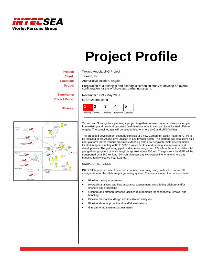
Texaco and Sonangol are planning a project to gather non-associated and associated gas from existing and new and proposed field developments in various blocks located offshore Angola. The combined gas will be used to feed onshore LNG and LPG facilities. The proposed development scenario consists of a new Gathering Facility Platform (GFP) to be installed at the Atum/Polvo location in 126 ft water depth. The platform will also serve as a riser platform for the various pipelines extending from new deepwater field developments located in approximately 4000 to 5000 ft water depths, and existing shallow water field developments. The gathering pipeline diameters range from 12-inch to 24-inch, and the total gas gathering system pipeline length is approximately 500 km. The gas from the GFP will be transported by a 260 km long, 30-inch diameter gas export pipeline to an onshore gas handling facility located near Luanda. SCOPE OF SERVICES: INTECSEA prepared a technical end economic screening study to develop an overall configuration for the offshore gas gathering system. The study scope of services included: • Pipeline routing assessment • Hydraulic analyses and flow assurance assessment, considering offshore and/or
onshore gas processing • Onshore and offshore process facilities requirements for condensate removal and
handling • Pipeline mechanical design and installation analyses • Pipeline shore approach and landfall evaluations • Gas gathering system cost estimates
Project Profile Texaco Angola LNG Project Texaco, Inc. Atum/Polvo location, Angola Preparation of a technical end economic screening study to develop an overall configuration for the offshore gas gathering system.
November 1999 - May 2001 USD 225 thousand
Project: Client:
Location: Scope:
Timeframe:
Project Value:
Phases:
TO LUANDALNG PLANT
QUILUMA
FSO
LOMBO EAST
TUBARAO
SULELESOUTH A
GATHERINGFACILITY
ATUM / POLVO
SULELEWEST
SULELESOUTH B
FPS
FPS
GIRASSOL
FPS
DALIA
FPS
FPS
FPS
FPS
LOMBO NORTH
ROSA LIRIO
3RD PRODUCTIONCENTER
DIKANZA / KISSANJE
HUNGO/CHOCALHO
AVERAGE WD 126'
BLOCK 15(ESSO)
BLOCK 18(BP/AMOCO)
DSV INSTALLSUBEA
TIE-IN #2
BLOCK 17(ELF)
AVERAGE WD 4500'
AVERAGE WD 4300'
AVERAGE WD 4300'
J-LAYINSTALLPLEM 3
J-LAYINSTALLPLEM 2
J-LAYINSTALLPLEM 1
DSVINSTALLSSIS
ENGUIANORTH
TO LUANDALNG PLANT
EXISTING OILPIPELINE
QUILUMA
BLOCK 1(TEXACO)
A3
A5
BLOCK 2(TEXACO)
1 2 3 4 5 Identify Select Define Execute Operate
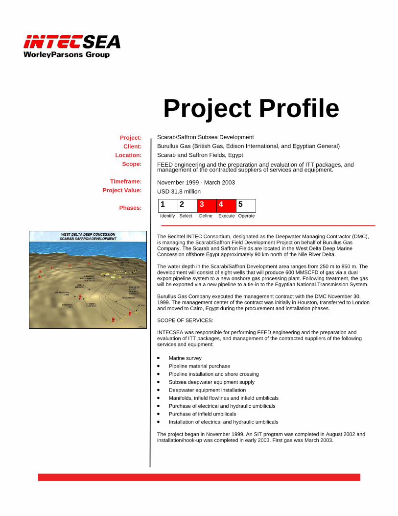
The Bechtel INTEC Consortium, designated as the Deepwater Managing Contractor (DMC), is managing the Scarab/Saffron Field Development Project on behalf of Burullus Gas Company. The Scarab and Saffron Fields are located in the West Delta Deep Marine Concession offshore Egypt approximately 90 km north of the Nile River Delta. The water depth in the Scarab/Saffron Development area ranges from 250 m to 850 m. The development will consist of eight wells that will produce 600 MMSCFD of gas via a dual export pipeline system to a new onshore gas processing plant. Following treatment, the gas will be exported via a new pipeline to a tie-in to the Egyptian National Transmission System. Burullus Gas Company executed the management contract with the DMC November 30, 1999. The management center of the contract was initially in Houston, transferred to London and moved to Cairo, Egypt during the procurement and installation phases. SCOPE OF SERVICES: INTECSEA was responsible for performing FEED engineering and the preparation and evaluation of ITT packages, and management of the contracted suppliers of the following services and equipment: • Marine survey • Pipeline material purchase • Pipeline installation and shore crossing • Subsea deepwater equipment supply • Deepwater equipment installation • Manifolds, infield flowlines and infield umbilicals • Purchase of electrical and hydraulic umbilicals • Purchase of infield umbilicals • Installation of electrical and hydraulic umbilicals The project began in November 1999. An SIT program was completed in August 2002 and installation/hook-up was completed in early 2003. First gas was March 2003.
Project Profile Scarab/Saffron Subsea Development Burullus Gas (British Gas, Edison International, and Egyptian General) Scarab and Saffron Fields, Egypt FEED engineering and the preparation and evaluation of ITT packages, and management of the contracted suppliers of services and equipment.
November 1999 - March 2003 USD 31.8 million
Project: Client:
Location: Scope:
Timeframe:
Project Value:
Phases: 1
2 3 4 5 Identify Select Define Execute Operate

The Mariner Pluto Field Development is located approximately 60 miles offshore Louisiana in Mississippi Canyon Block 674 located in a water depth of 2,700 ft. The field is operated by a joint venture between Burlington Resources and Mariner Energy, Inc. At the present time, the 29-mile 8-inch steel flowline tied back to a Marathon platform in South Pass 89 is the second longest subsea tie-back in the Gulf of Mexico. The field will produce gas and condensate with a initial flow rate of 70 MMCFD through a rigid jumper to a Pipeline End Termination PLET and then to the platform. The flowline and PLET installation were performed by a reel barge. The field has a chemical injection umbilical and a control umbilical installed by a DP DSV parallel to the flowline. SCOPE OF SERVICES: INTECSEA was responsible for the following services: • Project management • Flow assurance analyses • Flowline surveys supervision and route selection • Flowline and umbilical design • Flowline and umbilical construction supervision • Riser & I-Tube design • Platform leg clamp design • Umbilical manufacturing quality assurance Production from the Pluto Field started in October 1999.
Project Profile Mariner Pluto Subsea Project Mariner Energy, Inc. Mississippi Canyon Block 674, Gulf of Mexico
Project Management, Flow Assurance Analyses, Flowline Survey Supervision and Route Selection, etc.
April 1998 - October 1999 USD 493 thousand
Project: Client:
Location: Scope:
Timeframe:
Project Value:
Phases: 1 2 3 4 5 Identify Select Define Execute Operate
As part of the Texaco-led DeepStar Program, INTECSEA developed a comprehensive Flow Assurance Design Guide. The Flow Assurance Design Guide was to set forth basic engineering requirements and recommended practice deemed necessary for the reliable and cost effective design and operation of multiphase production systems. Because flow assurance is a multi-discipline activity, the Flow Assurance Design Guide addressed each discipline and explains how each fit in the overall design process. Major flow assurance technologies covered in the guide are: • PVT and fluid properties • Steady state and transient multiphase flow • Interface with reservoir and process facilities • Hydrate, paraffin, asphaltene, and other solids • Corrosion, erosion and sand control Various examples of good design practice are provide throughout the guide. Design engineers with a knowledge of flow assurance were the intended audience for the Flow Assurance Design Guide. SCOPE OF SERVICES: INTECSEA was responsible for compiling the Flow Assurance Design Guide with information provided by DeepStar member companies and from the open literature. Additionally, INTECSEA developed some sections of the guide using its own experience and expertise. In compiling the Flow Assurance Design Guide, INTECSEA was required to critically review numerous documents, guidelines, and articles and then assimilate the information in a logical and useful manner. Additionally, INTECSEA provided administrative services for the development of the guide. The project began in October of 1998 and was completed in May of 2000.
Project Profile DeepStar Flow Assurance Design Guide Texaco, Inc. N/A Compilation of the Flow Assurance Design Guide using information from DeepStar and development of some sections of the guide using its own experience and expertise. October 1998 - May 2000
Project: Client:
Location: Scope:
Timeframe:
Phases: 1 2 3 4 5 Identify Select Define Execute Operate
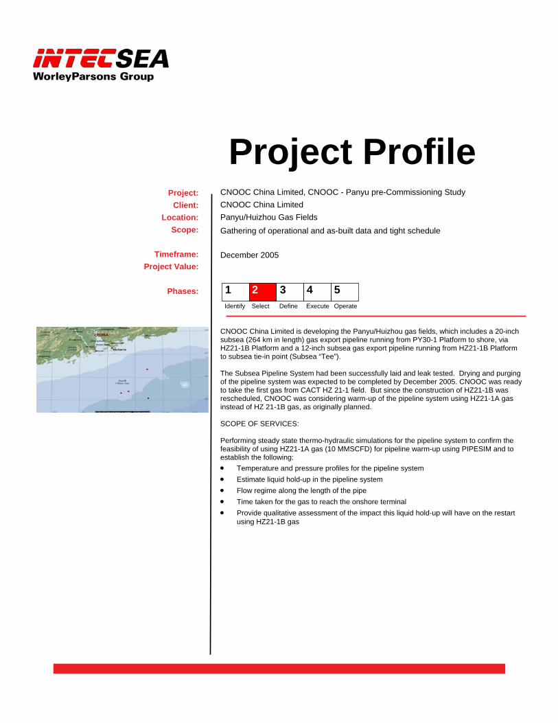
CNOOC China Limited is developing the Panyu/Huizhou gas fields, which includes a 20-inch subsea (264 km in length) gas export pipeline running from PY30-1 Platform to shore, via HZ21-1B Platform and a 12-inch subsea gas export pipeline running from HZ21-1B Platform to subsea tie-in point (Subsea “Tee”). The Subsea Pipeline System had been successfully laid and leak tested. Drying and purging of the pipeline system was expected to be completed by December 2005. CNOOC was ready to take the first gas from CACT HZ 21-1 field. But since the construction of HZ21-1B was rescheduled, CNOOC was considering warm-up of the pipeline system using HZ21-1A gas instead of HZ 21-1B gas, as originally planned. SCOPE OF SERVICES: Performing steady state thermo-hydraulic simulations for the pipeline system to confirm the feasibility of using HZ21-1A gas (10 MMSCFD) for pipeline warm-up using PIPESIM and to establish the following: • Temperature and pressure profiles for the pipeline system • Estimate liquid hold-up in the pipeline system • Flow regime along the length of the pipe • Time taken for the gas to reach the onshore terminal • Provide qualitative assessment of the impact this liquid hold-up will have on the restart
using HZ21-1B gas
Project Profile CNOOC China Limited, CNOOC - Panyu pre-Commissioning Study CNOOC China Limited Panyu/Huizhou Gas Fields Gathering of operational and as-built data and tight schedule
December 2005
Project: Client:
Location: Scope:
Timeframe:
Project Value:
Phases: 1 2 3 4 5 Identify Select Define Execute Operate
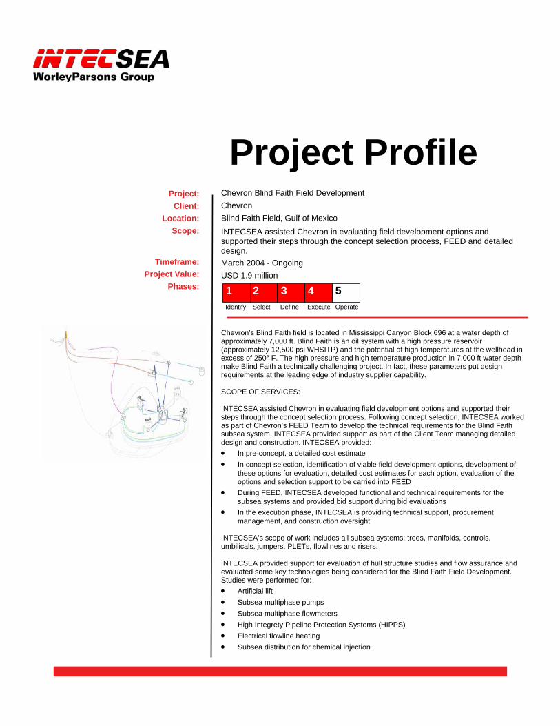
Chevron’s Blind Faith field is located in Mississippi Canyon Block 696 at a water depth of approximately 7,000 ft. Blind Faith is an oil system with a high pressure reservoir (approximately 12,500 psi WHSITP) and the potential of high temperatures at the wellhead in excess of 250° F. The high pressure and high temperature production in 7,000 ft water depth make Blind Faith a technically challenging project. In fact, these parameters put design requirements at the leading edge of industry supplier capability. SCOPE OF SERVICES: INTECSEA assisted Chevron in evaluating field development options and supported their steps through the concept selection process. Following concept selection, INTECSEA worked as part of Chevron’s FEED Team to develop the technical requirements for the Blind Faith subsea system. INTECSEA provided support as part of the Client Team managing detailed design and construction. INTECSEA provided: • In pre-concept, a detailed cost estimate • In concept selection, identification of viable field development options, development of
these options for evaluation, detailed cost estimates for each option, evaluation of the options and selection support to be carried into FEED
• During FEED, INTECSEA developed functional and technical requirements for the subsea systems and provided bid support during bid evaluations
• In the execution phase, INTECSEA is providing technical support, procurement management, and construction oversight
INTECSEA’s scope of work includes all subsea systems: trees, manifolds, controls, umbilicals, jumpers, PLETs, flowlines and risers. INTECSEA provided support for evaluation of hull structure studies and flow assurance and evaluated some key technologies being considered for the Blind Faith Field Development. Studies were performed for: • Artificial lift • Subsea multiphase pumps • Subsea multiphase flowmeters • High Integrety Pipeline Protection Systems (HIPPS) • Electrical flowline heating • Subsea distribution for chemical injection
Project Profile Chevron Blind Faith Field Development Chevron Blind Faith Field, Gulf of Mexico INTECSEA assisted Chevron in evaluating field development options and supported their steps through the concept selection process, FEED and detailed design. March 2004 - Ongoing USD 1.9 million
Project: Client:
Location: Scope:
Timeframe: Project Value:
Phases: 1 2 3 4 5 Identify Select Define Execute Operate
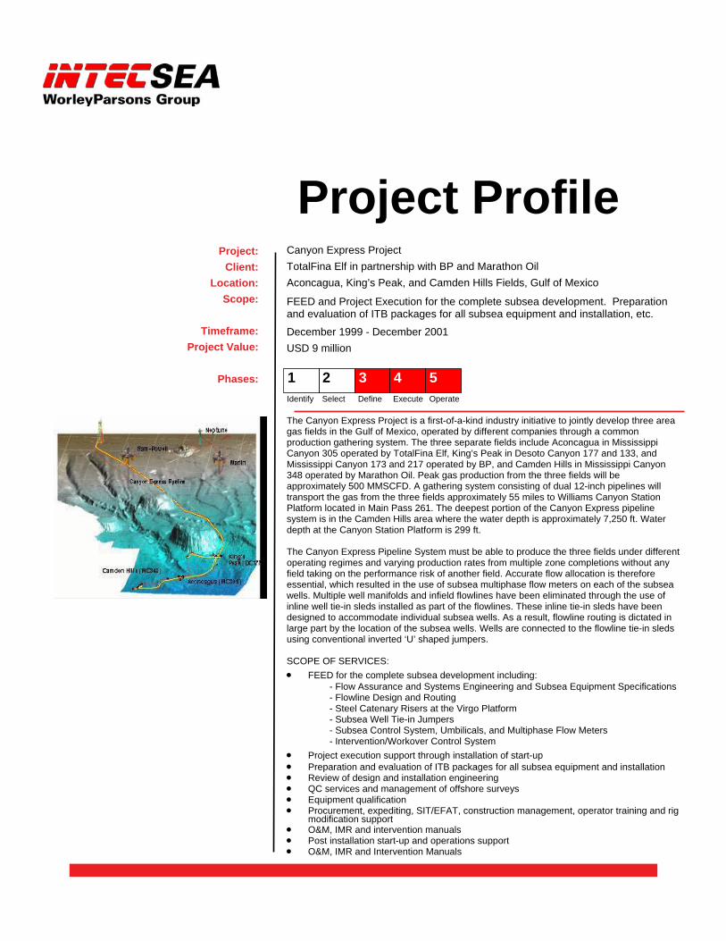
The Canyon Express Project is a first-of-a-kind industry initiative to jointly develop three area gas fields in the Gulf of Mexico, operated by different companies through a common production gathering system. The three separate fields include Aconcagua in Mississippi Canyon 305 operated by TotalFina Elf, King’s Peak in Desoto Canyon 177 and 133, and Mississippi Canyon 173 and 217 operated by BP, and Camden Hills in Mississippi Canyon 348 operated by Marathon Oil. Peak gas production from the three fields will be approximately 500 MMSCFD. A gathering system consisting of dual 12-inch pipelines will transport the gas from the three fields approximately 55 miles to Williams Canyon Station Platform located in Main Pass 261. The deepest portion of the Canyon Express pipeline system is in the Camden Hills area where the water depth is approximately 7,250 ft. Water depth at the Canyon Station Platform is 299 ft. The Canyon Express Pipeline System must be able to produce the three fields under different operating regimes and varying production rates from multiple zone completions without any field taking on the performance risk of another field. Accurate flow allocation is therefore essential, which resulted in the use of subsea multiphase flow meters on each of the subsea wells. Multiple well manifolds and infield flowlines have been eliminated through the use of inline well tie-in sleds installed as part of the flowlines. These inline tie-in sleds have been designed to accommodate individual subsea wells. As a result, flowline routing is dictated in large part by the location of the subsea wells. Wells are connected to the flowline tie-in sleds using conventional inverted ‘U’ shaped jumpers. SCOPE OF SERVICES: • FEED for the complete subsea development including: - Flow Assurance and Systems Engineering and Subsea Equipment Specifications - Flowline Design and Routing - Steel Catenary Risers at the Virgo Platform - Subsea Well Tie-in Jumpers - Subsea Control System, Umbilicals, and Multiphase Flow Meters - Intervention/Workover Control System • Project execution support through installation of start-up • Preparation and evaluation of ITB packages for all subsea equipment and installation • Review of design and installation engineering • QC services and management of offshore surveys • Equipment qualification • Procurement, expediting, SIT/EFAT, construction management, operator training and rig
modification support • O&M, IMR and intervention manuals • Post installation start-up and operations support • O&M, IMR and Intervention Manuals
Project Profile Canyon Express Project TotalFina Elf in partnership with BP and Marathon Oil Aconcagua, King’s Peak, and Camden Hills Fields, Gulf of Mexico
FEED and Project Execution for the complete subsea development. Preparation and evaluation of ITB packages for all subsea equipment and installation, etc.
December 1999 - December 2001 USD 9 million
Project: Client:
Location: Scope:
Timeframe:
Project Value:
Phases: 1 2 3 4 5 Identify Select Define Execute Operate
22
Project Management
WorleyParsons maintains a comprehensive suite of tools to manage projects at the highest level around the world. WorleyParsons employs a consistent, proven suite of group-wide processes, systems and tools supported by functional managers (Business Process Owners, or BPOs) and Business Systems Groups (developers, trainers, start-up support, help desk, commercial agreements, etc) scalable for any size pro-ject.
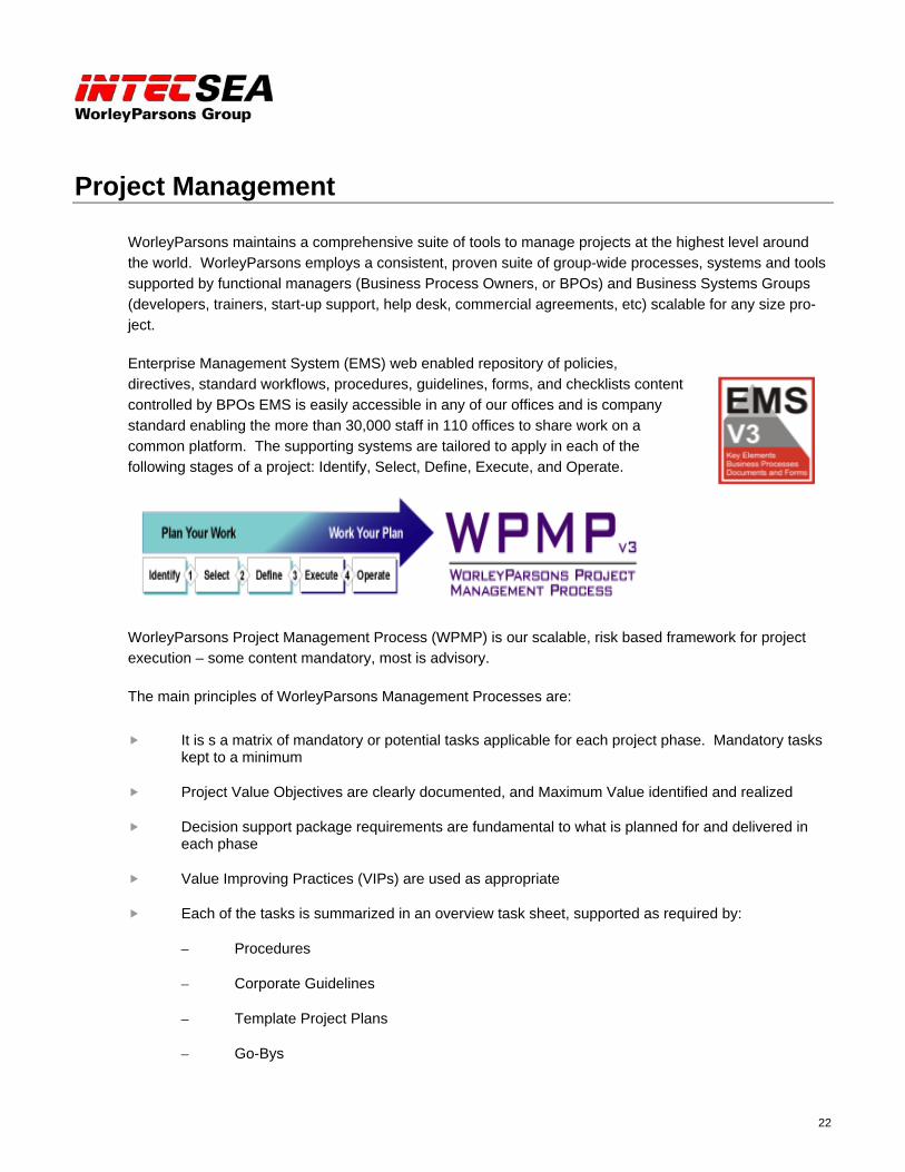
Enterprise Management System (EMS) web enabled repository of policies, directives, standard workflows, procedures, guidelines, forms, and checklists content controlled by BPOs EMS is easily accessible in any of our offices and is company standard enabling the more than 30,000 staff in 110 offices to share work on a common platform. The supporting systems are tailored to apply in each of the following stages of a project: Identify, Select, Define, Execute, and Operate.
WorleyParsons Project Management Process (WPMP) is our scalable, risk based framework for project execution – some content mandatory, most is advisory.
The main principles of WorleyParsons Management Processes are:
It is s a matrix of mandatory or potential tasks applicable for each project phase. Mandatory tasks kept to a minimum
Project Value Objectives are clearly documented, and Maximum Value identified and realized
Decision support package requirements are fundamental to what is planned for and delivered in each phase
Value Improving Practices (VIPs) are used as appropriate
Each of the tasks is summarized in an overview task sheet, supported as required by:
– Procedures
– Corporate Guidelines
– Template Project Plans
– Go-Bys

23
The system includes prompts and go-bys easily available for each phase of the work, illustrated by the following examples for Select Phase projects:
24
InControlInControl
InControl is our CTR based project cost and resources control tool - for small or large projects. It is WorleyParsons proprietary, but interfaces with third party applications plus selected third party applications under global agreements – Intergraph (PDS, Marian and SmartPlant Foundation), Primavera, Oracle, Quest, etc.
Other supporting systems include:
Primavera Project P3
– Project planning and control
Cost Management System (CMS)
– Estimating cost and schedule impact due to project changes
Scorecard
– Engineering progress measurement and productivity
Project Portal (EDMS)
– Secure, web-based, integrates closely with Microsoft Office 2003
– Data, schedules, and documents can be accessed from a central location by project teams, clients and vendors worldwide
Encompass®
– Total project management information tool
– Up-to-date and accurate information not only in the home office, but at the job site and at select partner or customers sites as well
– Information can be shared worldwide by project teams
25
Interface Management is one of the most critical management practices that must be performed to an excellence-in-execution result. Interface Management is core-defined as eliminating "the gaps and the overlaps.” In principle, Interface Management is clearly recognized by INTECSEA as a key active component of our Project Execution Plan.
The key is to recognize what information is required at what time by whom and where and to handle the constant flow of information, decisions, and requirements between all the stakeholders in the project. To this effect a common interface management process needs to be established among all parties; this requires that the interface management process is clearly identified as a contractual obligation between all parties.
There are multiple levels of information exchange:
Internal:
Between individual disciplines within Client team
Between Client team and contractors,
External:
Between the internal groups within the contractor
Between vendors, subcontractors, and 3rd parties and the main Contractor
Based on the experiences gained by INTECSEA, a methodology has been developed that suits most projects and applies to both internal and external interface management. The purpose of the IMS will be to maintain lines of communication between different stakeholders and Contractor(s) and, ensuring that technical details are consistent, schedule delivery dates are achieved and costs are kept within an agreed budget, as well as providing early warning to interfacing conflicts and tracking the effects of change.
26
The objectives of our Interface Management process are to:
Define the Information Exchange Requirements throughout all Phases of a Project
– General Project Information
– Equipment Interfaces
Information Required by Who and When
– Project Schedule and Milestones
– Deliverables
– Contractor Workscopes
Monitor the Exchange of Information
– Take Corrective Action through an Early Warning System
Excellent communication is of course an essential ingredient, but it needs to be accomplished in a systematic way to ensure interfaces are handled most effectively. Typically managing, coordinating and resolving interfaces are the role of an Interface Manager who reports directly to the Project Manager. His role is to systematically track the information exchange and its impact on progress.
INTECSEA’s Interface Management Process is a proven system tool to support the tracking, management, and effectiveness of the exchange of important project information.
Our IM system provides the following reports:
General Interface Information Reporting (general interface physical properties)
Interface Schedule Information Reporting (inter-related activities associated with search)
Interface Clarification Register (listing issues, date raised, due date, resolution)
Change Report (documenting the changes and the responsible parties)
Document and Drawing Register (listing project and ‘shadow’ document status)
INTECSEA personnel have been responsible for interfaces on a number of recent projects, such as the ChevronTexaco Agbami project. This major undertaking requires the management of over 85,000 interfaces between disciplines and contracts. The system was established during the FEED phase to coordinate the design effort and will continue throughout project execution phase to support management of the vendors and contractors.

27
The INTECSEA Interface Management System (IMS)
General interface information is organized on three working levels with increasing detail. It reports general interface physical properties for attributes, components and tasks. The system links with the project scheduling tools to identify impacts and monitor status. The Interface Clarification Register lists issues, dates raised and due, resolution, responsible party and resolution team. The change report documents changes to interfaces, tasks and milestones. The Document and Drawing Register lists current document and "shadow" document status.
A graphical interface, an example of which is shown in Figure 1 below, enables ease in finding related interfaces and facilitates coordination among the project participants.
INTECSEA IMS Concept Presentation
Figure 1: Graphical Interface on Typical Multi-Faceted Development
28
Effective interface management is key to the successful delivery of FEED and Detailed design. An Interface Management System (IMS) will be established during the FEED phase to identify and define design and disciplines interfaces and then continue through project execution to coordinate multiple contracts and suppliers.
The purpose of the IMS will be to maintain lines of communication between different disciplines, groups, companies, and contractors to ensure that technical details are consistent, schedule delivery dates are achieved, and costs are kept within an agreed budget, as well as providing early warning to interface issues and a mechanism for resolving.
Interfaces are either internal (within a defined component, assembly, or work scope) or external (between components, assemblies, work scopes, or organizations). As the project advances into the FEED, detail design, and execution phases, the management of external interfaces becomes more important and complex.
INTECSEA has developed an Interface Management System (IMS) methodology consisting of procedures, work processes and computer tools. The model is applicable to both internal and external project interfaces and can be adapted to suit any size or type of single or multi-faceted project. The Interface Management System (IMS) was developed by INTECSEA and incorporates the necessary procedures, work processes and computer tools to aid in the management of project interfaces. INTECSEA is currently providing complete interface management of ChevronTexaco’s Agbami project, a major project including an FPSO, subsea, flowlines and offloading. Initially, the system was applied to the substantial engineering tasks and will continue into management of the multiple EPC contract elements of the project.
The Interface Management Tool (IM Tool) is a robust database application accessible worldwide though the intranet. It stores and manages project interface information as well as interface links and key dates. Parties receive notifications of interface queries and actions by email, and can use the web interface to respond.
INTECSEA will offer Client the Interface Management System (IMS) modified to suit the particular needs of the project, including both internal and external interface management, and with suitably experienced engineers. The full IMS package will ensure that interface issues are identified and discussed between all affected parties.
The IMS will control the following aspect of the project:
Contractual responsibilities and requirements
Engineering tasks and activities
Design reports issue and revision dates
Interface physical properties
Project milestones
29
Procurement
Construction
Installation and commissioning
Operation and Maintenance
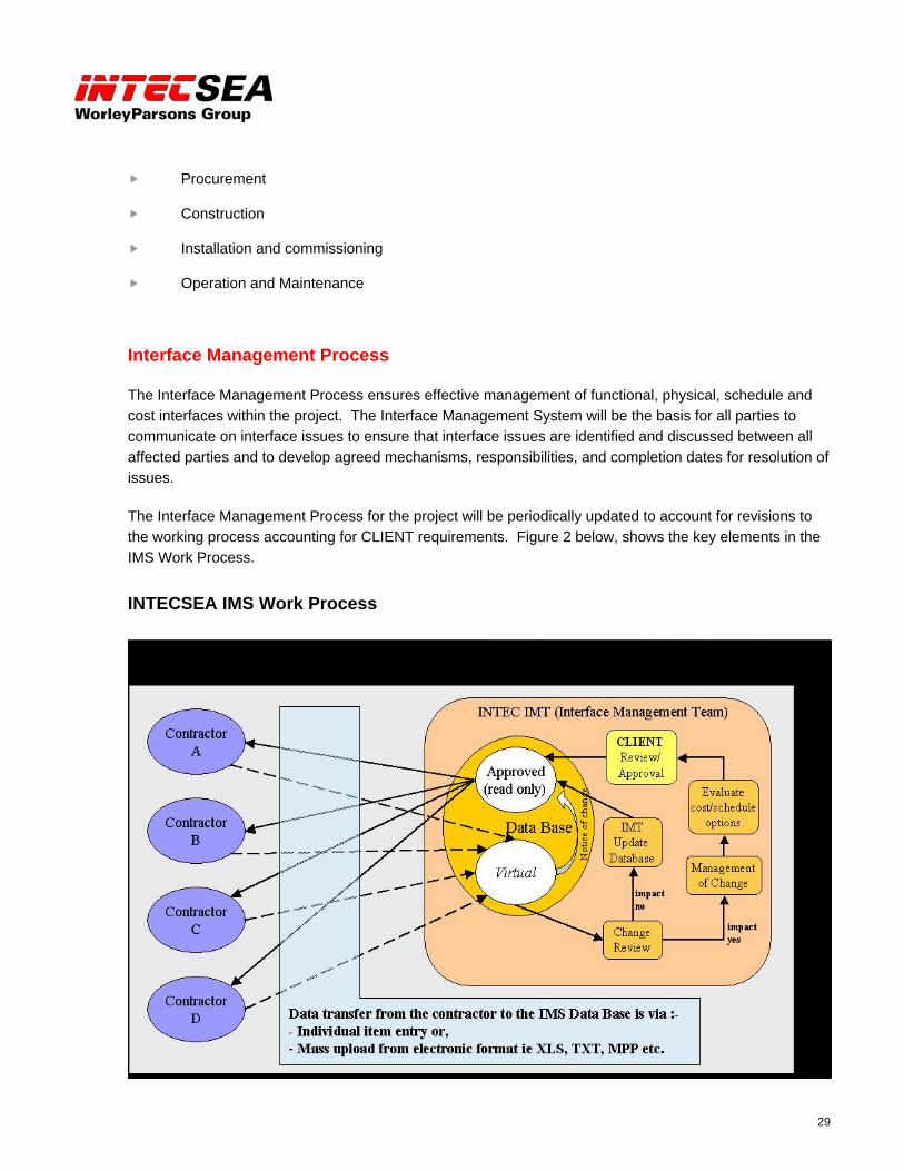
Interface Management Process
The Interface Management Process ensures effective management of functional, physical, schedule and cost interfaces within the project. The Interface Management System will be the basis for all parties to communicate on interface issues to ensure that interface issues are identified and discussed between all affected parties and to develop agreed mechanisms, responsibilities, and completion dates for resolution of issues.
The Interface Management Process for the project will be periodically updated to account for revisions to the working process accounting for CLIENT requirements. Figure 2 below, shows the key elements in the IMS Work Process.
INTECSEA IMS Work Process
30
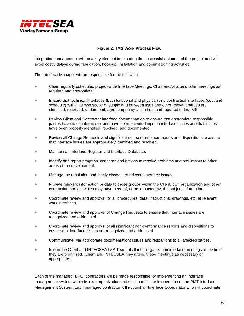
Figure 2: IMS Work Process Flow
Integration management will be a key element in ensuring the successful outcome of the project and will avoid costly delays during fabrication, hook-up, installation and commissioning activities.
The Interface Manager will be responsible for the following:
Chair regularly scheduled project-wide Interface Meetings. Chair and/or attend other meetings as required and appropriate.
Ensure that technical interfaces (both functional and physical) and contractual interfaces (cost and schedule) within its own scope of supply and between itself and other relevant parties are identified, recorded, understood, agreed upon by all parties, and reported to the IMS.
Review Client and Contractor interface documentation to ensure that appropriate responsible parties have been informed of and have been provided input to interface issues and that issues have been properly identified, resolved, and documented.
Review all Change Requests and significant non-conformance reports and dispositions to assure that interface issues are appropriately identified and resolved.
Maintain an Interface Register and Interface Database.
Identify and report progress, concerns and actions to resolve problems and any impact to other areas of the development.
Manage the resolution and timely closeout of relevant interface issues.
Provide relevant information or data to those groups within the Client, own organization and other contracting parties, which may have need of, or be impacted by, the subject information.
Coordinate review and approval for all procedures, data, instructions, drawings, etc. at relevant work interfaces.
Coordinate review and approval of Change Requests to ensure that interface issues are recognized and addressed.
Coordinate review and approval of all significant non-conformance reports and dispositions to ensure that interface issues are recognized and addressed.
Communicate (via appropriate documentation) issues and resolutions to all affected parties.
Inform the Client and INTECSEA IMS Team of all inter-organization interface meetings at the time they are organized. Client and INTECSEA may attend these meetings as necessary or appropriate.
Each of the managed (EPC) contractors will be made responsible for implementing an interface management system within its own organization and shall participate in operation of the PMT Interface Management System. Each managed contractor will appoint an Interface Coordinator who will coordinate
31
issue resolution activities within their organization and will communicate these resolutions to the PMT Interface Manager. The Interface Coordinator shall be a single-point-of-contact on the managed contractor’s interface issues. Each contractor shall establish within its own organization an interface management system to:
Ensure that technical interfaces (both functional and physical) and contractual interfaces (cost and schedule) within its own scope of supply and between itself and other relevant parties are identified, recorded, understood, agreed upon by all parties, and reported to the IMS.
Manage the resolution and timely closeout of relevant interface issues.
Provide relevant information or data to those groups within the contractor’s own organization, which may have need of, or be impacted by, the subject information.
Provide relevant information or data to other contracting parties and to the IMS, which may have need of, or be impacted by, the subject information.
Coordinate review and approval for all procedures, data, instructions, drawings, etc. at relevant work interfaces.
Coordinate review and approval of Change Requests to ensure that interface issues are recognized and addressed.
Coordinate review and approval of all significant non-conformance reports and dispositions to ensure that interface issues are recognized and addressed.
Reporting
Following resolution of an interface issue, the resolving party will provide appropriate documents, including Change Request and significant non-conformance review and actions, to the affected parties and to the Interface Manager for the record. The Interface Manager will record all agreements and actions in a suitable form and other appropriate documentation, as required. Systems Interface information shown in the form(s) will also be tracked in a database to provide ready access to the data developed. A sample of typical IMS report is shown below.
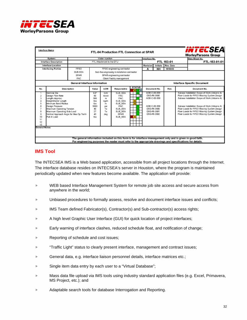
32
IMS Tool
The INTECSEA IMS is a Web based application, accessible from all project locations through the Internet. The interface database resides on INTECSEA’s server in Houston, where the program is maintained periodically updated when new features become available. The application will provide:
WEB based Interface Management System for remote job site access and secure access from anywhere in the world;
Unbiased procedures to formally assess, resolve and document interface issues and conflicts;
IMS Team defined Fabricator(s), Contractor(s) and Sub-contractor(s) access rights;
A high level Graphic User Interface (GUI) for quick location of project interfaces;
Early warning of interface clashes, reduced schedule float, and notification of change;
Reporting of schedule and cost issues;
“Traffic Light” status to clearly present interface, management and contract issues;
General data, e.g. interface liaison personnel details, interface matrices etc.;
Single item data entry by each user to a “Virtual Database”;
Mass data file upload via IMS tools using industry standard application files (e.g. Excel, Primavera, MS Project, etc.); and
Adaptable search tools for database Interrogation and Reporting.