Embed Size (px)
Citation preview

N A S A
L n M 40 M
= z c
I
4 c/) 4 z
T E C H N I C A L NOTE NASA TN D-3635
FLOW AND PRESSURE FIELD ANALYSIS OF PARALLEL GROOVE GEOMETRY FOR AN INCOMPRESSIBLE FLUID WITH CONVECTIVE INERTIA EFFECTS
by John Zuk? Lawrence P. Ludwig? and Robert E. Johnson
Lewis Research Center , r . *

TECH LIBRARY KAFB. NM
FLOW AND PRESSURE FIELD
ANALYSIS O F PARALLEL GROOVE GEOMETRY FOR AN
INCOMPRESSIBLE FLUID WITH CONVECTIVE
INERTIA E F F E C T S
By John Zuk, Lawrence P. Ludwig, and Rober t L. Johnson
Lewis R e s e a r c h Cen te r Cleveland, Ohio
NATIONAL AERONAUTICS AND SPACE ADMINISTRATION
For sale by the Clearinghouse for Federal Scientific and Technical Information Springfield, Virginia 22151 - Price $2.00

FLOW AND PRESSURE FIELD ANALYSIS OF PARALLEL GROOVE GEOMETRY
FOR AN INCOMPRESSIBLE FLUID WITH CONVECTIVE INERTIA EFFECTS
by J o h n Zuk, Lawrence P. Ludwig, and Robert L. Johnson
Lewis Research Center
SUMMARY
A set of two-dimensional equations that includes both convective inertia and viscous The equations are solvable for forces were formulated for parallel groove geometries.
the velocity and pressure distribution and optimum geometry by using numerical methods on a high-speed digital computer.
The mathematical model consisted of a smooth flat plate moving relative to a fixed parallel groove-ridge surface; both the smooth plate and the grooved plate were of infi- nite horizontal extent with the clearance filled with an incompressible, viscous, homo - geneous, isothermal, Newtonian fluid. A modified Reynolds number evolved that is based on a groove-ridge characteristic length parallel to the smooth plate velocity vector. analysis revealed that convective inertia can only be neglected if the modified Reynolds number is much less than 1 (creeping flow regime).
reveals that a significant improvement in bearing number o r sealing coefficient occurred when the modified Reynolds number w a s near 1. bearing number or sealing coefficient had previously been attributed to the onset of tur - bulence; therefore, it is argued that the strong influence of convective inertia, and not turbulence, is the main cause of this improvement.
The consideration of convective inertia effects reveals that fluid density p , aspect ratio b/ho, and number of groove-ridge pairs N are additional parameters of pressure generation dependence that are not implied in the creeping flow analysis.
The analysis presented herein provides a unified approach to parallel groove opera- tion, which w a s previously covered by the creeping flow analysis and a seniienipirical turbulent flow analysis. smooth and grooved plates. to hydrodynamic seals, bearings, and pumps. permissible in solving the equations. the principle of viscoseal axial pressure generation and attainment of zero leakage.
The
Application of the modified Reynolds number to four published experimental results
The detectable improvement in the
N o restriction w a s placed on the net flow situation between the
An arbitrary groove -ridge shape i s also Therefore, the analysis and resulting equations apply equally
Consideration of convective inertia effects explains

. I.. .I I .... .I. I . ...-
INTRODUCTION
The parallel groove geometry has many potential applications for use as a pressure generation device. thrust bearings (ref. l), spherical and conical spiral groove bearings (ref. l), helical groove pumps (ref. 2), and helical groove seals (viscoseal, see ref. 3).
The latter device (viscoseal) is potentially useful for sealing liquid metals, such as mercury, potassium, and sodium, in space electric power generation systems that r e - quire 1 to 3 years of unattended operation and near zero leakage (refs. 4 and 5). As pointed out in references 5 and 6, the viscoseal has inherent reliability and long life because of the absence of solid surfaces in rubbing contact.
ing capacity than the step or tilting pad bearings. An analysis of the helically grooved herringbone journal bearing is found in reference 7 for a perfect gas including the effects of small eccentricities. However, an infinite number of groove-ridge pairs was assumed for a finite-diameter journal bearing model in order to make the pressure gradients (which a re discontinuous at the groove -ridge interface) a smooth varying function.
To date, analyses of parallel groove geometry have been limited to creeping flow solutions where convective inertia effects have been neglected. fluid mass acceleration due to a spatial velocity change, for example, a change in ve- locity due to an obstacle in the flow path. by a temporal velocity change, for example, a variation in velocity at a point in a bearing
For example, the parallel groove has been applied in spiral groove
The analysis of the spiral groove bearing in reference 1 indicates a higher load carry-
Convective inertia is the
This is contrasted to an inertia effect caused
due to shaft runout. Reynolds number is
The creeping flow analysis is restricted to flows where the modified much less than 1; that is,
2 R8 = ReL(:) << 1
or
* Re I 0.01
where
UL pUL V P ReL = - =-
C - < 1
2

Creeping flow analyses for pumps, screw extruders, seals, and thrust and journal bearings have been published by many authors (e. g . , refs. 1 to 26). In appendix B is given an outline and discussion of the published creeping flow solutions. The main criticism of the creeping flow solution (generally used in the laminar flow regime) is that its validity is restricted to Reynolds numbers below most engineering applications and that zero net flow (seals) enters the analysis as an a priori assumption.
for the operational region beyond the creeping flow regime (turbulent regime), but they provide no insight on the effect of various parameters and give no formal approach to optimization of the geometry. The main criticism of these semiempirical analyses is that the existance of the turbulent regime is assumed; in short, turbulence is not neces- sary to explain reported experimental results and may not even exist. Even if turbulence does exist, convective inertia effects are thought to be f a r more significant. Kettleborough (ref. 29) numerically analyzed the slider bearing with inertia, turbulent, and viscous terms considered. When inertia only was considered, the results were in qualitative agreement with published (turbulent-attributed) slider bearing experimental results. Kettleborough concluded that the turbulence term did not greatly affect the operation of the slider bearing.
Golubiev (ref. 24) applied centrifugal pump similarity laws to the helical groove seal. This case considers an inviscid fluid whereby the pressure generation is found from Bernoulli's equation where A P varies as the square of the velocity. Due to the flow being in a confined space, and since the viscous force contributes to maintaining the gen- erated pressure gradient, the viscous force cannot be neglected.
Unfortunately, the creeping flow optimum geometry has been extended, almost universally, to be valid for operation beyond the creeping flow regime. Since the convec- tive inertia force is the main driving force, a complete reevaluation of the optimum geometry including the groove -ridge shape must be investigated before conclusions on viscoseal performance can be made.
parallel groove geometries by including convective inertia effects. Since the groove steps cause convective acceleration effects of the fluid, the edges of the grooves are not ne- glected. A flat-plate model of infinite horizontal extent will be analyzed. This is a rea- sonable physical approximation because the film thicknesses (clearance gap between two relatively moving surfaces) are usually very small in comparison to the radius of curva- ture and the circumferential length of the pump, bearing, and seal rotors (screw ex- truders may be an exception to this). The significant te rms for the study are found by a formal ordering procedure and by examining the physics of the problem. neglected because this is an infinite flat-plate case. (Refer to refs. 1 and 30 for creep- ing flow end effects and ref. 6 for experimental investigation of end effects. )
A number of semiempirical formulations have been devised (refs. 4, 18, 27, and 28)
The objective of this report is to examine the flow field and pressure generation in
End effects are
3

No restriction is applied as to net flow within the parallel groove geometry; there- fore, the analysis applies to hydrodynamic seals, bearings, and pumps.
SYMBOLS
a
b
cP c
FX
FY
Fz G
hO
k
L
L'
N
n
A P
P*
pC
Pr
Q
Qt
Qv R
Re
Re*
ridge o r land width
groove width
specific heat of fluid at constant pressure
clearance between ridge and smooth flat plate, or radial clearance
body force in x-direction
body force in y-direction
body force in z -direction
dimensionless factor, function of helical geometry
step or edge height
thermal conductivity of fluid
characteristic length, length of groove-ridge pair in smooth plate relative ve- locity vector direction
axial length, normal to plate velocity
number of helix starts
integer
pressure differential
static pressure at reference state
static cavity pressure
Prandtl number
net volume flow rate
volume flow rate in plate relative velocity direction
volume flow rate normal to plate relative velocity direction
radius of rotor
Reynolds number
modified or reduced Reynolds number
4
T* t
U
U
V
T
vP, X
vP, V
W
X
Y
Z
CY
f;
11
A
X G
E.r
V
V*
5 P
P*
a
V
V2
temperature at reference state
time
smooth flat -plate velocity
velocity in x-direction
characteristic velocity in the y -direction
fluid velocity vector
pressure flow velocity in x-direction
pressure flow velocity in z direct ion
velocity in y -direction
velocity in z -direction
coordinate along ridge -groove
coordinate across film (between plates)
coordinate across ridge -groove
angle between relative velocity direction and parallel groove -ridges or helix angle
film height
coordinate normal to plate relative velocity vector
bearing number
empirical sealing parameter (defined in ref. 5)
absolute viscosity of fluid
kinematic viscosity of fluid
kinematic viscosity of fluid at reference state
coordinate in direction of plate relative velocity vector
density
density at reference state
shape parameter
vector differential operator Del or Nabla
Laplacian operator
Subscripts:
C based on clearance or film thickness
5

g groove
L based on characteristic length
r ridge o r land
E plate relative velocity direction
normal to plate velocity direction (axial length)
BASIC MODEL
The rectilinear Cartesian coordinate system was selected for mathematical tract - ability. A parallel groove-ridge plate geometry with a smooth flat plate moving relative to the parallel groove-ridge plate, both of infinite horizontal extent, was chosen as the basic model (see fig. 1).
large diameter and a concentric grooved housing. Actually this infinite grooved plate model is the limiting case of a helical grooved cylinder where R - 03 or c - 0. If c/R I 0.01, this model should give a good qualitative picture of the flow field and pres- sure generation and significant trends for optimum geometry. For example, a practical
Conceptually this model can be thought of as an infinitely long smooth rotor with a very
m
m
(a) Plan view. I1 cin n
(b) Cross-sectional view along z-axis illustrating relative motion of smooth flat plate with respect to fixed parallel groove-ridge plate.
Figure 1. - Mathematical model of parallel groove-ridge geometry of infinite horizontal extent.
6
Cavity pressu ri
Pressurc
High sure
pres- end
End effect - Homogeneous f lu id
Liquid-gas mixture
- Scavenging or nonwetted region
Average pres- sure ridge leading edge
Average pres- sure ridge trai l ing edge
--
,,, .Ambient pressure
Axial distance l i
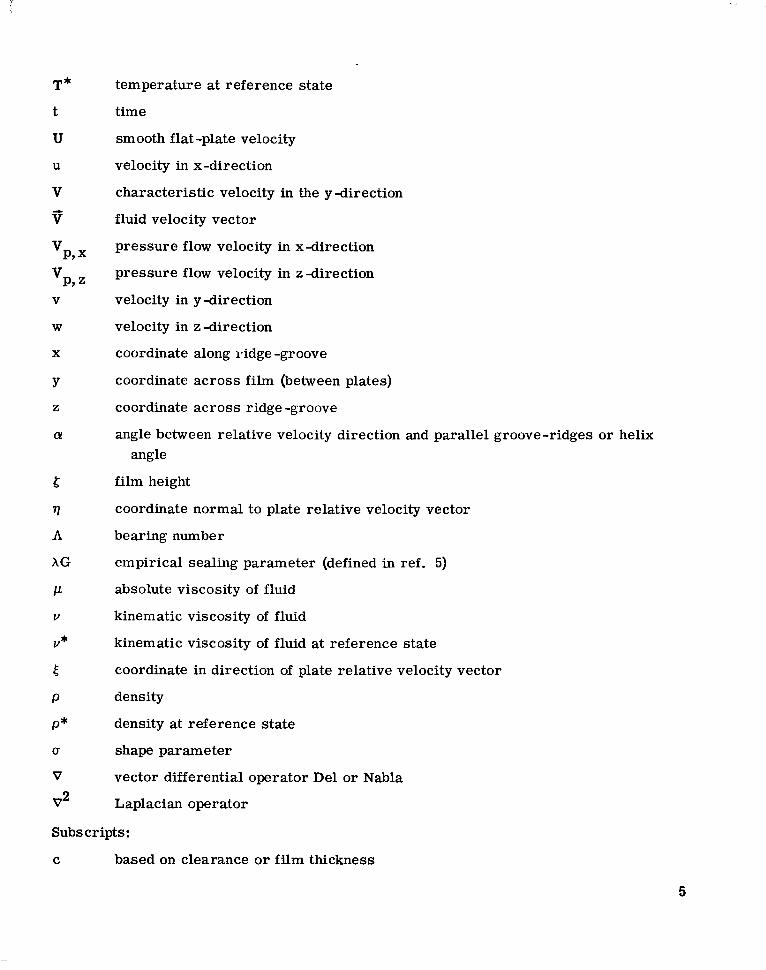
C-66-2693 Figure 2. - Region of analysis validity (homogeneous fluid) of a grooved housing viscoseal. Reynolds-
number based on clearance or f i lm thickness, 1700; modified or reduced Reynolds number, 19; 400-microinch shaft rotational movement dur ing photographic exposure; shaft speed, 8000 rpm; sealed fluid, water.
7
High pres- sure end
Discontinuous f lu id f i lm I-- (mixed a i r and liquid)
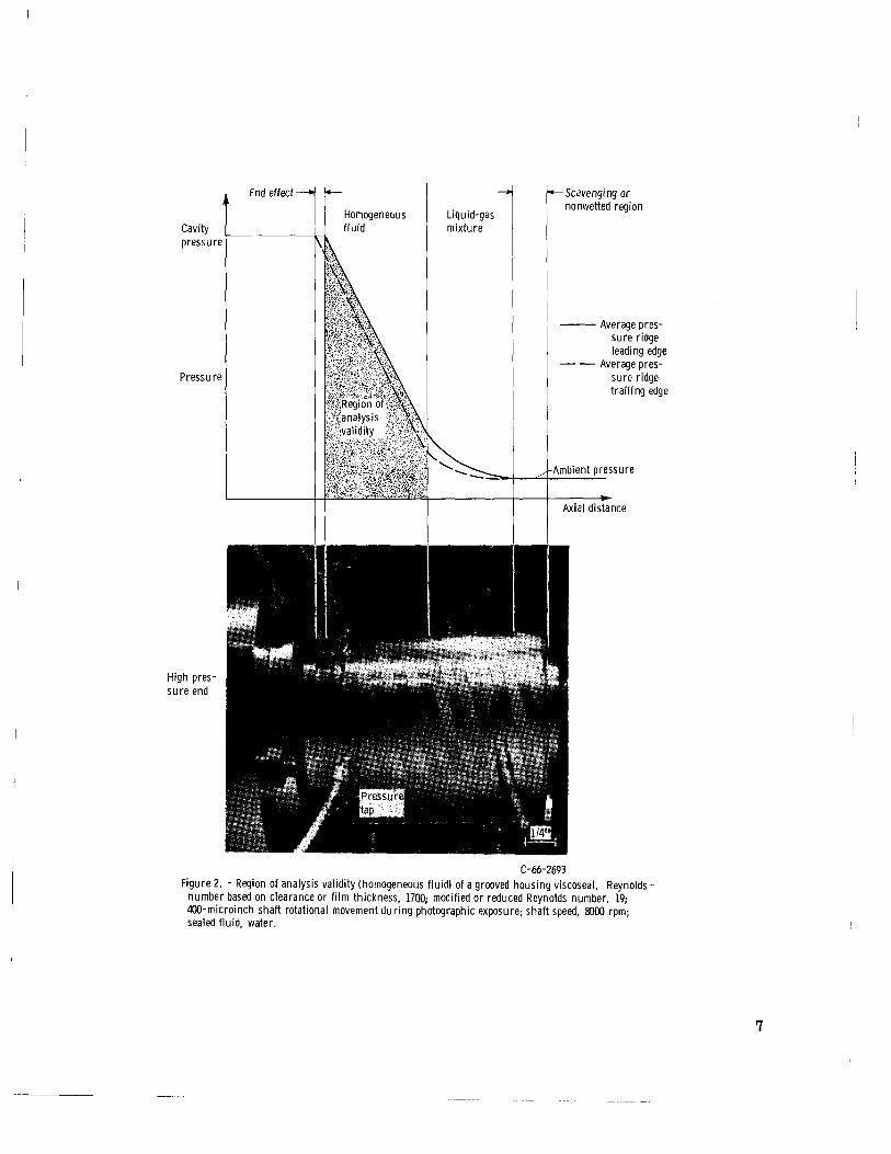
Figure 3. - Viscoseal wi th grooved housing operating in a regime of water-air mix- t u r e (gas ingestion). Analyses does not apply for th is discontinuous f lu id f i lm case; 250-microinch shaft rotational movement dur ing photographic exposure; shaft speed, 5000 rpm; sealed fluid, water.
geometry is a 2-inch-diameter rotor with a 0.005-inch concentric clearance, c/R = 0.005.
The clearance between the infinite plates is filled with any incompressible fluid, and it should be noted that for this infinite horizontal extent case there a re no end effects (in practical engineering design, of course, end effects must be accounted for). Since experiments at Lewis show that the end effect zone decreases with increasing rotor speed and also that it is less than a groove width, this analysis should be valid in the bulk of the homogeneous fluid (see figs. 2 and 3).
In the flat-plate case, the boundary conditions on a groove-ridge plate in motion a re constant; however, it will be advantageous to have the smooth flat plate move relative to the grooved flat plate. This will eliminate the temporal inertia terms and reduce the subsequent independent variables by one.
A word of caution for extension of the results to a case where the groove-ridge pairs on a finite shaft are rotating relative to a fixed smooth housing. The boundary conditions a re different when the smooth housing is stationary and the grooved rotor is moving, and when the housing is grooved and the rotating shaft is smooth. When the rotor is grooved, the surface speed is different at each point along the step or edge of the moving boundary. Thus this analysis should be more valid for a smooth rotor and grooved fixed housing (from ref. 5 the grooved housing appears to be the desired mode of operation) with a
8

large radius of curvature and/or small clearance.
groove -ridge pairs appear only in the y, z -plane. Later it will be shown that this choice of coordinate system will be necessary to reduce the analysis to a two-dimensional problem for the flow field. It should also be noted that the drag force has been resolved into its components in this coordinate system and there is no equilibrium of forces in the z -direction with inertia (nonlinear) effects neglected.
When referring to figure 1, it is noted that by the choice of coordinate system the
BAS IC EQUATIONS
The Navier -Stokes equations for a homogeneous, incompressible, laminar, Newtonian fluid are the following (see ref. 31): x -Direction:
y -Direction:
2 p - = F Dv Dt Y - - + p ( $ + $ + $ ) ap ay
z -Direction:
a w 2 a w 2 a w p Dw - = F, -" + /.L (y + T +:) az ax ay az Dt (3)
The Eulerian or spatial derivative is D/Dt, which is composed of the local acceleration (temporal velocity change) and the convective acceleration (spatial velocity change):
a a a a Dt a t ax ay az,
+ u -+ v -+ w - - - -- D
Local, ungteady, or ConveZtive nonstationary accel- acceleration eration
9

I 1 I 1 111 I 1 1 1 1 I 1 111
The incompressible continuity equation is
The assumptions for this analysis are as follows: (1) For steady flow,
(2) For no body forces,
Fx = Fy = Fz = 0
This means there are no electromagnetic fields present and gravitational effects are negligible.
(3) Isothermal and equal temperature plate surface conditions a re assumed. (4) Viscous (frictional) heating is negligible. Therefore, the thermophysical prop-
erties a re constant. This appears to be a good assumption for order ten (water) and smaller (liquid metals) Prandtl number Pr fluids:
cPp Pr = - k
In experimental setups there is an inherent unsteadiness due to vibrations, shaft runout, and eccentricity of rotor with respect to housing and misalinement. These fac- tors will influence the degree of correlation between the analytical and experimental re- sults.
formal ordering procedure was used to determine the relative magnitude of the terms. Consequently, in a formal way the negligible terms were found (see appendix A).
The conservation of momentum and mass equations were nondimensionalized and a
An important parameter, the modified or reduced Reynolds number, was found:
2 Re* = ReL(:) = Re C L (4) if c/L < 1
10

This modified Reynolds viscous forces; that is,
number gives the relative magnitude of the inertia forces to the
* Inertia forces Viscous forces
Re =
Thus, inertia effects can be neglected only if Re* I 0.01
field equations are a s follows: C ons e rvation of momentum :
After the formal ordering procedure (see appendix A), the three-dimensional flow
2 (x -direction) au au au 1 ap a u
ax ay az p ax u - + v - + w - = - - - + I / -
aY2
ap a Y - _ - 0 (y -direction)
2 (z -direction) aw 1 ap a w
+ u - u - + v - - + w - = - - - aw aw I . . . .. . .
aY2 ax ay az p az
Conservation of mass:
-c
Fully developed flow is assumed in the x-direction. This means that V and aP/ax are not functions of x and that the pressure gradient in the x-direction (parallel to the groove) is a constant (verified experimentally in r e f . 5). In figure 2, it is observed that this assumption is valid only where the pressure profile at the ridge leading or trailing edges in the axial direction is linear. Gas ingestion results in a nonlinear profile (see figs. 2 and 3).
direction), the flow field equations become two-dimensimal: With the assumption of fully developed flow along the groove-ridge direction (x-
2 where ap = constant v - + w - = - - - + v - au au l a p a u
ay az p a x ax aY2 (9)
11
I I
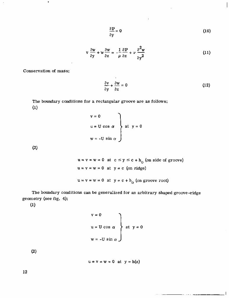
Conservation of mass:
The boundary conditions for a rectangular groove are as follows:
(1)
a J w = -u sin
u = v = w = 0 at c 5 y 5 c + ho (on side of groove)
u = v = w = 0 at y = c (on ridge)
u = v = w = 0 at y = c + ho (on groove root)
The boundary conditions can be generalized for an arbitrary shaped groove-ridge geometry (see fig. 4):
(1)
at y = 0 1 v = o
u = u cos CY
w = - u s i n a
u = v = w = O at y = h ( z )
12

Equations (9) to (12) can be reduced in terms of the dependent variables u, v, and w by vanishing the pressure terms. The pressure terms vanish when differentiating equations (9) and (11) with respect to y and when noting that aP/ay = 0 (eq. (10)). In the process the order of the equations is increased by one. The x-direction momentum equation becomes
Figure 4. - Cross-sectional view along z-axis illustrating arbitrary groove-ridge pair shape.
2 2 3 (13)
av au aw au a n a u a u ay ay ay az ayaz ay2 ay3
+ - -+w- + v - = v - --
The z -direction momentum equation becomes
3 a W av aw aw aw a w a w
ay ay ay az ayaz 2 3 a Y a Y
2 2 +- - + w - + V - - - v - --
Since the continuity equation remains the same,
then the z -direction momentum equation becomes
2 2 3 a w a w a w ayaz ay2 ay3
w- + v - = v -
These equations (12), (13), and (15) can be solved for the velocity components. Once the velocity components have been obtained, the pressure gradients can be found from equations (9) and (11). Then the axial pressure gradient aP/aLf can be found from
ap - ap sin a + ( E ) ~ + ~ cos a! a v ax
where L' is the axial length (see fig. 5). Pressure distribution in the x- and z-directions is shown in figures 6 and 7. tions, the axial pressure gradient aP/aL' is a function of (a, U, p, v), where u is a
Therefore, by examining the analysis and the derived equa-
13

I
Figure 5. - Resolution of across and along groove-ridge pressure gradients into axial oressure gradient.
Figure 6. - Pressure distribution over parallel groove geometry. (Qualitative graphical representation from experimental data. I
14
. . I

I I I -
n L cos a - Coordinate along ridge-groove, x
(a) Along ridges or grooves (no end effects are shown).
&
3 L
VI VI 2
E a
Reference pressure-*
- Groove Coordinate across ridge-groove, z
(b) Across ridges and grooves (no restric-
Figure 7. - Pressure profiles (qualitative graphical representation from experimental data).
tion that profile must be linear).
15

F
shape parameter that is a function of (b/ho, c/ho, a/b, a). Since convective inertia effects a r e important, new geometric parameters appear
which a re not implied in creeping flow theory. Most notable of these is the aspect ratio b/ho, which implies the degree of convective effect. When the b/ho and a/b ratios are known, N, the number of helix or groove starts, can be found. Thus the number of groove or helix starts also is an important parameter. Since inertia is important, a high density is desired for pressure generation.
DISCUSSION
Discussion of Equations
This analysis is valid only for a homogeneous fluid. Figures 2 and 3 clarify the region of validity. In some parallel groove geometries (e. g., the viscoseal) where there is a liquid-gas interface, there is a problem with gas ingestion (ref. 5). Gas ingestion, which is a condition of liquid and gas mixture throughout the seal, is shown in figure 3. The analysis is not valid for this condition because the fluid is nonhomogeneous. the analysis is not valid for a scavenging area and a region consisting of a mixture of gas and liquid (see fig. 2).
It should also be pointed out that the analysis is not valid in the end effect region at the high pressure end of the seal (see fig. 2) where the groove connects with the cavity. Since the appropriate equations a re nonlinear, the pressure is not a harmonic function; thus, the usual analog methods of finding end effect are not available as found in creeping flow regions (see appendix B).
duced to two dimensions (y - and z -directions) but all three velocity components are present. Also, there is a pressure gradient in the third dimension (x-direction), but fortunately this gradient is a constant.
tion. Physically, v cannot be negligible because of the presence of the edge effect which will result in a component of velocity in the y-direction.
equations should equally apply to hydrodynamic seals, bearings, and pumps.
groove -ridge pairs the unbalance of the convective acceleration force with the drag force results in a pressure gradient in the z-direction. Since the step or edge causes the con- vective acceleration, its effects a r e not negligible unless there is a very large aspect ratio and the mathematical model accounts for the edge effect. Along the groove and
Further,
The equations a re unique in many ways. Mathematically, the problem has been r e -
The velocity component v is no longer negligible as it was in the creeping flow solu-
Since there is no restriction on net volume flow, the pressure generation prediction
When further examining the physics of the problem, it is seen that across the
16

ridge (x-direction) the drag force is in equilibrium with the induced pressure and con- vective inertia force. The drag force not only causes fluid motion but also aids in main- taining equilibrium with the pressure along the groove or ridge.
inertia terms. In creeping flow there is no coupling between the velocity components, which illustrates the shortcoming of that analysis (i. e., end leakage is not zero).
sults in equations of the boundary layer type; however, the boundary conditions are dif- f e rent.
variables by one by trying to find the admissable flow field which would result in a similarity transform solution. This technique fails because of the characteristic lengths that are present in this type of confined flow.
The equations are solvable by using high-speed digital computer numerical methods. A mathematical function to describe the groove-ridge shape would be too complex for a closed-form analytical solution. It should be interesting to find out if the step is still the optimum shape with convective inertia effects included. For creeping flow, Lord Rayleigh found in 1912 that the step was the optimum shape by using calculus of varia- tions.
ing these results beyond the assumptions used in this analysis.
Both equations of motion illustrate the coupling of u, v, and w in the convective This means that physically a condition such as no end leakage is possible.
The assumption that the inertia terms a r e of the same order as the viscous terms re-
The equations are of a form that might tempt one to reduce the number of independent
The equations and ordering procedure should be reexamined carefully before extend -
Discuss ion of Modif ied Reynolds Number
A check was made on the significance of the modified o r reduced Reynolds number by calculating Re* from the available published data at the claimed onset of turbulence (break point). In table I it can be noted that the departure in all cases from a constant sealing coefficient occurred when Re* was in the range of 0. 26 to 2. 2, which suggests that the so-called beginning of turbulent operation is really the beginning of significant convective inertia effects. This would be in agreement with Kettleborough (ref. 29), who found qualitative agreement between his inertia solution and experimental turbulent re - sults.
For seals 5, 6, and 7 (see ref. 27 and table I), only the groove to ridge ratio has changed. A s the ratio increases, the breakpoint decreases. This is reasonable since a larger ridge area results in a less influential convective inertia effect and delays the beginning of pronounced convective inertia effects. It can also be seen in table I that the calculated Re* are within an order of magnitude of one another for all of the experi-
17

!learance teynolds number,
Rec
Modified Reynolds number,
Re*
400 (b) (b) 3 50
1.7 (b) (b) .95
TABLE I. - CRTTICAL MODIFIED REYNOLDS NUMBER FOR ONSET OF TURBULENCE OF VARIOUS MPERTMENTERS
iidge vidth, a, in.
Groove width,
in. b,
ieference Seal Radial .learanc e,
c, in.
Ratio of radial
:learance to rotor radius
c/R
Jharacteristic length,
in. L,
Iiameter, in.
Experimenter
Stair
King
27 a1 2 2B 3 3B 4 4B 5 6 7
1.2430 1.2465 1.2420 1.2461 1.2408 1.2461 1.2408 1.2455 1.2455 1.2455
0.0042 ,00235 .0047 .00265 .0053 .00265 .0053 .00295 .00295 .00295
0.0068 .0038 .0076 .0043 .0085 .0043 .0085 .0047 .0047 .0047
3,0934 .1176 .1176 .0828 .0828 .0514 .0514 .1585
1.1596 .0494 ,0494 .Q842 .0842 .1156 .1156 .0607
4.5 9.67 9.67 9.67 9.67 9.67 9.67 5.81 5.81 5.81
1.01 .98 .98 .98 .98 .98 .98
1.83 1.83 1.83
3.2 3.2 1.54 1.54
. lo70 . lo83
.0609 .1600
4 and 27 3 c 2 1B 2 2E 2 5D 2
~~~ ~~ ~~
0.0029 0.0029 .0020 .0020 .0025 .0020 .0015 .0015
~
0.1063 0.1063 .lo63 .lo63 .loo0 .loo0 ,1000 .loo0
3.86 3.86 7.26 7.26
5 50 0.50 400 .25 650 1.1 6 50 .63
McGrew and 18 McHugh
SF96-5oil 1 0.00325 0.0065 (c) (c) 14.5 3.14 400 0.41
Configura- 2
Confiwra- 2 tion B
tion C
0.0032 0.0032
.0032 .0032
0.075 0.122 14.5 0.79 350 1.4
.083 .136 4 3.13 500 .51
Lessley 28
aEccentricity of rotor to housing, E = 0.1. *Break point not well defined. 'Four thread starts.

.I
m L .u a E .- w
t
Claimed creeping Turbulent flow regime flow regime (claimed by present
day researchers) I Re’:‘ Z 1,‘ - I
I Seal Width Radial Helix Eccentric
ratio, clearance, angle, rat io
in. deg bla c, a,
0 5 0.38 0.00295 5.81 0.3 A 6 1.0 .00295 5.81 . 3
Y
- . 80 100 160 200 400 600 800
Clearance Reynolds number
Actual region of creeping flow validity
.- V .- 8 1 c m
1000 2000
Figure 8. - Experimental sealing parameter for seals 5, 6, and 7 from reference 27.
Signif icant convective iner t ia effects
Generally accepted by cu r ren t researchers
Expected variation since iner t ia effects begin gradually
\-Breakpoint (onset of turbulence)
4000
menters. It is difficult, nevertheless, to select the breakpoint (see fig. 8). Even in a range of possible breakpoint numbers, however, the order of magnitude will r e - main the same. sults wi l l be necessary, but in general, it can be concluded that if Re* 2 1, a constant sealing coefficient o r bearing number will not exist.
the empirical sealing parameter IG was thought to be a constant until some critical Rec and then to vary exponentially in the turbulent regime. The creeping flow solu- tion was thought to be valid until the critical Re, and then a semiempirical turbulent theory had to be used. Actually, the onset of significant convective inertia should be gradual, as shown in figure 9. Data (from ref. 27) for seal 7 in figure 8 tends to show this. The derived equations herein pertain to all cases under the assumptions stated
Further experimental r e -
In figure 9 it is seen that classically
19
I

and will break down only under strong turbulence or an unknown instability pnenomena.
Pr inc ip le of Viscoseal Operation
The classical explanation of viscoseal operation is now described. Since the seal is t'pumping'' the sealed fluid as fast as it is leaking out, there is no net end flow (zero leakage). seal axial pressure gradient results from the unbalance of the convective inertia force across the groove-ridge pairs and the drag force. The convective inertia force is much greater than the opposing drag force and results in a net pressure force. Along the groove-ridge direction, the drag force maintains equilibrium with the pressure force and convective inertia force. All three velocity components are ?'coupled", and thus zero net leakage is achieved. This is an excellent example of the physical importance of a nonlinear effect. The inadequacy of the linear theory (creeping flow) has been previously discussed.
From the basic laws of fluid mechanics, however, it is seen that the visco- v
T
CONCLUDING REMARKS
A review of the literature on analysis of the parallel groove geometry revealed that either the convective inertia forces o r the viscous forces were neglected (inviscid fluid assumption). This analysis included both convective inertia and viscous forces. The following two-dimensional set of flow field equations were formulated and a re solvable for the velocity and pressure distribution and optimum geometry utilizing numerical methods on a high -speed digital computer:
Conservation of momentum :
ap ax - = constant
20
I
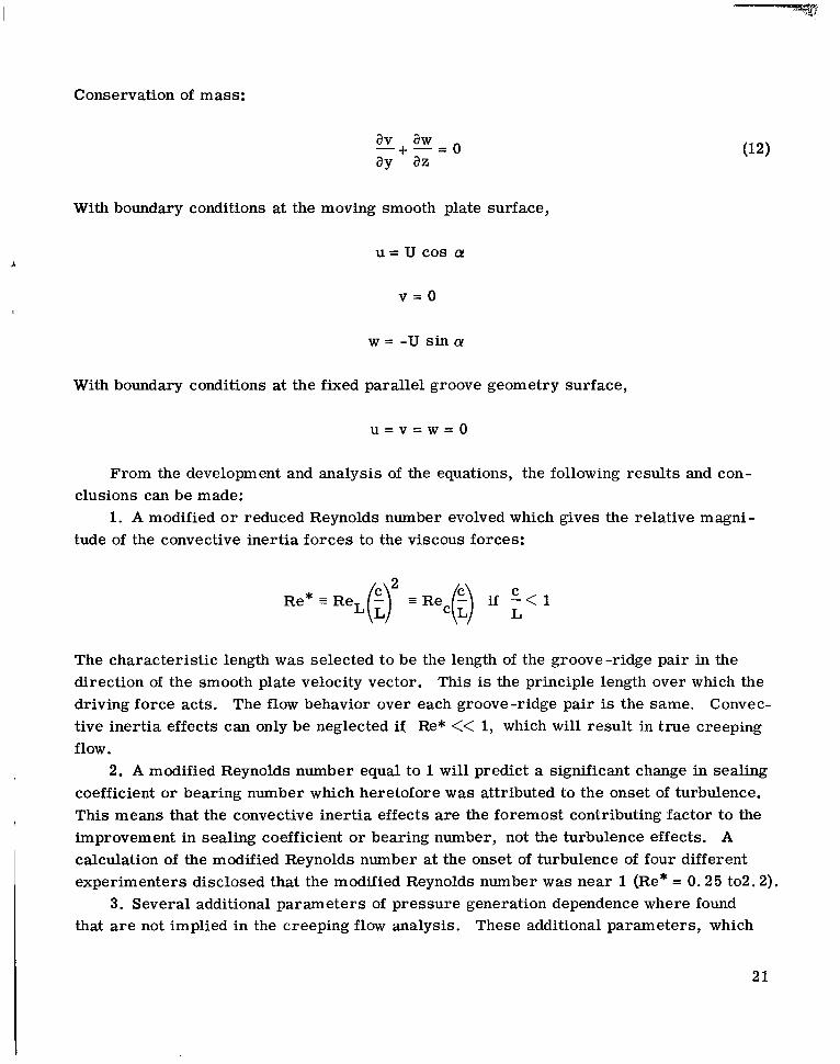
Conservation of mass:
With boundary conditions at the moving smooth plate surface,
u = u cos a!
v = o
w = -u sin (Y
With boundary conditions at the fixed parallel groove geometry surface,
From the development and analysis of the equations, the following results and con-
1. A modified o r reduced Reynolds number evolved which gives the relative magni- clusions can be made:
tude of the convective inertia forces to the viscous forces:
Re* = ReL(:y = Rec(:) if - C < 1 L
The characteristic length was selected to be the length of the groove-ridge pair in the direction of the smooth plate velocity vector. This is the principle length over which the driving force acts. tive inertia effects can only be neglected if Re* << 1, which will result in true creeping flow.
coefficient or bearing number which heretofore was attributed to the onset of turbulence. This means that the convective inertia effects a re the foremost contributing factor to the improvement in sealing coefficient or bearing number, not the turbulence effects. A calculation of the modified Reynolds number at the onset of turbulence of four different experimenters disclosed that the modified Reynolds number was near 1 (Re* = 0.25 to2.2).
3. Several additional parameters of pressure generation dependence where found that are not implied in the creeping flow analysis.
The flow behavior over each groove-ridge pair is the same. Convec-
1 2. A modified Reynolds number equal to 1 will predict a significant change in sealing
These additional parameters, which
21

Y
arise from convective inertia effects, are the fluid density p, the groove width to depth o r aspect ratio b/ho, and the number of groove-ridge pairs N.
arbitrary groove -ridge shape, for example, sinusoidal, rectangular, triangular, etc. (It is expected that the optimum groove-ridge geometry will be different from that found from the creeping flow solution. ) Now a check can be made to see if a step is the opti- mum shape with convective inertia effects as it is for creeping flow.
5. The analysis provides a unified approach to parallel groove operation previously covered by creeping flow (sometimes called laminar flow) analysis and a semiempirical turbulent flow analysis.
the analysis can be used to analyze parallel groove geometries in hydrodynamic seals, bearings, and pumps.
inertia force across the groove-ridge pairs and the drag force. Along the grooves or ridges, the drag force maintains equilibrium with the pressure force and the convective inertia force.
convective acceleration te rms (nonlinear effect). It is argued that the creeping flow analysis, which is a linear theory, cannot prove zero leakage.
effects in any step o r converging wal l hydrodynamic seal, pump, or bearing (Rayleigh step, journal bearing, etc. ) .
4. Solving equations (9) to (12) by numerical analysis will permit the investigation of
r 6. No restriction was placed on the net flow situation between the plates. Therefore,
7. The viscoseal axial pressure gradient results from the unbalance of the convective
8. Zero leakage in viscoseal analysis can be attained through the consideration of
9. The format of this analysis can be used to evaluate qualitative convective inertia
Lewis Research Center, National Aeronautics and Space Administration,
Cleveland, Ohio, June 26, 1966, 120-27-04-03-22.
22
APPENDIX A
FORMAL ORDERING PROCEDURE FOR SIMPLIFYING BASIC EQUATIONS
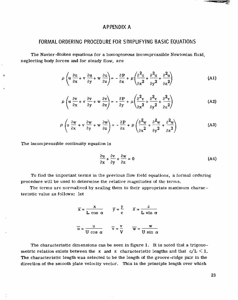
The Navier -Stokes equations for a homogeneous incompressible Newtonian fluid, neglecting body forces and for steady flow, a r e
au au p
The incompressible continuity equation is
To find the important terms in the previous flow field equations, a formal ordering procedure will be used to determine the relative magnitudes of the terms.
The terms are normalized by scaling them to their appropriate maximum charac- teristic value as follows: let
- X Z X = z =
y = % - L sin CY L cos CY
- v - W v = - W = U -
U = u cos a! V U sin a
The characteristic dimensions can be seen in figure 1. It is noted that a trigono- metric relation exists between the x and z characteristic lengths and that c/L < 1. The characteristic length was selected to be the length of the groove-ridge pair in the direction of the smooth plate velocity vector. This is the principle length over which
23

P
the driving force acts. The flow behavior over each groove-ridge pair is the same. Let p* and v* be the fluid density and viscosity corresponding to a reference state
(P*, T*). Therefore,
and
- P p = - = l P*
for incompressible fluids with constant thermophysical properties. Now to find the rel- ative magnitude of V so that all terms of the incompressible continuity equation will be of the same order, the incompressible continuity equation is nondimensionalized:
a i i v L av aw ax u c ay az -+ - - - + - = 0
To have all terms of the equation the same order of magnitude, - - must be of the order u c C V L
of 1. Therefore, V = U-, and thus V= - -. L u c
Next the equations of motion are nondimensionalized. The pressure term must first be nondimensionalized; even though the pressure is not the driving force, it is the func- tion of primary importance. Thus the characteristic pressure is not extremely impor- tant. Since the pressure gradient is related to the rotor speed, it appears to be logical to nondimensionalize the pressure with respect to the dynamic pressure pU (also called the dynamic head):
2
It can be seen that the characteristic dynamic pressure pU2 has reduced the num- ber of nondimensional groups by one (i. e., if P* (a reference pressure) had been used, another nondimensional group would be present in the equations). Also, since the incom- pressible case is being analyzed, the pressure appears in the dynamic role only, not in the thermodynamic role.
24
I 1 1 1 1 1 1 1 I 1 1 ~ 1 II I '

I
When the x-direction momentum equation is nondimensionalized, equation (1) re - sults in
- a i i -au - au 1 a@ v* a2u L a2u+ 1 a 2 7
sin 2 - 2 a! az u -+v-+w-=- - -
ax ay az cos 2 [Y a i + i i [ + a + ( ; ) COS [Y ax - a$
Next a Reynolds number is defined based on the characteristic length L: .k
UL 7 ReL = v*
where
and thus
- 2 & 1 a% a9 sin a az -
u - + v - + w -= - - 1 - ap +--- 1 [ i2 a:+(;) +-- - a i i -au - a i i 2 - 2 ax ay a?; cos a! ax re^ cos ax
The convective acceleration and pressure te rms are of unit order; thus, the viscous term must be of unit order also. The largest term of the viscous forces is -
2 2 t) a, since (:) < 1; therefore, the - (3" should be of unit order. The mod- ay2 ReL
ified Reynolds number is defined by Re* = ReL (k)2. This is the identical "reduced" or "effective" Reynolds number that is used in the bearing theory to show the true rel- ative magnitude of the inertia and viscous forces; therefore,
Inertia forces Viscous forces
Re* =
(e. g. , see ref. 31). Now for curved geometries, a Reynolds number based on clearance has appeared. This is especially true in viscoseal analysis where
u c Re, = - V
25
I

Writing the previous x-direction momentum equation in terms of Rec gives
u - a i i --+ v - a i i -+w - a i i = -- 1 -+ a5 - v* (c 1 a2i i + - - L a2i i +---) c 1 a% a x a y a z cos a! ax uc L c o s 2 a a 2 c $9 L s i n 2 a a$
or
- - a i i - a i i - a i i 1 a p 1 c 1 a 2 u L a2i i c u - + + - + + - = - -- + - - a x a y a z cos 2 Q! a x + & (E 2 COS Q! T ax c 87-2 L sinla a$
Again it is seen that the a 2 g a y 2 term is the largest. Thus l/Rec(L/c) should be of unit order. Now
Re* = Re (5) C L
which leads to
It does not matter which Reynolds number is used to find the relative inertia force to viscous force ratio provided that c/L < 1, which corresponds to the conditions
a 2 a 2 ay2 az 2 - >>-
and
a 2 a 2 a y 2 a x 2 ->> -
":
t
The proper x-direction momentum equation then becomes
26
I
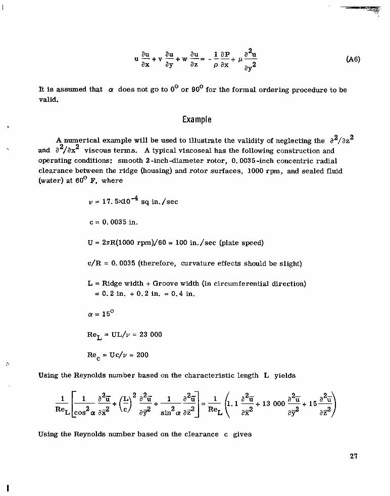
2 au au au 1 ap a u ax ay az p ax + P- u - + v - + w - = - - -
aY2
It is assumed that a! does not go to 0' or 90' for the formal ordering procedure to be valid.
Example i
A numerical example will be used to illustrate the validity of neglecting the a 2 2 /az +I and a 2 2 /ax viscous terms. A typical viscoseal has the following construction and
operating conditions: smooth 2 -inchdiameter rotor, 0.0035-inch concentric radial clearance between the ridge (housing) and rotor surfaces, 1000 rpm, and sealed fluid (water) at 60' F, where
v = 1 7 . 5 ~ 1 0 - ~ sq in./sec
c = 0.0035 in.
U = 2nR(1000 rpm)/6O = 100 in./sec (plate speed)
c/R = 0.0035 (therefore, curvature effects should be slight)
L = Ridge width + Groove width (in circumferential direction) = 0.2 in. + 0.2 in. = 0.4 in.
0 Q = 15
ReL = UL/v = 23 000
Rec = Uc/v = 200
Using the Reynolds number based on the characteristic length L yields
13 000 -+ a2i i a? -2 ax
Using the Reynolds number based on the clearance c gives
I
27

2- -2 In both equations it is seen that a d a y duced Reynolds number is
is the largest term. Now the modified or re-
2 Re* = ReL(:) = Re C L (’> = 1.75
Nondimensionalization of y- and z-Direction Momentum Equations
Nondimensionalizing the y -direction momentum equation (eq. (2)) yields
2 2- - av -av - av a v u - + v y + w - = - ax ay az
Again using the definition of Re* and comparing the largest t e rms give
and
Since
the ref ore
28

This result is expected for a flat plate where there is no mechanism to generate a radial pressure gradient (e. g., a centrifugal force). radial pressure gradient aP/ay should also be a small quantity and have little physical influence on the axial pressure gradient.
In a similar manner the z -direction momentum equation is nondimensionalized and the result is
For small curvatures, however, the
x
As expected, due to dimensions of the same relative size, the z-direction momentum equa- tion is the same as the x-direction momentum equation (eq. (6)), but the boundary condi- tions a r e different.
29

APPENDIX B
SUMMARY OF CREEPING FLOW ANALYSIS
The optimization from creeping flow analysis has been formulated by considering a
(1) General incompressible plane Couette flow is assumed in the <-direction flat-plate model (unwrapped cylinders, see fig. 10) and the following:
(Poiseuille flow and simple Couette flow). The < -direction momentum equation is
with the boundary conditions
u = U at g = O
u E = O at g = h
E
where
h = c at ridge surface
h = c c ho at groove root surface
The well known solution (e. g. , see ref. 31) is
m -m
Po 5 where P I > Po
Section A-A of groove-ridge pattern
Figure 10. - Model used in creeping flow solution.
Y,
,
u c E h 2 y d 5
(2) Poiseuille flow is assumed in the P
7-direction. The ?-direction momentum equation is 1 *
I a w 2 l a p
v - - -
with the boundary conditions
30

(High pressure) w = O at b = O
w = O at 5 = h
71 U, = 0.26 u
rl
The well known solution (see ref. 31) is (Low pressure)
/ y q Figure 11. - Resolution of plate velocity (or drag force)
into components along and across groove or ridge.
Now the condition Q = 0 is imposed in the control volume; that is,
which means that there is no net end leakage o r closed channel flow. This is a restr ic- tion that limits the optimization and pressure gradient prediction to a seal only.
a sealing parameter Solving for pressure gradient that satisfies the Reynolds equation (ref. 32) results in
A P 6pUG --- - 2 L' c
o r
1 2
where A is the bearing number (ref. 32) and G is a geometry factor. See references 1 to 26 for various expressions and values for G.
The creeping flow analysis has some paradoxes. It can best be illustrated by r e - ferring to figures 1 and 11 and by observing the resolution of the drag force into com- ponents along the groove (x-direction) and normal to the groove (z-direction). In creep- ing flow, the drag force is in equilibrium with the pressure force. Thus along the groove (x-direction) the drag force is indeed in equilibrium with the pressure force. In the normal groove direction (z-direction), however, the pressure and drag forces a re in the same direction, which is also the direction of a very large pressure gradient (see figs. 6 and 7 ) . Q = 0 restriction is not possible. Also, this point can be illustrated from 5- and q-direction momentum equations, respectively:
I
Therefore, an unbalance of forces exists in this direction. Physically, the
I 31

Notice that there is no velocity "coupling'? between the velocity components; that is, u a r e independent of one another. It is obvious that for zero leakage these velocity components are not independent of one another. Thus, physically as well as mathematically it is not possible under the restrictions of the classical creeping flow analysis to get zero leakage.
Also in the creeping flow analysis the edge effects are assumed negligible. The fu l l meaning of this assumption has not really been clarified; it is only close to physical reality when c is very small and/or b/ho is very large. For example, the creeping flow analysis is valid for spiral groove thrust bearings where c is on the order of 500 microinches and the aspect ratio is on the order of 1000 (c/L << 1, see fig. 12). As b - ho, the edge effect becomes more pronounced as the convective force becomes more and more important. To date only reference 30 has explicitly stated this restriction.
To resolve the paradox of having the drag and pressure forces unbalanced in the z-direction, a convective inertia force is in equilibrium with the pressure and drag forces (a nonlinear effect). The step is causing a convective change that results in gen- eration of an axial pressure gradient. The role of the step is now described.
If a concentric rotor is rotating about a stationary smooth sleeve, no axial pressure gradient is generated. This is the classic axisymmetric Couette flow (see ref. 33). Furthermore, if an axial pressure gradient is imposed (e. g. , by having the rotor trans- late in the axial direction) an "uncoupled" helical flow will result. Subsequently, of course, there will be net flow out.
and w E rl
C '
tion mechanism. In the helical groove seal (viscoseal), the step or edge ho is the pressure genera-
Without the step, that is, the limiting case when h, + 0 (rotor and
U
loo0 h, or loo0 c
Figure 12. - Example where the creeping flow mathematical model can be considered a valid physical model. Modified Reynolds number (Re? much less than 1 since clearance c i s much less than characteristic length L.
32

t
housing smooth), there is no axial pressure gradient generated. Eccentricity will gen- erate a radial pressure gradient. Therefore, the effect of the groove wall is a convec- tive acceleration o r inertia effect (nonlinear effect). To neglect the convective force terms means that the primary axial pressure generating mechanism is neglected.
The creeping motion or slow viscous flow momentum equation in vector notation is The creeping flow solution equations a re linear and pressure is a potential function.
2- V P = pv v
The incompressible continuity equation says
Taking the divergence of both sides of the equation yields
- v . v p = p v 2 ( V . V ) = O
or
VZP = 0
which is Laplace's equation, since pressure is a scalar quantity. Consequently, the multitude of mathematical analog methods of solving linear equations and specifically Laplace's equation can be used. Thus, solutions for end effect can readily be found (refs. 1 and 30).
Again, this technique can be readily applied because pressure is a potential function. Muijderman (ref. 1) used conformal mapping to analyze the spiral grooved bearing.
33
I .

11111.111. I
REFER EN CES
1. Muijderman, E. A. : Spiral Groove Bearings. Philips Res. Rept. Suppl. 1964, no. 2. : See also Scientific Lubr. , vol. 17, no. 1, Jan. 1965, pp. 12-17.
2 . Rowell, H. S. ; and Finlayson, D. : Screw Viscosity Pumps. Engineering, vol. 114, NOV. 1922, pp. 606-607.
3. Boon, E. F. ; and Tal, S. E.: Hydrodynamic Seal for Rotating Shafts. DEG. Inf. Ser. 13, United Kingdom Atomic Energy Authority, 1961. %
4. King, A l a n E. : Screw Type Shaft Seals for Potassium Lubricated Generators. IEEE Trans. on Aerospace, vol. AS-3, Supplement, June 1965, pp. 471 -479.
5. Ludwig, Lawrence P. ; Strom, Thomas N. ; and Allen, Gordon P. : Gas Ingestion and Sealing Capacity of Helical Groove Fluid Film Seal (Viscoseal) Using Sodium and Water as Sealed Fluids. NASA TN D-3348, 1966.
6. Ludwig, Lawrence P. ; Strom, Thomas N. ; and Allen, Gordon P. : Experimental Study of End Effect and Pressure Patterns in Helical Groove Fluid Film Seal (Viscoseal). NASA TN D-3096, 1965.
7. Vohr, J. H. ; and Chow, C. Y. : Characteristics of Herringbone-Grooved Gas- Lubricated Journal Bearings. J. Basic Eng. , vol. 87, no. 3, Sept. 1965, pp. 568-578.
8. Billet, A. B. : Hydraulic Sealing in Space Environments. Proceedings of the Second International Conference on Fluid Sealing, B. S. Nau, H. S. Stephens, and D. E. Turnbull, eds. , British Hydromechanics Research Association, Harlow, Essex, England, 1964, pp. C2-17 - C2-36.
9. Rowell, H. S. ; and Finlayson, D. : Screw Viscosity Pumps. Engineering, vol. 126, Aug. 1928, pp. 249-250.
10. Rowell, H. S.; and Finlayson, D. : Screw Viscosity Pumps. Engineering, vol. 126, Sept. 1928, pp. 385-387.
11. Rogowsky, Z . : Mechanical Principles of the Screw Extrusion Machine. Engineering, vol. 162, no. 4213, Oct. 11, 1946, pp. 358-360.
12. Strub, R. A. : Spindle Drag Pump. Machine Design, vol. 25, July 1953, pp. 149- ).
151.
13. Pigott, W. T. : Pressures Developed by Viscous Materials in the Screw Extrusion Machine. ASME Trans., vol. 73, Oct. 1951, pp. 947-955.
14. Anon: Theory of Extrusion. Ind. Eng. Chem. , vol. 45, no. 5, May 1953, pp. 969- 993.
34

15. Eccher, Silvio; and Valentinotti, a d o : Experimental Determination of Velocity Pro- files in an Extruder Screw. Ind. Eng. Chem., vol. 50, no. 5, May 1958, pp. 829- 836.
16. Griffith, R. M. : Fully Developed Flow in Screw Extruders. Ind. Eng. Chem. Fundamentals, vol. 1, no. 3, Aug. 1962, pp. 180-187.
17. Squires, P. H. : Screw Extrusion - Flow Patterns and Recent Theoretical Develop- ments. SPE Trans. , vol. 4, no. 1, Jan. 1964, pp. 7-16.
18. McGrew, J. M. ; and McHugh, J. D. : Analysis and Test of the Screw Seal in Lami- nar and Turbulent Operation. J. Basic Eng. , vol. 87, no. 1, Mar. 1965, pp. 153- 162.
19. Zotov, V. A. : Research on Helical Groove Seals. Russ. Eng. J. , vol. 10, Oct. 1959, pp. 3-7.
20. Asanuma, T. : Studies on the Sealing Action of Viscous Fluids. Paper No. A3 pre- sented at the First International conference on Fluid Sealing, Cranfield, England. British Hydromechanics Research Association, Harlow, Essex, England, Apr. 1961.
21. Lessley, R. L. ; and Hodgson, J. N. : Low-Leakage Dynamic Seal-to-Space. Paper 65-GTP-14, ASME, Feb. 1965.
22. Whipple, R. T. P. : The Inclined Groove Bearing. Rep. AERE-T/R-622 (rev. ), Research Group, Atomic Energy Research Establishment, United Kingdom Atomic Energy Authority, 1958.
23. Gruntz, Robert D.; and Rackley, Ray A. : Snap 50/Spur Power Conversion System- Objectives, Current Status and Lunar Applications. May 1965.
Paper No. 650321, SAE,
24. Golubiev, A. I. : Studies on Seals for Rotating Shafts of High-pressure Pumps. Wear, vol. 8, no. 4, July/Aug. 1965, pp. 270-288.
25. Holm, Karel: Sealing in Engineering. Proceedings of the Second International Con- ference on Fluid Sealings, B. s. Nau, H. s. Stephens, and D. E. Turnbull, eds . , British Hydromechanics Research Association, Harlow, Essex, England, 1964, pp. E5-73 - E5-88.
26. Stair, William K. : Analysis of the Visco Seal. Rep. No. ME 65-587-2, University of Tennessee, Jan. 18, 1965.
Rep. No. ME 66-587-5, University of Tennessee, Apr. 28, 1966. 27. Stair, William K. : Theoretical and Experimental Studies of Visco-Type Shaft Seals.
35

28. Lessley, R. L. : Snap-8 Seals-to-Space Development Test Program. vol. 1 - Visco Pump. Rep. No. 2808 (Topical)(NASA CR-54234), Aerojet-General Corp. , May 1964.
29. Kettleborough, C. F. : Turbulent and Inertia Flow in Slider Bearings, ASLE Trans., vol. 8, no. 3, July 1965, pp. 286-295.
30. Booy, M. L. : Influence of Oblique Channel Ends on Screw-Pump Performance. J. Basic Eng., vol. 88, no. 1, Mar. 1966, pp. 121-131.
31. Schlichting, Hermann (J. Kestin, Trans. ): Boundary Layer Theory. Fourth ed. , McGraw-Hill Book, Co. , Inc., 1960.
32. Bisson, Edmond E. ; and Anderson, William J. : Advanced Bearing Technology. NASA SP-38, 1964.
33. Langlois, W. E. : Slow Viscous Flow. Macmillan Co. , 1964, pp. 105-107.
36 NASA-Langley, 1966 E-3505

1111 1ll1Il11111111 I /“
“The aeronautical and space activities of the United States shall be conducted so ds to contribute . . . to the expansion of hrrman knowl- edge of phenomena in the atmosphere and space. The Administration shall provide for the widest practicable and appropriate dissemination of information concerning its activities and the results thereof .”
-NATIONAL AERONAUTICS A N D SPACE ACT OF 1958
NASA SCIENTIFIC AND TECHNICAL PUBLICATIONS
I
TECHNICAL REPORTS: important, complete, and a lasting contribution to existing knowledge.
TECHNICAL NOTES: of importance as a contribution to existing knowledge.
TECHNICAL MEMORANDUMS: Information receiving limited distri- bution because of preliminary data, security classification, or other reasons.
CONTRACTOR REPORTS: Technical information generated in con- nection with a NASA contract or grant and released under NASA auspices.
TECHNICAL TRANSLATIONS: Information published in a foreign language considered to merit NASA distribution in English.
TECHNICAL REPRINTS: Information derived from NASA activities and initially published in the form of journal articles.
SPECIAL PUBLICATIONS: Information derived from or of value to NASA activities but not necessarily reporting the results -of individual NASA-programmed scientific efforts. Publications include conference proceedings, monographs, data compilations, handbooks, sourcebooks, and special bibliographies.
Scientific and technical information considered
Information less broad in scope but nevertheless
Details on the availability o f these publications may be obtained from:
SCIENTIFIC AND TECHNICAL INFORMATION DIVISION
NATIONAL AERONAUTICS AND SPACE ADMINISTRATION
Washington, D.C. PO546
1