Embed Size (px)
Citation preview

18th Australasian Fluid Mechanics Conference Launceston, Australia 3-7 December 2012
Flow about an Oscillating Plate, Made of a Flexible Material, Used to Extract Sea-Wave Energy
F.Mahmood and B.P. Huynh
Faculty of Engineering and Information Technology University of Technology Sydney, New South Wales 2000, Australia
ABSTRACT
A significant amount of energy is associated with sea water movement as it comes to the shore and then recedes from it. One way to extract this energy is to create oscillation in a vane by push and pull of the moving water. This work examines numerically the flow and forces associated with such a vane in a typical wave condition, using a commercial Computational Fluid Dynamics (CFD) software package. The vane is a rectangular plate hinged at one edge and can oscillate about it. Effect of using a flexible (polymer) plate material is investigated in order to get more force out of the vane. Using flexible vane material results in more energy extraction from the device.
INTRODUCTION
Ocean energy is one of the most innovative and huge source of renewable energy and is a great potential to fulfill World’s growing energy demand. Wave energy Technology represents the single largest untapped resource with significant business potential in the renewable energy sector. There are a number of devices for converting wave energy to a usable form like Oscillating Water Column (OWC), overtopping, heaving, pitching, point absorbers and surging devices [1-6]. Present work is focused on a technology that exploits the wave phenomenon, a strong, ubiquitous and and consistent natural phenomenon present in the world’s oceans. The back and forth movement of the waves, especially near the shore, moves a plate, hinged at its bottom; kinetic energy due to motion of this plate can be used to operate a piston pump. The energy generated is then, for example, preserved and converted into useful work. Previous studies on fluid structure interactions are done to calculate numerically power output by simulating a heaving buoy wave energy convertor [6]. In this paper a commercial Computational Fluid Dynamics (CFD) software package is used to investigate numerically the flow and forces associated with pull and push of seawater on an oscillating vane.
Three dimensional time-dependent simulations are performed on two vanes separately made of flexible and rigid materials respectively; comparison of the amount of energy extracted is then made. MODELLING AND COMPUTATION
The computational flow model is depicted in Fig. 1. It consists of a 3D rectangular box with a vane at its center. The overall size of the block is 12.2m long, 12m wide and 4m high. In both cases, a vane is placed at center of block, hinged at their bottom edge, such that only upper part of the vane can be moved with the passage of waves in both directions. A Cartesian co-ordinate system is used. The numerical 3D solution grid is shown in Fig. 2. The rigid vane is made up of Aluminum Alloy whereas flexible vane is made of two Aluminum beams on each vertical side that are connect by a thin sheet of material called Polytetrafluoroethylene (PTFE). Another rigid beam is used for vane’s bottom edge that connects the two vertical side beams. Vane beam dimension is 70mm thick, 200mm wide and 2m high. Vane middle portion is 5mm thick, 3.6m wide and 2m high.
Fig 1: Vane in solution domain .

Fig 2: 3D Solution Grid (top and side grids are hidden to show the vane inside) CFD grids on vane, hinged at its bottom edge and placed under water are shown in Fig. 3. The fluid dynamics problem is discretized and solved using the fluid flow solver in coupled fluid–structure interaction (FSI) simulation to obtain the forces on the structure. Then the structure motion dynamics is solved using the forces obtained from the fluid solver and other external forces that are pertinent to the problem being solved. In this work, a time-dependent RANS (Reynolds-Averaged Navier-Stokes) formulation is used. The low Reynolds number K-ε turbulence model of Chien [7] is adopted. Thus, governing equations are those of time-dependent Reynolds-averaged conservation of mass and momentum, plus the two transport equations for K and ε of the Chien’s model.
Fig 3: Vane Grids All fluid properties are assumed to be constant and corresponding to those of sea water at 25 ºC. The following values of molecular properties are used: Density = 1030 kg/m3; μ = 0.0012 Pa.s. Referring to Fig 1, boundary conditions for the mean variables (velocity components and pressure) are as follows:
• At inlet ABCD to the computational domain, for vane’s forward motion, only horizontal wave velocity U is considered such that it decreases linearly from 2 m/s to zero in 3 seconds.
• At EFGH, inlet for wave retrieving motion, horizontal component of velocity remain zero up to 9 s than it increases to 2 m/s after 10 s and become zero after 13 s.
• ACEG, ABEF, BDFH and DCGH represent outlets; water has constant ambient pressure, namely p = 0 (gauge, without the hydrostatic component).
Variables K and ε are derived as follows:
• At inlets to the computational domain ABCD & EFGH and at outlets ACEG, ABEF, BDFH and DCGH, a moderate level of turbulence intensity of 5 % is assumed, so that K = (3/2) (0.05U)2 m2/s2. ε is assumed to be related to K via the relationship ε = [(Cμ
3/4K3/2)/ (κ W)] m2/s3, where Cμ = 0.09 being a turbulence-model constant, κ = 0.4 being the Karman constant and W is width of computational flow model.
The commercial software package CFD-ACE from the ESI Group is used for the computation. The package is quite well known, and its validation is thus assumed to have been adequate. The numerical scheme is the Finite Volume method, and the coupled system of governing equations is solved iteratively for the mean velocity components, mean pressure, displacement, K and ε, in time-dependent condition with 50 time steps and 0.5s step interval. CFD-ACE software allows grids to deform due to forces resulting from the flow-module calculations. Boundary conditions for the Vane, hinged along its bottom edge are as follows:
• Both vane beams and middle portion are subject to implicit pressure and shear stress to evaluate their deformation due to these forces through flow module. They are also subject to a spring force of 2200 N/m for each vane beam which corresponds to an energy extraction device; total spring force is thus 4400 N/m.
Vane’s horizontal bottom edge is fixed, so that vane can oscillate about this edge according to forces on it. Grid independence tests have also been performed to ascertain the adequacy of the grid patterns used. An example of comparison from such tests is as follows: Mass flow rate difference from outlet ABEF at 25s having 80×25 (FE x AE) grid points, with vane having 70x45 grid points, compared to mass flow rate from this outlet at same time interval with 93x35 (FE x AE), vane having 80x50 grid points, is only 0.008%. Similar variations are also seen with other cases. RESULTS AND DISCUSSION In reference to Fig. 4 below, torque and energy extracted from vane can be calculated as:
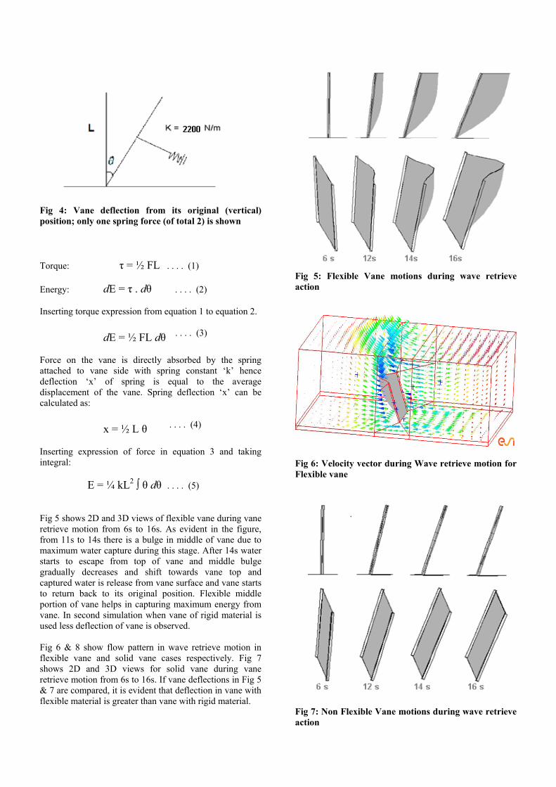
Fig 4: Vane deflection from its original (vertical) position; only one spring force (of total 2) is shown Torque: τ = ½ FL . . . . (1) Energy: dE = τ . dθ . . . . (2) Inserting torque expression from equation 1 to equation 2. dE = ½ FL dθ . . . . (3)
Force on the vane is directly absorbed by the spring attached to vane side with spring constant ‘k’ hence deflection ‘x’ of spring is equal to the average displacement of the vane. Spring deflection ‘x’ can be calculated as: x = ½ L θ . . . . (4)
Inserting expression of force in equation 3 and taking integral: E = ¼ kL2 ∫ θ dθ . . . . (5) Fig 5 shows 2D and 3D views of flexible vane during vane retrieve motion from 6s to 16s. As evident in the figure, from 11s to 14s there is a bulge in middle of vane due to maximum water capture during this stage. After 14s water starts to escape from top of vane and middle bulge gradually decreases and shift towards vane top and captured water is release from vane surface and vane starts to return back to its original position. Flexible middle portion of vane helps in capturing maximum energy from vane. In second simulation when vane of rigid material is used less deflection of vane is observed. Fig 6 & 8 show flow pattern in wave retrieve motion in flexible vane and solid vane cases respectively. Fig 7 shows 2D and 3D views for solid vane during vane retrieve motion from 6s to 16s. If vane deflections in Fig 5 & 7 are compared, it is evident that deflection in vane with flexible material is greater than vane with rigid material.
Fig 5: Flexible Vane motions during wave retrieve action
Fig 6: Velocity vector during Wave retrieve motion for Flexible vane
Fig 7: Non Flexible Vane motions during wave retrieve action

Fig 8: Velocity vector during Wave retrieve motion for Solid vane Equation 5 above gives energy absorbed by spring due to forward or backward motion of vane due to wave motion. Fig 9 shows comparison of total energy calculated from Equation 5 at various time intervals. It is evident from the graph that at every time interval energy captured from vane with flexible material is always greater than the energy extracted from vane of rigid material. Fig 10 shows forward and backward angles of both vanes from their vertical positions during various time intervals. Forward angles are given with positive sign whereas backward angles are given with negative sign. CONCLUSIONS Water flow across vanes of different materials is investigated numerically for a three dimensional system. Vanes of flexible and rigid materials are used to see the flow pattern and amount of energy captured. Amount of energy extractable from vane plate hinged from bottom and placed inside the seawater is dependent on the shape of that vane for similar wave conditions. Use of a vane with flexible material can extract more energy as it captures more water in its bucket shape during wave motion, and is subjected to stronger forces.
0
20
40
60
80
100
120
140
160
0 5 10 15 20 25
Time [s]
Acc
um
ula
ted
En
erg
y [J
]
Rigid Vane
Flexible Vane
Fig 9: Total Energy comparison
-12
-10
-8
-6
-4
-2
0
2
4
6
0s 2s 8s 9s 11s 16.5s 22s 25s
Time
Ang
le fr
om V
erti
cal P
osit
ion
(Deg
rees
)
Rigid-Vane Angle from Vertical Position
Flexible-Vane Angle from Vertical Position
Fig 10: Forward and Backward angles of Vanes from Vertical position REFERENCES
1- European renewable energy council (EREC), 2010, Renewable Energy in Europe Markets, Trends and Technologies -- Second Edition, Eartscan.
2- Da Rosa, A.,D., 2009, Fundamentals of Renewable Energy Processes -- second edition, Academic Press.
3- Andrews, J., Jelly, N., 2007, Energy Science Principles, technologies, and impacts, Oxford University Press.
4- Armstrong, F., Blundell, K., 2007, Energy Beyond Oil, Oxford University.
5- Mccrea, A., 2008, Renewable Energy; A user’s Guide , The Crowood Press Ltd.
6- Agamloh, E,.B, Wallace, A., K., Jouanne, A., V., 2008, Application of fluid–structure interaction simulation of an ocean wave energy extraction device, Renewable Energy, 33, pp. 748–757.
7- Chien, K.-Y., 1982, Predictions of Channel and Boundary-Layer Flows with a Low-Reynolds-Number Turbulence Model, AIAA Journal, 20, pp. 33-38.