Embed Size (px)
Citation preview

Florida Institute of Technology
Department of Marine and Environmental Systems
2008
Marine Diving Unit M.D.U. David Farris Taylor Paul Ryan Gielow Justin Gordon Colin Meigs

- 1 -
Table of Contents
Table of Contents ................................................................................................................... - 1 -
Purpose Statement ................................................................................................................ - 3 -
Objectives .............................................................................................................................. - 4 -
History ................................................................................................................................... - 5 -
Human Powered Submarine Races ..................................................................................... - 5 -
Submarine Evolution .......................................................................................................... - 6 -
Hydrogen Powered Submarines .......................................................................................... - 7 -
Hull Design and Modifications .............................................................................................. - 11 -
Hydrogen Fuel Cell ............................................................................................................... - 18 -
A Brief History on Hydrogen Fuel Cells ........................................................................... - 18 -
The MDU Ballard Hydrogen Fuel Cell ............................................................................. - 18 -
Fuel Cell Tests ................................................................................................................. - 22 -
Pressure Chamber ................................................................................................................ - 25 -
Design .............................................................................................................................. - 25 -
Construction ..................................................................................................................... - 29 -
Testing ............................................................................................................................. - 42 -
Buoyancy ............................................................................................................................. - 45 -
Steering................................................................................................................................ - 49 -
Initial Design and Planning .............................................................................................. - 49 -
Fabrication and Build ....................................................................................................... - 51 -
Potential Problems ........................................................................................................... - 58 -
Future Suggestions ........................................................................................................... - 59 -
Dive Planes........................................................................................................................... - 60 -
Twin Propulsion with Rear Power Thruster .......................................................................... - 63 -
Propulsion Tests ............................................................................................................... - 65 -
Variable Speed Control .................................................................................................... - 66 -
Waterproofing .................................................................................................................. - 67 -
Transportation and Deployment System .............................................................................. - 71 -
Possible Testing Sites ........................................................................................................... - 73 -
Testing Procedure ................................................................................................................ - 76 -
Long Term Goals .................................................................................................................. - 78 -
Finances ............................................................................................................................... - 79 -

- 2 -
Safety ................................................................................................................................... - 80 -
Machine Shop Work......................................................................................................... - 80 -
Scuba (FIT/PADI) ............................................................................................................ - 81 -
Marine Diving Unit Safety Components and Procedure .................................................... - 81 -
Table of Figures .................................................................................................................... - 85 -
Appendix A .................................................................................................................................. I
Appendix B ..................................................................................................................................II
Appendix C .................................................................................................................................III
Appendix D ............................................................................................................................... IV
Appendix E ................................................................................................................................ VI
References ............................................................................................................................... VII
Hours Worked ......................................................................................................................... VIII

- 3 -
Purpose Statement
The Purpose of senior design is to gain knowledge in the design, building, and testing
aspects of engineering. Our group will implement the skills we have learned throughout our
college careers and successfully complete a design project. The purpose of our project is to fit
the former human powered submarine (The U-Manatee) with a hydrogen fuel cell that will
power three 12 Volt electric trolling motors.
Figure 1 : Human Powered U-Manatee

- 4 -
Objectives
Before the fuel cell is placed in the MDU a series of tests are going to have to be made
to ensure that the fuel cell will work under the required pressures that will be applied while
diving. The fuel cell will be placed in a cylindrical pressure housing that will have an air pump to
ensure that the fuel cell will not be under any pressures that it cannot take. If for any reason
the fuel cell will not be able to be put in the MDU, 12 Volt batteries will be placed in the
pressure housing in its stead. However, the design process will continue as planned to fit the
MDU with the hydrogen fuel cell. Our overall objectives and expectations for the MDU is a
completely operable hydrogen fuel cell powered single-person submarine capable of diving to
depths of up to twenty feet. The team is well aware of the challenges ahead and is willing to
face them head-on.
The steering and propulsion systems will have to be completely changed as well. The
exact mechanisms have not yet been worked out, but as of now, the MDU group has decided
on a simple pulley system to turn the rear-mounted motors side to side much like an outboard
motor is turned. As mentioned above, two 12 Volt trolling motors will be used to propel the
submarine. Like the steering mechanisms, the exact means of mounting the motors has not yet
been decided, but the MDU team knows that modifications to the motors will have to be made
in order to mount them to the MDU. As of now, the team is looking at mounting the two
motors on a piece of metal or PVC pipe that will stick the motors out the sides of the stern of
the submarine.
To solve the problems of vertical movement and buoyancy, the team has decided to use
lift bags mounted on the outside of the MDU for surfacing. These lift bags are there for both
routine and emergency use. If anything should happen to the submarine that would cause it to
sink to the bottom, we will simply dive down and deploy the bags to surface the MDU. For
vertical steering, the team plans on refurbishing two dive planes that will be mounted on either
side of the forward section of the submarine.

- 5 -
History
Human Powered Submarine Races
The International Submarine Race was first started in 1989 in Riveria Beach, Florida. The
rules state that each team is to develop a one or two-person “Wet” submarine that will be
judged in many different categories. The goal of this competition is to inspire students of
different engineering backgrounds to come together and translate theoretical knowledge into
reality, while also advancing underwater vehicle propulsion, life support, and hydrodynamics.
The Florida Tech sub Sea Panther competed in the inaugural race and placed third out of
the 17 entries. For a period of time the sub was on display at the Ft. Lauderdale Museum of
Science and Discovery. The following race in 1991 grew in size with 35 boats participating. In
1993 the competition was held off Fort Lauderdale, Florida and the numbers continued to rise
with 44 boats. Florida Techs SEAFIT team received three awards, fourth place for cost
effectiveness and first for “Best Use of Submarine Maneuvering and Racing Tactics”. They also
won a cash prize of two thousand dollars and a plaque for “Most Effective Launch and Recovery
System”. Up until the 4th annual race in 1995, the competitions were held outside in open
water. This 1995 event marked the first International Submarine Race held indoors at the Naval
Surface Warfare Centers’ David Taylor Modeling Basin. The modeling basin building is 3200 feet
long and contains three independent towing test sites: a shallow water basin, a deep-water
basin, and a high speed basin. The facility is among the largest and best in the world for testing
sea-keeping qualities and propulsion of models.

- 6 -
Figure 2 : David Taylor Modeling Basin in Bethesda, Maryland
The first indoor race only drew 11 entries, but the second in 1997 inspired 16 teams to
participate. According to a newsletter sent out in 1999 the race was cancelled because the
modeling basin and race personnel were unavailable. The event was rescheduled for the year
2000 but actually took place in 2001. Florida Tech entered the U-Manatee into the 2001 race
and held first and second place during the first few days of competition. However, problems
with the propulsion shaft and gearbox caused them to drop back to fourth place behind
University of Michigan, Texas A&M, and University of British Columbia. New and innovative sub
designs continued in the 2003 races and in 2005 judges added a side-by-side race along with a
slalom course to judge maneuverability. The current speed record of 8.03 knots was set in 2007
by the University of Quebec’s’ OMER 5. The next competition is set to begin June 22, 2009.
Submarine Evolution
Leonardo da Vinci was the first to come up with the idea for a submarine and in 1578
William Bourne, a British mathematician, drew up the first engineering plans. His plans showed
water tanks that could be filled in order to descend and emptied to surface. Current day
submarines still employ this simple buoyancy principle for vertical navigation. The first
functioning submarine was built and developed by a Dutch inventor named Cornelius Drebbel.
It resembled an enclosed rowboat wrapped in leather with twelve oar slots extruding from its
sides. The vessel is said to have dove to a depth of about fifteen feet in the Thames River

- 7 -
containing twelve rowers and a few passengers. Oxygen was supplied to the vessel by surface
tubes connected to floats. There is speculation on whether vertical navigation was controlled
by rowing momentum or ballast tanks.
In 1776 the first war submarine “Turtle” was built by David Bushnell. It was designed to
stealthily travel up to a warship and drill into the hull and attach explosives. It was a simple
design using a small foot-operated valve to pump water weight in to sink and two propellers
used for vertical and forward movement. When the craft was put into use it failed drilling into
the ship and eventually bobbed up to the surface where it was spotted by the enemy and
promptly fired upon. Around 1797 Robert Fulton introduced several new things to submarine
design with his creation “Nautilus”. It was the first to incorporate dive planes for dynamic
navigation and a sail for surface propulsion. As time progressed into the 1800’s more people
started constructing submarines and therefore technology in the field advanced. During the
Civil War several submarines were built for both sides. “Hunley” was the first successful attack
submarine created by the Confederates; it sank a ship by ramming it with a large pole and
exploding a bomb attached to the end. In the late 1880’s battery-powered boats started to be
developed and the age of human powered underwater craft started to fade away. These boats
were very limited in their use and were quickly passed up for steam-power and eventually
diesel/gasoline engines. Around 1900 John Holland’s’ “Holland VI” became the first United
States Navy submarine. Surface propulsion was powered by a gasoline engine and when
submerged an electric engine kicked in. As submarine technology started to become more
reliable and deadly, many other countries added them to their navies as well. One of the most
famous and recognizable war subs around this time was the German U-1, or the “U-Boat”.
During this era some countries experimented with design changes such as miniature sizes and
airplane attachments. Diesel engines were the most common powerhouse until modern day
nuclear power.
Hydrogen Powered Submarines
Several countries along with the United States are developing hydrogen-powered
submarines. Canada, Germany, Russia, and United Kingdom are a few that have been
developing prototype programs. The Howaldtswerke-Deutsche Werft (HDW) Company
- 8 -
produced the first fuel cell propelled system in 2003 call the U 31 type 212A. It was developed
for the German Navy and in April of 2006 set a record for longest submerged trip for a non-
nuclear submarine; its total trip took about 14 days. It features a diesel motor along with an air-
independent propulsion system that uses proton exchange membrane hydrogen fuel cells. The
two power sources make it possible for the boat to travel fast at the surface and slow and
stealthy while submerged. These innovations also give the boat an impressive dive time of
about three weeks, minimal exhaust heat, and an almost silent trace. The sub is about 184 feet
long and weighs about 1,830 tons submerged; the maximum surface speed is 12 knots and
submerged speed is 20 knots.
The Russian Rubin Design Bureau built a version of the diesel/hydrogen hybrid called the
677 Lada class submarine; this sub is mainly based off the successful project 877 and 636 Kilo-
class submarines. Russia is planning on exporting the 677 under the Amur-class designation, in
which oxygen-hydrogen fuel cells will be an available option to extend run time. The diesel-
electric system is set up as a self-contained unit that can be installed into the base model, and
the ship is designed so that it can be run entirely from a main control room. Other state of the
art features are a new antisonar hull coating and a simultaneous multi targeting system.
Figure 3 : Hydrogen Powered Submarine

- 9 -
Figure 4 : Initial Solid Design
Figure 5 : See Through Initial Design
- 10 -
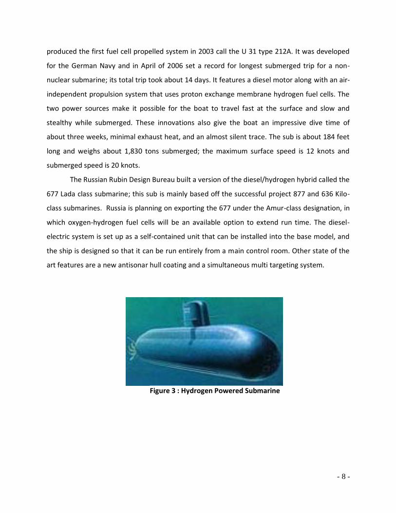
Figure 6 : Current Submarine Design

- 11 -
Hull Design and Modifications
The MDU team started working on the hull of the submarine in December of 2007. Our
first goal was to take out all of the old human powered devices. We also took initial
measurements so we would have a general idea of what we could work with. At this point it
was clear that our first part to modify would be the cockpit. The old human powered
submarine had two divers laying down so there was no need for an extended cockpit. Our new
version will have an extended hatch so the pilot will have maximum visibility. We have cut out
parts of the old submarine to which a plexiglas shield will be glued to.
The dive planes also needed a little bit of work as well. The area on the submarine
where the dive planes were attached had been torn down and instable. We decided to use the
same holes as the old U-Manatee but needed to build that area up for sufficient support of the
dive planes. We did this using structural marine grade putty. This would ensure structure
would have plenty of support for the kicking motion that the dive planes require.
Figure 7 : Dive Plane Repair
The back of the submarine required quite a bit of work as well. We first needed to fix
the back side hatch and the back hatch. We cut into the back hatch to make room for the two
side trolling motors. One of the problems we realized when we were cutting was that we
needed to cut normal to the xyz plane of the submarine. When we first took the hatch off we
started cutting normal to the hatch, which took away more material on the top than we
needed. These cuts we made also allow us to limit the amount of motion of the steering. This

- 12 -
back hatch is now held on with a hinge at the top and a clasp at the bottom to secure it from
moving when the submarine is in motion. This also allows for us to open it up very easily for
showcases and to work on.
The back side hatch was originally fiberglass and we wanted to make it a plexiglas piece.
We had old already curved piece of plexiglas from the old cockpit. This piece required sanding
and grinding out to make it fit the current hole we had. Once we got the plexiglas piece to fit
we attached a clasp and a hinge to it. When we had the paintjob done, we decided to go with
the old piece from the hull, because it still had the perfect fit. Instead of having a hinge and a
clasp, we are going to screw it in with the holes we already have. This will ensure it will not
move when the submarine is in motion.
Figure 8 : Back Side Hatch
Multiple mounts were needed inside the submarine to secure objects. We needed
mounts for our pressure chamber. We designed these mounts so the buoyancy force of the
pressure chamber is distributed over the submarine hull. If we had not done that we would
have 300lbs of force at a single point on the submarine. This would be a very high stress point
for the submarine. We also need to mount the steering system. The front pivot point is
through mounted with washers to ensure rotation is still easy. The back of the steering is also

- 13 -
through bolted to the bottom of the submarine. This is very important because it supports the
weight of two motors as well as the moment it takes to rotate the system. We also needed to
mount an extra support system for the rear T-bar because it would have a tendency to move
back and forth. We mounted the back main rear motor to a piece of aluminum using hose
clamps.
From the old U-Manatee, we had a cracked piece of curved plexiglas that had previously
been used for the nose cone. We decided the nose cone did not need to be see through for our
new design. We used calk to hold the entire piece together. Once it was secure, we applied
multiple layers of fiberglass over the surface. This fiberglass was very strong and would be
plenty of support in case the submarine was to crash into something. This nosecone required
quite a bit of sanding and putty to fill in gaps in the fiberglass. Once it was to the point where
we like it, we secured it to the submarine. We used a combination of Bondo and 4200. After it
was secured we sanded the surface smooth. This made it appear as part of the submarine.
Figure 9 : Finished Nosecone
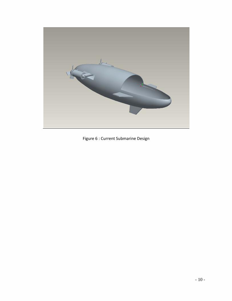
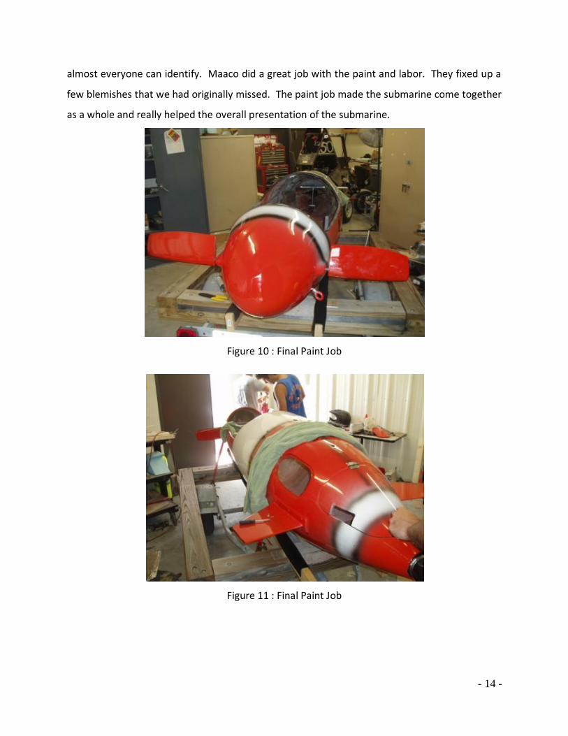
Once we had finished all the body work and touch ups we wanted we gave the
submarine to Maaco of Melbourne. Maaco donated all the labor and supplies for painting. As
a team we decided to go with the paint scheme of a clown fish. The orange and white colors
will both show up very well underwater as well as out of the water. A clown fish is a fish that
- 14 -
almost everyone can identify. Maaco did a great job with the paint and labor. They fixed up a
few blemishes that we had originally missed. The paint job made the submarine come together
as a whole and really helped the overall presentation of the submarine.
Figure 10 : Final Paint Job
Figure 11 : Final Paint Job

- 15 -
Cockpit Hatch Design
Our hydrogen fuel cell powered sub will be designed for one person. In order for this to
work the pilot must have sufficient visibility. This means we will have to change the current U-
Manatee submarine. The old U-Manatee had multiple windows, including one at the nose of
the submarine. Due to the fact that we are not lying down, we have created a new design that
will suit our intentions. We plan on installing a canopy that will resemble a fighter jet. It will be
elevated to the point where the pilot’s head will be able to see in 360:, and then come down to
reattach to the current hull. This reattachment will reduce drag and increase performance.
The easiest is to take the maroon piece from the old U-Manatee, and make cuts in that. This
way we will be able to fully remove the canopy. The ability to completely remove the canopy
will be useful when on display at design showcases, working on the sub, and in the case of an
emergency. When the sub is in use, we will attach the canopy using quick release latches
attached to the inside. These will minimize the time it takes to remove the canopy in case of
emergency.
Figure 12 : Pro Engineering Drawing of Cockpit Hatch
Once we figured out what we wanted to do we had to figure out how to do it. We could
either make the canopy out of flat sheets of plexiglas, or buy a large sheet, make a mold and
have a curved surface. The curved surface would reduce drag but it would also be harder and

- 16 -
more involved. We decided to keep it simple and go with the flat sheets of plexiglas instead of a
curved sheet.
Plastics Design & Mfg. Inc. and they said they would be willing to donate the labor for
creating the part to us. We used a high strength epoxy on the edges to make sure the structure
will be strong. We also use ¼’’ Plexiglas to maximize the visibility and reduce any distortion.
This design will fit the current cut we have made in the submarine.
Our main problem with this part was the design. The piece we are mounting it onto was
originally curved. We had to cut that so that the flat piece of Plexiglas would be attachable.
Once we figured out the dimensions of the piece we cut, we were able to find the parameters
of which the Plexiglas had to fit in. From here it was a simple drawing to create the current
design we have now.
Figure 13 : Finished Plexiglas Hatch
Once we received the cockpit hatch from Plastics Design & Mfg. Inc. we needed a way to
attach it to the submarine. Our initial plan was to take the piece we had and glue it to the
hatch so we would have extra support for the hatch. We then decided to put the piece we had
back on the submarine, and just make the plexiglas the movable piece. This required us to use
4200 to attach the piece on the submarine and then sand the surface smooth. We applied
multiple layers of Bondo, structural putty and marine grade putty to the surface and sanded it

- 17 -
down multiple times, each time filling in more and more of the cracks. Once this was smoothed
out, we applied a layer of weather stripping so the cockpit would be supported on a nice
moldable surface as opposed to the fiberglass.
The structural putty we received was a very high durable material. It had piece of
fiberglass which would increase the strength of the material. The fiberglass also made the
putty very hard to work with. We used the structural putty in the places we needed to build up
large amounts of surface to fill in gaps.
The marine grade putty we purchased from West Marine was very nice due to the fact it
was very easy to work with. We were able to mold the putty very easily and it led to us being
able to fill in almost any gap we needed. The downside of this putty was that it took a while to
kick. We used this putty when we would leave overnight and it would have a long time to cure.
Using the Bondo was very nice because like the marine grade putty, it was very easy to
mold, almost like a liquid. Another advantage to the Bondo was the curing time. On days
where we needed to apply four layers and sand them down we were able to because the Bondo
is able to be sanded within 20 minutes. The only down side of the Bondo was the strength. It
did not have a very high strength which meant for the most part, we used it to fill holes and
strictly for cosmetic purposes.
We also need the cockpit to be able to be removed from the inside as well as the
outside. We are going to drill into the submarine and wrap a bungee around two downward
facing hooks, one on each of the wall of the submarine. This has many advantages; one being it
is a very easy system to remove the hatch. If the pilot needs to evacuate the submarine, he will
just lift the interior bungees from the hooks and the hatch will be easily removed. If the diver
inside the submarine is unconscious, divers on the outside will be able to easily take off the
hatch using the same techniques. If one of the bungee cords happens to get wrapped, a diver
will be able to use a dive knife to cut the cord and get the diver out.

- 18 -
Hydrogen Fuel Cell
A Brief History on Hydrogen Fuel Cells
As early as 1838, a scientist named Christian Friedrich Schoenbein discovered that water
and an electric current can be created by combining hydrogen and oxygen gases. The first
hydrogen fuel cell, then called a “gas battery” was created in 1845 by Sir William Grove using
the theories of Christian Friedrich Schoenbein. While Grove did not invent the theories of the
potential of the fuel cell, he is still known as “The Father of the Fuel Cell.” German Scientists
have been using Hydrogen to power vehicles such as cars, trucks, busses, and even submarines
since the 1920’s. When hydrogen was first starting to be used in vehicles, it was mostly
conversion of combustion engines to ignite the hydrogen to drive a piston up and down. This
technique is still widely used today and is the main means power for hydrogen powered cars
and trucks.
Figure 14 : Sir William Grove
The MDU Ballard Hydrogen Fuel Cell
The hydrogen fuel cell being implemented in Marine Diving Unit is a fully electric fuel
cell utilizing hydrogen and oxygen from air. A few years back, a group of Mechanical Engineers
at Florida Institute of Technology put together a hydrogen fuel powered robot built to perform
certain tasks. The robot was no longer being used, so we were able to obtain the fuel cell from

- 19 -
the machine. The fuel cell puts out an average of 39 Volts of electricity, and since we are
powering three 12 Volt trolling motors, we need a Direct Current Power converters to step the
voltage from the fuel cell down to 12 Volts. We were able to obtain the two power converters
that we needed from the robot as well.
Figure 15 : Ballard Fuel Cell
As previously mentioned, the fuel cell is fully electric. This means that there is no
combustion needed to create power in the cell. This is different from the fuel cells that have
been typically used by automobile manufacturers because as of right now, the combustion fuel
cells are still much more efficient. The MDU fuel cell is basically a very powerful battery that
can produce its own power from hydrogen and oxygen from air. Pure oxygen cannot be used to
create the reaction in the cell. Only air must be used because if pure oxygen is used, the
reaction in the fuel cell is too rich and too much power is created, which basically “fries” the
cell. The hydrogen for the reaction is supplied by an external tank of gaseous hydrogen being
fed to the fuel cell by a hose controlled by a two phase regulator. The fuel cell gets its oxygen
from a fan that brings air into an intake port located on the top of the fuel cell. All excess or
unused air is blown out through channels on the top of the fuel cell. This air flow created by

- 20 -
the intake port and exhaust ports also acts as a cooling mechanism, much like the fans on a
computer or laptop.
Since the fuel cell is a “battery”, it needs an additional charge to be able to perform until
it is able to be self-sufficient. To start the fuel cell, it needs to be plugged into an external
power source to start the starter motor. The external power source comes from two “male”
plugs that plug into a power source that gets its power from a standard wall power outlet. The
starter motor is a small generator that contains a spinning turbine that creates a stored charge.
Once the cell has enough charge to run on its own power, the starter motor turns off. At this
point, the fuel cell may be unplugged from the external power source and will continue to run
off of the power it is creating from the hydrogen and oxygen. While the fuel cell is running with
the starter motor on, it sounds like a very small house-hold fan on a low setting because of the
spinning turbine in the generator. After the starter kicks off, the fuel cell runs almost silent.
Only the faint sound of the circulating air can be heard.
As mentioned above, the fuel cell gets its power from a reaction between hydrogen and
oxygen. The cell contains many rows of platinum metal sheets that surround rubber-like
membranes. These platinum sheets act as catalysts for the reaction to take place. Basically,
the platinum is an enabler. Hydrogen flows into the fuel cell from the external tank and the
oxygen needed for the reaction flows in from the intake port located on the top, right hand side
of the cell. The platinum sheets attract the two elements together to perform the reaction that
actually takes place in the membrane. When the hydrogen meets the oxygen, the proton from
the hydrogen is attracted to the oxygen. The remaining electron from the hydrogen is funneled
up the membrane into thin metal plates that lead into a wire bundle from which electricity will
be available. In actuality, the hydrogen being used is formula H2, both protons are taken from
the hydrogen molecule and added on to the oxygen molecule from the air. This reaction not
only funnels usable electricity to wires, but also creates water (H2 O) one molecule at a time.
These water molecules are also funneled out of the reaction chamber of the fuel cell into an
“exhaust” port that leads to a rubber hose. As previously mentioned, there is no combustion
need at all to create the power created by the fuel cell. With a non combustion, fully electric
fuel cell, there are no emissions. The only by-product is water. However, since the reaction is

- 21 -
only taking place one water molecule at a time, the amount of water produced is almost
negligible. For every ten minutes of run time of the cell, only one or two drops of water are
produced by the reaction.
Figure 16 : How A Fuel Cell Works
The fuel cell is a very finicky piece of machinery. For everything to work properly
(including the reaction, hydrogen and oxygen flows, and electricity flow) the surrounding
conditions must be close to perfect. As technology progresses, advancements have been made
to improve the performance and quality of hydrogen fuel cells. However, since the fuel cell
that is being implemented in the MDU was built seven years ago, we do not have all the
luxuries of the advancements in technology. The fuel cell will not run if the air being pulled in is
too salty, too wet, too warm, or two cold. If there is too much salt in the air, the fuel cell will
seize up and will not work until serviced. Also, after testing, we have found that the fuel cell is
also pressure sensitive and will not run in pressures greater than seven pounds per square inch.
This has created further problems than we anticipated, since we are designing the entire
submarine to withstand a maximum of twenty pounds per square inch. At this pressure the
fuel cell simply shuts off. However, this is not a major setback. The fuel cell will be sitting in a

- 22 -
pressure housing that will be designed to accommodate all the needs of the fuel cell. If for any
reason we will not be able to use the hydrogen fuel cell in the MDU, a series of 12 Volt batteries
will be used in its stead. Also, no design aspect will change regardless of what happens with the
fuel cell or what power source we use.
Fuel Cell Tests
Our first test with the fuel cell was to see if it would run under pressure. We made a
pressure chamber to test the fuel cell. In order to monitor the voltage across the terminals of
the fuel cell, we drilled two holes in a cap for wires and sealed them with epoxy. We connected
one end of the wires to a voltmeter and the other end in parallel with the load on the fuel cell.
We started running the fuel cell and sealed the pressure chamber. In order to increase the
pressure inside the chamber we ran air from an exterior compressor into the chamber. Until 7
psi the fuel cell was gradually increasing in voltage from 37 volts to 39 volts meaning the fuel
cell was running more efficient under pressure. We then watched a spike in the fuel cell
voltage and a steady drop to zero. When we drained the pressure and opened the chamber,
the fuel cell was not running. We gave the fuel cell 20 minutes to cool down and tried to run it
again. When we tried to run it again it did not turn on.
Figure 17 : Pressure Testing Apparatus

- 23 -
Multiple emails and phone conversations then took place with workers at Ballard and
Heliocentris. A faulty starting motor and broken membrane were our first ideas of what had
happened. After acquiring software to trouble shoot the fuel cell we hooked up the fuel cell to
a laptop. The cell had shut down because of a nonrestartable fault due to lack of oxygen. This
meant the circuit board on the fuel cell had self shut it down. This was one of the best case
scenarios because it was an easy fix. Once plugged into the computer software, we had to
reset the monitoring system on the fuel cell and it turned right on. This test also showed us we
need to supply a substantial amount of oxygen to the fuel cell in order for continuous run time.
Our next test was to hook the fuel cell to the motors and run the motors from the cell.
The fuel cell electricity had to be stepped down to 12 volts to match the trolling motor input.
There is also a relay switch that will keep the circuit open until the cell is out of its start up
phase. The relay is hooked in series with the DC to DC converter and then ran back into the fuel
cell. We have two outputs from the DC to DC converter that are then connected to the motors.
After connecting all of these components we turned on the fuel cell. We started the motors in
all five speeds forward. We then kicked the motors into reverse and they ran in the two
reverse speeds as well. This was a very good sign because it meant we could actually run our
three motors from the fuel cell.
Figure 18: Connecting the Fuel Cell to the Motors

- 24 -
Our next test is going to be a dry run of the fuel cell connected to the motors. We need
to set the pressure chamber inside the submarine with the fuel cell in it and have a test run of
the system. This will require the exhaust from the pressure chamber as well as the air inputs.
Once we run this test successfully, we will be ready to put the submarine under water and test
speed and maneuverability.

- 25 -
Pressure Chamber
Design
The pressure chamber that houses the fuel cell was one of the major design challenges
for our design group. The pressure chamber must protect the Nexa fuel cell from the damaging
effects of salinity, humidity, extreme temperatures, and water pressure. Before we began
building we made a list of design considerations that included having the pressure chamber
capable of withstanding outside pressures over 15 pounds per square inch, being resistant to
impact, resistant to corrosion, inexpensive, and easily machined. It had to be at least 18 inches
high, 12 inches wide and 22 inches long. Not only does the pressure chamber act as protection
for a $20,000 piece of equipment, but it is also the largest source of buoyancy.
Our initial design was to use a custom made rectangular box made of Plexiglas. There
are multiple benefits of this design. First, Plexiglas is relatively inexpensive. This characteristic
would allow us to build and test a design and still leave us funds to repair or improve the
chamber after testing. Plexiglas is also easy to cut and mold. This characteristic would allow us
to easily cut large sheets into a variety of sizes to fit multiple design ideas. This would enable us
to easily cut ports through the chamber to allow air and hydrogen in, and exhaust water,
battery cables, and exhaust air out. We also liked the idea of a transparent chamber so that we
could visually monitor the fuel cell for power and possibly see potential hazards such as leaks
before they become detrimental.
The cons of this design outweighed the benefits. Although Plexiglas is easy to cut and is
transparent, it is also prone to cracking. This type of failure would be catastrophic under the
pressure conditions of only a few feet of depth. The rectangular shape also needed to be
scrapped because of strength considerations. A rectangular chamber has too many joints and
glued connections where water could easily force its way through as the pressure required to
make a rectangular shape fail is relatively low. We did consider the idea of reinforcing the
Plexiglas box with threaded metal rod. We decided to drop this idea as well because every hole
that we would have to drill through the Plexiglas would be another site of low strength and
potential failure.

- 26 -
We looked into multiple material types to build our pressure chamber. Plexiglas and
fiberglass are not strong enough to withstand the potential water pressure at depth. We also
looked at using aluminum, titanium, and steel. Aluminum would have been a good fit for the
pressure chamber as far as strength, durability, workability, and cost. However, the density of
aluminum is 169 lb/ft^3 which would not offset the buoyant force of the displaced water from
the pressure chamber as well as a more dense metal. Titanium was also not dense enough as
well being too expensive to use. An acrylic pressure chamber would have been excellent at
protecting the fuel cell from pressure. However, acrylics are less workable than most common
metals and cannot be welded. A custom acrylic pressure chamber would also be very expensive
and less resistant to impact due to its lack of ductility. It would have very good corrosion
resistant properties.
We decided to build a cylindrical steel pressure chamber. We chose to use steel for
multiple reasons. Steel is easy to machine, making it easy to cut and add check valves and
pressure fittings to our tank as needed without greatly reducing the integrity of the structure.
Steel is also easy to weld. This characteristic ensured a strong sealing surface. We knew we
would be able to weld a secure and uniform steel flange around each half of the chamber that
will be able to be drawn together using through bolts. Being able to weld our chamber will
enable securely fastened through-chamber ports for fuel and exhaust as discussed earlier.
Figure 19 : Initial ProE Drawing of Pressure Chamber
Another perk of steel is its strength and ductile nature. If we do end up having an impact
either with the sea floor or perhaps an unexpected bump on the road while the sub is being
transported, it is more likely that the pressure chamber will bend and deform rather than crack

- 27 -
or chip and become useless. These dents and creases will be much less susceptible to the
pressure of depth than a crack and could ultimately prevent complete failure of the pressure
chamber.
We chose to use a cylindrical tank for multiple reasons. First, the shape of the cylinder is
much stronger than a rectangular shape yet it still provides protection for enough volume for
the fuel cell. While a rectangular chamber would be susceptible to pressure at every corner and
joint of material, the cylinder has no major joints of which stress would destroy. The cylindrical
shape will actually help to seal the chamber at depth. The even seal and pressure differential
between the operating pressure of the fuel cell and the hydrostatic pressure of the water depth
will force the two main pieces of the fuel cell together. This pressure differential will create
immense even pressure around the outside of the tank which will not be balanced by the inside
pressure, creating an extremely strong seal.
Figure 20 : Face of Pressure Chamber
The pressure operating conditions of the fuel cell created another problematic set of
conditions for the pressure chamber. Our first test of the fuel cell in the test pressure chamber
concluded with the result that the pressure chamber will not run when its surrounding gauge
pressure is over 7 psi. This creates two distinct problems. The first problem is that the fuel cell
must be kept between 7 psi and atmospheric pressure, meaning that a pressure regulation
system would need to be installed in the pressure chamber. An air pump would allow the
exhaust air to be removed to allow fresh air to be pumped through the fuel cell’s membrane.

- 28 -
This pump would also prevent pressure from building up in the tank and breaking the fuel cell
as it did in the first pressure test.
The 2nd problem is also related to the fact that the fuel cell runs best at atmospheric
pressure, meaning that the pressure on the outside of the pressure chamber will be greater
than the inside pressure once the chamber drops below the water surface. We considered if
this pressure differential may result in a need to re-enforce and strengthen the pressure
chamber. What strengthening needs to be done cannot be calculated until the pressure
chamber has been tested. In the future if greater depths want to be reached with the
submarine structural reinforcement could be added as an exoskeleton or reinforcing frame for
the pressure chamber.
In order to mathematically calculate the strength of the cylindrical tank with spherical
ends we calculated the maximum stress capable of being resisted by a solid cylindrical sphere
with no seal or through ports. The first thing we did was to calculate the pressure at 10m (30ft)
Pressure = ρgh
P = (1000 kg/m3) (9.81 m/s2) (10 m)
P = 98,100 Pa = 98.1 kN/m2= 142 psi
Next we needed to find the failure stress for steel. This value was taken from lecture
notes from Dr. Wood’s Offshore Engineering class.
E for steel = 375 MN/m2
Lastly, we needed to calculate the actual stress capable of making the pressure chamber
fail. For the calculations the radius of the cylinder was 10” and the thickness of the cylinder
walls was 1/8”.
P (R/2t) < ςy
(98,100 Pa)(0.254m/(2*.003175m))
3,924,000 N/m2 < 375, 000,000 N/m2
569 psi < 543,750 psi
This calculation showed that if we used a solid cylindrical shell our tank would be almost
100 times over designed. This factor of safety will hopefully account for the large seal

- 29 -
connecting the 2 pieces of tank as well as the through ports which will all be increased areas of
stress. We will not know our greatest possible pressure ranges until the pressure chamber can
be tested under multiple circumstances.
One option we considered to handle the pressure requirements of the fuel cell was to
completely seal the pressure chamber off from any input of air or other gas. We could
theoretically start the fuel cell, and then lock it into the sealed chamber where the fuel cell
could run until it consumed the air inside the volume of the chamber or the oxygen in the air is
completely consumed. This would solve the problem of trying to power a pump. It would
however directly affect the amount of bottom time that the submarine is capable of diving for.
It would also reduce the cost of the overall pressure chamber as an exhaust port would not
have to be purchased or implemented in the design. We ended up scrapping this idea because
the fuel cell’s oxygen consumption rate (90 SLPM) was much too high to allow for an acceptable
bottom time.
Our final design for pressure control was to use a snorkel system to keep the tank
constantly at atmospheric pressure. By using a reinforced crush resistant hose, not only will the
pressure be constant but it will also provide an exhaust for deoxygenated air as well as serve to
dissipate heat.
As mentioned in the safety section, hydrogen is 2.4 times more explosive than gasoline. We
therefore needed to design our pressure chamber with safety in mind. In order to protect the
diver from an explosion we added a 2” diameter pressure relief valve to dissipate the explosive
energy and expanded volume of air through the bottom of the pressure chamber. This will
prevent the entire pressure chamber failing and possibly injuring the operator who sits only a
few inches away.
Construction
Our final design called for a 30 inch long cylinder with a 20 inch diameter. The tank has 1/8th
thick walls and will be constructed from an old air receiver. John Paul, a professional engineer
for Lake Champlain Transportation Company has donated a tank from which our pressure

- 30 -
chamber was built. He shipped a 50in long tank with a 20in diameter, in two 110 lb pieces from
his hometown in Vermont.
Figure 21 : Initial Condition of Air Receiver Tank
In order to design and build our connecting flange we needed to find a piece of steel
from which to make it. We contacted multiple industrial metal suppliers as well as the metal
suppliers for the Florida Tech machine shop. We could not find any companies willing to donate
or even discount the piece of steel we required. Bill Battin, a Florida Tech Technician was able
to locate a 3’ x 5’ x 3/8” piece of steel that we could use.
Figure 22 : Initial Condition of Steel Plate
Before we could begin work on the pressure chamber or flange we had to have both the
steel sheet and the steel air receiver tank sandblasted. Sandblasting removes old paint, rust, as
well as any biofouling or corrosion that has begun on the metal. After explaining our project
and a little begging, East Coast Sandblasting, in West Melbourne, FL, donated the labor to
sandblast both the tank and the sheet.

- 31 -
Figure 23 : Steel Materials after Sandblasting
Once our materials were sandblasted and clean we began the cutting process. We had to
cut out a section from the tank to shorten it to 30 in. Since the tank was shipped to us in two
pieces we had to cut a section off of each half. We made one section of the tank 20” and the
other side 10” long. This would make the longer section of the tank able to house most of the
fuel cell as well as more stable inside the submarine. In turn the smaller section of the tank
would be lighter and easier to lift in and out of the submarine as well as easier to hold while
being bolted in place. Bill Bailey in the Florida Tech machine shop was able to cut the tanks
using a standard cutting torch.
Figure 24 : Small Tank Section Ready for Cutting

- 32 -
Figure 25 : Large Tank Section Ready for Cutting
Figure 26 : Sections Removed by Cutting
Figure 27 : Machinist Bill Bailey Cuts Air Tank
The next thing we had to do was weld 2” steel flanges around the edges of the tanks making
sure that the edges are uniform and smooth. Our first desire was to use a CNC milling machine
to cut out the flanges as exactly as possible. However, the Florida Tech CNC does not have
enough travel to machine such large flanges. So we used a large compass to draw our flanges
out onto the steel plate. We drew two concentric circles one with a 20” diameter and the other

- 33 -
with a 24” diameter. This gave us a 2” wide flange that was uniform and even. We used the
same compass to mark the eight bolt holes through the flange. Bill Bailey was able to cut out
our flanges for us again using a standard cutting torch.
Figure 28 : Design for Flange
Figure 29 : Flange Ready for Cutting
Figure 30 : Machinist Bill Bailey Cuts Out Flange

- 34 -
Once the flanges were cut out they had to be grinded smooth to create an even sealing
surface. We used an electric grinder to remove all the welding splatter.
Figure 31 : Grinding Flanges Smooth
The flanges were cut by hand and were therefore not exactly identical. We tack welded the
two flanges together and used a drill press to drill the eight 3/8” holes where the bolts will draw
the flanges together. Because the holes were drilled by hand the flanges line up best in only
one position. This position had to be marked and noted for when the pressure chamber would
be bolted together.
Figure 32 : Drilling Through Bolt Holes in Flange
These two flanges became the surfaces between which a thick rubber gasket is used to
uniformly complete the seal. Each flange was drilled with 8 uniformly spaced holes. These holes
will be used to tighten the 2 pieces of the chamber together to create the tightest seal possible.
It is imperative that the bolts be tightened slowly and uniformly to create the strongest and
best seal. The number of tightening bolts that must be used is still under consideration as well
as the size of the rubber gasket to be used in the seal.

- 35 -
Once the flanges were ready we placed them onto the tank edges to be welded. The tank
halves had lost some of their shape since being cut for so long making the welding process
difficult. We had to use clamps, vice grips and levels to make sure that the flanges were welded
on squarely and properly.
Figure 33 : Machinist Bill Bailey Welding Flange onto Pressure Chamber
Once the flanges were welded onto the tank halves we again needed to grind all the
surfaces smooth. This is important because any rough edges could not only be dangerous to the
people handling the pressure chamber but hey could also be potentially harmful to any wiring
or other electrical equipment that is being housed in the pressure chamber. Most importantly
the mating surfaces need to be as smooth as possible to create a water tight seal.
Figure 34 : Grinding Welding Residue
Once the flanges were welded into place it was time to design the mounting system for the
interior of the pressure chamber. The pressure chamber had to house the fuel cell, a DC-DC
converter, a relay switch that protects the fuel cell, and the hydrogen supply tank. The first

- 36 -
thing we did was to design the feet for the fuel cell. We used the ban saw to cut 2” steel square
stock into four uniformly sized feet. Next we had to drill and tap each of the feet so that the
rubber base feet for the fuel cell could be threaded securely into the feet. Once this was done
we built a template out of plywood. The template allowed the feet to be welded into the
chamber while being properly spaced and square to each other.
Figure 35 : Template for Fuel Cell Mounting System
Figure 36 : Fuel Cell Mounting Feet
Figure 37 : Fuel Cell Mounted in Pressure Chamber

- 37 -
The next step was to mount the DC-DC converter. We used a piece of L-bracket to machine
the feet for the converter. We used an aluminum template so that Bill Bailey could weld the
feet in squarely and properly spaced.
Figure 38 : Mounting System for DC to DC Converter
Figure 39 : DC to DC Converter Mounted in Chamber
The converter feet were welded to the top of the tank so that the converter hangs over the
top of the fuel cell. We did this to conserve space inside the pressure chamber. The fuel cell and
converter both fit very well into the mounts and we were very happy with the security that the
bolted mounts provided us with the expensive equipment.
- 38 -
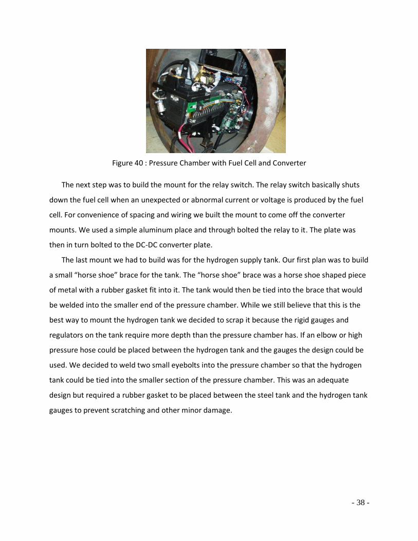
Figure 40 : Pressure Chamber with Fuel Cell and Converter
The next step was to build the mount for the relay switch. The relay switch basically shuts
down the fuel cell when an unexpected or abnormal current or voltage is produced by the fuel
cell. For convenience of spacing and wiring we built the mount to come off the converter
mounts. We used a simple aluminum place and through bolted the relay to it. The plate was
then in turn bolted to the DC-DC converter plate.
The last mount we had to build was for the hydrogen supply tank. Our first plan was to build
a small “horse shoe” brace for the tank. The “horse shoe” brace was a horse shoe shaped piece
of metal with a rubber gasket fit into it. The tank would then be tied into the brace that would
be welded into the smaller end of the pressure chamber. While we still believe that this is the
best way to mount the hydrogen tank we decided to scrap it because the rigid gauges and
regulators on the tank require more depth than the pressure chamber has. If an elbow or high
pressure hose could be placed between the hydrogen tank and the gauges the design could be
used. We decided to weld two small eyebolts into the pressure chamber so that the hydrogen
tank could be tied into the smaller section of the pressure chamber. This was an adequate
design but required a rubber gasket to be placed between the steel tank and the hydrogen tank
gauges to prevent scratching and other minor damage.

- 39 -
Figure 41 : Hydrogen Tank in Chamber
Figure 42 : Horseshoe Mounting System
Once the interior mounting systems had been built and designed we painted the outside of
the pressure chamber. We painted the pressure chamber with an industrial corrosion and rust
inhibitor. We used standard Rustoleum spray paint. We chose to use white for its high visibility
and its matching color scheme to the body of the submarine.
- 40 -
Figure 43 : Painting the Pressure Chamber
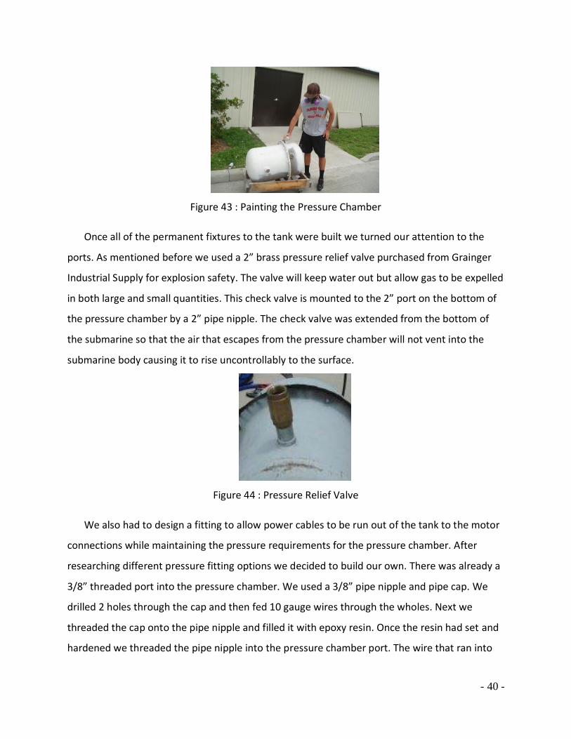
Once all of the permanent fixtures to the tank were built we turned our attention to the
ports. As mentioned before we used a 2” brass pressure relief valve purchased from Grainger
Industrial Supply for explosion safety. The valve will keep water out but allow gas to be expelled
in both large and small quantities. This check valve is mounted to the 2” port on the bottom of
the pressure chamber by a 2” pipe nipple. The check valve was extended from the bottom of
the submarine so that the air that escapes from the pressure chamber will not vent into the
submarine body causing it to rise uncontrollably to the surface.
Figure 44 : Pressure Relief Valve
We also had to design a fitting to allow power cables to be run out of the tank to the motor
connections while maintaining the pressure requirements for the pressure chamber. After
researching different pressure fitting options we decided to build our own. There was already a
3/8” threaded port into the pressure chamber. We used a 3/8” pipe nipple and pipe cap. We
drilled 2 holes through the cap and then fed 10 gauge wires through the wholes. Next we
threaded the cap onto the pipe nipple and filled it with epoxy resin. Once the resin had set and
hardened we threaded the pipe nipple into the pressure chamber port. The wire that ran into

- 41 -
the pressure chamber was connected to the DC-DC converter and the wire that ran outside the
cap was connected to the motor circuit. This fitting design proved to be both effective and
inexpensive.
Figure 45 : Power Output Wire Port
We chose to solve the pressure issue by using a snorkel system. We decided to run two 50’
snorkels from the tank. One snorkel is specifically for pressure equalizing. This hose keeps the
pressure chamber consistently at atmospheric pressure. The second snorkel is used for venting
the water vapor and heat exhaust from the fuel cell. The fuel cell exhaust will be attached to a
water separator which will then be run into the snorkel. The snorkels are attached to the
pressure chamber by threaded brass barb fittings. Kuriyama of America, Inc donated 100 feet of
1” diameter rigid white PVC helix enforced hose to use as our snorkel system. This reinforced
hose is a good fit for a snorkel system because it is crush resistant and won’t be collapsed by
the water pressure. The hose will begin to collapse around 16 psi which is around 35 feet. The
submarine is currently designed to dive between 15 and 20 feet so this should be adequate.
Figure 46 : PVC Helix Reinforced Tubing
The fuel cell needs a steady supply of 20% oxygen air to run efficiently. We found that the
fuel cell would use the oxygen in a sealed tank relatively quickly as mentioned in the fuel cell
testing section. To solve this problem we designed a regulated air input system from a standard
scuba cylinder. We connected a quick connect BC hose that we bought from Hatt's Diving to a
- 42 -
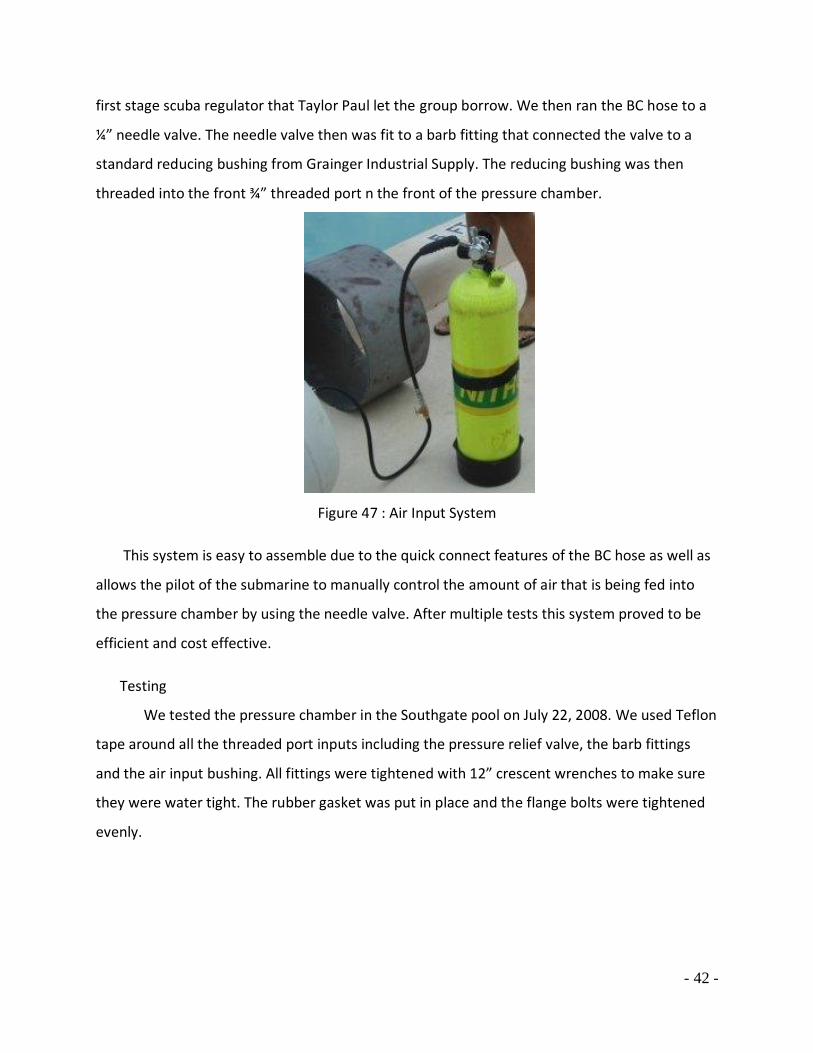
first stage scuba regulator that Taylor Paul let the group borrow. We then ran the BC hose to a
¼” needle valve. The needle valve then was fit to a barb fitting that connected the valve to a
standard reducing bushing from Grainger Industrial Supply. The reducing bushing was then
threaded into the front ¾” threaded port n the front of the pressure chamber.
Figure 47 : Air Input System
This system is easy to assemble due to the quick connect features of the BC hose as well as
allows the pilot of the submarine to manually control the amount of air that is being fed into
the pressure chamber by using the needle valve. After multiple tests this system proved to be
efficient and cost effective.
Testing
We tested the pressure chamber in the Southgate pool on July 22, 2008. We used Teflon
tape around all the threaded port inputs including the pressure relief valve, the barb fittings
and the air input bushing. All fittings were tightened with 12” crescent wrenches to make sure
they were water tight. The rubber gasket was put in place and the flange bolts were tightened
evenly.
- 43 -
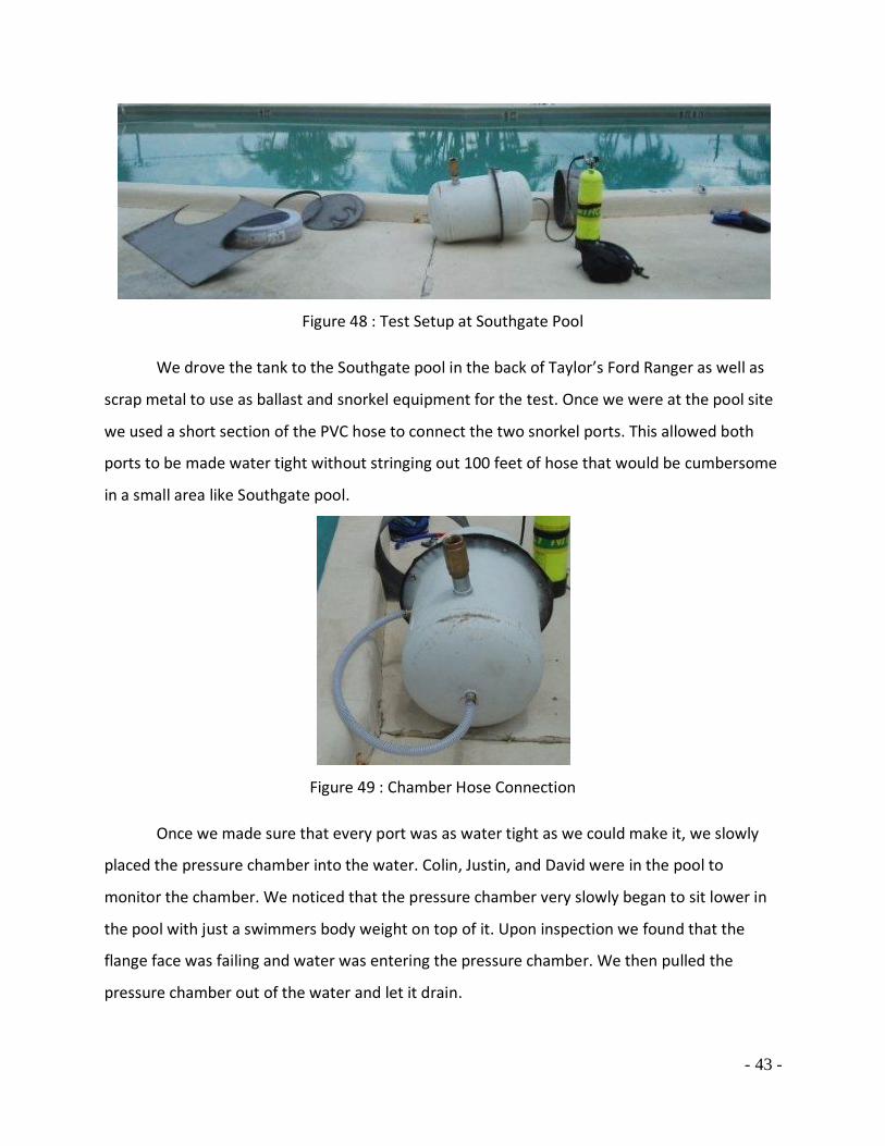
Figure 48 : Test Setup at Southgate Pool
We drove the tank to the Southgate pool in the back of Taylor’s Ford Ranger as well as
scrap metal to use as ballast and snorkel equipment for the test. Once we were at the pool site
we used a short section of the PVC hose to connect the two snorkel ports. This allowed both
ports to be made water tight without stringing out 100 feet of hose that would be cumbersome
in a small area like Southgate pool.
Figure 49 : Chamber Hose Connection
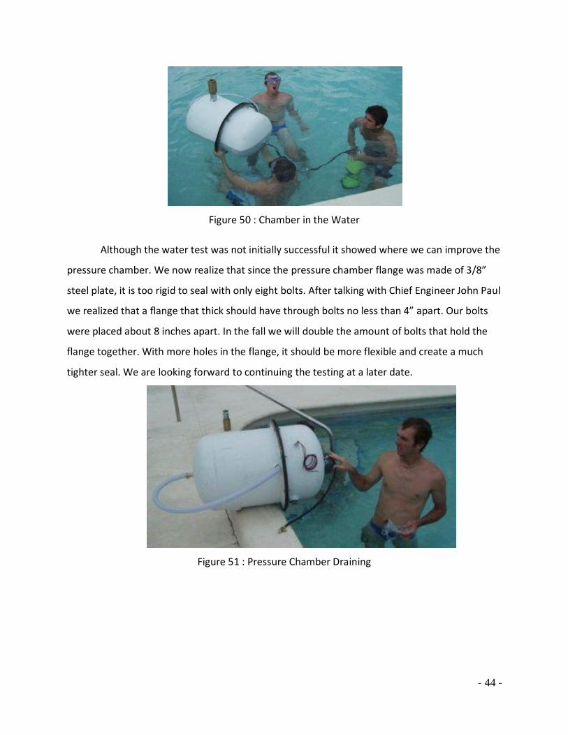
Once we made sure that every port was as water tight as we could make it, we slowly
placed the pressure chamber into the water. Colin, Justin, and David were in the pool to
monitor the chamber. We noticed that the pressure chamber very slowly began to sit lower in
the pool with just a swimmers body weight on top of it. Upon inspection we found that the
flange face was failing and water was entering the pressure chamber. We then pulled the
pressure chamber out of the water and let it drain.
- 44 -
Figure 50 : Chamber in the Water
Although the water test was not initially successful it showed where we can improve the
pressure chamber. We now realize that since the pressure chamber flange was made of 3/8”
steel plate, it is too rigid to seal with only eight bolts. After talking with Chief Engineer John Paul
we realized that a flange that thick should have through bolts no less than 4” apart. Our bolts
were placed about 8 inches apart. In the fall we will double the amount of bolts that hold the
flange together. With more holes in the flange, it should be more flexible and create a much
tighter seal. We are looking forward to continuing the testing at a later date.
Figure 51 : Pressure Chamber Draining

- 45 -
Buoyancy
As with the design of any underwater vehicle, buoyancy is an integral part of the design.
The buoyancy must be effective and reliable as rapid changes in depth can be very dangerous
for a diver. We explored multiple possibilities for the MDU’s buoyancy control.
One consideration of using a large pressure chamber is the amount of water that it
displaced. The more water the chamber displaces, the more buoyant it is and the more ballast
weight will be needed to balance and control the buoyancy. We used the following calculation
to determine the buoyant force of the pressure chamber in design.
Force of Buoyancy = Weight - Weight of volume of Water Displaced
Tank Buoyancy = 200 lb – πr2h (64.2 lb/ft3)
Tank Buoyancy = 200 lb – π (.823ft) 2(30in/12 in/ft) (64.2 lb/ft3)
Tank Buoyancy = 341 lb
We decided to use this 340 lb of buoyant force to be our main source of buoyancy for the
submarine. Our next challenge then became how to make the submarine become neutrally or
negatively buoyant. We looked into many different sources of ballast. We considered and
compared different materials.
Density of Possible Ballast Materials
Material Density (lb/ft3)
Iron 491
Lead 709
Aluminum 169
Steel 490
After talking with multiple engineers we have decided that iron (density = 491 lb/ ft3) and
lead (density = 709 lb/ ft3) are our two most efficient materials to be used as ballast. Both
materials are relatively inexpensive as scrap, dense, and stable. There are multiple sources of
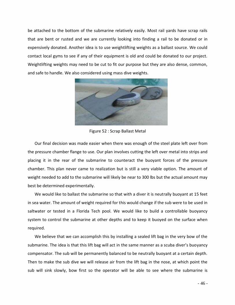
where we could acquire this scrap metal. The iron rails weigh over 300 lbs per yard and could
- 46 -
be attached to the bottom of the submarine relatively easily. Most rail yards have scrap rails
that are bent or rusted and we are currently looking into finding a rail to be donated or in
expensively donated. Another idea is to use weightlifting weights as a ballast source. We could
contact local gyms to see if any of their equipment is old and could be donated to our project.
Weightlifting weights may need to be cut to fit our purpose but they are also dense, common,
and safe to handle. We also considered using mass dive weights.
Figure 52 : Scrap Ballast Metal
Our final decision was made easier when there was enough of the steel plate left over from
the pressure chamber flange to use. Our plan involves cutting the left over metal into strips and
placing it in the rear of the submarine to counteract the buoyant forces of the pressure
chamber. This plan never came to realization but is still a very viable option. The amount of
weight needed to add to the submarine will likely be near to 300 lbs but the actual amount may
best be determined experimentally.
We would like to ballast the submarine so that with a diver it is neutrally buoyant at 15 feet
in sea water. The amount of weight required for this would change if the sub were to be used in
saltwater or tested in a Florida Tech pool. We would like to build a controllable buoyancy
system to control the submarine at other depths and to keep it buoyed on the surface when
required.
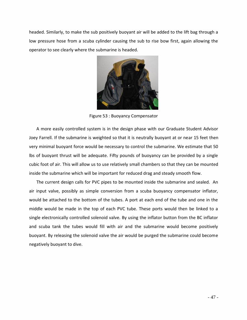
We believe that we can accomplish this by installing a sealed lift bag in the very bow of the
submarine. The idea is that this lift bag will act in the same manner as a scuba diver’s buoyancy
compensator. The sub will be permanently balanced to be neutrally buoyant at a certain depth.
Then to make the sub dive we will release air from the lift bag in the nose, at which point the
sub will sink slowly, bow first so the operator will be able to see where the submarine is
- 47 -
headed. Similarly, to make the sub positively buoyant air will be added to the lift bag through a
low pressure hose from a scuba cylinder causing the sub to rise bow first, again allowing the
operator to see clearly where the submarine is headed.
Figure 53 : Buoyancy Compensator
A more easily controlled system is in the design phase with our Graduate Student Advisor
Joey Farrell. If the submarine is weighted so that it is neutrally buoyant at or near 15 feet then
very minimal buoyant force would be necessary to control the submarine. We estimate that 50
lbs of buoyant thrust will be adequate. Fifty pounds of buoyancy can be provided by a single
cubic foot of air. This will allow us to use relatively small chambers so that they can be mounted
inside the submarine which will be important for reduced drag and steady smooth flow.
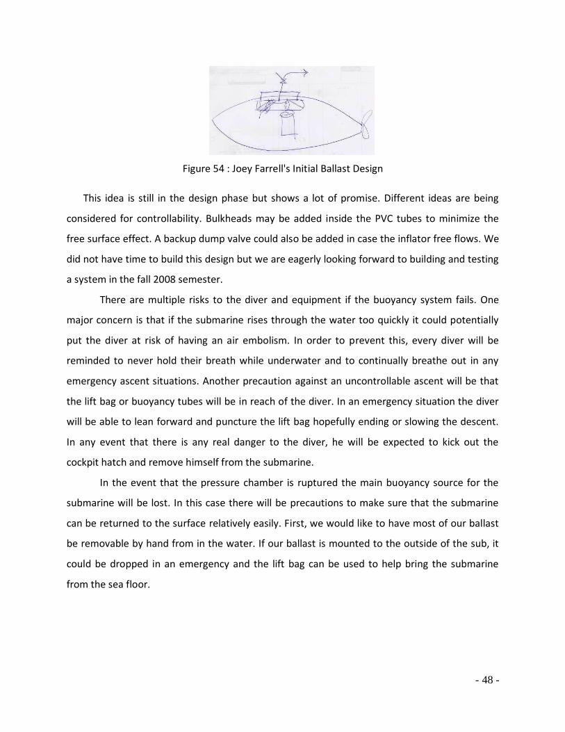
The current design calls for PVC pipes to be mounted inside the submarine and sealed. An
air input valve, possibly as simple conversion from a scuba buoyancy compensator inflator,
would be attached to the bottom of the tubes. A port at each end of the tube and one in the
middle would be made in the top of each PVC tube. These ports would then be linked to a
single electronically controlled solenoid valve. By using the inflator button from the BC inflator
and scuba tank the tubes would fill with air and the submarine would become positively
buoyant. By releasing the solenoid valve the air would be purged the submarine could become
negatively buoyant to dive.
- 48 -
Figure 54 : Joey Farrell's Initial Ballast Design
This idea is still in the design phase but shows a lot of promise. Different ideas are being
considered for controllability. Bulkheads may be added inside the PVC tubes to minimize the
free surface effect. A backup dump valve could also be added in case the inflator free flows. We
did not have time to build this design but we are eagerly looking forward to building and testing
a system in the fall 2008 semester.
There are multiple risks to the diver and equipment if the buoyancy system fails. One
major concern is that if the submarine rises through the water too quickly it could potentially
put the diver at risk of having an air embolism. In order to prevent this, every diver will be
reminded to never hold their breath while underwater and to continually breathe out in any
emergency ascent situations. Another precaution against an uncontrollable ascent will be that
the lift bag or buoyancy tubes will be in reach of the diver. In an emergency situation the diver
will be able to lean forward and puncture the lift bag hopefully ending or slowing the descent.
In any event that there is any real danger to the diver, he will be expected to kick out the
cockpit hatch and remove himself from the submarine.
In the event that the pressure chamber is ruptured the main buoyancy source for the
submarine will be lost. In this case there will be precautions to make sure that the submarine
can be returned to the surface relatively easily. First, we would like to have most of our ballast
be removable by hand from in the water. If our ballast is mounted to the outside of the sub, it
could be dropped in an emergency and the lift bag can be used to help bring the submarine
from the sea floor.

- 49 -
Steering
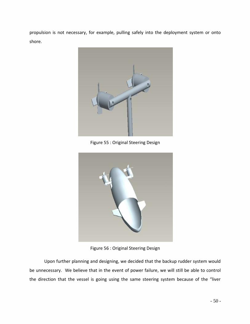
Initial Design and Planning The Marine Diving Unit has an advanced integrated steering system. In this system,
there are series innovative mechanical designs that incorporate steering control with
propulsion. Instead of ruder steering systems used in past human powered submarines, the
Marine Diving Unit utilizes thrust angles to change the sub’s heading. Most motorized water
craft use the same concept including everything from Jet Skis to recreational boats. The
orientation of the moving propellers produces the boats heading to change. When the
propeller faces toward the port side of the vessel, the vessel takes a starboard heading. This
design feature gives us the ability to change directions almost instantaneously. Quick lateral
steering capability is an essential piece to unproblematic piloting.
The initial design for the steering system was designed around a T-bar, which two
trolling motors are mounted. The trolling motors are attached to the T-bar with a weld, thus
giving us a water tight area to run electrical wires through. The T-bar is mounted to a swivel
point in the rear of the sub allowing it to rotate. The swivel mount, allows the trolling motors
to rotate on a single axis. Cutouts, in the rear of the sub, give the T-bar a free range of motion.
The steering is controlled through a series of pulleys, mounted in the cockpit of the sub. The
pulleys are mounted to handle bars well in reach of the pilot. The handle bars will have a
locking device which will allow us to keep a heading without worrying about motors moving on
their own. This pulley system gives the pilot an immediate uncomplicated method of
maneuvering.
Since our steering system relays entirely on angle thrust, we need a backup plan in case
the power system is to shutdown. Our design includes a backup ruder, which is the forward
section of the sub underneath the pilot, to allow steering when trust is not available. All
motorized water craft are practically useless when propulsion does not exist. This ruder will
give us maneuverability when propulsion is not necessary, for example, pulling safely into the
deployment system or onto shore. The ruder is removable because transportation will damage
it. It is mounted to handle bars between the pilot and to front of the vessel. Its location gives
the pilot immediate control when power is lost. This ruder will give us maneuverability when
- 50 -
propulsion is not necessary, for example, pulling safely into the deployment system or onto
shore.
Figure 55 : Original Steering Design
Figure 56 : Original Steering Design
Upon further planning and designing, we decided that the backup rudder system would
be unnecessary. We believe that in the event of power failure, we will still be able to control
the direction that the vessel is going using the same steering system because of the “liver

- 51 -
guards.” These protective rings around the motors should provide a good enough angle to
steer the vessel, even if it is only slightly.
While designing and planning out our T-bar steering system, we thought it would be
best that the motors not be welded onto the shafts of the T-bar. We came upon this decision
because we thought it would be a much better design to be able to remove the motors or
shafts from the assembly. To be able to accomplish this, we decided to use the stock threads
on the shaft for the motor attachment and have the other end of the shaft threaded for
attachment to the T-fitting.
Fabrication and Build The early fabrication process of the steering system started with the use of scaled down
cardboard pieces at a scale of 1:2. The cardboard was used to create a complete one half sized
replica of our proposed steering system. The first step was to create a triangular hinge piece
that would eventually attach to the cardboard shaft of the port side trolling motor using a nut,
bolt, and washer. Next we attached a strip of cardboard to the triangular hinge piece with a
small nut and bolt ensuring that there would be free rotation between the strip and the
triangular hinge when the strip of cardboard was pushed and pulled. We supported the
cardboard shaft in the center with a drill bit all the way trough so the shaft would be able to
rotate sided to side for testing. The shaft was prevented from sliding down the drill bit by
electrical tape that was wrapped multiple times around the bit.

- 52 -
Figure 57 : Materials Used For Steering Model
Figure 58 : Working Steering Model

- 53 -
In order for the two outside trolling motors to be able to rotate back and forth, we
assemble a T-bar system. The T-bar system includes the two trolling motor shafts connected to
a T fitting from the sides, a piece of aluminum rod (which was a piece of one of the motor
shafts that we cut off) coming out of the bottom of the T fitting, a sealed ball bearing for side to
side movement, an aluminum plate, and an aluminum wedge. The ball bearing was purchased
from Granger Tools and the aluminum used to make the wedge was scrap metal donated by Bill
Bailey. We had the shafts of the trolling motors threaded at the end opposite of the motor in
order to fasten them into the T fitting. After having the rods threaded, we ran the control wires
from the motors through the T fitting and down the vertical aluminum tube out the bottom.
The vertical aluminum tube was pressed through the sealed ball bearing, which was held in
place by being pressed into the quarter inch thick aluminum plate. In order to make sure that
the vertical piece of aluminum tubing was actually vertical, we needed to fabricate a wedge to
compensate for the upward angling stern of the vessel. To find the angle at which the bottom
slopes up, we started by using a piece of wood cut into a wedge that was one inch tall at the
top of the slope. We then attached three screws into the bottom of the wooden wedge and
the thickest part (one at either edge and one in the middle) along the back edge. Placing a level
on top of the wooden wedge we then screwed the screws in and out until the top of the wedge
was level. After making sure the wedge was level forward and backward, and side to side, we
measured out the height of the back and the overall length. Using these dimensions, we used
pieces of quarter inch thick aluminum plate to make the wedge. After the aluminum pieces
were machined out and assembled, we attached them to the bottom of the submarine using
through bolts through the bottom. On the outside of the submarine, we bent a thin piece of
aluminum sheet to match the curvature of the submarine that we drilled through and used to
help anchor the wedge to the bottom of the submarine. We did this to help the fiberglass hull
of the submarine support the weight of the assembly. The aluminum plate with the bearing
now in pressed in it was then attached to the aluminum wedge piece, reassuring that the T-bar
steering system sat level to the ground while being attached to the upward angling stern of the
submarine.

- 54 -
Now it was time to integrate the T-bar to controls that would be used by the pilot of the
vessel. To fabricate the design, we used all aluminum pieces to ensure that there would be
minimal corrosion on the members of the steering apparatus. We went to ACE Hardware to
obtain the necessary pieces for the steering system. We purchased two aluminum rods
measuring four feet each with a diameter of three eighths inches, two pieces of sheet
aluminum measuring four inches by nine inches, and aluminum nuts and bolts.
We started with the two, four foot long aluminum rods that we had welded together
by Bill Bailey. After having the rods welded together, we cut out the triangular hinge piece
from a sheet of aluminum that was donated to us by Bill Bailey as scrap aluminum. We cut out
the triangle piece by making a series of three cuts using a band saw. The triangular piece was
an equilateral triangle with sides measuring three inches with a thickness of one quarter inch.
We had this triangular piece welded to the port side trolling motor’s shaft with one of the
points/angles of the triangle facing inward towards the center of the submarine. After securing
the triangular piece we cut out a rectangular piece of aluminum from the thin aluminum sheet
purchased from ACE measuring three quarter inches by three inches. We had this piece welded
to one of the ends of the aluminum rod one and a half inches up the rectangular plate. After
drilling a hole in both the triangular piece and the rectangular piece now attached to the rod,
we attached the two with one aluminum nut and bolt tight enough for security, but also loose
enough to allow for rotation between the two pieces.

- 55 -
Figure 59 : Ball Bearing and Bottom Mounting Hardware
Figure 60 : T-Bar Assembly
After everything was attached and fitted together, we moved the aluminum rod back
and forth to ensure that the system worked with ease. With the system working, we figured

- 56 -
out where the pilot of the submarine would be seated and marked it with a permanent marker.
From this location we were able to distinguish where we wanted the hand control for the
steering. To make the hand control, we obtained an unused wooden broom handle that we
had and cut one foot off the top of the wooden rod. We then center-drilled the flat, just cut
side of the one foot section of the wooden handle using one of the lathes in the machine shop.
After drilling into the handle, we drilled a three eighths inch hole in the side of the submarine
one foot below the area where we decided the handle should be. After doing this, we threaded
a three inch bold through the hole in the submarine and then into the hole made in the wooden
handle. After doing this, we pulled the handle straight up to bend the bolt used to attach the
handle until the bolt was bent close to ninety degrees where the wooden handle was pointed
upward. After being satisfied with the location and upward angle of the handle, we unscrewed
it from the three in bolt and drilled a three eighths inch hole through the top of the handle. We
then re-threaded the handle onto the three inch bolt. After doing this we placed the aluminum
rod that was attached to the triangular hinge piece and marked where the wooden handle and
aluminum rod met. We unbolted the rod from the triangular hinge and cut along the mark we
made using a band saw. We re-bolted the rod to the triangular hinge and ran the other end of
the rod through the hole made in top of the wooden handle. The fit was tight enough where
no further adhesion or threading was needed.
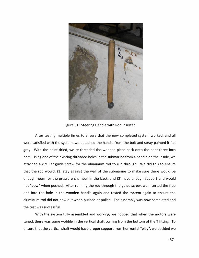
- 57 -
Figure 61 : Steering Handle with Rod Inserted
After testing multiple times to ensure that the now completed system worked, and all
were satisfied with the system, we detached the handle from the bolt and spray painted it flat
grey. With the paint dried, we re-threaded the wooden piece back onto the bent three inch
bolt. Using one of the existing threaded holes in the submarine from a handle on the inside, we
attached a circular guide screw for the aluminum rod to run through. We did this to ensure
that the rod would: (1) stay against the wall of the submarine to make sure there would be
enough room for the pressure chamber in the back, and (2) have enough support and would
not “bow” when pushed. After running the rod through the guide screw, we inserted the free
end into the hole in the wooden handle again and tested the system again to ensure the
aluminum rod did not bow out when pushed or pulled. The assembly was now completed and
the test was successful.
With the system fully assembled and working, we noticed that when the motors were
tuned, there was some wobble in the vertical shaft coming from the bottom of the T fitting. To
ensure that the vertical shaft would have proper support from horizontal “play”, we decided we

- 58 -
needed to fabricate a brace. To build the brace, we used some quarter inch aluminum sheet.
We cut the sides of sheet to match the angle of the port and starboard sides of the stern of the
submarine using a band saw. We placed the sheet on the sub and marked where the vertical
shaft would come up through the sheet. We then had Bill Bailey cut a channel out of the sheet
using a plasma cutter so that it could slide around the shaft snuggly. After this, we attached
angle iron to the aluminum sheet and through bolted the angle iron trough the sides of the
submarine. This addition gave the steering system added support and eliminated horizontal
movement in the vertical shaft of the T-bar assembly.
Figure 62 : T-Bar Brace
Potential Problems One possible problem in our steering assembly is that it is so simple. Simplicity was our
goal; however, this design may cause the pilot to put forth extensive amounts of force to move
the motors underwater, especially while moving. This need for an increased force by the pilot
is because of the increase in drag caused by the higher density of water compared to air.
Another possible problem with the system is the possibility for failure in the small rectangular
piece that attaches the aluminum rod to the triangular piece attached to the motor shaft. This

- 59 -
is a very light-weight piece that should work fine, but again the increased force the pilot might
have to put on the rod assembly could cause the rectangular piece to bend. However, there is
enough of the rectangular piece welded to the rod that even if the piece does bend, the rod
should still be able to push the shaft of the left motor backwards, resulting in a successful
execution of a right turn. An addition problem with the system is that the pilot of the
submarine might not be able to overcome the drag of the water, therefore might not be able to
steer the submarine at speed. This is a problem that can only be overcome by either having to
slow considerably for turning, or integrating hydraulics or electronics servos into the system to
apply addition forces. One final possible problem with the system is corrosion. We are not
very worried about corrosion in the hinge or rod, but instead the bolt used to anchor the
handle to the submarine. We used a stainless steel bolt to anchor the wooden handle to the
side, and if this bolt rusts, it could cause the handle to seize and not be able to move back and
forth. This should not be that big of a problem, because even if rust does occur, it will be able
to broken up and loosened to allow for movement. Also, if an excess of corrosion does occur
we will be able to replace the bolt at any time with a fresh one of any material available for very
cheap.
Future Suggestions We chose this particular assembly because we wanted simplicity. We figured the
simpler the design the better. Our thought process was that if the design was very simple,
there would be less of a chance for problems to occur in the system. Our steering assembly
was as simple and cost effective method we could think of. Our future recommendations for
the steering assembly would be to use some sort of either hydraulic or electronic servo system
to power the system. By doing this, the pilot would have to put much less effort into moving
the assembly with the increased drag from the water, especially at higher speeds. We were not
able to afford a system like this, but hopefully future groups will.

- 60 -
Dive Planes
It is very important that the pilot is able to control the vertical motion along with the
lateral motion. The MDU is also equipped with dive planes located at the front of the cockpit.
The dive planes are two identical hydro foils, which allow us to control the vertical angle at
which we travel. This control gives the pilot the ability to avoid underwater obstacles. When
the dive plans are angled down, the water flowing over the planes makes the noise of the sub
angle down. The opposite is true when rising in the water column. The pitch at which the sub
is allowed to maneuver is controlled by foot petals in the cockpit. This system works on the
same principal as ruder steering on a ship. The difference between the two is that a ship ruder
directs it in the horizontal plane allowing the boat to navigate port or starboard. The Marine
Diving Unit planes control navigation in the vertical plane allowing it to dive deeper or steer
towards the surface. The Initial dive plan design consisted of a single steel pivot rod with two
foot pedals welded directly onto the rod. The twin dive fins were salvaged from the original U-
Manatee and utilized to save on expenses. Straps were to be placed around the foot pedals and
the driver’s feet to make sure the two did not separate while underwater. The foot pedals were
designed to be larger than regular foot pedals because of the torque necessary to rotate the
dive planes while the sub is in motion. This design gives the pilot the vital control to handle the
MDU at all speeds. Moreover, the dive plans are main components for stability control. Since
we do not want the sub to roll, the dive plans act as stabilizers that keep the MDU upright.
Figure 63 : Initial Dive Plane Design

- 61 -
The initial design was simple and innovative, but it also had its drawbacks. Since the foot
pedals were to be mounted directly to the steel pivot rod this meant that the dive planes could
only rotate as much as the human ankle exerting force on them. After discussion of dive plane
design criteria we decided that a mere 45˚ of rotation that the ankle allowed was not sufficient
for vertical navigational needs. In the revised design we wanted to be able to direct the planes
completely upward and completely downward. This 180˚ of rotation allows for the submarine
pilot to have more precise control over the speed of a dive or accent. The pedals were also too
far forward when mounted directly on the rod; the driver had to fully extend to an
uncomfortable position in order to properly reach the pedals. We decided to extend the
controls one foot towards the stern to correct this. The rotation problem and pedal location
were both corrected in our final dive plane system. The final design also included independent
pedal controls that gave the driver the ability to pitch each dive plane independently and at
different angles. This feature was included so that the driver could compensate for any roll the
submarine might undergo. In order to make the planes independently operated the steel pivot
rod was cut in half and aluminum supports were custom built to hold matching bearing
assemblies that support the dive plane rod as it rotates.
The pedal mounting plate was fabricated from aluminum box stock that was trimmed
and cut down to fit the curvature of the Marine Diving Unit. The plate was held tightly to the
floor of the submarine by two securing bolts and epoxy resin. The securing bolts are
permanently fixed to the submarine, but the pedal mounting plate is locked on with four nuts, a
set of locking nuts on top of the plate and a set of washer nuts underneath it. The foot pedals
themselves are aluminum sheet attached to the mounting plate with stainless steel hinges. The
relocation of the pedals onto the fabricated platform brought the pedals lower and closer to
the driver, putting them in a more comfortable operating position. In order to get our desired
rotation in the dive planes we mounted three-inch long pivot bars off of each plane assembly.
The aluminum pivot bars were made adjustable by threading them so small hex-head screws
could be tightened to the steel pivot rod holding the dive fins. The aluminum pivot bars were
attached to the pedals with a custom made nine inch long u-bolt. Small round hinges were
fabricated onto the back of each pedal to secure one end of each u-bolt to each pedal. This also

- 62 -
allows it to still rotate freely as the pedal is pushed or pulled. Matching holes were drilled in the
end of the aluminum pivot bars to allow the opposite end of the u-bolt to rotate, but still exert
a moment on the steel pivot rod. A stopping bar was installed in front of the fin system to hold
the aluminum pivot bars from over rotating and allowing the fins into a backwards orientation.
The dive planes and pedals were made spring loaded by coiling a 12 inch long elastic cord
counterclockwise around the steel pivot rod several times. The two ends of the cord were
pinned, one to the hex-head screw on the aluminum pivot bar and the other to the inner wall of
the submarine. The elastic coil exerts a constant torque on the steel pivot bar that holds the
dive planes in a fully downward position. When force is applied to the pedals the steel bar
rotates slightly clockwise and directs the fins to an upward position. When force is removed
from the pedals the coils retract to their normal length, this brings the dive planes and pedal
controls back to their normal resting positions.
The vertical navigation controls now operate with 180˚ of freedom, giving the driver the
ability to direct each dive plane independently from a fully downward to a fully upward
position. Through trial and error and computer-aided design the initial design was revised and
perfected into our final assembly that is now installed in the submarine.
Figure 64 : Completed Dive Planes

- 63 -
Twin Propulsion with Rear Power Thruster
The Marine Diving Unit’s propulsion is designed around two identical fifteen volt trolling
motors and one larger trolling motor mounted directly in the rear of the sub. The two trolling
motors mounted on the t-bar give off thirty pounds of thrust each while the rear trolling motor
adds an extra forty five pounds of thrust. When the motors are in parallel, they give off a total
of one hundred five pounds of thrust. It is crucial that thrust on each side of the MDU is
identical. Any type of thrust differential thrust causes the sub to drive in circles or barrel role
uncontrollably. The trolling motors need to be carefully placed at a distance identically apart,
as well. The slightest miss calculation in position causes the sub to maneuver off course. One
hundred five total pounds of thrust makes it possible to travel at speeds from five to seven
knots. The available thrust gives us a safe maintainable cruising speed without the fear of
losing control. It is very important that the pilot is in complete control. The last thing we want
is for the pilot to panic underwater.
Figure 65 : Entire Propulsion Unit
Propeller guards were also added to the propellers for safety. Each guard was made
from cut sheet metal which was riveted together and hose clamped around the motor. These
guards also help us utilize the thrust from each motor. Finally they were spray painted black to
blend in with the body paint job.
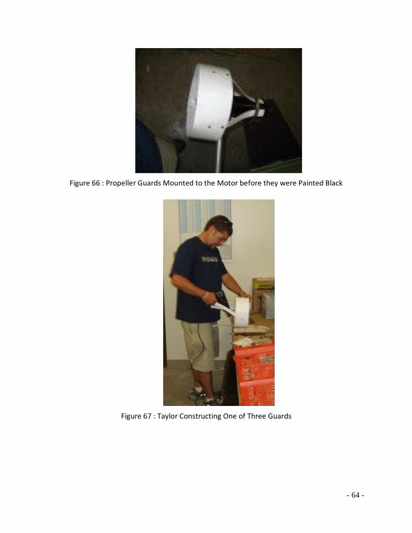
- 64 -
Figure 66 : Propeller Guards Mounted to the Motor before they were Painted Black
Figure 67 : Taylor Constructing One of Three Guards

- 65 -
Propulsion Tests
Numerous propulsion tests were administered over the span of the construction of the
MDU. The first propulsion test was performed once the dual trolling motors where screwed
into the t-bar system. The two motors were hooked up to a single control handle and then
connected to a battery. This test was conducted to see if the two trolling motors could run in
parallel off a single power source. An amp meter and a voltmeter were attached to the
connections to determine the amount of amps and volts needed to propel the dual motors.
Out of water there were twelve volts and 5 amps drawn, but there was an initial spike of
thirteen amps.
The second propulsion test was run off the hydrogen fuel cell. This test helped us if all
three motors could run safely off our hydrogen power source. We ran the hydrogen fuel cell
through a resister which gave us our needed twelve volts. Dr. Caraway was present for this
test. He was very pleased since the test was successful. He also gave us advice to test for the
draw of the motor in water.
The third test was to test the draw of all the motors underwater. The draw under water
is much greater that the draw out of water. This test was performed to see if the three motors
had a draw less than our maximum allowable fifty six amps that were produced by the fuel cell.
In this test we mounted the rear trolling motor to a 2X4. We decided to use the single rear
trolling motor because it produced the most amps out of water, compared to the dual trolling
motors. Instead of placing each trolling motor in the water and adding the total draw, we
decided to find the draw of the large trolling motor and then multiplying it by three to give us a
tiny factor of safety. Using hose clamps we secured the motor to the piece of wood. We took
the waterproof motor apparatus to the Florida Tech Waves Technology Lab. There we placed
the trolling motor in the water and connected it to our power source. We measured the draw
of the trolling motor at each speed both forward and reverse. In third gear forward, the amp
meter read seventeen amps. In fourth gear forward the motor drew 20 amps. We determined
that this would be our maximum forward speed. In second speed reverse, the amp meter
recorded twelve amps, which is safe to use.

- 66 -
Figure 68 : Mounting System for Underwater Amperage Test
Variable Speed Control
A variable speed control dial, which is located in the cockpit, gives us the ability to finely
change the power to trolling motors, thus it gives us the ability to change speeds. This handle
was designed by graduate student Joey Farrell. Using a potentiometer, he designed the dial to
change the resistance to the motors as the handle rotates. It is quite useful to be able to travel
at full throttle in open water and have the option to travel at lower speeds to sight see or test
in murky waters. This control is also equipped with a switch that allows us to reverse the
polarity, which permits use to travel at multiple speeds in reverse. A kill switch is placed in the
cockpit, as well. A kill switch is necessary to shut off the propulsion in cause of an emergency
or when the MDU approaches the deployment system. These controls keep the pilot safe while
they also protect collisions due to control lose.

- 67 -
Figure 69 : Variable Speed Controller
Along with the control handle, the MDU group will also add an LCD screen to the
cockpit. Joey Farrell’s circuit board design for our control handle makes it relatively easy to add
a LCD screen. This screen will be able to give us RPM readings, knots and amperage draw for
each of our trolling motors. We also plan to attach a small fan in the rear of the sub. This will
give us our cruising speed, which will be displayed on the screen. This design is used in many
jet ski systems.
Waterproofing
Waterproofing was an extremely important process in our project. Since water is a very
good conductor of electricity, it is to our safety and the safety of our equipment that we
waterproof all connections and motors. For the motors, we first added two layers of heat
resistant waterproof expandable foam. We used this because to completely waterproof the
motors we needed to use epoxy resin. This foam helps to prevent the liquid epoxy from
reaching the motor before it dries. It also will be able to withstand the high amounts of heat
that occurs when epoxy resin cures. Finally we added two more layers of epoxy to cure. The
rear trolling motor was simply placed in a cup of epoxy and allowed to harden.

- 68 -
Figure 70 : Rear Trolling Motor Curing in Epoxy
Waterproofing the controller was a tougher task. We needed to waterproof the power
connections on the controller, but the controller had to rotate to have variable speed controls.
To solve this problem, we came up with a pipe and gasket design. This consisted of a three inch
pipe with PVC end connector on each end. We cut a hole in each of the end connectors. On
one side the wires would be allows to exit, while the other side the rotating handle would exit.
The wire side was filled with epoxy for waterproofing. The other side was cut in half and a
rubber gasket was glued around the cut. This allowed the handle to rotate without water
seeping in.

- 69 -
Figure 71 : Variable Speed Control Handle in PVC Housing
Unfortunately during the waterproofing process of the control handle, epoxy somehow
seeped into the control handle which destroyed the connections. As a quick alternative, before
the symposium, we waterproofed a simple on/off switch for temporary solution to our
problem. We are currently working with Joey Farrell on a new variable control switch.

- 70 -
Figure 72 : Thruster Transom Mounted Trolling Motor
The Maker of our Dual Trolling Motors is Motorguide which is an affiliate of Mercury.
Table 1 : Specifications of Trolling Motors
Model T30
Thrust (Lb) 30
Speed control 5 Forward
Shaft (cm) 76
Steering Style Twist-Tiller

- 71 -
Transportation and Deployment System
Safe and damage-free transportation is the main focus when designing a trailer and
deployment system for the Marine Diving Unit. The DMES department is gracious enough to
supply us with the necessary equipment to design around. Our transportation device will be
designed around the old AUV trailer. The deployment system will be designed around the old
Human Powered Submarine launching device. The right adjustments will be made to insure
that the MDU will be transported as safe as possible.
The transportation trailer will have modified braces added to it. Since the MDU will
need to be quit heavy to overcome the large amounts of buoyancy, we will design specific
braces that will support the regions of the MDU that have the most weight. For example, the
area just back of center, where the pressure housing is located, will need to have more weights
than the other regions of the sub to overcome the buoyancy forces of the housing. If this area
is not securely braced, the sheer weight will likely cause structural failure. Our design will
include side braces as well as bottom supports. The more contact area the MDU has with the
trailer, the more the weight can be evenly displaced. While on the braces, the MDU will be
secured with a serious of latches, so it does not slide around. We want to restrict as much
movement as possible. The trailer is necessary for us to transport the MDU to areas where the
water clarity is ideal for testing.
The deployment system is another piece of equipment used in previous projects. This
amphibious trailer with large wheels that make is possible to be transported on land. There are
also to large pontoons on both sides of the trailer, giving it the ability to float as well. There is a
wench system that moves the pontoons vertically. This system makes it possible to deploy the
MDU at sea. The deployment system will drag behind a boat to the designated testing areas.
We have run into some problems with the design of the deployment system. The size of the
pontoons, make the trailer to wide for highway transportation. The device is solely for
deployment around the FIT Anchorage area. We need to figure out some way to transport the
deployment system on land, since it does not have a trailer hitch or any type of towing system.
We have also run into another problem: As of right now, our group does not have access to a

- 72 -
boat to tow the deployment system. One of the last steps of the design project will be to insure
access to a boat for testing purposes.
Figure 73 : Trailer Frame Design
Figure 74 : Finalized Trailer

- 73 -
Figure 75 : Deployment System
Possible Testing Sites
Testing zones go through a strenuous selection process. Various parks and beaches, all
along the Space and Treasure Coast, went through an integration process. It is important to
have multiple sites in case conditions are not ideal. During this process we looked for certain
criteria, such as, accessibility, boat traffic, distance, water clarity, water current, surface wave
height, and local government cooperation. The areas that best matched these categories were
chosen as our testing sites. In the end, three different testing zones were selected.
The first testing zone chosen is in the Anchorage, west Manatee Park region. This region
was chosen because it has the best accessibility. The FIT Anchorage is fully equipped with a
boat ramp with boat access. This site was also chosen because it harbors our deployment
system. As stated earlier, the deployment system cannot be transported via highway. The city
of Melbourne recently has given us permission to use the area of Manatee Park, west of the
railroad tracks. Their only request is that we use a dive flag during testing. The only
disadvantage to testing in this area is that the water visibility is poor.

- 74 -
In our next testing site, water clarity was main criterion. We decided that the Tracking
Station area in Vero Beach would be ideal. This area is home to a FIT laboratory, which gave us
support from the City of Vero Beach to test. This zone also has full beach access making it easy
to transport the MDU from the trailer to the ocean. Lifeguards are also present at this beach,
which important in case of emergency. Some disadvantages to using this area are larger than
ideal surface waves that cause murky conditions.
Testing zone number three is Pepper Park, in Fort Pierce. We chose this area because of
familiarity. Members of our group have spear fished the area multiple times and know the
reefs very well. We also know that the visibility is often larger than twenty feet. We will feel
more secure seeing where we are going. This area was also chosen because of accessibility.
Some of the disadvantages are distance and we have not yet received permission from the City
of Fort Pierce to use this site.
Figure 76 : Overall Map of Testing Sites

- 75 -
Figure 77 : Testing Zone #1
Figure 78 : Testing Zone #2
Figure 79 : Testing Zone #3
- 76 -
Testing Procedure
Once the project has been finalized, we hope to test the submarine about four times.
The night before any test we will do a final inspection of the submarine to make sure that
nothing has been altered. We will also keep a close eye on the weather for safety reasons.
Whenever we are testing we will have one scuba diver inside the submarine as a pilot, three
divers around the submarine in case of emergency, and one man at the surface either
snorkeling, or recording data. This will ensure that our safety is never compromised during the
testing process.
Our first test will be in Southgate pool. This test will be a basic test consisting of
deployment, buoyancy, propulsion and steering. This test will allow us to find any major
problems that may happen in an open environment system. We will be underwater for
approximately an hour. Our biggest problem with this test is going to be the deployment of the
submarine due to the face that Southgate has no ramp into the pool. This will be a very
controlled test on the submarine. The checklist we have created for Southgate pool is located
in Appendix A.
Our open water testing procedures vary from the testing procedures in Southgate. We
will have to keep a close watch on the weather the day of the test. Waves and strong winds
would be very detrimental to any testing. When diving in open water, we will first need to do
an inspection of the surroundings, including underwater. If there is a hazard in the water we
will first try and nullify the situation, or reschedule the dive for a different site. This inspection
will be our first dive of a test day in open water. Once we deem the site safe, we will begin the
charge of the fuel cell. The fuel cell will take about five minutes to build up an initial charge.
During this time we will be preparing the rest of the submarine for deployment. After the fuel
cell is running on its own we will seal the pressure chamber. This will take approximately half
an hour. We will need to tighten every bolt and run visual inspections. Once we have the fuel
cell running and placed in the housing in the submarine we will place the pilot in the submarine
and perform checks on the steering, dive planes and throttle. At this time two of the safety
divers will then go into the water make sure everything is still clear of hazards. If everything is
working smoothly we will then put the cockpit hatch on and begin lowering the submarine into

- 77 -
the water. Once in the water we will do initial checks for leaks and make sure all components
are still working. The tasks we wish to accomplish for each individual dive will govern where we
go from there. At max we will stay underwater with the submarine for 90 minutes. After 90
minutes we will gradually inflate the lift bags and begin to surface. We will need to take a three
minute stop at 15 feet if dove more than that. Once we have waited our three minutes, we will
continue towards the surface. After the MDU has surfaced we will completely fill the lift bags
with air. The safety divers will then escort the submarine back to the position from which it
was launched.
Once we get the MDU back to our facilities, we will wash it down with fresh water, to
get rid of all the salt or other harmful accumulations we have acquired during the dive. A dive
log will then be filled out for the MDU recording the time and operations underwater.

- 78 -
Long Term Goals
Our main long term goal is to have this submarine completely integrated with steering,
propulsion, buoyancy, a fuel cell power plant, and controls. We have made a tremendous
amount of progress but have not finished the project thus far. We would like to run about three
or four tests once the submarine is completed. We plan to have our first test in Southgate pool
for safety reasons. The other three tests could be done at any of the test sites. Our final goal is
to take the MDU to the international submarine races in 2009. We would like to try and get
other schools and organizations to push towards the design of fuel cell powered submarines. If
we could get other schools to participate in the fuel cell races, the funding and sponsorship
would greatly increase. Multiple members of our group are looking forward to continuing this
project in the fall as a Special Topics in Ocean Engineering course.

- 79 -
Finances
We were given an initial balance of $1250 to spend on this project. We have spent
$1140. We have been in contact with multiple local businesses and have been successful in
getting donations for materials and labor valued at over $400.00. A list of our current expenses
and our donations can be found in Appendix D. We have also included the brochure we have
been handing out to companies in Appendix E.

- 80 -
Safety
Machine Shop Work
Florida Tech has established basic rules that must be followed while working at the on
campus machine shop. A machine shop certification is required to enter and use any equipment
in the shop; appointments for this class are made with shop supervisors. The certification takes
a couple hours and covers basic machine knowledge and safety. Students are required to have
a supervisor on site at all times and must work in groups of at least two people. Sneaker and
sandals are not prohibited in the shop area; work boots and shoes are recommended. Safety
glasses must be worn over the eyes at all times, hair
must be pulled back and no loose fitting clothes. Ear
protection will also be worn if work or machinery
produces harmfully loud noise. If accidents or machine
problems occur then they should be reported right away
to the supervisor in order for the next course of action to
be determined. If working with a possible harmful
material a Material Safety Data Sheet must be provided so risks are known and proper
precautions can be made. When working with fiberglass or any potentially harmful material
respirators should be worn along with glasses and gloves. Contact with small fiberglass particles
can cause respiratory problems and other bodily irritations. No horseplay or arguing will be
allowed in the shop seeing as it is a place of serious work and dangerous machinery.
Simple power tool safety is also important when working on projects. It is important to
select the proper tool for the job at hand, using proper tools will not only do the job easier; it
will decrease the chance of it braking and the operator becoming injured. Never carry tools by
cord or hose and keep electrical cords away from heat or sharp edges. Practice disconnecting
tools when not in use so that nothing can unexpectedly jump to life. Electrical tools need to be
grounded to avoid electrical shock and should never be used in damp or wet areas. These rules
and guidelines will be followed throughout engineering design work to create a safe and
productive atmosphere.
Figure 80 : Cutting Piece for Hatch
- 81 -
Scuba (FIT/PADI)
Our group has been PADI open water dive certified, and common PADI guidelines will be
followed while diving. Although we are only planning on diving to a depth of about 20 feet with
the submarine, we will all use dive tables to calculate safe bottom times. Common
communication signals such as distress, low on air, and out of air will be reviewed before each
dive. Buddy diving will be utilized for an extra measure of safety; we will check over each
other’s equipment and buddy contact will be maintained throughout the dive. If buddies lose
one another the plan is to search for approximately one minute and then surface if submarine
or buddy is not located. As stated earlier we are not planning on diving very deep, but a safety
stop at 15 feet for 3 minutes will still be carried out at the end of every submarine test.
Florida Tech requires a special FIT dive certification when diving for school related
activities. This certification has several key components that must be carried out before an FIT
dive card can be obtained. A pool skills test is required along with a written dive
table/knowledge test. A dive physical, proof of dive insurance, and CPR certification must all be
submitted to the school as well. The school practices some added safety techniques that are to
be followed as well. A dive director and dive supervisor is assigned to each dive group ahead of
time, and these people are responsible for the pre-dive checklist and submitting it after the
dive. The pre-dive checklist consists of communication procedures, location of first aid kit,
emergency ascent procedures, dive plan review, and equipment inspection. Before dives a
faculty member in charge must submit a project proposal. This proposal needs to outline the
dive location, time/date, and mission of the dive. These dive guidelines and rules will be strictly
implemented during the submarine test dives in an effort to be as safe as possible.
Marine Diving Unit Safety Components and Procedure
The submarine will be equipped with a cockpit hatch release consisting of four elastic
straps that go through the Plexiglas hatch and down to the sides of the fiberglass shell. The
elastic straps are circular and hook to a point inside and outside the body of the submarine; this
makes it possible to unhook the cockpit hatch from the inside and the outside. In the event
that the pilot needs to bail out, the elastic can be quickly unhooked and the hatch can easily lift
off. A small pony bottle with regulator will also be located in the forward cockpit area for quick

- 82 -
emergency air access. The submarine will also include a ballast weight system and lift bag
system. Ballast weights are to be secured to the hull and inside the submarine behind the
pressure chamber. We recommend that a droppable ballast system be considered if this project
is to be continued. That way if there was an emergency and positive buoyancy is needed a
ripcord could be pulled in the cockpit to drop the weight. The positive buoyancy created by the
air inside the pressure chamber would then carry the craft to the surface. A lift bag system will
also be utilized for controlled slow ascents.
When testing the Marine Diving Unit at least three extra dive personnel will follow the
submarine to monitor its progress and provide assistance if needed. Two divers will be
positioned at the edge of the dive area and one will stay with the submarine at all times. Boat
support will be used to monitor traffic and dive flags will be deployed to mark off the test area.
The testing area will need water with visibility of 50 feet or more, so that all dive personnel can
always see each other and the submarine. Current and depth are also deciding safety factors on
testing locations. Minimal current speed is important so that no team members become
separated from the group. The dive location must also be of appropriate depth for our design
running depth of about 20 feet. If the submarine malfunctions and is forced to the bottom the
location must allow for the bottom depth to be safe for a human diver. Test sites will vary
depending on the individual conditions at the time of a test. Dive personnel will overview
weather forecasts and sea reports before any test is attempted to ensure proper testing
conditions are met.
Surfacing Procedures: (Normal Ascent)
1. Proceed to 15 feet depth and perform 3-minute safety stop.
2. Slowly add burst of air to submarine lift bag to induce positive buoyancy and a slow
movement toward the surface (remember to keep breathing at all times)
3. Once positive buoyancy and upward movement is taking place, slowly bleed off air to
maintain a slow ascent. (Do not exceed 60 ft/min rise)
4. Once at surface inflate lift bags

- 83 -
Surfacing Procedures: (Emergency Ascent: Out of air or Pressure tank leak)
1. Switch to emergency pony bottle regulator and unlatch bottle from sub
2. Set motor control to neutral position and/or cut power
3. Unhook hatch release and push hatch open
4. Pull ballast ripcord to drop weight (drop away weights recommend to be added)
5. Bail out of submarine with pony bottle in hand and signal near-by buddy
6. Proceed to the 15 ft depth and perform 3-minute stop (monitor air tank pressure)
7. Surface and proceed towards floating submarine
Surfacing Procedures: (Emergency Ascent: Pony bottle & main bottle out of air)
1. Set motor control to neutral position and/or cut power
2. Unhook hatch release and push hatch open
3. Pull ballast ripcord to drop weight (drop away weights recommend to be added)
4. Bail out of submarine and signal nearby buddy to air share (if no dive personnel are
near, perform an emergency swimming accent exhaling all the way to the surface)
*If divers are near continue procedure
5. Proceed to the 15 ft depth and perform 3-minute stop (monitor air tank pressure)
6. Surface and proceed towards floating submarine
Surfacing Procedures: (Emergency Ascent: Loss of power or navigation)
1. Set motor control to neutral position and/or cut power if power not already off
2. Slowly add burst of air to submarine lift bags to induce positive buoyancy and a slow
movement toward the surface (remember to keep breathing at all times)
3. Proceed to 15 feet and bleed off air to attain neutral buoyancy for 3-minute safety stop

- 84 -
4. Slowly add burst of air to submarine lift bags and once positive buoyancy and upward
movement is taking place, slowly bleed off air as needed to maintain a slow ascent.
5. Once at surface inflate lift bags.

- 85 -
Table of Figures
Figure 1 : Human Powered U-Manatee ................................................................................................ - 3 - Figure 2 : David Taylor Modeling Basin in Bethesda, Maryland............................................................. - 6 - Figure 3 : Hydrogen Powered Submarine ............................................................................................. - 8 - Figure 4 : Initial Solid Design ................................................................................................................ - 9 - Figure 5 : See Through Initial Design .................................................................................................... - 9 - Figure 6 : Current Submarine Design.................................................................................................. - 10 - Figure 7 : Dive Plane Repair ............................................................................................................... - 11 - Figure 8 : Back Side Hatch .................................................................................................................. - 12 - Figure 9 : Finished Nosecone ............................................................................................................. - 13 - Figure 10 : Final Paint Job .................................................................................................................. - 14 - Figure 11 : Final Paint Job .................................................................................................................. - 14 - Figure 12 : Pro Engineering Drawing of Cockpit Hatch ........................................................................ - 15 - Figure 13 : Finished Plexiglas Hatch ................................................................................................... - 16 - Figure 14 : Sir William Grove.............................................................................................................. - 18 - Figure 15 : Ballard Fuel Cell ................................................................................................................ - 19 - Figure 16 : How A Fuel Cell Works ..................................................................................................... - 21 - Figure 17 : Pressure Testing Apparatus .............................................................................................. - 22 - Figure 18: Connecting the Fuel Cell to the Motors ............................................................................. - 23 - Figure 19 : Initial ProE Drawing of Pressure Chamber ........................................................................ - 26 - Figure 20 : Face of Pressure Chamber ................................................................................................ - 27 - Figure 21 : Initial Condition of Air Receiver Tank ................................................................................ - 30 - Figure 22 : Initial Condition of Steel Plate .......................................................................................... - 30 - Figure 23 : Steel Materials after Sandblasting .................................................................................... - 31 - Figure 24 : Small Tank Section Ready for Cutting ............................................................................... - 31 - Figure 25 : Large Tank Section Ready for Cutting ............................................................................... - 32 - Figure 26 : Sections Removed by Cutting ........................................................................................... - 32 - Figure 27 : Machinist Bill Bailey Cuts Air Tank .................................................................................... - 32 - Figure 28 : Design for Flange.............................................................................................................. - 33 - Figure 29 : Flange Ready for Cutting .................................................................................................. - 33 - Figure 30 : Machinist Bill Bailey Cuts Out Flange ................................................................................ - 33 - Figure 31 : Grinding Flanges Smooth.................................................................................................. - 34 - Figure 32 : Drilling Through Bolt Holes in Flange ................................................................................ - 34 - Figure 33 : Machinist Bill Bailey Welding Flange onto Pressure Chamber ........................................... - 35 - Figure 34 : Grinding Welding Residue ................................................................................................ - 35 - Figure 35 : Template for Fuel Cell Mounting System .......................................................................... - 36 - Figure 36 : Fuel Cell Mounting Feet ................................................................................................... - 36 - Figure 37 : Fuel Cell Mounted in Pressure Chamber ........................................................................... - 36 - Figure 38 : Mounting System for DC to DC Converter ......................................................................... - 37 - Figure 39 : DC to DC Converter Mounted in Chamber ........................................................................ - 37 - Figure 40 : Pressure Chamber with Fuel Cell and Converter ............................................................... - 38 - Figure 41 : Hydrogen Tank in Chamber .............................................................................................. - 39 - Figure 42 : Horseshoe Mounting System ............................................................................................ - 39 - Figure 43 : Painting the Pressure Chamber ........................................................................................ - 40 - Figure 44 : Pressure Relief Valve ........................................................................................................ - 40 - Figure 45 : Power Output Wire Port ................................................................................................... - 41 - Figure 46 : PVC Helix Reinforced Tubing ............................................................................................ - 41 -

- 86 -
Figure 47 : Air Input System ............................................................................................................... - 42 - Figure 48 : Test Setup at Southgate Pool ............................................................................................ - 43 - Figure 49 : Chamber Hose Connection ............................................................................................... - 43 - Figure 50 : Chamber in the Water ...................................................................................................... - 44 - Figure 51 : Pressure Chamber Draining .............................................................................................. - 44 - Figure 52 : Scrap Ballast Metal ........................................................................................................... - 46 - Figure 53 : Buoyancy Compensator.................................................................................................... - 47 - Figure 54 : Joey Farrell's Initial Ballast Design .................................................................................... - 48 - Figure 55 : Original Steering Design ................................................................................................... - 50 - Figure 56 : Original Steering Design ................................................................................................... - 50 - Figure 57 : Materials Used For Steering Model .................................................................................. - 52 - Figure 58 : Working Steering Model ................................................................................................... - 52 - Figure 59 : Ball Bearing and Bottom Mounting Hardware .................................................................. - 55 - Figure 60 : T-Bar Assembly................................................................................................................. - 55 - Figure 61 : Steering Handle with Rod Inserted ................................................................................... - 57 - Figure 62 : T-Bar Brace....................................................................................................................... - 58 - Figure 63 : Initial Dive Plane Design ................................................................................................... - 60 - Figure 64 : Completed Dive Planes ..................................................................................................... - 62 - Figure 65 : Entire Propulsion Unit ...................................................................................................... - 63 - Figure 66 : Propeller Guards Mounted to the Motor before they were Painted Black ........................ - 64 - Figure 67 : Taylor Constructing One of Three Guards ......................................................................... - 64 - Figure 68 : Mounting System for Underwater Amperage Test ............................................................ - 66 - Figure 69 : Variable Speed Controller ................................................................................................. - 67 - Figure 70 : Rear Trolling Motor Curing in Epoxy ................................................................................. - 68 - Figure 71 : Variable Speed Control Handle in PVC Housing ................................................................. - 69 - Figure 72 : Thruster Transom Mounted Trolling Motor ...................................................................... - 70 - Figure 73 : Trailer Frame Design ........................................................................................................ - 72 - Figure 74 : Finalized Trailer ................................................................................................................ - 72 - Figure 75 : Deployment System ......................................................................................................... - 73 - Figure 76 : Overall Map of Testing Sites ............................................................................................. - 74 - Figure 77 : Testing Zone #1 ................................................................................................................ - 75 - Figure 78 : Testing Zone #2 ................................................................................................................ - 75 - Figure 79 : Testing Zone #3 ................................................................................................................ - 75 - Figure 80 : Cutting Piece for Hatch ..................................................................................................... - 80 -

Appendix A
Marine Diving Unit Checklist
Southgate Pool
1. Visually inspect the submarine hull for any leaks or cracks
2. Prep the fuel cell
3. Close the pressure housing
4. Check steering, throttle and dive planes
5. Prepare SCUBA gear for water entrance
6. Two safety divers enter water
7. Place the submarine in the water
8. Wait for submarine to partially fill with water
9. Attach the ballast to the submarine and achieve neutral buoyancy
10. Once completely submerged, inspect for leaks
11. Test steering and dive planes
12. Increase throttle and begin tests
13. Continte to check for leaks
14. Once completed gradually fill lift bags and begin ascent
15. Once surfaced completely fill the lift bags
16. Get the submarine out of the water
17. Rinse off with fresh water
18. Do one last inspection for leaks or any cracks

II
Appendix B
Marine Diving Unit Checklist
Open Water Dive Site
1. Visually inspect the submarine hull for any leaks or cracks
2. Perform an initial dive in the water and check for hazards
3. Prep the fuel cell
4. Close the pressure housing
5. Check steering, throttle and dive planes
6. Prepare SCUBA gear for water entrance
7. Two safety divers enter water
8. Place the submarine in the water
9. Wait for submarine to fill with water
10. Once completely submerged, inspect for leaks
11. Test steering and dive planes
12. Increase throttle and begin tests
13. Continte to check for leaks
14. Once completed gradually fill lift bags and begin ascent
15. Once surfaced completely fill the lift bags
16. Escort the submarine to the boat entrance
17. Get the submarine out of the water
18. Rinse off with fresh water
19. Do one last inspection for leaks or any cracks

Appendix C
Appendix C-1 : Initial Timeline
Appendix C-2 : Timeline as of April 25, 2008

Appendix D
Purchased Items
Date Item Item Use Location Member Quantity Cost
27-Feb 1.5" Cap test chamber Home Depot David 1 $2.69
27-Feb 1" plug test chamber Home Depot David 4 $5.08
27-Feb 1/2" plug test chamber Home Depot David 1 $0.94
27-Feb 3/4" plug test chamber Home Depot David 1 $1.10
10-Mar fasteners test chamber Ace Hardware David 1 $0.85
10-Mar fasteners test chamber Ace Hardware David 2 $1.40
10-Mar caulk test chamber Ace Hardware Ryan 1 $1.99
14-Mar fasteners test chamber Ace Hardware David 8 $1.36
16-Mar galvanized plug test chamber Home Depot Ryan 2 $2.20
16-Mar galvanized plug test chamber Home Depot Ryan 4 $5.08
30-Mar wood screws test chamber stand Home Depot Taylor 5 $4.90
30-Mar 4x4s test chamber stand Home Depot Taylor 1 $8.97
11-Apr plexiglas canopy Plastics Design Ryan 1 $160.00
12-Apr trolling motors propulsion Port Supply Ryan 2 $193.98
14-Apr 3 hole punch notebook Office Depot David 1 $2.99
14-Apr Dividers notebook Office Depot David 1 $3.49
14-Apr binder notebook Office Depot David 1 $8.99
15-Apr Jigsaw Blades Sub hatch Home Depot David
$13.87
17-Apr tank shipping pressure chamber UPS
$196.88
21-May blue wire propulsion Ace Hardware Ryan 10 ft $2.90
21-May red wire propulsion Ace Hardware Ryan 10ft $2.90
21-May yellow wire propulsion Ace Hardware Ryan 10ft $2.10
21-May black wire propulsion Ace Hardware Ryan 10ft $2.10
21-May Al sheets steering Ace Hardware Ryan 2 $4.58
21-May Galvanized Tee steering Ace Hardware Ryan 1 $2.49
21-May 3/16" eye bolt steering Ace Hardware Ryan 5 $8.95
21-May mending brace steering Ace Hardware Ryan 1 $6.49
21-May Al rod (4' x 1/4") steering Ace Hardware Ryan 2 $6.58
22-May radial ball bearing steering Grainger Ryan 1 $20.16
27-May pipe threading motor brackets Tuckers Plumbing David 2 $10.00
29-May pressure valve pressure chamber Grainger Taylor 1 $10.34
29-May pigtail wires propulsion Grainger Colin 1 $9.87
30-May sand paper nose cone Home Depot Ryan 2 $9.94
30-May electric fasteners propulsion Ace Hardware Justin 1 $2.49
30-May bolts steering Ace Hardware Justin 6 $2.22
30-May bolts steering Ace Hardware Justin 4 $6.16
30-May bolts steering Ace Hardware Justin 4 $1.12
30-May bolts steering Ace Hardware Justin 4 $0.64
4-Jun Sandblasting sand pressure chamber East Coast Sandblasting Taylor 1 $20.00
11-Jun Marine Grade Caulk hatch set up West Marine Ryan 1 $12.49
11-Jun Marine Grade Putty hatch set up West Marine Ryan 1 $12.39
19-Jun 30" BC inflator Hose pressure chamber Hatts Diving Headquarters Taylor 1 $30.55

V
19-Jun Air Chuck Adapter pressure chamber Hatts Diving Headquarters Taylor 1 $4.95
19-Jun 1/4" needle valve pressure chamber Grainger Taylor 1 $5.90
19-Jun 1/4" Barb fitting pressure chamber Grainger Taylor 1 $0.90
19-Jun structural Marine Putty hatch set up West Marine Ryan 1 $13.29
20-Jun Reducing Bushing pressure chamber Grainger Taylor 1 $2.57
20-Jun 1/4" Barb fitting pressure chamber Grainger Taylor 1 $0.90
25-Jun bolts pressure chamber Lowes David 4 $14.16
25-Jun locking nuts pressure chamber Lowes David 2 $7.42
26-Jun 2" brass check valve pressure chamber Grainger
MFP Credit 1 $43.47
27-Jun stainless rod chamber clamps Ace Hardware Colin 1 $16.49
27-Jun fasteners chamber clamps Ace Hardware Colin 4 $10.20
27-Jun bungee dive planes Ace Hardware Colin 2 $1.58
3-Jul 2" coupling pressure chamber Ace Hardware David 1 $4.29
3-Jul clasps pressure chamber Ace Hardware David 1 $4.29
3-Jul hinges pressure chamber Ace Hardware David 1 $4.29
8-Jul expandable foam propulsion Home Depot Ryan 1 $8.98
11-Jul Group Shirts Group Scubadorable Justin 5 $106.00
14-Jul adhesive hooks hatch set up Home Depot Taylor 2 $5.94
14-Jul female wire connectors propulsion Home Depot Taylor 1 $9.25
14-Jul 3/8" pipe cap pressure chamber Home Depot Taylor 1 $2.92
14-Jul eyebolts pressure chamber Home Depot Taylor 1 $1.98
14-Jul machine bolts steering Home Depot Taylor 1 $0.98
14-Jul 3/8" pipe nipple pressure chamber Home Depot Taylor 1 $4.29
14-Jul 1/2" sling tubing hatch set up Hatts Diving Headquarters Colin 3ft $6.00
15-Jul Rustoleum primer pressure chamber Ace Hardware David 1 $4.49
15-Jul 1 x 3/4 hose barbs pressure chamber Ace Hardware David 2 $9.58
15-Jul tie down straps steering Ace Hardware David 2 $2.58
20-Jul scuba rentals MFP cruise Hatts Diving Headquarters Ryan 2 $40.00
Donations
Part Donated Donor Approximate Value ($) Use
Air Receiver John Paul 200 Pressure Chamber
Plexiglas Labor Plastics Design & Mfg., Inc 340 Hatch
Sandblasting Labor East Coast Sandblasting 90 Pressure Chamber
Paint Job Maaco 1200 Body
Hose Kuriyama of America 140 Pressure Chamber
Shirts Scubadorable 65 Presentation
Dive Rentals Hatts Diving 30/per dive Testing
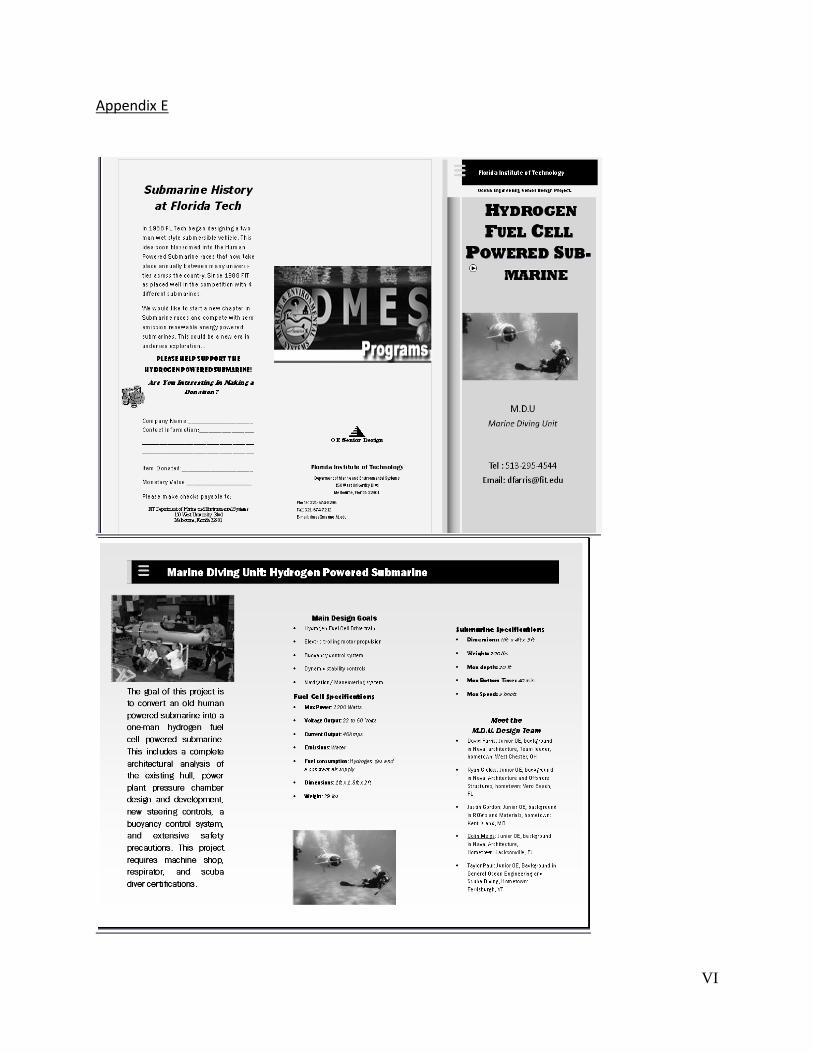
VI
Appendix E

VII
References
www.dt.navy.mil/
http://getenergysmart.org/Files/Schools/Hydrogen/3HistoryofHydrogen.pdf
http://estarfuturecorp.com/fcworks/SirWilliamGrove.png
http://www.mne.psu.edu/me415/spring07/EcoB/image002.jpg
http://www.hydrogenhighway.ca/upload/images/Science/sheme_001.gif
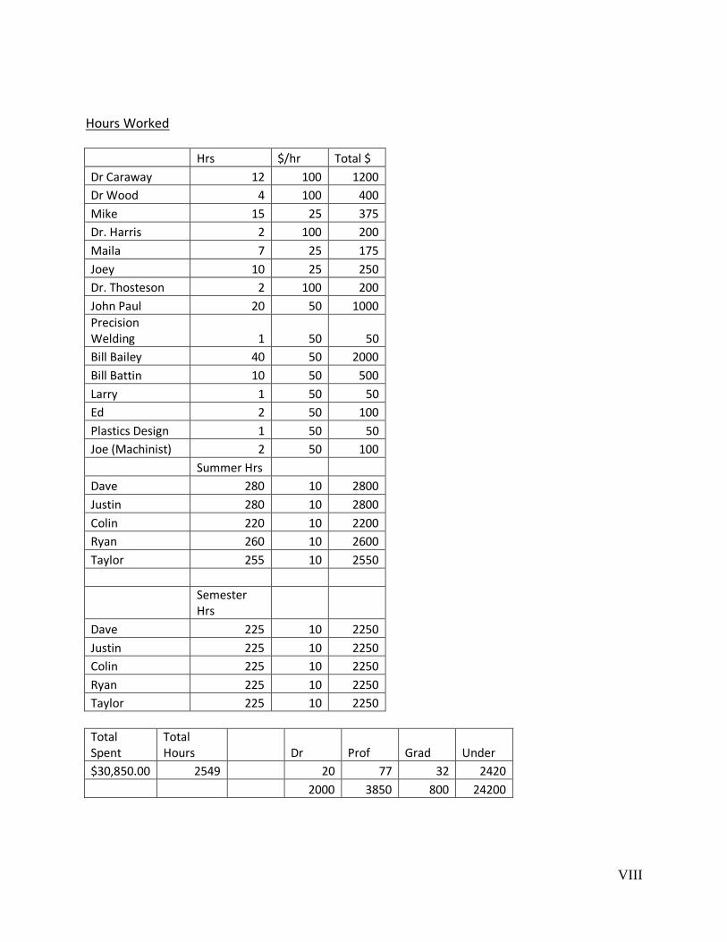
VIII
Hours Worked
Hrs $/hr Total $
Dr Caraway 12 100 1200
Dr Wood 4 100 400
Mike 15 25 375
Dr. Harris 2 100 200
Maila 7 25 175
Joey 10 25 250
Dr. Thosteson 2 100 200
John Paul 20 50 1000 Precision Welding 1 50 50
Bill Bailey 40 50 2000
Bill Battin 10 50 500
Larry 1 50 50
Ed 2 50 100
Plastics Design 1 50 50
Joe (Machinist) 2 50 100
Summer Hrs
Dave 280 10 2800
Justin 280 10 2800
Colin 220 10 2200
Ryan 260 10 2600
Taylor 255 10 2550
Semester Hrs
Dave 225 10 2250
Justin 225 10 2250
Colin 225 10 2250
Ryan 225 10 2250
Taylor 225 10 2250
Total Spent
Total Hours
Dr Prof Grad Under
$30,850.00 2549
20 77 32 2420
2000 3850 800 24200