Embed Size (px)
Citation preview
Page 1 of 25
Florida Department of Transportation District Four
Drainage Connection Permits
Applicant and Reviewer
Guide
Last Revision September 24, 2012 by Georgi Celusnek

Page 2 of 25
TABLE OF CONTENTS
CHAPTER ONE: THE RULES……………………………………………………Pages 3 to 8
Drainage Connection Permit Jurisdiction and Purpose
Improvements Requiring a Drainage Connection Permit
Drainage Connection Permit Exceptions
Drainage Connection Permit Exception or Application Routing Process
District Four Drainage Connection Permit Criteria
CHAPTER TWO: THE APPLICATION PACKAGE……………………………Pages 9 to 16
List of Items in a Complete Permit Application Package
Tips for Select Items
Form 850-040-06
The Soils Report
The PG&D Plans
The On-Site Drainage Report
The Department’s Right of Way Impacts Report
CHAPTER THREE: THE REVIEW GUIDE………………………………………Pages 17 to 18
Part One: The Site
Type One: No Discharge to the Department’s Right Of Way
Type Two: Allowable Discharge to the Department’s Right Of Way
Part Two: The Department’s Right Of Way
CHAPTER FOUR: THE REVIEW CHECKS………………………………………Pages 19 to 20
CHAPTER FIVE: THE EQUATIONS AND SAMPLES …………………………Pages 21 to 23
CHAPTER SIX: DISTRICT FOUR………………………………………………… Pages 24 to 25

Page 3 of 25
CHAPTER ONE: THE RULES
I. DRAINAGE CONNECTION PERMIT JURISDICTION AND PURPOSE
A. The Department’s jurisdiction for Drainage Connection Permits is defined in Florida
Administrative Code (FAC) Rule Chapter 14-86. The rule was lasted rewritten and
adopted on January 20, 2009.
Find Rule Chapter 14-86 at
https://www.flrules.org/gateway/ChapterHome.asp?Chapter=14-86
B. The purpose of Rule Chapter 14-86 is to ensure safe conditions and the integrity of
the Department's transportation facilities and to prevent an unreasonable burden on lower
properties by providing standards and procedures for drainage connections from the
properties adjacent to the Department's right of way.
C. Rule Chapter 14-86 requires demonstration that there is no increase of run-off
discharge to the Department’s right of way from the proposed improvements. Therefore,
the allowable discharge to the Department’s right of way is based on the approach known
as pre-development versus post-development.
II. IMPROVEMENTS REQUIRE A DRAINAGE CONNECTION PERMIT
Any site abutting the Department’s right of way or easement, undergoing development or
changing grades is subject to this rule unless the improvement qualifies for an exception.
III. DRAINAGE CONNECTION PERMIT EXCEPTIONS
A permit application is not required for projects that qualify for an exception. However,
to receive written verification of the exception, a completed Drainage Connection Permit
Application (Form 850-040-06) and appropriate back up materials are required.
A. Exception criteria follow:
1. A single family home, not being developed or improved as part of a larger
common plan of improvement.
2. Agricultural land, not being developed or improved as part of a larger
common plan of improvement.
3. Sites separated from the Department’s right of way by an existing canal,
providing that the proposed development is not draining towards the driveway
connection to the State Road.
4. Projects that reduce the impervious area without reducing the existing storage
of the site and changing the existing grades.
B. Exception packages are submitted to the appropriate Operations Center and shall
include the following:
Page 4 of 25
1. Completed Drainage Connection Permit Application (Form 850-040-06) with
Exception checked on Part 1/Page 2.
2. Recent survey plans, certified by a Professional Land Surveyor Certified in
the State of Florida.
3. Scaled paving, grading and drainage plans reflecting pre-development and
post-development conditions. The plans shall be signed and sealed by a
Professional Engineer certified by the State of Florida.
4. Land-use area calculations.
IV. DRAINAGE CONNECTION PERMIT EXCEPTION OR APPLICATION TRAIL
A. Broward, Palm Beach, Martin or St Lucie County Projects
1. An applicant may schedule a pre-application meeting to review the Drainage
Connection Permit process, applicable criteria and/or requirements, as well as
ongoing Department roadway projects adjacent to the site. Department
representatives from the Drainage Office, the District Permits Office, the
appropriate Operations Center, or other offices will attend as needed.
2. An applicant submits complete permit package to the appropriate Operations
Center.
Find Operations Center Information in CHAPTER SIX
3. The Operations Center assigns a permit number and reviews the package for
completeness. The Operations Center forwards the complete package to the
Drainage Office. The Drainage Office logs the package into the Drainage
database and assigns a reviewer.
4. The Drainage Office reviewer checks the application, computations, and plans
for compliance with the procedures established in Rule Chapter 14-86, these
guidelines, acceptable drainage design practice and Department design criteria.
The Drainage database Project Summary Form is completed for the project. The
Drainage Office Engineer completes the review within two-weeks.
5. If additional information is required and/or computations or plans need
modification, a Request for Information (RFI) is sent to the applicant’s Engineer.
A copy of the RFI is sent to the Operations Center. The Operations Center and
District Permits Office are informed of changes requested by the Drainage Office
which affect the driveway plans. The applicant’s Engineer submits four (4)
copies of the additional information directly to the Drainage Office. Upon receipt
of the additional information, the log-in and review process is repeated. The
previously submitted materials are tossed and replaced with the re-submittal
materials.

Page 5 of 25
6. Once the application package is deemed acceptable, the permit is approved.
Special Conditions are recorded and the District Drainage Connection Permits
Engineer or Reviewer signs Form 850-040-06. The approved package is returned
to the Operations Center. The permit package contains four (4) sets of the final
approved plans and computations. The Operations Center contacts the applicant
for collection of the permit. The issuance of the Drainage Connection Permit may
depend on the status of other permit applications for the project (i.e. Driveway
Connection, General Permit).
7. The District Permits Office keeps a record copy in perpetuity.
8. Certified, as-built plans are submitted to the Operations Center when
construction is complete. The Operations Center manages the permit throughout
construction, including inspections, verifications, field changes and permit
expiration extensions requests.
B. Indian River County Projects
1. An applicant may schedule a pre-application meeting to review the Drainage
Connection Permit process, applicable criteria and/or requirements, as well as
ongoing Department roadway projects adjacent to the site. Department
representatives from the Drainage Office, the District Permits Office, the Treasure
Coast Operations Center, or other offices will attend as needed.
2. An applicant submits complete permit package to the Asset Management
Contractor Office.
Find Operations Center Information in CHAPTER SIX
3. The FDOT Asset Management Contractor Office assigns a permit number and
reviews the package for completeness.
4. The FDOT Asset Management Contractor Office reviewer checks application,
computations, and plans for compliance with the procedures established in Rule
Chapter 14-86, these guidelines, acceptable drainage design practice and
Department design criteria. The FDOT Asset Management Contractor Office
completes the review within two-weeks.
5. If additional information is required and/or computations or plans need
modification, a Request for Information (RFI) is sent to the applicant’s Engineer.
The applicant’s Engineer submits four (4) copies of the additional information
directly to the Asset Management Contractor Office. Upon receipt of the
additional information, the log-in and review process is repeated. The previously
submitted materials are tossed and replaced with the re-submittal materials.
Page 6 of 25
6. Once the application package is deemed acceptable, Special Conditions are
recorded and the permit is forwarded to the Drainage Office for final approval.
The District Drainage Connection Permits Engineer or Reviewer signs Form 850-
040-06. The approved package is returned to the FDOT Asset Management
Contractor Office. The permit package contains four (4) sets of the final
approved plans and computations. The FDOT Asset Management Contractor
Office contacts the applicant for collection of the permit. The issuance of the
Drainage Connection Permit may depend on the status of other permit
applications for the project (i.e. Driveway Connection, General Permit).
7. The District Permits Office keeps a record copy in perpetuity.
8. Certified, as-built plans are submitted to the FDOT Asset Management
Contractor Office when construction is complete. The FDOT Asset Management
Contractor manages the permit throughout construction, including inspections,
verifications, field changes and permit expiration extensions requests.
V. DISTRICT FOUR DRAINAGE CONNECTION PERMIT CRITERIA
District Four applies Rule Chapter 14-86 as it is written. Interpretation and clarification
of the criteria follow.
A. Rule Chapter 14-86 allows no increase in run-off discharge to the Department’s right
of way from proposed improvements. Demonstration of the rule requires a critical
duration storm event analysis of 48 storm events. Although additional storms may be
required, District Four normally limits these analyses to the design storm event required
by the Water Management District, usually one of the events listed.
1. 25-year/72-hour event
2. 100-year/24-hour event
3. 10-year/72-hour event
4. Mean annual/24-hour event, SJRWMD Only
B. District Four does not allow direct, piped connections to the Department’s storm
sewer systems. Existing connections constructed prior to the 1986 adoption of Rule
Chapter 14-86 and previously permitted connections are grandfathered. Sites having a
pre-development discharge to the Department’s right of way shall connect to the
Department’s systems with conveyance types similar to the existing, such as sheetflow
across sidewalks or driveways.
C. District Four requires permanent, concrete weirs in control structures that discharge to
the Department’s right of way.

Page 7 of 25
D. Although the Drainage Connection Permit does NOT authorize work within the right
of way, the Drainage Office reviews the work on the Department’s right of way for
compliance with the following:
1. Driveways shall not impede conveyance of the Department’s swales.
Appropriately sized side drain culverts shall be provided. Side drain culvert cover
and safety bars shall be in compliance with Standard Index 205, 272, and 273.
2. Increasing the pavement area of a State Road requires mitigation for the
additional impervious area and the additional runoff.
3. Reduction in the volume of the Department’s existing storage areas such as,
swales, ditches, or ponds, necessitates a calculation of the storage volume and
mitigation of the loss. Mitigation options follow:
a) Provide an equal amount of storage volume within the Department’s
right of way by widening swales, adding exfiltration trenches, or
increasing existing pond areas.
b) Provide an equal amount of storage volume on the permit site and the
means to accept the Department’s inflows including closed flume inlets or
ditch bottom inlet with piping. The applicant will retain maintenance
responsibilities for all systems built on the permit site for the collection
and storage of runoff from the Department’s right of way. The applicant
will be required to provide the Department with a drainage easement for
any required storage volume on the permit site. The easement language
will provide the Department with a right of entry to the permit site for the
purpose of providing maintenance to the drainage facility should the
property owner not comply with their responsibilities to maintain the
system. The document shall also stipulate that any cost incurred by the
Department in maintaining the permitted system which otherwise was
required to be maintained by the property owner would be charged to the
property owner.
4. Construction of new swales or modification of existing swales within the
Department’s right of way shall be in compliance with the Department Standards
such as:
a) Geometry of the swale, slopes 1:4 max within clear zone
b) Bottom of swale elevation set at a minimum of 1 foot above the
seasonal high ground water table (SHGWT) elevation
c) Velocity of swale conveyance less than 4 feet per second in grassed
areas using the 10-year/1-day event
d) Minimum one-foot clearance between the roadway base and the
sustained water surface stage using the 25-year/3-day event
5. Construction of new exfiltration trench (French drain) within the
Department’s right of way shall be in compliance with the Department

Page 8 of 25
Exfiltration Trench Handbook. According to Section 3.2.2, only the fraction of
the overall exfiltration trench storage volume, including pipe and aggregate voids
located above the design ground water elevation and below the outfall control
elevation is considered for discharge attenuation. District Four appreciates the
variability of soil conditions and ground water elevations. Therefore, additional
storage credit may be allowed depending on the conditions at the site. It is
unlikely that the storage credit will exceed the volume calculated by the SFWMD
Exfiltration Trench equation.
6. Alterations to the location of the Department’s curb inlets
a) A spread analysis in accordance with the FDOT Drainage Manual and
Storm Drain Handbook is required.
b) Locating driveways at roadway profile low points should be avoided.
If the driveway must be located at the roadway profile low point, the
existing sag curb inlet shall be replaced with a gutter inlet and continuous
curb inlets on both sides of the driveway.
c) FDOT requirements dictate that curb inlets in FDOT right of way
cannot be located within a curve radius.
7. Construction of piping systems within the Department’s right of way requires
corrosion series testing for the selection of the proposed pipe material. The
proposed life expectancy of the proposed material shall be in compliance with the
Department Standards. Reinforced concrete pipe (RCP) does not require the
service life analysis.
See Chapter 6 of the FDOT Drainage Manual
8. The minimum allowable pipe diameter is 18 inches.
9. Modifications to the Department’s Surface Water Management permits
required as a result of the applicant’s proposed improvements are to be prepared
and secured by the applicant.
Find Requirements in CHAPTER TWO, The Application Package
Page 9 of 25
CHAPTER TWO: THE APPLICATION PACKAGE
A total of four (4) packages are required to process the Drainage Connection Permit Application.
Each package shall include the following:
Form 850-040-06, each copy bearing the original signature of the applicant or authorizing
agent as well as the original signature and seal of the licensed professional. If the applicant is
not the property owner, the property owner must complete and sign Part 4/Page 5 – Owner’s
Authorization of a Representative.
See Tips for Completing the Forms
Pre-application meeting minutes, if applicable.
Soils report supporting the drainage design. The report shall be signed and sealed by a
Professional Engineer certified by the State of Florida representing the laboratory performing
the testing.
See Tips for Soils Report
Existing site photographs in hard copy format. A file with digital photographs is helpful.
Each photograph shall be labeled with a description. The required photos follow.
1. A view of the site in each direction (North, East, South and West).
2. A view of the State Road both upstream and downstream from the proposed driveway
connection(s), if applicable.
3. Existing drainage facilities directly connected to the Department’s drainage system, if
applicable.
4. Existing drainage facilities with the Department’s right of way adjacent to the site, if
applicable.
Vicinity map reflecting the location of the site. This map shall include latitude and longitude
as well as section, township and range information. This map shall reflect all adjacent local
streets as well as at least one major street or highway both upstream and downstream of the
site.
Recent survey plan, certified by a Professional Land Surveyor Certified in the State of
Florida.
Scaled paving, grading and drainage plans reflecting pre-development and post-development
conditions. Each set of plans shall be signed and sealed by a Professional Engineer certified
by the State of Florida.
See Tips for PG&D Plans Requirement
Page 10 of 25
On-site drainage report reflecting pre-development and post-development drainage analysis.
Each drainage report shall be signed and sealed by a Professional Engineer certified by the
State of Florida.
See Tips for Drainage Report Requirements
Department’s right of way impacts report reflecting all work proposed on the Department’s
right of way. Each report shall be signed and sealed by a Professional Engineer certified by
the State of Florida. The Drainage Connection Permit does NOT authorize work within the
Department’s right of way.
See Tips for Department’s Right of Way Requirements
Proof of ownership (i.e. warranty deed or long-term lease)
In order to expedite the review of the application; the applicant is requested to submit the following
appendices:
Appendix A: Soils Report
Appendix B: Photographic Journal
Appendix C: Paving, Grading and Drainage Plans
Appendix D: On-site Drainage Report
Appendix E: Department’s Right of Way Impacts Report

Page 11 of 25
APPLICATION PACKAGE TIPS
FORM 850-040-006
The following are examples that accurately provide the needed information. Acceptable
descriptions are not limited to these examples.
1. FORM 850-040-06, Page 3 of 8 Brief Description of Facility and Proposed Connection
Development of vacant land
OR
Minor site improvements to developed land
OR
Major site improvements to developed land
AND
No discharge to the Department’s right of way.
OR
Allowable discharge to State Road # roadside swale through a control structure with #-inch
outfall pipe with MES.
OR
Allowable discharge to State Road # closed storm sewer system by sheetflow from bubble-up
structure.
2. FORM 850-040-06 Page 3 of 8, Brief Description of Why This Activity Requires a Drainage
Connection Permit Including Where the Stormwater Will Discharge
Although the site does not discharge to the Department’s right of way, it is located within
250-feet of State Road #. The site discharges to Water Management District Canal #.
OR
The site discharges to State Road # roadside swale.
AND
On-site retention up to the #-year, #-day storm event.
OR
Dry detention with outfall into State Road # roadside swale.
OR
Wet detention pond with outfall into Water Management District Canal#.
OR.
Exfiltration trench with overflow into well.
AND
No discharge to the Department’s right of way.

Page 12 of 25
OR
Allowable discharge to State Road # roadside swale through a control structure with #-inch
outfall pipe with MES #-feet north of south property line.
OR
Allowable discharge to State Road # closed storm sewer system by sheetflow from bubble-up
structure.

Page 13 of 25
APPLICATION PACKAGE TIPS
THE SOILS REPORT
In support of the drainage computations, a Soils report documenting the supporting soil
information shall be provided. The Soils report shall include:
1. Description of the hydrologic soil parameters
2. Recommended Curve Numbers
3. Soil coefficients for unpaved areas
4. Infiltration and exfiltration rates, as applicable
5. Seasonal high ground water table (SHGWT) elevation determination

Page 14 of 25
APPLICATION PACKAGE TIPS
THE PG&D PLANS
Scaled paving, grading and drainage plans shall reflect pre-development and post-
development conditions. Each set of plans shall be signed and sealed by a Professional
Engineer certified by the State of Florida. The plans shall include:
North arrow
Adjacent streets, labeled
Numerical and graphical scales
Bench mark and vertical datum
Clearly delineated property lines
Clearly delineated easements
Clearly delineated construction boundary
Location of all utilities within construction area
Existing drainage features such as, inlets, pipes, exfiltration trenches, swales, ponds, control
structures; dimensioned and labeled with elevations
Existing grading details
Existing drainage flow arrows
Proposed improvements such as buildings, parking lots,
Proposed stormwater management system features such as such as, inlets, pipes, exfiltration
trenches, swales, ponds, control structures; dimensioned and labeled with elevations
Proposed grading details
Proposed drainage flow arrows
Proposed elevations along property line adjacent to State Roads
Proposed high point elevation on all driveways

Page 15 of 25
APPLICATION PACKAGE TIPS
THE ON-SITE DRAINAGE REPORT
On-site drainage report shall include pre-development and post-development drainage
analysis. Each drainage report shall be signed and sealed by a Professional Engineer
certified by the State of Florida. The drainage report shall include:
Narrative of existing site and proposed improvements
Reference to drainage analysis methodologies
Total drainage area impacted by the proposed project
Explanation of assumptions and back-up calculations for weirs (or bleeders) used in
flood-routing software to model a scenario that does not have a control structure
Pre-development pervious and impervious areas
Post-development pervious and impervious areas
Determination of curve numbers (CN) and/or runoff coefficients (c), as applicable
Pre-development stage-storage relationship
Post-development stage-storage relationship
Determination of pre-development discharge to Department right of way
Determination of post-development discharge to Department right of way
Page 16 of 25
APPLICATION PACKAGE TIPS
THE DEPARTMENT’S RIGHT OF WAY IMPACTS REPORT
Although the Drainage Connection Permit does NOT authorize work within the right of way,
the Drainage Office reviews the work on the Department’s right of way. A plan and cross-
section view of the work within the Department’s right of way is required. All existing and
proposed drainage features must be shown. Projects that include major work on the
Department’s right of way may require additional information and calculations. However,
most projects are permitted based on reports including the following.
I. Driveway Impacts
A. Narrative
1. Description of the Department’s existing drainage system, such as a closed
drainage system with curb inlets OR a roadside swale with intermediate cross-drains
2. Impacts to the Department’s drainage system, such as no alterations to the inlets
or pipes OR moving an existing continuous inlet out of the proposed driveway OR
crossing a roadside swale
3. Mitigation of impacts to the Department’s drainage system, such as replacing a
sag inlet with upstream and downstream continuous inlets and valley gutter and inlet
OR constructing a #-inch RCP side-drain under the driveway and re-grading the
swale for compensatory volume
B. Calculations
1. Spread calculations for curb inlet alterations
2. Side-drain pipe sizing
3. Storage volume calculation of loss and compensation
II. Widening Impacts (Turn Lanes and Bus Bays)
A. Narrative
1. Description of the proposed improvement, such as right turn lane OR bus bay
2. Description of the Department’s existing drainage system, such as a closed
drainage system with curb inlets OR a roadside swale with intermediate cross-drains
3. Impacts to the Department’s drainage system, such as adding impervious area OR
no alterations to the inlets or pipes OR changing an existing curb inlet to a manhole
and adding a curb inlet to accommodate widening OR filling a roadside swale
4. Mitigation of impacts to the Department’s drainage system, such as providing #
acre-feet of treatment for # square-feet of additional impervious area OR re-grading
the swale for compensatory volume
B. Calculations
1. Additional impervious area
2. Required water quality volume
3. Provided water quality volume
4. Spread calculations for curb inlet alterations
5. Side-drain pipe sizing
6. Storage volume calculation of loss and compensation
Page 17 of 25
CHAPTER THREE: THE REVIEW GUIDE
The Drainage Connection Permit application review is divided into two parts: review of the site and
review of the Department’s right of way.
PART ONE: THE SITE
Drainage Connection Permit applications are reviewed as one of two types: no discharge to
the Department’s right of way or allowable discharge to the Department’s right of way.
TYPE ONE: NO DISCHARGE TO THE DEPARTMENT’S RIGHT OF WAY
If there is no post-development discharge to the Department’s right of way, no pre-
development review is necessary. The review consists of confirming there is no
post-development discharge.
Verify permission to discharge to others, if applicable
Verify no discharge to the Department’s right of way
o Compare the maximum stage within the site caused by the design
storm event to the elevations along the Department’s right of way
o Compare the maximum stage within the site caused by the design
storm event to the driveway connection highpoint
Verify maximum stage determination
o Check control elevation and/or seasonal high ground water elevation
o Check soil storage
o Check site storage
o Check stormwater management facility storage
o Check stage-storage relationship
o Check rainfall amounts
o Check weir data
o Check orifice data
TYPE TWO: ALLOWABLE DISCHARGE TO THE DEPARTMENT’S RIGHT OF WAY
If there is post-development discharge to the Department’s right of way, a review of
both the pre-development and post-development is necessary. The review consists of
confirming the allowable discharge and that the post-development discharge does not
exceed the allowable discharge.
Verify allowable discharge
o Verify pre-development conditions
Check existing topography and photos to establish portion of
site flowing to the Department’s right of way
Check control elevation and/or seasonal high ground water
elevation
Check soil storage
Check site storage
Check stormwater management facility storage
Check stage-storage relationship
Page 18 of 25
Check rainfall amounts
Check weir data
Check orifice data
o Check water quality
Verify post-development discharge is not more than allowable discharge
o Verify post-development conditions
Check control elevation and/or seasonal high ground water
elevation
Check soil storage
Check site storage
Check stormwater management facility storage
Check stage-storage relationship
Check rainfall amounts
Check weir data
Check orifice data
o Verify outfall conditions
Check location
Check pipe size
PART TWO: THE DEPARTMENT’S RIGHT OF WAY
Driveways crossing roadside swales
o Check swale conveyance
o Check swale volume loss
Driveways in urban areas
o Check curb inlet placement
Roadway Widening
o Check additional impervious
o Check water quality
Check minimum pipe size
Check length of pipe without maintenance access

Page 19 of 25
CHAPTER FOUR: THE REVIEW CHECKS
CONTROL ELEVATION AND/OR SEASONAL HIGH GROUND WATER ELEVATION
The source of the control elevation can be the Soils report; however, the groundwater
elevation must be adjusted to seasonal high. Publications of groundwater elevations may be
used.
SOIL STORAGE
Soil storage should be determined using the SFWMD method. SFWMD expresses soil
storage as a function of depth to water table and adjusts for compaction in the SFWMD
Permitting Manual, Surface Water Design Aids page E-1. All developed sites should be
adjusted for compaction.
The site-wide soil storage is an input for flood-routing software.
SITE STORAGE
Site storage is based on topography and grading plans. Linear and vertical storage
calculations are acceptable.
STORMWATER MANAGEMENT FACILITY STORAGE
Stormwater management storage is based on grading plans. Linear and vertical storage
calculations are acceptable. Exfiltration trench storage starts at the bottom and ends at the
top of the trench. Pond/swale storage starts at the Control Elevation for wet ponds and the
bottom elevation for dry ponds. The pond/swale storage stops at the top of bank.
EXFILTRATION TRENCH
The use of exfiltration trench as storage to control discharge is a subjective topic with very
little consistent criteria. The Department Exfiltration Trench Handbook allows only the
fraction of the overall exfiltration trench storage volume including pipe and aggregate voids,
located above the design ground water elevation and below the outfall control elevation, to
be considered for discharge attenuation. It is standard practice for SFWMD to limit the
storage volume to the 5-year, 1-hour rainfall depth over the entire project area.
Because of the lack of reasonable criteria, District Four reviews each permit application
considering site specifics. District Four appreciates the variability of soil conditions and
ground water elevations. Therefore, the minimum allowable storage will be based on the
Department Exfiltration Trench Handbook method. It is unlikely that the storage credit will
exceed the volume calculated by the SFWMD Exfiltration Trench equation for the 5-year, 1-
hour rainfall depth.
STAGE-STORAGE RELATIONSHIP
Site storage and stormwater management facility storage are combined.
RAINFALL AMOUNTS
If the source publication is not provided, use rainfall amounts from SFWMD Permitting
Manual, Surface Water Design Aids pages C-1 through C-11.

Page 20 of 25
WEIR DATA
The weir elevation, length, and type used in the drainage analysis shall correspond with the
plans. The weir is an input for flood-routing software.
Weirs in control structures that discharge to the Department’s right of way shall be
permanent, cast concrete.
ORIFICE DATA
The orifice elevation and size used in the drainage analysis shall correspond with the plans.
The orifice data is an input for flood-routing software.
WATER QUALITY
The water quality criterion is established by others. The most common is the greater of 1-
inch over the total area or 2.5-inches over the impervious area.
LOCATION
Structures should not be located in the Department’s right of way. If there is no alternative,
special condition is added to the permit. The special condition names the applicant
responsible for the maintenance of the structure.
PIPE SIZE
The outfall pipe size capacity should be related to the allowable discharge, using Velocity =
Q*A. Solving for diameter, d=√ (4Q/Vπ). Assume velocity of 2.0 to 2.5 feet per second.
SWALE CONVEYANCE
Driveways crossing roadside swales shall have a side-drain culvert. The culvert size should
be based on a calculated Q and checked with upstream/downstream side-drains.
SWALE VOLUME LOSS
Loss of storage volume should be confirmed with simple geometry calculation. Replacement
volume shall be provided, preferably on the Department’s right of way. Follow the
directions for compensating volume off the Department’s right of way and get easement.
CURB INLET PLACEMENT
Replacement or added curb inlets should be appropriate for application. For example, low
points require a sag inlet.
ADDITIONAL IMPERVIOUS
Additional impervious should be confirmed with simple geometry calculation.

Page 21 of 25
CHAPTER FIVE: EQUATIONS AND SAMPLES
SOIL STORAGE
Total Project Area 10-Acres
Pervious Project Area 3-Acres
Average Site Grade Elevation 10-Feet, NGVD
Average SHGWT Elevation 4-Feet, NGVD
Soil Compacted
Average Depth to Water Table = Average Site Grade Elevation – Average SHGWT
= 10 – 4 = 6-Feet
From SFWMD Table, Soil Storage for Depth to Water Table > 4-Feet is 8.18-Inches
Available Soil Storage = Storage Available * Pervious Area
= 8.18-Inches * 3-Acres
= 24.54-Acre-Inches = 2.04-Acre-Feet
Soil Storage Entire Site (S) = Available Soil Storage over Entire Site
= 2.04-Acre-Feet / 10-Acres
= 0.20-Feet = 2.45-Inches
SCS CURVE NUMBER
SCS Curve Number = 1000/(S+10)
= 1000/(2.54+10)
= 80
RUNOFF VOLUME
P=Rainfall Depth in Inches
S=Soil Storage Entire Site
Inches of Runoff = (P - (0.2 x S)) 2 / (P + (0.8 x S))
Volume of Runoff = (Inches of Runoff) x (Total Project Area) x (1ft/12in)
From SFWMD Manual, P=11-inches
Inches of Runoff = (11 - (0.2 x 2.45)) 2 / (11 + (0.8 x 2.45)) = 8.51 Inches
Volume of Runoff = (8.51) x (10) x (1ft/12in) = 7.10 Acre-Feet
PRE VS POST RUNOFF VOLUME COMPARISON
Calculate the RUNOFF VOLUME using the Pre-Development Conditions
Calculate the RUNOFF VOLUME using the Post-Development Conditions
Calculate the change in RUNOFF VOLUME
Provide that amount of storage within the site

Page 22 of 25
WATER QUALITY
Total Project Area 10-Acres
Pervious Project Area 3-Acres
Impervious Project Area 6-Acres
Building Area 2-Acres
Roads and Parking Area 4-Acres
Lakes 1-Acre
Required volume is the greater of…
One inch over the entire site = Total Project Area * 1-Inch
= 10-Acres * 1-Inch
= 10-Acre-Inches = 0.83-Acre-Feet
2.5 inches over the impervious area = Total Project Area – (Water Surface + Building) * 2.5-Inches
= (10 – (1+2)) * 2.5-Inches
= 17.5-Acre-Inches = 1.46-Acre-Feet
Required volume is 1.46-Acre-Feet
WEIR DISCHARGE
Basic Weir Equation Q = 3.13LH1.5
Q = Discharge, cfs
L = Weir length, feet
H = Head on weir, feet

Page 23 of 25
EXFILTRATION TRENCH
Use the SFWMD equation.
SFWMD Environmental Resource Permit Manual Volume IV, 2009
Page 24 of 25
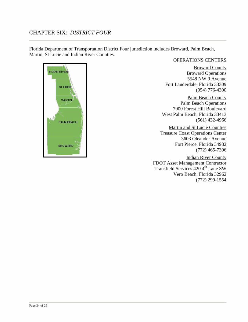
CHAPTER SIX: DISTRICT FOUR
Florida Department of Transportation District Four jurisdiction includes Broward, Palm Beach,
Martin, St Lucie and Indian River Counties.
OPERATIONS CENTERS
Broward County
Broward Operations
5548 NW 9 Avenue
Fort Lauderdale, Florida 33309
(954) 776-4300
Palm Beach County
Palm Beach Operations
7900 Forest Hill Boulevard
West Palm Beach, Florida 33413
(561) 432-4966
Martin and St Lucie Counties
Treasure Coast Operations Center
3603 Oleander Avenue
Fort Pierce, Florida 34982
(772) 465-7396
Indian River County
FDOT Asset Management Contractor
Transfield Services 420 4th
Lane SW
Vero Beach, Florida 32962
(772) 299-1554

Page 25 of 25
DISTRICT OFFICE
3400 West Commercial Boulevard
Fort Lauderdale, Florida 33309
District Permits Office
Christine Bacomo, PE, District Permits Engineer
(954) 777-4377
Stan Williams, Broward County Permits Coordinator
(954) 777-4372
Jerry Dean, Palm Beach County Permits Coordinator
(954) 777-4374
Juan Carlos Rodriguez, Martin, St Lucie, Indian River Counties Permits Coordinator
(954) 777-4437
District Drainage Office
Georgi Celusnek, PE, District Drainage Connection Permits Engineer
(954) 777-4368
Christina (Tina) Borello, EI, Drainage Connection Permits Reviewer
(954) 777-4453
MarQuellus Bennett, EI, Drainage Connection Permits Reviewer
(954) 777-4453
Francis Lewis, PE, District Drainage Engineer
(954) 777-4146