Embed Size (px)
Citation preview
Florida Department of TRANSPORTATION
FDOT Specifications – Asphalt Plant Level 1 Appendix G January 2015 CTQP Update
Contents BASE COURSES .......................................................................................................................... 2
SECTION 234 SUPERPAVE ASPHALT BASE..................................................................... 2 SECTION 283 RECLAIMED ASPHALT PAVEMENT BASE ............................................. 5 SECTION 285 OPTIONAL BASE COURSE .......................................................................... 7 SECTION 287 ASPHALT TREATED PERMEABLE BASE .............................................. 10
BITUMINOUS TREATMENTS, SURFACE COURSES AND CONCRETE PAVEMENT....................................................................................................................................................... 15
SECTION 300 PRIME AND TACK COATS ........................................................................ 15 SECTION 320 HOT MIX ASPHALT - PLANT METHODS AND
EQUIPMENT ............................................................................................................. 20 SECTION 327 MILLING OF EXISTING ASPHALT PAVEMENT ................................... 29 SECTION 330 HOT MIX Asphalt - GENERAL CONSTRUCTION
REQUIREMENTS ...................................................................................................... 33 SECTION 334 SUPERPAVE ASPHALT CONCRETE ........................................................ 45 SECTION 336 ASPHALT RUBBER BINDER ..................................................................... 63 SECTION 337 ASPHALT CONCRETE FRICTION COURSES ......................................... 66 SECTION 338 VALUE ADDED ASPHALT PAVEMENT ................................................. 76 SECTION 339 MISCELLANEOUS ASPHALT PAVEMENT............................................. 84 SECTION 341 ASPHALT RUBBER MEMBRANE INTERLAYER .................................. 86
FLEXIBLE – PAVEMENT MATERIALS .............................................................................. 89
SECTION 916 BITUMINOUS MATERIALS ....................................................................... 89
Asphalt Plant Level 1 Appendix G-1

Florida Department of TRANSPORTATION
2
BASE COURSES SECTION 234
SUPERPAVE ASPHALT BASE
234-1 Description.Construct a Superpave asphalt concrete base course as defined in these Specifications.
Base course mixes are designated as Type B-12.5. The Contractor may use a Type SP-12.5 mixture, (Traffic Level B or C) in lieu of a Type B-12.5. The Contractor may substitute a SP 12.5Traffic Level D or E mixtures in lieu of Type B-12.5 mixtures, not to exceed 500 tons for a project, at no extra cost to the Department, if approved by the Engineer.
Obtain Superpave asphalt base from a plant that is currently on the Department’s Production Facility Listing. Producers seeking inclusion on the list shall meet the requirements of Section 105.
234-2 Materials.234-2.1 General: Use materials that conform to the requirements of Division III. Specific
references are as follows: Superpave PG Asphalt Binder ...........................Section 916 Coarse Aggregate, Stone, Slag or Crushed Gravel ...................................................Section 901 Fine Aggregate ....................................................Section 902
234-2.2 Reclaimed Asphalt Pavement (RAP): RAP may be used as a componentmaterial of the asphalt mixture provided the requirements of 334-2.3 are met.
234-3 General Composition of Mixture.234-3.1 General: Compose the asphalt mixture using a combination of aggregate
(coarse, fine or mixtures thereof), mineral filler if required, and asphalt binder material. Size, grade and combine the aggregate fractions to meet the grading and physical properties of the mix design. Aggregates from various sources may be combined.
234-3.2 Mix Design: Unless otherwise specified, design the mix such that allrequirements for a Type SP-12.5, Traffic Level B or C mixture as specified in Section 334 are met.
234-3.2.1 Gradation Classification: Use a fine mix as defined in 334-3.2.2.1.234-3.2.2 Aggregate Consensus Properties: Meet the aggregate consensus
properties at design as specified in 334-3.2.3. Meet the criteria specified for a depth of top of pavement layer from surface of greater than 4 inches.
234-3.2.3 Mix Design Revisions: Meet the requirements of 334-3.3.
234-4 Contractor’s Process Control.Meet the requirements of 320-2, 330-2 and 334-4.
Asphalt Plant Level 1 Appendix G-2
Florida Department of TRANSPORTATION
3
234-5 Acceptance of the Mixture.The mixture will be accepted in accordance with the requirements of 334-5. Use the
permissible variations from longitudinal and transverse grades as specified in 200-7.
234-6 Plant, Methods and Equipment.Meet requirements of Section 320, with the following modifications: 234-6.1 Paving Equipment: A motor grader may be used to spread the first course of
multiple course bases when the subgrade will not support the use of a mechanical spreader. The Engineer will not require mechanical spreading and finishing equipment for the construction of base widening strips less than 6 feet in width.
234-6.2 Compaction Equipment: In areas where standard rollers cannot beaccommodated, vibratory rollers supplemented with trucks, motor graders, or other compaction equipment approved by the Engineer may be used.
234-7 Construction Requirements.234-7.1 General: Meet the general construction requirements of Section 330, with the
following modifications: 234-7.1.1 Temperature Limitations: Spread the mixture only when the air
temperature is at least 40ºF. Do not place the material on frozen subgrade. 234-7.1.2 Tack Coat: Unless otherwise authorized by the Engineer, apply a tack
coat between successive layers of base material. 234-7.1.3 Thickness of Layers: Construct each course in layers not to exceed
3 inches compacted thickness.
234-8 Thickness Requirements.234-8.1 General: The total thickness of the Type B asphalt layers will be the plan
thickness as shown in the Contract Documents. Before paving, propose a thickness for each individual layer meeting the requirements of this specification, which when combined with other layers (as applicable) will equal the plan thickness. For construction purposes, the plan thickness and individual layer thickness will be converted to spread rate based on the maximum specific gravity of the asphalt mix being used, as well as the minimum density level, as shown in the following equation:
Spread rate (lbs. per square yard) = t x Gmm x 43.3 Where: t = Thickness (in.) (Plan thickness or individual layer thickness)
Gmm = Maximum specific gravity from the verified mix design The weight of the mixture shall be determined as provided in 320-3.2. For target
purposes only, spread rate calculations should be rounded to the nearest whole number. 234-8.2 Spread Rate Tolerance: Control the average spread rate on a daily basis to
within plus or minus 5% of the target spread rate for the individual layers established by the Engineer. When the average daily spread rate is outside this tolerance from the target, adjust the spread rate to the required value established by the Engineer. The Engineer will periodically verify the spread rate at the job site during the paving operation.
234-8.3 Allowable Deficiencies: The Engineer will allow a maximum deficiency fromthe specified spread rate for the total thickness as follows:
Asphalt Plant Level 1 Appendix G-3
Florida Department of TRANSPORTATION
4
1. For pavement of a specified thickness of 2-1/2 inches or more: 50 pounds persquare yard.
2. For pavement of a specified thickness of less than 2-1/2 inches: 25 pounds persquare yard.
234-8.4 Pavement Exceeding Allowable Deficiency in Spread Rate: Where thedeficiency in spread rate for the total thickness is: (1) in excess of 50 pounds per square yard for pavements with a specified thickness of 2-1/2 inches or more, or (2) in excess of 25 pounds per square yard for pavements with a specified thickness of less than 2-1/2 inches, the Engineer may require removal and replacement at no cost or may require a correction as specified in 234-8.5. The Engineer may require the Contractor to core the pavement for thickness in order to determine the area of pavement with deficient thickness.
As an exception to the above, the Contractor may leave pavement outside the main roadway in place without compensation when the Engineer allows, even though the deficiency exceeds the tolerance as specified above.
The Department will not compensate the Contractor for any pavement removed or for the work of removing such pavement.
234-8.5 Correcting Deficiency by Adding New Surface Material: In the event the totalthickness as determined by the spread rate is excessively deficient as defined above and if approved by the Engineer for each particular location, correct the deficient thickness by adding new surface material and compacting it using a rolling pattern as approved by the Engineer. The Engineer will determine the area to be corrected and the thickness of new material added. Perform all overlaying and compacting at no expense to the Department.
234-9 Method of Measurement.The quantity to be paid for will be the plan quantity. For each pay item, the pay area will
be adjusted based upon the following formula: Pay Area = Surface Area (actual tonnage placed/adjusted plan quantity tonnage). Where: The adjusted plan quantity tonnage is calculated by multiplying the plan
quantity square yards (including any Engineer approved quantity revisions ) times the spread rate as defined in 234-8.1 and dividing by 2,000 pound./ton, except the pay item’s tonnage-weighted average Gmm is used instead of the design Gmm as defined in 234-8.1.
The pay area shall not exceed 105% of the designed surface area. Prepare a Certification of Quantities, using the Department’s current approved form, for
the certified Superpave asphalt base pay item. Submit this certification to the Engineer no later than Twelve O’clock noon Monday after the estimate cut-off or as directed by the Engineer, based on the quantity of asphalt produced and accepted on the Contract. The certification must include the Contract Number, FPID Number, Certification Number, Certification Date, period represented by Certification, and the tons produced for each asphalt pay item.
234-10 Basis of Payment.Prices and payments will be full compensation for all work specified in this Section,
including the applicable requirements of Sections 320, 330 and 334. The bid price for the asphalt mix will include the cost of the liquid asphalt binder or the asphalt recycling agent and the tack coat application as directed in 300-8. For the calculation of unit price adjustments of bituminous
Asphalt Plant Level 1 Appendix G-4
Florida Department of TRANSPORTATION
5
material specified in 9-2.1.1, the average asphalt binder content of the base mixes to be used in these calculations is set at 6.25%.
Payment will be made under: Item No. 285- 7- Optional Base - per square yard.
SECTION 283 RECLAIMED ASPHALT PAVEMENT BASE
283-1 Description.Construct a base course composed of reclaimed asphalt pavement (RAP) material. Use
RAP material as a base course only on non-limited access paved shoulders, shared use paths, or other non-traffic bearing applications.
283-2 Materials.Obtain the RAP material by either milling or crushing an existing asphalt pavement. Use
material so that at least 97% (by weight) pass a 3-1/2 inch sieve and is graded uniformly down to dust.
When the RAP material is from a Department project and the composition of existing pavement is known, the Engineer may approve material on the basis of the composition. When the composition of obtained RAP is not known, the following procedure will be used for approval:
(1) Conduct a minimum of six extraction gradation analyses of the RAP material.Take samples at random locations in the stockpile. The average asphalt cement content of the six stockpile samples must be 4% or greater with no individual result below 3-1/2%.
(2) Request the Engineer to make a visual inspection of the stockpile of RAPmaterial. Based on this visual inspection of the stockpiled material and the results of the Contractor’s extraction gradation analyses, the Engineer will determine the suitability of the materials.
(3) The Engineer may require crushing of stockpiled material to meet thegradation criterion. Perform all crushing before the material is placed.
283-3 Spreading RAP Material.283-3.1 Method of Spreading: Spread the RAP with a blade or device which strikes off
the material uniformly to laying thickness and produces an even distribution of the RAP. The Contractor may also place the RAP material directly from the milling machine into the trench by a conveyor. When placing the RAP material by conveyor directly from the milling machine, obtain the Engineer’s approval of the milling process.
283-3.2 Number of Courses: When the specified compacted thickness of the base isgreater than 6 inches, construct the base in two courses. Place the first course to a thickness of
Asphalt Plant Level 1 Appendix G-5
Florida Department of TRANSPORTATION
6
approximately one half the total thickness of the finished base, or sufficient additional thickness to bear the weight of construction equipment without disturbing the subgrade.
Except as might be permitted by the Engineer for special cases, conduct all RAP base construction operations for shoulders before placing the final pavement on the adjacent traveled roadway.
283-4 Compacting and Finishing Base.283-4.1 General: Meet the requirements of 200-6.1:
283-4.1.1 Single-Course Base: Construct as specified in 200-6.1.1.283-4.1.2 Multiple-Course Base: Construct as specified in 200-6.1.2.
283-4.2 Moisture Content: Meet the requirements of 200-6.2.283-4.3 Density Requirements: Compact the material to a density of not less than
95% of maximum density as determined by FM 1-T 180. Where the width of the base construction is not sufficient to permit use of standard base compaction equipment, perform compaction using vibratory compactors, trench rollers, or other special equipment which will provide the density requirements specified herein.
283-4.4 Density Tests: Meet the requirements of 200-7 with the exception of 200-7.2.1.Within the entire limits of the width and depth of the base, obtain a minimum density in any LOT of 95% of the maximum density as determined by FM 1-T 180.
283-4.5 Thickness Requirements: Meets the thickness requirements of 285-6.
283-5 Testing Surface.Test the surface in accordance with the requirements of 200--.4.
283-6 Priming and Maintaining.283-6.1 Priming: Apply the prime coat only when the base meets the specified density
requirements and the moisture content in the top half of the base is within 2% of optimum. At the time of priming, ensure that the base is firm, unyielding, and in such condition that no undue distortion will occur. The Engineer will not allow priming if the surface is dry, dusty, or sloughing.
283-6.2 Maintaining: Meet the requirements of 200-8.2.
Asphalt Plant Level 1 Appendix G-6
Florida Department of TRANSPORTATION
7
SECTION 285 OPTIONAL BASE COURSE
285-1 Description. Construct a base course composed of one of the optional materials shown on the typical cross-sections.
285-2 Materials. Meet the material requirements as specified in the Section covering the particular type of base to be constructed.
Graded Aggregate ...............................................Section 204 Asphalt ................................................................Section 234 Limerock .............................................................Section 911 Shell Base............................................................Section 911 Shell-Rock...........................................................Section 911 Cemented Coquina ..............................................Section 911 Recycled Concrete Aggregate (RCA)* ...............Section 911 *Do not use on interstate roadways.
285-3 Selection of Base Option. The Plans will include typical cross-sections indicating the various types of base construction (material and thickness) allowable. Select one base option as allowed for each typical cross-section shown in the Plans. Only one base option is permitted for each typical cross-section. Notify the Engineer in writing of the base option selected for each typical cross-section at least 45 calendar days prior to beginning placement of base material.
285-4 Construction Requirements. Construct the base in accordance with the Section covering the particular type of base to be constructed.
Graded Aggregate ...............................................Section 204 Asphalt ................................................................Section 234 Limerock .............................................................Section 200 Shell Base............................................................Section 200 Shell Rock ...........................................................Section 200 Cemented Coquina ..............................................Section 200 Recycled Concrete Aggregate (RCA)* ...............Section 200 *Do not use on interstate roadways.
285-5 Variation in Earthwork Quantities. The Plans will identify the optional materials used by the Department for determining the earthwork quantities (Roadway Excavation, Borrow Excavation, Subsoil Excavation, Subsoil Earthwork, or Embankment). The Department will not revise the quantities, for those items
Asphalt Plant Level 1 Appendix G-7
Florida Department of TRANSPORTATION
8
having final pay based on plan quantity, to reflect any volumetric change caused by the Contractor’s selection of a different optional material.
285-6 Thickness Requirements.285-6.1 Measurements: For non-asphalt bases, meet the requirements of 200-7.3.1.2.
For subbases, meet the thickness requirements of 290-4. The Engineer will determine the thickness of asphalt base courses in accordance
with 234-8.1. 285-6.2 Correction of Deficient Areas: For non-asphalt bases, correct all areas of the
completed base having a deficiency in thickness in excess of 1/2 inch by scarifying and adding additional base material. As an exception, if authorized by the Engineer, such areas may be left in place without correction and with no payment.
For asphalt bases, correct all areas of deficient thickness in accordance with 234-8.
285-7 Calculation of Average Thickness of Base.For bases that are not mixed in place, the Engineer will determine the average thickness
from the measurements specified in 285-6.1, calculated as follows; (a) When the measured thickness is more than 1/2 inch greater than the design
thickness shown on the typical cross-section in the Plans, it will be considered as the design thickness plus 1/2 inch.
(b) Average thickness will be calculated per typical cross-section for the entire jobas a unit.
(c) Any areas of base left in place with no payment will not be included in thecalculations.
(d) Where it is not possible through borings to distinguish the base materials fromthe underlying materials, the thickness of the base used in the measurement will be the design thickness.
(e) For Superpave asphalt base course, the average spread rate of each courseshall be constructed in compliance with 234-8.
285-8 Method of Measurement.The quantity to be paid for will be the plan quantity area in square yards, omitting any
areas where under-thickness is in excess of the allowable tolerance as specified in 285-6. The pay area will be the surface area, determined as provided above, adjusted in accordance with the following formula:
)Thickness Plan
7-285 per Thickness Average Calculated( Area Surface= AreaPay
The pay area shall not exceed 105% of the surface area. There will be no adjustment of the pay area on the basis of thickness for base courses
constructed utilizing mixed-in-place operations. For Superpave asphalt base course, the quantity to be paid for will be the plan quantity.
Asphalt Plant Level 1 Appendix G-8

Florida Department of TRANSPORTATION
9
285-9 Basis of Payment.Price and payment will be full compensation for all work specified in this Section,
including tack coat between base layers, prime coat, cover material for prime coat, bituminous material used in bituminous plant mix, and cement used in soil-cement.
Where the Plans include a typical cross-section which requires the construction of an asphalt base only, price adjustments for bituminous material provided for in 9-2.1.2 will apply to that typical cross-section. For typical cross-sections which permit the use of asphalt or other materials for construction of an optional base, price adjustments for bituminous material provided for in 9-2.1.2 will not apply.
Payment will be made under: Item No. 285- 7- Optional Base - per square yard.
Asphalt Plant Level 1 Appendix G-9
Florida Department of TRANSPORTATION
10
SECTION 287 ASPHALT TREATED PERMEABLE BASE
287-1 Description. Construct asphalt treated permeable base (ATPB) and outlet pipe for use under concrete pavement, in accordance with the details shown in the Plans and the Design Standards, Index No. 287. Meet the plant and equipment requirements of Section 320 and the general construction requirements of Section 330, except as noted below.
287-2 Materials. Meet the following requirements:
Coarse Aggregate, Stone, Slag, or Crushed Gravel Grade No. 57 or 67..................................Section 901
Superpave PG Asphalt Binder (PG 67-22) (1) .............. 916-1 Hydrated Lime (2) ..................... AASHTO M-303-89 Type 1 Polyvinyl-Chloride Pipe (3) .................................Section 948 Polyethylene Pipe (3) ...........................................Section 948 Geosynthetic Material .........................................Section 985
(1) Use PG 67-22 in the ATPB containing 0.75% heat-stable anti-strip additive (by weight of asphalt) from an approved source. Introduce and mix the anti-strip additive at the terminal. (2) For mixtures containing granite, add hydrated lime at a dosage rate of 1.0% by weight of the total dry aggregate in lieu of adding 0.75% anti-strip additive. Provide certified test results for each shipment of hydrated lime indicating compliance with the specifications. In addition, meet the requirements of 337-9.2 and 337-9.3. (3) Use either polyvinyl chloride pipe or polyethylene pipe, unless otherwise specified in the Contract Documents.
287-3 Composition of Mixture. 287-3.1 General: Use ATPB composed of a combination of coarse aggregate and asphalt cement. Use a mix design verified by the Engineer. 287-3.2 Mix Design: Submit a proposed mix design along with representative samples of all component materials to the Engineer, at least two weeks before the scheduled start of production. Establish the design asphalt content within the range of 2.0 - 4.0%, by weight of total mixture. During the mix design process, the Engineer may adjust the asphalt content within the 2.0 - 4.0% range. The Engineer may increase or decrease the specified asphalt content during production of the mix after testing and visual inspection. Ensure that a minimum of 95% of the aggregate is coated. There will be no separate payment for the bituminous material in the mix. Establish the mix temperature within the range of 230ºF to 250ºF, or as approved by the Engineer.
Asphalt Plant Level 1 Appendix G-10
Florida Department of TRANSPORTATION
11
287-4 Control of Quality. Provide the necessary control of the ATPB and construction in accordance with the applicable provisions of 320-2 and 330-2.
287-5 Acceptance of the Mixture at the Plant. The ATPB mixture will be accepted at the plant with respect to 334-5.1 with the following exceptions: 1. The mixture will be accepted with respect to gradation (P-1/2 if No. 57 stone is used and P-3/8 if No. 67 stone is used) and asphalt binder content (Pb) only. 2. Testing in accordance with AASHTO T312-12 and FM 1-T209 (and conditioning of the mix prior to testing) will not be required as part of 334-5.1.1.1. 3. The standard LOT size will be, 2,000 tons, with each LOT subdivided into four equal sublots of 500 tons each. 4. Initial production requirements of 334-5.1.3 do not apply. 5. The Between-Laboratory Precision Values described in Table 334-6 are modified to include (P-1/2 and P-3/8) with a maximum difference per FM 1-T030 (Figure 2). 6. Table 334-5 (Master Production Range) is replaced by Table 287-1.
Table 287-1 ATPB Master Production Range
Characteristic Tolerance (1) Asphalt Binder Content (%) Target ± 0.60
Passing 1/2 inch Sieve (%) if using No. 57 stone Target ± 12.00
Passing 3/8 inch Sieve (%) if using No. 67 stone Target ± 12.00
(1) Tolerances for sample size of n = 1 from the verified mix design 287-5.1 Individual Test Tolerances for ATPB Production: In the event that an individual Quality Control test result of a sublot for gradation (P-1/2 if No. 57 stone is used and P-
3/8 if No. 67 stone is used), or asphalt binder content does not meet the requirements of Table 287-1, take steps to correct the situation and actions taken shall be reported to the Engineer. In the event that two consecutive individual Quality Control test results for gradation (P-1/2 if No. 57 stone is used and P-3/8 if No. 67 stone is used) or asphalt binder content do not meet the requirements of Table 287-1, the LOT will be automatically terminated and production of the mixture stopped until the problem is adequately resolved (to the satisfaction of the Engineer), unless it can be demonstrated to the satisfaction of the Engineer that the problem can immediately be (or already has been) resolved. Evaluate any material represented by the failing test result in accordance with 334-5.1.9.
287-6 Acceptance of the Mixture at the Roadway. Acceptance of the Contractor’s methods of placement and compaction will be based upon the completion of a 500 foot test section, (initially and at other times as determined by the
Asphalt Plant Level 1 Appendix G-11
Florida Department of TRANSPORTATION
12
Engineer), acceptable to the Engineer, prior to further placement. In the event that the placement/compaction method deviates from the approved method, cease placement of the mix until the problem is adequately resolved to the satisfaction of the Engineer.
287-7 Temperature and Storage Limitations.Place the ATPB material when the atmospheric temperature is above 50ºF and rising. Do
not use ATPB material that was mixed more than two hours prior to placement.
287-8 Construction Requirements.287-8.1 Placement: Ensure that the structural course on which ATPB is to be placed
conforms to the compaction and elevation tolerances specified in the Contract Documents and is free of loose or extraneous material. Fill any area of the structural course which is lower than the grade established by the Plans with structural course material, at no additional cost to the Department.
Place and compact ATPB in one lift, with a compacted thickness of plus 4 inches or minus 1/2 inch (except the trench which includes the subdrainage pipe), in accordance with these Specifications, lines, grades, dimensions and notes as shown in the Plans.
Place and compact ATPB material around the subdrainage pipe for the full width of the trench, in layers not exceeding 8 inches (loose measure). Do not displace or damage the subdrainage pipe or filter fabric.
Remove and replace all ATPB material which is greater than 1/2 inch below the grade shown in the Plans or, in the opinion of the Engineer, is damaged or contaminated, at no additional cost to the Department.
287-8.2 Compaction: Compact the ATPB by one of the following methods:1. A steel-wheeled, tandem roller which will produce an operating weight of not
more than 140 PLI of drum width. 2. A steel-wheeled tandem roller weighing from 8 to 12 tons.Compact the ATPB material (in the static mode only) as approved by the
Engineer. Begin compaction as soon as the surface temperature has cooled to 190°F, or as approved by the Engineer and complete compaction before the surface temperature has cooled to 100°F. If necessary, cool the ATPB material with water.
287-8.3 Surface Requirements: Ensure that the finished surface of the ATPB does notvary more than plus or minus1/2 inch from the grade shown in the Plans.
The Engineer may approve removal of high spots to within specified tolerance by a method which does not produce contaminating fines. Remove and replace ATPB material that is outside the established tolerance, at no additional cost to the Department. Grinding or milling will not be permitted.
287-9 Subdrainage Pipe and Geosynthetic Material.Place the subdrainage pipe and geosynthetic material (filter fabric) in accordance with the
Plans and Design Standards, Index No. 287.
Asphalt Plant Level 1 Appendix G-12
Florida Department of TRANSPORTATION
13
287-10 Outlet Pipe.Install outlet fittings and pipes concurrent with subdrainage pipe to provide positive
gravity drainage and eliminate soil intrusion. The Engineer will restrict installation of additional sections of ATPB, until appropriate outlets are installed.
Ensure that all fittings and materials are designed and installed to eliminate soil intrusion into the system.
Connect the open end of the outlet pipe into either an existing drainage structure, existing ditch pavement or terminate with a concrete apron.
Do not block the drainage system at any time. Ensure that at the time of inspection and project acceptance, all outlet pipes and concrete aprons are clear of earth material, vegetation, and other debris.
287-11 Compensation.Meet the requirements of 334-8 with the following exceptions:
1. Pay factors will be calculated for asphalt binder content and the percentagespassing the 1/2 inch and the 3/8 inch sieves only.
2. Table 287-2 replaces Table 334-6.3. Table 287-3 replaces Table 334-7.4. The Composite Pay Factor in 334-8.3 is replaced with the following:
CPF = [(0.25 x PF 1/2 inch or 3/8 inch) + (0.75 x PF AC)] Note: Use the PF for the 1/2 inch sieve if No. 57 stone is used in the
mixture or use the PF for the 3/8 inch sieve if No. 67 stone is used in the mixture.
Table 287-2 Small Quantity Pay Table for ATPB
Pay Factor 1-Test Deviation 2-Test Average DeviationAsphalt Binder Content (%)
1.00 0.00-0.50 0.00-0.35 0.90 0.51-0.60 0.36-0.42 0.80 >0.60 >0.42
1/2 inch Sieve (%) if using No. 57 stone 1.00 0.00-11.00 0.00-7.78 0.90 11.01-12.00 7.79-8.49 0.80 >12.00 >8.49
3/8 inch Sieve (%) if using No. 67 stone 1.00 0.00- 11.00 0.00- 7.78 0.90 11.01-12.00 7.79-8.49 0.80 >12.00 >8.49
Asphalt Plant Level 1 Appendix G-13
Florida Department of TRANSPORTATION
14
Table 287-3 Specification Limits for ATPB
Quality Characteristic Specification Limits Asphalt Binder Content (%) Target ± 0.45
Passing 1/2 inch sieve (%) if using No. 57 stone Target ± 10.00
Passing 3/8 inch sieve (%) if using No. 67 stone Target ± 10.00
287-12 Low Quality Material.Meet the requirements of 334-5.1.9. For ATPB, use the Master Production Range defined
in Table 287-1 in lieu of Table 334-5.
287-13 Method of Measurement.287-13.1 Asphalt Treated Permeable Base: The quantity of ATPB to be paid for will
be the plan quantity, in cubic yards, completed and accepted, subject to 9-3.2. No allowance will be made for ATPB placed outside plan dimensions, unless otherwise ordered by the Engineer.
287-13.2 Outlet Pipe: The quantity of outlet pipe to be paid for will be the length, infeet, measured in place along the centerline and gradient of the pipe, completed and accepted.
287-14 Basis of Payment.287-14.1 Asphalt Permeable Base: Price and payment will be full compensation for
work specified in this Section, including furnishing all labor, materials (including the ATPB material, geosynthetic material, and subdrainage pipe), tools, equipment, and incidentals, necessary to complete the work.
287-14.2 Outlet Pipe: Price and payment will be full compensation for work specified inthis Section, including removal of existing shoulder pavement, trench excavation, pipe and fittings, standard aprons, galvanized hardware cloth (rodent screens), grouting around and stubbing into existing or proposed drainage structures or ditch pavement; restoration of ditch pavement, sod and other areas disturbed by the Contractor, backfill in place, disposal of excess materials and incidentals, necessary to complete the work.
287-14.3 Payment Items: Payment will be made under:Item No. 287- 1 Asphalt Treated Permeable Base - per cubic yard. Item No. 446- 71-1 Edgedrain Outlet Pipe - per foot.
Asphalt Plant Level 1 Appendix G-14

Florida Department of TRANSPORTATION
15
BITUMINOUS TREATMENTS, SURFACE COURSES AND CONCRETE PAVEMENT
SECTION 300 PRIME AND TACK COATS
300-1 Description. Apply bituminous prime coats on previously prepared bases, and apply bituminous tack coats on previously prepared bases and on existing pavement surfaces.
300-2 Materials. 300-2.1 Prime Coat: For prime coat, use a product listed on the Department’s Approved Product List (APL), meeting the requirements of 916-2, or other types and grades of bituminous material if specified in the Contract Documents. Where prime coats are to be diluted, certify that the dilution was done in accordance with the specific dilution requirements for each product and for each load of material used. The Contractor may select any of the approved prime coats unless the Contract Documents indicate the use of a specific material. The Engineer may allow types and grades of bituminous material other than those specified above if the Contractor can show the alternate material will properly perform the function of prime coat material. 300-2.2 Cover Material for Prime Coat: Uniformly cover the primed base by a light application of cover material. However, if using EPR-1 prime material, the Engineer may waive the cover material requirement if the primed base is not exposed to general traffic and construction traffic does not mar the prime coat so as to expose the base. The Contractor may use either sand or screenings for the cover material. For the sand, meet the requirements as specified in 902-2 or 902-6, and for the screenings, meet the requirements as specified in 902-5. If the primed base course will be exposed to general traffic, apply a cover material that has been coated with 2 to 4% asphalt cement. Apply the asphalt coated material at approximately 10 lb/yd2. Roll the entire surface of asphalt coated prime material with a traffic roller as required to produce a reasonably dense mat. 300-2.3 Tack Coat: Unless the Contract Documents call for a specific type or grade of tack coat, use PG 52-28 meeting the requirements of 916-1, heated to a temperature of 250 to 300ºF or use an undiluted emulsion listed on the APL, meeting the requirements of 916-2. Heat the emulsion to the temperature recommended by the tack coat manufacturer. For night paving, use PG 52-28 tack coat. The Engineer may approve an emulsified tack coat for night paving if the Contractor demonstrates, at the time of use, that the emulsion will break and not affect the progress of the paving operation. 300-3 Equipment. 300-3.1 Pressure Distributor: Provide a pressure distributor that is equipped with pneumatic tires having a sufficient width of rubber in contact with the road surface to avoid breaking the bond or forming a rut in the surface. Ensure that the distance between the centers of openings of the outside nozzles of the spray bar is equal to the width of the application required,
Asphalt Plant Level 1 Appendix G-15

Florida Department of TRANSPORTATION
16
within an allowable variation of 2 inches. Ensure that the outside nozzle at each end of the spray bar has an area of opening not less than 25% or more than 75% in excess of the other nozzles. Ensure that all other nozzles have uniform openings. When the application covers less than the full width, the Contractor may allow the normal opening of the end nozzle at the junction line to remain the same as those of the interior nozzles. 300-3.2 Sampling Device: Equip all pressure distributors and transport tanks with an approved spigot-type sampling device. 300-3.3 Temperature Sensing Device: Equip all pressure distributors and transport tanks with an approved dial type thermometer. Use a thermometer with a temperature range from 50 to 500ºF with maximum 25ºF increments with a minimum dial diameter of 2 inches. Locate the thermometer near the midpoint in length and within the middle third of the height of the tank, or as specified by the manufacturer (if in a safe and easily accessible location). Enclose the thermometer in a well with a protective window or by other means as necessary to keep the instrument clean and in the proper working condition.
300-4 Contractor’s Quality Control. Provide the necessary quality control of the prime and tack coats and application in accordance with the Contract requirements. Provide in the Quality Control Plan, procedures for monitoring and controlling of rate of application. If the rate of application varies by more than 5% from the rate set by the Engineer or varies beyond the range established in 300-7or 300-8, immediately make all corrections necessary to bring the spread rate into the acceptable range. The Engineer may take additional measurements at any time. The Engineer will randomly check the Contractor’s measurement to verify the spread rate.
300-5 Cleaning Base and Protection of Adjacent Work. Before applying any bituminous material, remove all loose material, dust, dirt, caked clay and other foreign material which might prevent proper bond with the existing surface for the full width of the application. Take particular care in cleaning the outer edges of the strip to be treated, to ensure that the prime or tack coat will adhere. When applying the prime or tack coat adjacent to curb and gutter, valley gutter, or any other concrete surfaces, cover such concrete surfaces, except where they are to be covered with a bituminous wearing course, with heavy paper or otherwise protect them as approved by the Engineer, while applying the prime or tack coat. Remove any bituminous material deposited on such concrete surfaces.
300-6 Weather Limitations. Do not apply prime and tack coats when the air temperature in the shade and away from artificial heat is less than 40ºF at the location where the application is to be made or when weather conditions or the surface conditions are otherwise unfavorable.
300-7 Application of Prime Coat. 300-7.1 General: Clean the surface to be primed and ensure that the moisture content of the base does not exceed the optimum moisture. Heat the prime coat material to the temperature
Asphalt Plant Level 1 Appendix G-16
Florida Department of TRANSPORTATION
17
recommended by the prime coat manufacturer. Apply the material with a pressure distributor. Determine the application amount based on the character of the surface. Use an amount sufficient to coat the surface thoroughly and uniformly with no excess. 300-7.2 Rate of Application: 300-7.2.1 Limerock, Limerock Stabilized, and Local Rock Bases: For these bases, use a rate of application that is not less than 0.10 gal/yd2, unless a lower rate is directed by the Engineer. Determine the application rate at the beginning of each day’s production, and as needed to control the operation, a minimum of twice per day. 300-7.2.2 Sand-Clay, Shell and Shell Stabilized Bases: For these bases, use a rate of application that is not less than 0.15 gal/yd2, unless a lower rate is directed by the Engineer. Determine the application rate at the beginning of each day’s production, and as needed to control the operation, a minimum of twice per day. 300-7.3 Sprinkling: If so required by the Engineer, lightly sprinkle the base with water and roll it with a traffic roller in advance of the application of the prime coat. 300-7.4 Partial Width of Application: If traffic conditions warrant, the Engineer may require that the application be made on only 1/2 the width of the base at one time, in which case use positive means to secure the correct amount of bituminous material at the joint.
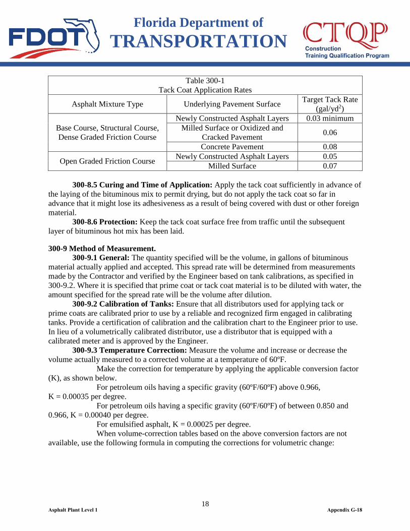
300-8 Application of Tack Coat. 300-8.1 General: Where the Engineer requires a tack coat prior to laying a bituminous surface, apply the tack coat as specified herein below. 300-8.2 Where Required: Place a tack coat on all asphalt layers prior to constructing the next course. In general, the Engineer will not require a tack coat on primed bases except in areas that have become excessively dirty and cannot be cleaned, or in areas where the prime has cured to the extent that it has lost all bonding effect. 300-8.3 Method of Application: Apply the tack coat with a pressure distributor except that on small jobs, if approved by the Engineer, apply it by other mechanical devices or by hand methods. Heat the bituminous material to a suitable temperature as designated by the Engineer, and apply it in a thin, uniform layer. 300-8.4 Rate of Application: Use a rate of application as defined in Table 300-1. Control the rate of application to be within plus or minus 0.01 gallon per square yard of the target application rate. The target application rate may be adjusted by the Engineer to meet specific field conditions. Determine and record the rate of application a minimum of twice per day, once at the beginning of each day’s production and again as needed to control the operation. When using PG 52-28, multiply the target rate of application by 0.6.
Asphalt Plant Level 1 Appendix G-17
Florida Department of TRANSPORTATION
18
Table 300-1 Tack Coat Application Rates
Asphalt Mixture Type Underlying Pavement Surface Target Tack Rate (gal/yd2)
Base Course, Structural Course, Dense Graded Friction Course
Newly Constructed Asphalt Layers 0.03 minimum Milled Surface or Oxidized and
Cracked Pavement 0.06
Concrete Pavement 0.08
Open Graded Friction Course Newly Constructed Asphalt Layers 0.05 Milled Surface 0.07
300-8.5 Curing and Time of Application: Apply the tack coat sufficiently in advance of the laying of the bituminous mix to permit drying, but do not apply the tack coat so far in advance that it might lose its adhesiveness as a result of being covered with dust or other foreign material. 300-8.6 Protection: Keep the tack coat surface free from traffic until the subsequent layer of bituminous hot mix has been laid.
300-9 Method of Measurement. 300-9.1 General: The quantity specified will be the volume, in gallons of bituminous material actually applied and accepted. This spread rate will be determined from measurements made by the Contractor and verified by the Engineer based on tank calibrations, as specified in 300-9.2. Where it is specified that prime coat or tack coat material is to be diluted with water, the amount specified for the spread rate will be the volume after dilution. 300-9.2 Calibration of Tanks: Ensure that all distributors used for applying tack or prime coats are calibrated prior to use by a reliable and recognized firm engaged in calibrating tanks. Provide a certification of calibration and the calibration chart to the Engineer prior to use. In lieu of a volumetrically calibrated distributor, use a distributor that is equipped with a calibrated meter and is approved by the Engineer. 300-9.3 Temperature Correction: Measure the volume and increase or decrease the volume actually measured to a corrected volume at a temperature of 60ºF. Make the correction for temperature by applying the applicable conversion factor (K), as shown below. For petroleum oils having a specific gravity (60ºF/60ºF) above 0.966, K = 0.00035 per degree. For petroleum oils having a specific gravity (60ºF/60ºF) of between 0.850 and 0.966, K = 0.00040 per degree. For emulsified asphalt, K = 0.00025 per degree. When volume-correction tables based on the above conversion factors are not available, use the following formula in computing the corrections for volumetric change:
Asphalt Plant Level 1 Appendix G-18

Florida Department of TRANSPORTATION
19
1+60)-(T KV = V
1
Where: V= Volume of the bituminous material at 60ºF (pay volume). V1= Volume of bituminous material as measured. K= Correction factor (Coefficient of Expansion). T= Temperature (in ºF), of the bituminous material when measured.
300-10 Basis of Payment. There is no direct payment for the work specified in this Section, it is incidental to, and is to be included in the other items of related work.
Asphalt Plant Level 1 Appendix G-19
Florida Department of TRANSPORTATION
20
SECTION 320 HOT MIX ASPHALT -
PLANT METHODS AND EQUIPMENT
320-1 General. This Section specifies the basic equipment and operational requirements for hot mix asphalt (including warm mix asphalt) production facilities used in the construction of asphalt pavements and bases. Establish and maintain a quality control system that provides assurance that all materials and products submitted for acceptance meet Contract requirements.
320-2 Quality Control (QC) Requirements. 320-2.1 Minimum Producer QC Requirements: Perform as a minimum the following activities: 1. Stockpiles: a. Assure materials are placed in the correct stockpile; b. Assure good stockpiling techniques; c. Inspect stockpiles for separation, contamination, segregation, and other similar items; d. Properly identify and label each stockpile. 2. Incoming Aggregate: a. Obtain gradations and bulk specific gravity (Gsb) values from aggregate supplier for reference; b. Determine the gradation of all component materials and routinely compare gradations and Gsb values to mix design.
3. Cold Bins: a. Calibrate the cold gate/feeder belt for each material; b. Determine cold gate/feeder belt settings; c. Observe operation of cold feeder for uniformity; d. Verify accuracy of all settings; e. Verify that the correct components are being used, and that all modifiers or additives or both are being incorporated into the mix. 4. Batch Plants: a. Determine percent used and weight to be pulled from each bin to assure compliance with the mix design; b. Check mixing time; c. Check operations of weigh bucket and scales. 5. Drum Mixer Plants: a. Determine aggregate moisture content; b. Calibrate the weigh bridge on the charging conveyor. 6. Control Charts: Maintain QC data and charts (updated daily) for all QC Sampling and Testing and make available upon demand. Provide the following charts: a. All components used to determine the composite pay factor (No. 8 sieve, No. 200 sieve, asphalt binder content, air voids, and density); b. Gradation of incoming aggregate;
Asphalt Plant Level 1 Appendix G-20
Florida Department of TRANSPORTATION
21
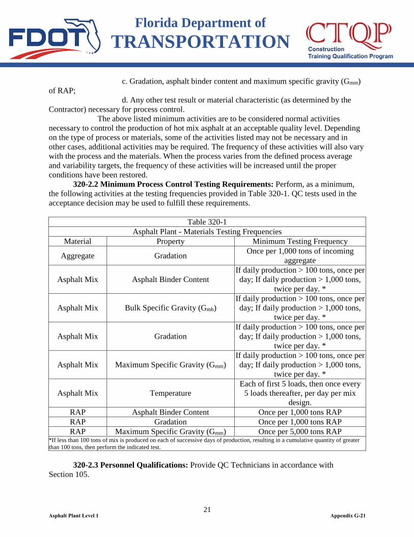
c. Gradation, asphalt binder content and maximum specific gravity (Gmm) of RAP; d. Any other test result or material characteristic (as determined by the Contractor) necessary for process control. The above listed minimum activities are to be considered normal activities necessary to control the production of hot mix asphalt at an acceptable quality level. Depending on the type of process or materials, some of the activities listed may not be necessary and in other cases, additional activities may be required. The frequency of these activities will also vary with the process and the materials. When the process varies from the defined process average and variability targets, the frequency of these activities will be increased until the proper conditions have been restored. 320-2.2 Minimum Process Control Testing Requirements: Perform, as a minimum, the following activities at the testing frequencies provided in Table 320-1. QC tests used in the acceptance decision may be used to fulfill these requirements.
Table 320-1 Asphalt Plant - Materials Testing Frequencies
Material Property Minimum Testing Frequency
Aggregate Gradation Once per 1,000 tons of incoming aggregate
Asphalt Mix Asphalt Binder Content If daily production > 100 tons, once per day; If daily production > 1,000 tons,
twice per day. *
Asphalt Mix Bulk Specific Gravity (Gmb) If daily production > 100 tons, once per day; If daily production > 1,000 tons,
twice per day. *
Asphalt Mix Gradation If daily production > 100 tons, once per day; If daily production > 1,000 tons,
twice per day. *
Asphalt Mix Maximum Specific Gravity (Gmm) If daily production > 100 tons, once per day; If daily production > 1,000 tons,
twice per day. *
Asphalt Mix Temperature Each of first 5 loads, then once every
5 loads thereafter, per day per mix design.
RAP Asphalt Binder Content Once per 1,000 tons RAP RAP Gradation Once per 1,000 tons RAP RAP Maximum Specific Gravity (Gmm) Once per 5,000 tons RAP
*If less than 100 tons of mix is produced on each of successive days of production, resulting in a cumulative quantity of greater than 100 tons, then perform the indicated test. 320-2.3 Personnel Qualifications: Provide QC Technicians in accordance with Section 105.
Asphalt Plant Level 1 Appendix G-21

Florida Department of TRANSPORTATION
22
320-2.4 Hot Mix Asphalt Testing Laboratory Requirements: Furnish a fully equipped asphalt laboratory at the production site. The laboratory must be qualified under the Department’s Laboratory Qualification Program, as described in Section 105. In addition, the laboratory shall meet the following requirements: 1. Area - The effective working area of the laboratory shall be a minimum of 180 square feet, with a layout of which will facilitate multiple tests being run simultaneously by two technicians. This area does not include the space for desks, chairs and file cabinets. Any variations shall be approved by the Engineer. 2. Lighting - The lighting in the lab must be adequate to illuminate all areas of the work. 3. Temperature Control - Equip the lab with heating and air conditioning units that provide a satisfactory working environment. 4. Ventilation - Equip the lab with exhaust fans that will remove all hazardous fumes from within the laboratory in accordance with OSHA requirements. 5. Equipment and Supplies - Furnish the lab with the necessary sampling and testing equipment and supplies for performing contractor QC and Department Verification Sampling and Testing. A detailed list of equipment and supplies required for each test is included in the appropriate FDOT, AASHTO, or ASTM Test Method. In the event testing equipment goes out of service during production, the Contractor may elect to use replacement equipment at another laboratory qualified, as described in Section 105, for up to 72 hours upon notification of the Engineer. 6. Personal Computer - Provide a personal computer capable of running a Microsoft ExcelTM spreadsheet program, along with a printer. 7. Communication - Provide a telephone and fax machine (with a private line) for the use of the testing facility’s QC personnel. In addition, provide an internet connection capable of uploading data to the Department’s database and for e-mail communications.
320-3 Requirements for All Plants. 320-3.1 General: Design, manufacture, coordinate, and operate the asphalt plant in a manner that will consistently produce a mixture within the required tolerances and temperatures specified. 320-3.2 Electronic Weigh Systems: Equip the asphalt plant with an electronic weigh system that: 1) has an automatic printout, 2) is certified every six months by an approved certified scale technician, and 3) meets monthly comparison checks with certified truck scales as specified in 320-3.2.4. Weigh all plant produced hot mix asphalt on the electronic weigh system, regardless of the method of measurement for payment. Include, as a minimum, the following information on the printed delivery ticket: (a) Sequential load number (b) Project number (c) Date (d) Name and location of plant (e) Mix design number (f) Place for hand-recording mix temperature (g) Truck number
Asphalt Plant Level 1 Appendix G-22
Florida Department of TRANSPORTATION
23
(h) Gross, tare, and net tonnage per truck (as applicable) (i) Daily total tonnage of mix for the mix design Print the delivery ticket with an original and at least one copy. Furnish the original to the Engineer at the plant and one copy to the Engineer at the paving site. Utilize any one of the following three electronic weigh systems. 320-3.2.1 Electronic Weigh System on the Truck Scales: Provide an electronic weigh system on all truck scales, which is equipped with an automatic recordation system that is approved by the Engineer. Use scales of the type that directly indicate the total weight of the loaded truck. Use scales meeting the requirements for accuracy, condition, etc., of the Bureau of Weights and Measures of the Florida Department of Agriculture, and re-certify such fact every six months, either by the Bureau of Weights and Measures or by a registered scale technician. 320-3.2.2 Electronic Weigh System on Hoppers Beneath a Surge or Storage Bin: Provide an electronic weigh system on the hopper (hopper scales or load cells) beneath the surge or storage bin, which is equipped with an automatic recordation system approved by the Engineer. 320-3.2.3 Automatic Batch Plants with Printout: For batch plants, provide an approved automatic printer system which will print the individual or cumulative weights of aggregate and liquid asphalt delivered to the pugmill and the total net weight of the asphalt mix measured by hopper scales or load cell type scales. Use the automatic printer system only in conjunction with automatic batching and mixing control systems that have been approved by the Engineer. 320-3.2.4 Monthly Electronic Weigh System Comparison Checks: Check the accuracy of the electronic weighing system at the commencement of production and thereafter at least every 30 days during production by one of the following two methods and maintain a record of the weights in the Scale Check Worksheet. 320-3.2.4.1. Electronic Weigh System on Truck Scales: (a) The Engineer will randomly select a loaded truck of asphalt mix, a loaded aggregate haul truck, or another vehicle type approved by the Engineer and record the truck number and gross weight from the Contractor’s delivery ticket. (b) Weigh the selected truck on a certified truck scale, which is not owned by the Contractor and record the gross weight for the comparison check. If another certified truck scale is not available, the Engineer may permit another set of certified truck scales owned by the Contractor to be used. The Engineer may elect to witness the scale check. (c) The gross weight of the loaded truck as shown on the Contractor’s delivery ticket will be compared to the gross weight of the loaded truck from the other certified truck scale. The maximum permissible deviation is 8 pounds per ton of load, based on the certified truck scale weight. (d) If the distance from the asphalt plant to the nearest certified truck scale is enough for fuel consumption to affect the accuracy of the comparison checks, a fuel adjustment may be calculated by using the truck odometer readings for the distance measurement, and 6.1 miles per gallon for the fuel consumption rate, and 115 ounces per gallon for fuel weight.
Asphalt Plant Level 1 Appendix G-23
Florida Department of TRANSPORTATION
24
(e) During production, when an additional certified truck scale is not available for comparison checks, the Engineer may permit the Contractor to weigh the truck on his certified scales used during production and then weigh it on another certified truck scale, as soon the other scale is available for the comparison checks. In addition to the periodic checks as specified above, check the scales at any time the accuracy of the scales becomes questionable. When such inaccuracy does not appear to be sufficient to seriously affect the weighing operations, the Engineer will allow a period of two calendar days for the Contractor to conduct the required scale check. However, in the event the indicated inaccuracy is sufficient to seriously affect the mixture, the Engineer may require immediate shut-down until the accuracy of the scales has been checked and necessary corrections have been made. Include the cost of all scale checks in the bid price for asphalt concrete, at no additional cost to the Department. 320-3.2.4.2. Electronic Weigh System on Hoppers Beneath a Surge or Storage Bin and Automatic Batch Plants with Printout: (a) The Engineer will randomly select a loaded truck of asphalt mix and record the truck number, and the net weight of the asphalt mix from the Contractor’s delivery ticket. (b) Weigh the selected truck on a certified truck scale, which is not owned by the Contractor and record the gross weight for the comparison check. If another certified truck scale is not available, the Engineer may permit another set of certified truck scales owned by the Contractor to be used. The Engineer may elect to witness the scale check. (c) Deliver the asphalt mix to the project, then weigh the selected empty truck on the same certified truck scales. Record the tare weight of the truck. (d) Compare the net weight of the asphalt mix from the delivery ticket to the calculated net weight of the asphalt mix as determined by the certified truck scale weights. The maximum permissible deviation is 8 pounds per ton of load, based on the certified truck scale weight. (e) Use the fuel adjustment as specified in 320-3.2.4.1(d), when the distance from the asphalt plant to the nearest certified truck scale is enough for fuel consumption to affect the accuracy of the comparison checks. (f) During production, when an additional certified truck scale is not available for comparison checks, the Engineer may permit the Contractor to load a truck with aggregate from the pugmill, surge or storage bin, and follow the above procedures to conduct the comparison checks as soon as certified truck scale is available. If the check shows a greater difference than the tolerance specified above, then recheck on a second set of certified scales. If the check and recheck indicate that the printed weight is out of tolerance, have a certified scale technician check the electronic weigh system and certify the accuracy of the printer. While the system is out of tolerance and before its adjustment, the Engineer may allow the Contractor to continue production only if provisions are made to use a set of certified truck scales to determine the truck weights. 320-3.3 Asphalt Binder: Meet the following requirements:
Asphalt Plant Level 1 Appendix G-24

Florida Department of TRANSPORTATION
25
320-3.3.1 Transportation: Deliver the asphalt binder to the asphalt plant at a temperature not to exceed 370°F, and equip the transport tanks with sampling and temperature sensing devices meeting the requirements of 300-3.2. 320-3.3.2 Storage: Equip asphalt binder storage tanks to heat the liquid asphalt binder to the temperatures required for the various mixtures. Heat the material in such a manner that no flame comes in contact with the binder. Heat or insulate all pipe lines and fittings. Use a circulating system of adequate size to ensure proper and continuous circulation during the entire operating period. Locate a thermometer, reading from 200 to 400°F, either in the storage tank or in the asphalt binder feed line. Maintain the asphalt binder in storage within a range of 230 to 370°F in advance of mixing operations. Locate a sampling device on the discharge piping exiting the storage tank or at a location as approved by the Engineer. 320-3.4 Aggregate: Meet the following requirements: 320-3.4.1 Stockpiles: Place each aggregate component in an individual stockpile, and separate each from the adjacent stockpiles, either by space or by a system of bulkheads. Prevent the intermingling of different materials in stockpiles at all times. Identify each stockpile, including RAP, as shown on the mix design. Form and maintain stockpiles in a manner that will prevent segregation. If a stockpile is determined to be segregated, discontinue the use of the material on the project until the appropriate actions have been taken to correct the problem. 320-3.4.2 Blending of Aggregates: Stockpile all aggregates prior to blending or placing in the cold feed bins. If mineral filler or hydrated lime is required in the mix, feed or weigh it in separately from the other aggregates. 320-3.4.2.1 Cold Feed Bin: Provide a separate cold feed bin for each component of the fine and coarse aggregate required by the mix design. Equip the cold feed bins with accurate mechanical means for feeding the aggregate uniformly into the dryer in the proportions required for the finished mix to maintain uniform production and temperature. When using RAP as a component material, prevent any oversized RAP from being incorporated into the completed mixture by the use of: a grizzly or grid over the RAP bin; in-line roller or impact crusher; screen; or other suitable means. If oversized RAP material appears in the completed recycled mix, take the appropriate corrective action immediately. If the appropriate corrective actions are not immediately taken, stop plant operations. Use separate bin compartments in the cold aggregate feeder that are constructed to prevent any spilling or leakage of aggregate from one cold feed bin to another. Ensure that each cold feed bin compartment has the capacity and design to permit a uniform flow of aggregates. Mount all cold feed bin compartments over a feeder of uniform speed, which will deliver the specified proportions of the separate aggregates to the drier at all times. If necessary, equip the cold feed bins with vibrators to ensure a uniform flow of the aggregates at all times. 320-3.4.2.2 Gates and Feeder Belts: Provide each cold feed bin compartment with a gate and feeder belt, both of which are adjustable to assure the aggregate is proportioned to meet the requirements of the mix design. 320-3.4.3 Screening Unit: Remove any oversized pieces of aggregate by the use of a scalping screen. Do not return this oversized material to the stockpile for reuse unless it has been crushed and reprocessed into sizes that will pass the scalping screen. Ensure that the
Asphalt Plant Level 1 Appendix G-25
Florida Department of TRANSPORTATION
26
quantity of aggregates being discharged onto the screens does not exceed the capacity of the screens to actually separate the aggregates into the required sizes. 320-3.5 Dryer: Provide a dryer of satisfactory design for heating and drying the aggregate. Use a dryer capable of heating the aggregate to within the specified temperature range for any mix, and equip the dryer with an electric pyrometer placed at the discharge chute to automatically register the temperature of the heated aggregates. 320-3.6 Asphalt Binder Control Unit: Provide a satisfactory means, either by weighing, metering, or volumetric measuring, to obtain the proper amount of asphalt binder material in the mix, within the tolerance specified for the mix design. 320-3.7 Contractor’s Responsibilities: Acceptance of any automatic delivery ticket printout, electronic weight delivery ticket, other evidence of weight of the materials or approval of any particular type of material or production method will not constitute agreement by the Department that such matters are in accordance with the Contract Documents and it shall be the Contractor’s responsibility to ensure that the materials delivered to the project are in accordance with the Contract Documents.
320-4 Additional Requirements for Batch Plants. 320-4.1 Heating and Drying: Heat and dry the aggregate before screening. Control the temperature of the aggregate so the temperature of the completed mixture at the plant falls within the permissible range allowed by this Section. 320-4.2 Gradation Unit: Provide plant screens capable of separating the fine and coarse aggregates and of further separating the coarse aggregate into specific sizes. In addition, equip the gradation unit with a scalping screen to restrict the maximum size of the aggregates. In the event that the plant is equipped with cold feed bins that are capable of adequately controlling the gradation of the mixture, the use of plant screens is optional. 320-4.3 Hot Bins: Provide storage bins of sufficient capacity to supply the mixer when it is operating at full capacity. Provide hot bins with divided compartments to ensure separate and adequate storage of the appropriate fractions of the aggregate. Equip each compartment with an overflow chute of suitable size and location to prevent any backing up of material into other bins. 320-4.4 Weigh Box or Hopper: Equip the batch plant with a means for accurately weighing each bin size of aggregate and the mineral filler into the weigh box or hopper. 320-4.5 Pugmills: Utilize a pugmill capable of mixing the aggregate and the asphalt binder.
320-5 Additional Requirements for Drum Mixer Plants. 320-5.1 Weight Measurements of Aggregate: Equip the plant with a weigh-in-motion scale capable of measuring the quantity of aggregate (and RAP) entering the dryer. 320-5.2 Synchronization of Aggregate Feed and Asphalt Binder Feed: Couple the asphalt binder feed control with the total aggregate weight device, including the RAP feed, in such a manner as to automatically vary the asphalt binder feed rate as necessary to maintain the required proportions. 320-5.3 Hot Storage or Surge Bins: Equip the plant with either a surge bin or storage silo that is capable of storing an adequate amount of material to assure a uniform and consistent product.
Asphalt Plant Level 1 Appendix G-26
Florida Department of TRANSPORTATION
27
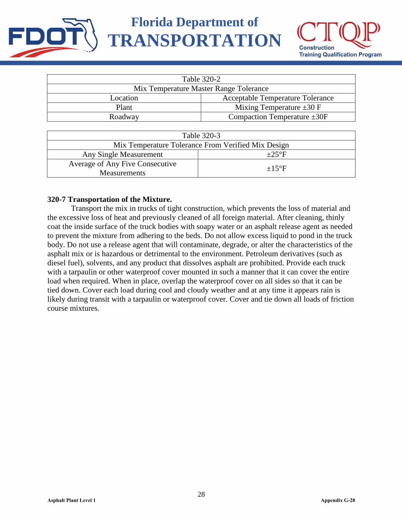
320-6 Preparation of the Mixture. 320-6.1 Mixing: After the aggregate is dried and properly proportioned, mix the aggregate, along with any other components, with the asphalt binder to produce a thoroughly and uniformly coated mixture. 320-6.2 Storage: If necessary, store the asphalt mixture in a surge bin or hot storage silo for a maximum of 72 hours. For FC-5 mixtures, store the asphalt mixture in a surge bin or hot storage silo for a maximum of one hour. 320-6.3 Mix Temperature: Produce the mixture with a temperature within the master range as defined in Table 320-2. 320-6.3.1 Test Requirements: Determine the temperature of the completed mixture using a quick-reading thermometer through a hole in the side of the loaded truck immediately after loading. Locate a 1/4 inch hole on both sides of the truck body within the middle third of the length of the body, and at a distance from 6 to 10 inches above the surface supporting the mixture. If a truck body already has a hole located in the general vicinity of the specified location, use this hole. At the Engineer’s discretion, the Contractor may take the temperature of the load over the top of the truck in lieu of using the hole in the side of the truck. 320-6.3.2 Test Frequency: The normal frequency for taking asphalt mix temperatures will be for each day, for each design mix on the first five loads and one out of every five loads thereafter. Take the temperature of the asphalt mix at the plant and at the roadway before the mix is placed at the normal frequency. Record the temperature on the front of the respective delivery ticket. The Engineer shall review the plant and roadway temperature readings and may take additional temperature measurements at any time. If any single load at the plant or at the roadway is within the master range shown in Table 320-2 but does not meet the criteria shown in Table 320-3 (for single measurements or the average of five consecutive measurements), the temperature of every load will be monitored until the temperature falls within the specified tolerance range in Table 320-3; at this time the normal frequency may be resumed. For warm mix asphalt, the Contractor may produce the first five loads of the production day and at other times when approved by the Engineer, at a hot mix asphalt temperature not to exceed 330°F for purposes of heating the asphalt paver. For this situation, the upper tolerances of Tables 320-2 and 320-3 as applied to the warm mix asphalt mix design do not apply. 320-6.3.3 Rejection Criteria: Reject any load or portion of a load of asphalt mix at the plant or at the roadway with a temperature outside of its respective master range shown in Table 320-2. Notify the Engineer of the rejection immediately.
Asphalt Plant Level 1 Appendix G-27
Florida Department of TRANSPORTATION
28
Table 320-2 Mix Temperature Master Range Tolerance
Location Acceptable Temperature Tolerance Plant Mixing Temperature ±30 F
Roadway Compaction Temperature ±30F
Table 320-3 Mix Temperature Tolerance From Verified Mix Design
Any Single Measurement ±25°F Average of Any Five Consecutive
Measurements ±15°F
320-7 Transportation of the Mixture. Transport the mix in trucks of tight construction, which prevents the loss of material and the excessive loss of heat and previously cleaned of all foreign material. After cleaning, thinly coat the inside surface of the truck bodies with soapy water or an asphalt release agent as needed to prevent the mixture from adhering to the beds. Do not allow excess liquid to pond in the truck body. Do not use a release agent that will contaminate, degrade, or alter the characteristics of the asphalt mix or is hazardous or detrimental to the environment. Petroleum derivatives (such as diesel fuel), solvents, and any product that dissolves asphalt are prohibited. Provide each truck with a tarpaulin or other waterproof cover mounted in such a manner that it can cover the entire load when required. When in place, overlap the waterproof cover on all sides so that it can be tied down. Cover each load during cool and cloudy weather and at any time it appears rain is likely during transit with a tarpaulin or waterproof cover. Cover and tie down all loads of friction course mixtures.
Asphalt Plant Level 1 Appendix G-28
Florida Department of TRANSPORTATION
29
SECTION 327 MILLING OF EXISTING ASPHALT PAVEMENT
327-1 Description. Remove existing asphalt concrete pavement by milling to improve the rideability and cross slope of the finished pavement, to lower the finished grade adjacent to existing curb prior to resurfacing, or to completely remove existing pavement. When milling to improve rideability, the Plans will specify an average depth of cut. Take ownership of milled material.
327-2 Equipment. Provide a milling machine capable of maintaining a depth of cut and cross slope that will achieve the results specified in the Contract Documents. Use a machine with a minimum overall length (out to out measurement excluding the conveyor) of 18 feet and a minimum cutting width of 6 feet. Equip the milling machine with a built-in automatic grade control system that can control the transverse slope and the longitudinal profile to produce the specified results. To start the project, the Engineer will approve any commercially manufactured milling machine that meets the above requirements. If it becomes evident after starting milling that the milling machine cannot consistently produce the specified results, the Engineer will reject the milling machine for further use. The Contractor may use a smaller milling machine when milling to lower the grade adjacent to existing curb or other areas where it is impractical to use the above described equipment. Equip the milling machine with means to effectively limit the amount of dust escaping during the removal operation. For complete pavement removal, the Engineer may approve the use of alternate removal and crushing equipment in lieu of the equipment specified above.
327-3 Construction. 327-3.1 General: Remove the existing raised reflective pavement markers prior to milling. Include the cost of removing existing pavement markers in the price for milling. When milling to improve rideability or cross slope, remove the existing pavement to the average depth specified in the Plans, in a manner that will restore the pavement surface to a uniform cross-section and longitudinal profile. The Engineer may require the use of a stringline to ensure maintaining the proper alignment. Establish the longitudinal profile of the milled surface in accordance with the milling plans. Ensure that the final cross slope of the milled surface parallels the surface cross slope shown in the Plans or as directed by the Engineer. Establish the cross slope of the milled surface by a second sensing device near the outside edge of the cut or by an automatic cross slope control mechanism. The Plans may waive the requirement of automatic grade or cross slope controls where the situation warrants such action. Operate the milling machine to minimize the amount of dust being emitted. The Engineer may require prewetting of the pavement.
Asphalt Plant Level 1 Appendix G-29
Florida Department of TRANSPORTATION
30
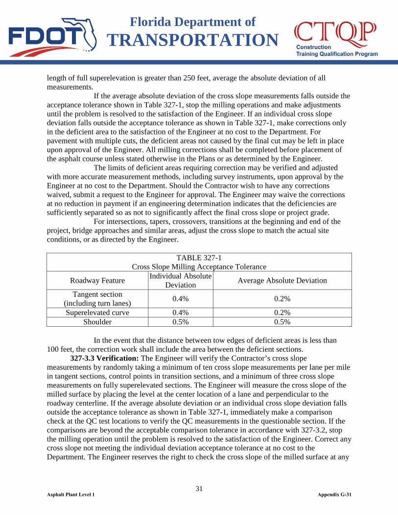
Provide positive drainage of the milled surface and the adjacent pavement. Perform this operation on the same day as milling. Repave all milled surfaces no later than the day after the surface was milled. If traffic is to be maintained on the milled surface prior to the placement of the new asphalt concrete, provide suitable transitions between areas of varying thickness to create a smooth longitudinal riding surface. Produce a pattern of striations that will provide an acceptable riding surface. The Engineer will control the traveling speed of the milling machine to produce a texture that will provide an acceptable riding surface. Prior to opening an area which has been milled to traffic, sweep the pavement with a power broom or other approved equipment to remove, to the greatest extent practicable, fine material which will create dust under traffic. Sweep in a manner that will minimize the potential for creation of a traffic hazard and to minimize air pollution. Sweep the milled surface with a power broom prior to placing asphalt concrete. In urban and other sensitive areas, use a street sweeper or other equipment capable of removing excess milled materials and controlling dust. Obtain the Engineer’s approval of such equipment, contingent upon its demonstrated ability to do the work. Perform the sweeping operation immediately after the milling operations or as directed by the Engineer. 327-3.2 Quality Control Requirements: Furnish an electronic level with a length of 4 feet and an accuracy of plus or minus 0.1 degree approved by the Engineer for the control of cross slope. Make this electronic level available at the jobsite at all times during milling operations. Calibrate and compare electronic levels in accordance with 330-9.3.1 at a minimum frequency of once per day before any milling operation. Multiple cuts may be made to achieve the required pavement configuration or depth of cut. Measure the cross slope of the milled surface by placing the level at the center location of a lane and perpendicular to the roadway centerline. Record all the measurements to the nearest 0.1% on an approved form and submit to the Engineer for documentation. 1. Tangent Sections: Measure the cross slope per lane at a minimum frequency of one measurement every 100 feet. Calculate the absolute deviation of cross slope at each measurement and then average the absolute deviation of ten consecutive cross slope measurements. The absolute deviation is the positive value of a deviation. When the average absolute deviation cross slope is consistently within the acceptance tolerance as shown in Table 327-1 and upon approval by the Engineer, the frequency of the cross slope measurements can be reduced to one measurement every 200 feet during milling operations. 2. Superelevated Sections: Measure the cross slope every 100 feet per lane within the length of full superelevation. Calculate the absolute deviation of each measurement and then average the absolute deviation of ten consecutive cross slope measurements. For every transition section, measure the cross slope at control points identified in the Plans or, if not shown in the Plans, at a control point at a location of 0.0% cross slope. For curves where the length of the fully superelevated section is less than 250 feet, measure the cross slope at the beginning point, midpoint and ending point of the fully superelevated section, calculate the absolute deviation and average. When the number of measurements is less than ten and the
Asphalt Plant Level 1 Appendix G-30
Florida Department of TRANSPORTATION
31
length of full superelevation is greater than 250 feet, average the absolute deviation of all measurements. If the average absolute deviation of the cross slope measurements falls outside the acceptance tolerance shown in Table 327-1, stop the milling operations and make adjustments until the problem is resolved to the satisfaction of the Engineer. If an individual cross slope deviation falls outside the acceptance tolerance as shown in Table 327-1, make corrections only in the deficient area to the satisfaction of the Engineer at no cost to the Department. For pavement with multiple cuts, the deficient areas not caused by the final cut may be left in place upon approval of the Engineer. All milling corrections shall be completed before placement of the asphalt course unless stated otherwise in the Plans or as determined by the Engineer. The limits of deficient areas requiring correction may be verified and adjusted with more accurate measurement methods, including survey instruments, upon approval by the Engineer at no cost to the Department. Should the Contractor wish to have any corrections waived, submit a request to the Engineer for approval. The Engineer may waive the corrections at no reduction in payment if an engineering determination indicates that the deficiencies are sufficiently separated so as not to significantly affect the final cross slope or project grade. For intersections, tapers, crossovers, transitions at the beginning and end of the project, bridge approaches and similar areas, adjust the cross slope to match the actual site conditions, or as directed by the Engineer.
TABLE 327-1 Cross Slope Milling Acceptance Tolerance
Roadway Feature Individual Absolute Deviation Average Absolute Deviation
Tangent section (including turn lanes) 0.4% 0.2%
Superelevated curve 0.4% 0.2% Shoulder 0.5% 0.5%
In the event that the distance between tow edges of deficient areas is less than 100 feet, the correction work shall include the area between the deficient sections. 327-3.3 Verification: The Engineer will verify the Contractor’s cross slope measurements by randomly taking a minimum of ten cross slope measurements per lane per mile in tangent sections, control points in transition sections, and a minimum of three cross slope measurements on fully superelevated sections. The Engineer will measure the cross slope of the milled surface by placing the level at the center location of a lane and perpendicular to the roadway centerline. If the average absolute deviation or an individual cross slope deviation falls outside the acceptance tolerance as shown in Table 327-1, immediately make a comparison check at the QC test locations to verify the QC measurements in the questionable section. If the comparisons are beyond the acceptable comparison tolerance in accordance with 327-3.2, stop the milling operation until the problem is resolved to the satisfaction of the Engineer. Correct any cross slope not meeting the individual deviation acceptance tolerance at no cost to the Department. The Engineer reserves the right to check the cross slope of the milled surface at any
Asphalt Plant Level 1 Appendix G-31
Florida Department of TRANSPORTATION
32
time by taking cross slope measurements at any location.
327-4 Milled Surface. Provide a milled surface with a reasonably uniform texture, within 1/4 inch of a true profile grade, and with no deviation in excess of 1/4 inch from a straightedge applied to the pavement perpendicular to the centerline. Ensure that the variation of the longitudinal joint between multiple cut areas does not exceed 1/4 inch. The Engineer may accept areas varying from a true surface in excess of the above stated tolerance without correction if the Engineer determines that they were caused by a pre-existing condition which could not have reasonably been corrected by the milling operations. Correct any unsuitable texture or profile, as determined by the Engineer, at no additional expense to the Department. The Engineer may require remilling of any area where a surface lamination causes a non-uniform texture to occur.
327-5 Method of Measurement. The quantity to be paid for will be the plan quantity area, in square yards, over which milling is completed and accepted.
327-6 Basis of Payment. Price and payment will be full compensation for all work specified in this Section, including hauling off and stockpiling or otherwise disposing of the milled material. Payment will be made under:
Item No. 327- 70- Milling Existing Asphalt Pavement - per square yard.
Asphalt Plant Level 1 Appendix G-32

Florida Department of TRANSPORTATION
33
SECTION 330 HOT MIX ASPHALT -
GENERAL CONSTRUCTION REQUIREMENTS
330-1 Description. This Section specifies the basic equipment and construction requirements for hot mix asphalt (including warm mix asphalt) pavements and bases. Establish and maintain a quality control system that provides assurance that all materials, products and completed construction submitted for acceptance meet Contract requirements.
330-2 Quality Control (QC) Requirements. 330-2.1 Minimum QC Requirements: In addition to the requirements set forth in Section 105, describe in the Quality Control Plan (QCP) how the following attributes will be monitored: pavement density, mix temperature, pavement smoothness, pavement cross-slope, mix spread rate, and pavement texture, including methods for monitoring pavement segregation and the corrective actions that will be taken to resolve any identified problems. Perform as a minimum, the following activities necessary to maintain process control and meet Specification requirements: 1. Pavement Density: Monitor the pavement temperature with an infrared temperature device so that compaction is completed before the surface temperature of the pavement drops to the extent that effective compaction may not be achieved or the rollers begin to damage the pavement. Monitor the roadway density with either 6 inch diameter roadway cores, a nuclear density gauge, or other density measuring device, at a minimum frequency of once per 1,500 feet of pavement. 2. Mix Temperature: Determine the mix temperature at the roadway for the first five loads and one out of every five loads thereafter. 3. Mix Spread Rate: Monitor the mix spread rate at the beginning of each day’s production, and as needed to control the operations, at a minimum of once per 200 tons placed. When determining the spread rate, use, at a minimum, an average of five truckloads of mix. 4. Pavement Texture: Monitor the pavement texture to minimize pavement segregation. Use density gauges, infrared temperature measurement devices, or roadway cores at the beginning of each day’s production, and as necessary, both at truck exchanges and during normal paving operations. 5. Reporting: Ensure the accuracy of the Quality Control Roadway Reports on the Department’s approved form to reflect the actual surface area of the finished work and be in compliance with the requirements of the Contract Documents. 330-2.2 Personnel Qualifications: Provide QC Technicians in accordance with Section 105.
330-3 Limitations of Operations. 330-3.1 Weather Limitations: Do not transport asphalt mix from the plant to the roadway unless all weather conditions are suitable for the paving operations.
Asphalt Plant Level 1 Appendix G-33

Florida Department of TRANSPORTATION
34
330-3.2 Limitations of Paving Operations: 330-3.2.1 General: Place the mixture only when the surface upon which it is to be placed has been previously prepared, is intact, firm, dry, clean, and the tack or prime coat, with acceptable spread rate, is properly broken or cured. Do not place friction course until the adjacent shoulder area has been dressed and grassed. 330-3.2.2 Ambient Air Temperature: Place the mixture only when the air temperature in the shade and away from artificial heat meets requirements of Table 330-1. The minimum ambient temperature requirement may be reduced by 5ºF when using warm mix technology, if mutually agreed to by both the Engineer and the Contractor.
Table 330-1 Ambient Air Temperature Requirements for Paving
Layer Thickness or Asphalt Binder Type Minimum Temperature (°F) ≤ 1 inch 50
Any mixture > 1 inch containing a PG asphalt binder having a high temperature designation ≥ 76°C 45
Any mixture > 1 inch containing a PG asphalt binder having a high temperature designation < 76°C 40
FC-5(1) 65 (1)As an exception, place the mixture at temperatures no lower than 60ºF, only when approved by the Engineer based on the Contractor’s demonstrated ability to achieve a satisfactory surface texture and appearance of the finished surface. The minimum ambient temperature may be further reduced to 55ºF when using warm mix technology, if agreed to by both the Engineer and the Contractor. 330-3.2.3 Rain and Surface Conditions: Immediately cease transportation of asphalt mixtures from the plant when rain begins at the roadway. Do not place asphalt mixtures while rain is falling, or when there is water on the surface to be covered. Once the rain has stopped and standing water has been removed from the tacked surface to the satisfaction of the Engineer and the temperature of the mixture caught in transit still meets the requirements as specified in 320-6.3, the Contractor may then place the mixture caught in transit. 330-3.2.4 Wind: Do not place the mixture when the wind is blowing to such an extent that proper and adequate compaction cannot be maintained or when sand, dust, etc., are being deposited on the surface being paved to the extent that the bond between layers will be diminished.
330-4 Surface Preparation. 330-4.1 Cleaning: Prior to placing the mixture, clean the surface of the base or underlying pavement of all loose and deleterious material by the use of power brooms or blowers, supplemented by hand brooming where necessary. 330-4.1.1 Application over Asphalt Rubber Membrane Interlayer (ARMI): Where an asphalt mix is to be placed over a newly constructed ARMI, do not sweep or otherwise disturb the cover material prior to placing the asphalt mix, unless directed by the Engineer.
Asphalt Plant Level 1 Appendix G-34
Florida Department of TRANSPORTATION
35
330-4.2 Tacking: Apply a tack coat on all existing pavement surfaces that are to be overlaid with an asphalt mix as specified in Section 300 and between successive layers of all asphalt mixes. Apply a tack coat on freshly primed bases only when so directed by the Engineer.
330-5 Paving Equipment. 330-5.1 General Requirements: Use equipment that is mechanically sound and capable of consistently meeting the requirements of these Specifications. 330-5.2 Asphalt Paver: 330-5.2.1 General: Provide an asphalt paver that is self-propelled, can be steered, and is equipped with a receiving and distribution hopper and a mechanical screed. Use a mechanical screed capable of adjustment to regulate the depth of material spread and to produce the desired cross-section. 330-5.2.2 Automatic Screed Control: For all asphalt courses placed with an asphalt paver, equip the paver with automatic longitudinal screed controls of either the skid type, traveling stringline type, or non-contact averaging ski type with a minimum length of 25 feet. On the final layer of asphalt base, overbuild, and structural courses, and for friction courses, use the joint matcher in lieu of the skid, traveling stringline, or non-contact averaging ski on all passes after the initial pass. Equip the asphalt paver with electronic cross slope controls. 330-5.2.3 Screed Width: Provide an asphalt paver having a screed width greater than 8 feet when required to pave full width lanes. Do not use extendable screed strike-off devices that do not provide preliminary compaction of the mat in place of fixed screed extensions. Use a strike-off device only on irregular areas that would normally be done by hand and on shoulders 5 feet or less in width. When using the strike-off device on shoulders in lieu of an adjustable screed extension, demonstrate the ability to obtain an acceptable texture, density, and thickness. When using an extendable screed device to extend the screed’s width on the full width lane or shoulder by 24 inches or greater, the Engineer will require an auger extension, paddle, or kicker device unless written documentation from the manufacturer is provided that these are not necessary. 330-5.3 Rollers: 330-5.3.1 Steel-Wheeled Rollers: Provide compaction equipment capable of meeting the density requirements described in these Specifications. In the event that density testing is not required, and the standard rolling pattern is used, provide a tandem steel-wheeled roller weighing 5 to 15 tons for breakdown rolling. For finish rolling, use a separate roller with a weight of 5 to 15 tons. Variations from these requirements shall be approved by the Engineer. 330-5.3.2 Traffic Rollers: Provide compaction equipment capable of meeting the density requirements described in the Specifications. In the event that density testing is not required, and the standard rolling pattern is used, provide a self-propelled, pneumatic-tired traffic roller equipped with at least seven smooth-tread, low pressure tires, equipped with pads or scrapers on each tire. Maintain the tire pressure between 50 and 55 psi or as specified by the manufacturer. Use rollers with a minimum weight of 6 tons. Do not use wobble-wheeled rollers. Variations from these requirements shall be approved by the Engineer.
Asphalt Plant Level 1 Appendix G-35
Florida Department of TRANSPORTATION
36
330-5.3.3 Prevention of Adhesion: Do not allow the mixture to adhere to the wheels of any rollers. Do not use fuel oil or other petroleum distillates to prevent adhesion. Do not use any method which results in water being sprinkled directly onto the mixture. 330-5.4 Coring Equipment: Furnish a suitable saw or drill for obtaining the required density cores. 330-5.5 Hand Tools: Provide the necessary hand tools such as rakes, shovels, and other similar tools, and a suitable means for keeping them clean. Do not use diesel fuel or other petroleum based solvents contained in an open container for cleaning purposes on the paver.
330-6 Placing Mixture. 330-6.1 Requirements Applicable to All Pavement Types: 330-6.1.1 Alignment of Edges: Place all asphalt mixtures by the stringline method to obtain an accurate, uniform alignment of the pavement edge. As an exception, pavement edges adjacent to curb and gutter or other true edges do not require a stringline. Control the unsupported pavement edge to ensure that it will not deviate more than plus or minus1.5 inches from the stringline. 330-6.1.2 Paving Width: If necessary due to the traffic requirements, place the mixture in strips in such a manner as to provide for the passage of traffic. As an option, where the road is closed to traffic, place the mixture to the full width with machines traveling in echelon. 330-6.1.3 Mix Temperature: Maintain the temperature of the mix at the time of paving within the master range as defined in 320-6.3. The minimum frequency for taking mix temperatures on the roadway will be as indicated in 320-6.3. Any load or portion of a load of asphalt mix on the roadway with a temperature outside of the master range shall be rejected for use on the project. Immediately notify the Engineer of the rejection. 330-6.1.4 Speed of Paver: Establish the forward speed of the asphalt paver based on the rate of delivery of the mix to the roadway but not faster than the optimum speed needed to adequately compact the pavement. 330-6.1.5 Thickness and Spread Rate of Layers: Construct each layer as defined in the following table:
Table 330-2 Thickness and Target Spread Rate Requirements
Mix Type Specification Section and Article Type SP 334-1 Type FC 337-8 Type B 234-8 ATPB 287-8
330-6.1.5.1 Thickness Control: Ensure the spread rate is within 5% of the target spread rate. When determining the spread rate, use, at a minimum, an average of five truckloads of mix. When the average spread rate is beyond plus or minus 5% of the target spread rate, monitor the thickness of the pavement layer closely and adjust the construction operations.
Asphalt Plant Level 1 Appendix G-36
Florida Department of TRANSPORTATION
37
If the Contractor fails to maintain an average spread rate within plus or minus 5% of the target spread rate for two consecutive days, the Engineer may elect to stop the construction operation at any time until the issue is resolved. 330-6.1.5.2 Maximum Spread Rate Tolerances: When the average spread rate for the total structural or friction course pavement thickness measured in accordance with 330-6.1.5.1 exceeds the maximum spread rate tolerances shown in Table 330-3, address the unacceptable pavement in accordance with 330-9.5.
Table 330-3 Maximum Spread Rate Tolerances
Course Design Thickness Spread Rate Tolerance Structural ≥ 2.5 inches ± 50 lbs per sy Structural < 2.5 inches ± 25 lbs per sy
Friction (dense) - ± 25 lbs per sy Friction (open) - ± 15 lbs per sy
As an exception, the Engineer may allow the Contractor to leave areas in place if it is determined by the Engineer that the deficiency is not a significant detriment to the pavement quality. A reduction to the pay item quantity will be made in accordance with 330-9.5.2. 330-6.1.6 Correcting Defects: Before starting any rolling, check the surface; correct any irregularities; remove all drippings, sand accumulations from the screed, and fat spots from any source; and replace them with satisfactory material. Do not skin patch. When correcting a depression while the mixture is hot, scarify the surface and add fresh mixture. 330-6.1.7 Hand Work: In limited areas where the use of the paver is impossible or impracticable, the Contractor may place and finish the mixture by hand.
330-7 Compacting Mixture. 330-7.1 General Requirements: When density testing for acceptance is required, select equipment, sequence, and coverage (number of times the roller passes over a given area of pavement) of rolling to meet the specified density requirement. Regardless of the rolling procedure used, complete the final rolling before the surface temperature of the pavement drops to the extent that effective compaction may not be achieved or the rollers begin to damage the pavement. 330-7.2 Standard Rolling Procedure: When density testing for acceptance is not required, propose an alternative rolling pattern to be approved by the Engineer or use the following standard rolling procedure: 1. Breakdown rolling: Provide two static coverages with a tandem steel-wheeled roller, following as close behind the paver as possible without pick-up, undue displacement, or blistering of the material. 2. Intermediate rolling: Provide five static coverages with a pneumatic-tired roller, following as close behind the breakdown rolling operation as the mix will permit.
Asphalt Plant Level 1 Appendix G-37
Florida Department of TRANSPORTATION
38
3. Finish rolling: Provide one static coverage with a tandem steel-wheeled roller, after completing the breakdown rolling and intermediate rolling, but before the surface pavement temperature drops to the extent that effective compaction may not be achieved or the rollers begin to damage the pavement. 330-7.3 Rolling Procedures: Utilize procedures that will uniformly compact the pavement layer to the desired density level, while meeting the appropriate smoothness requirements, without damaging the pavement surface, crushing aggregate or leaving excessive roller marks, roller heads, or ripples. While rolling is in progress, monitor the surface continuously, and adjust the compaction operations to comply with the surface requirements. 330-7.4 Compaction of Areas Inaccessible to Rollers: Use hand tamps or other satisfactory means to compact areas which are inaccessible to a roller, such as areas adjacent to curbs, gutters, bridges, manholes, etc. 330-7.5 Correcting Defects: Do not allow the compaction equipment to deposit contaminants onto the pavement surface. Remove and replace any areas damaged by such deposits as directed by the Engineer. Correct any depressions that develop before completing the rolling by loosening the mixture and adding new mixture to bring the depressions to a true surface. Should any depression remain after obtaining the final compaction, remove the full depth of the mixture, and replace it with sufficient new mixture to form a true and even surface. Correct all defects prior to laying the subsequent course. 330-7.6 Use of Traffic Roller: Use a traffic roller on the first overbuild course. Use a traffic roller or vibratory roller (unless restricted by the Contract Documents) on the first structural layer placed on an ARMI. 330-7.7 Compaction at Bridge Structures: Compact asphalt mixtures placed over bridge decks and approach slabs using static compaction only. Utilize the standard rolling procedure described in 330-7.2 or an alternative procedure approved by the Engineer.
330-8 Joints. 330-8.1 General: When laying fresh mixture against the exposed edges of joints, place it in close contact with the exposed edge to produce an even, well-compacted joint after rolling. 330-8.2 Transverse Joints: Place the mixture as continuously as possible to minimize transverse joints. When constructing permanent transverse joints, meet the surface requirements as defined in 330-9. Construct temporary transverse joints in such a manner to allow traffic to pass over it. When resuming the paving operation, construct a transverse joint by cutting back on the previously placed pavement at a location where the straightedge requirements are met. At the project limits, tie into the adjoining pavement layers as shown in the Plans. 330-8.3 Longitudinal Joints: Place each layer of pavement so that all longitudinal construction joints are offset 6 to 12 inches laterally between successive layers. Plan offsets in advance so that longitudinal joints of the friction course are not in wheel path areas. The longitudinal joints for friction course layers should be within 6 inches of the lane edge or at the center of the lane. The Engineer may waive this requirement where offsetting is not feasible due to the sequence of construction. 330-8.4 Placing Asphalt Next to Concrete Pavement: When placing asphalt next to concrete pavement, construct the joint as shown in the Plans.
Asphalt Plant Level 1 Appendix G-38

Florida Department of TRANSPORTATION
39
330-9 Surface Requirements. 330-9.1 General: Construct a smooth pavement with good surface texture and the proper cross-slope. 330-9.2 Texture of the Finished Surface of Paving Layers: Produce a finished surface of uniform texture and compaction with no pulled, torn, raveled, crushed or loosened portions and free of segregation, bleeding, flushing, sand streaks, sand spots, or ripples. Address any pavement not meeting the requirements of this specification in accordance with 330-9.5. For dense graded structural and friction course mixtures, in areas not defined to be a density testing exception per 334-5.1.2, obtain for the Engineer three 6 inch diameter roadway cores at locations visually identified by the Engineer to be segregated. The Engineer will determine the density of each core in accordance with FM 1-T 166 and calculate the percent Gmm of the segregated area using the average Gmb of the roadway cores and the QC sublot Gmm for the questionable material. If the average percent Gmm is less than 90.0, address the segregated area in accordance with 330-9.5. Do not use asphalt concrete mixtures containing aggregates that cause a different color appearance in the final wearing surface unless the section is greater than or equal to one mile in length and across the full width of the pavement, including shoulders and turn lanes. Exceptions to these requirements will be permitted if approved by the Engineer. 330-9.3 Cross Slope: Construct a pavement surface with cross slopes in compliance with the requirements of the Contract Documents. Furnish an electronic level with a length of 4 feet and an accuracy of 0.1 degree, approved by the Engineer for the control of cross slope. Make this electronic level available at the jobsite at all times during paving operations. 330-9.3.1 QC Requirements: Calibrate the electronic levels a minimum of once per day before paving operations begin, in accordance with manufacturer’s instructions. Compare the QC level with the Verification level before paving operations begin, and at any time as directed by the Engineer. If the comparison between the QC and Verification levels is within the comparison tolerance of plus or minus 0.2%, the QC level is considered to compare favorably and can be used for measurement and acceptance of cross slopes. If the levels do not compare favorably, perform a second comparison using another calibrated electronic level (FDOT or Contractor) for resolution. If this resolution level compares favorably with the QC level, the QC level is considered to be verified. If the second level does not compare favorably with the QC level, discontinue the use of the QC electronic level and obtain another approved electronic level that meets the requirements of this specification. Regardless of the comparison analysis outcome, the Contractor assumes all risk associated with placing the pavement at the correct cross slope. Measure the cross slope of the compacted pavement surface by placing the level at the center location of a lane and perpendicular to the roadway centerline. Record all measurements to the nearest 0.1% on the Cross Slope Measurement Data Form and submit to the Engineer for documentation. 1. Tangent Sections: Measure the cross slope at a minimum frequency of one measurement every 100 feet per lane. Calculate the absolute deviation of each cross slope measurement and then average the absolute deviations of ten consecutive cross slope measurements. (The absolute deviation is the positive value of a deviation) When the average
Asphalt Plant Level 1 Appendix G-39
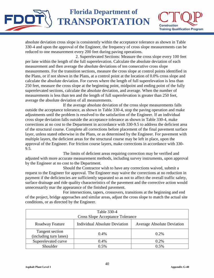
Florida Department of TRANSPORTATION
40
absolute deviation cross slope is consistently within the acceptance tolerance as shown in Table 330-4 and upon the approval of the Engineer, the frequency of cross slope measurements can be reduced to one measurement every 200 feet during paving operations. 2. Superelevated Sections: Measure the cross slope every 100 feet per lane within the length of the full superelevation. Calculate the absolute deviation of each measurement and then average the absolute deviations of ten consecutive cross slope measurements. For the transition sections, measure the cross slope at control points identified in the Plans, or if not shown in the Plans, at a control point at the location of 0.0% cross slope and calculate the absolute deviation. For curves where the length of full superelevation is less than 250 feet, measure the cross slope at the beginning point, midpoint and ending point of the fully superelevated sections, calculate the absolute deviation, and average. When the number of measurements is less than ten and the length of full superelevation is greater than 250 feet, average the absolute deviation of all measurements. If the average absolute deviation of the cross slope measurements falls outside the acceptance tolerance, as shown in Table 330-4, stop the paving operation and make adjustments until the problem is resolved to the satisfaction of the Engineer. If an individual cross slope deviation falls outside the acceptance tolerance as shown in Table 330-4, make corrections at no cost to the Department in accordance with 330-9.5 to address the deficient area of the structural course. Complete all corrections before placement of the final pavement surface layer, unless stated otherwise in the Plans, or as determined by the Engineer. For pavement with multiple layers, the deficient areas for the structural course may be left in place, upon the approval of the Engineer. For friction course layers, make corrections in accordance with 330-9.5. The limits of deficient areas requiring correction may be verified and adjusted with more accurate measurement methods, including survey instruments, upon approval by the Engineer at no cost to the Department. Should the Contractor wish to have any corrections waived, submit a request to the Engineer for approval. The Engineer may waive the corrections at no reduction in payment if the deficiencies are sufficiently separated so as not to affect the overall traffic safety, surface drainage and ride quality characteristics of the pavement and the corrective action would unnecessarily mar the appearance of the finished pavement. For intersections, tapers, crossovers, transitions at the beginning and end of the project, bridge approaches and similar areas, adjust the cross slope to match the actual site conditions, or as directed by the Engineer.
Table 330-4 Cross Slope Acceptance Tolerance
Roadway Feature Individual Absolute Deviation Average Absolute Deviation
Tangent section (including turn lanes) 0.4% 0.2%
Superelevated curve 0.4% 0.2% Shoulder 0.5% 0.5%
Asphalt Plant Level 1 Appendix G-40
Florida Department of TRANSPORTATION
41
In the event that the distance between two edges of deficient areas is less than 100 feet, the correction work shall include the area between the deficient sections. 330-9.3.2 Verification: The Engineer will verify the Contractor’s cross slope measurements by randomly taking a minimum of ten cross slope measurements per lane per mile in tangent sections, control points in transition sections, and a minimum of three cross slope measurements on fully superelevated sections over a day’s production. The Engineer will measure the cross slope of the compacted pavement surface by placing the level at the center location of a lane and perpendicular to the roadway centerline. If the average absolute deviation or an individual cross slope deviation falls outside of the acceptance tolerance as shown in Table 330-4, immediately make a comparison check at the QC test locations to verify the QC measurements in the section. If the comparisons are beyond the acceptable comparison tolerance in accordance with 330-9.3.1, stop the paving operations until the issue is resolved to the satisfaction of the Engineer. Correct any cross slope not meeting the individual deviation acceptance tolerance in accordance with 330-9.5 at no cost to the Department. The Engineer reserves the right to check the pavement cross slope at any time by taking cross slope measurements at any location. 330-9.4 Pavement Smoothness: Construct a smooth pavement meeting the requirements of this Specification. 330-9.4.1 General: Furnish a 15 foot manual and a 15 foot rolling straightedge meeting the requirements of FM 5-509. Obtain a smooth surface on all pavement courses placed, and then straightedge all layers as required by this Specification. 330-9.4.2 Test Method: Perform all straightedge testing in accordance with FM 5-509 in the outside wheel path of each lane. The Engineer may require additional testing at other locations within the lane. 330-9.4.3 Traffic Control: Provide traffic control in accordance with Section 102 and the Design Standards Index Nos. 607 or 619 during all testing. When traffic control cannot be provided in accordance with Index Nos. 607 or 619, submit an alternative Traffic Control Plan as specified in 102-4. Include the cost of this traffic control in the Contract bid prices for the asphalt items. 330-9.4.4 Process Control Testing: Assume full responsibility for controlling all paving operations and processes such that the requirements of these Specifications are met at all times. 330-9.4.5 QC Testing: 330-9.4.5.1 General: Straightedge the final Type SP structural layer and friction course layer in accordance with 330-9.4.2, with the exception that if the method of acceptance is by laser profiler, then straightedging of the friction course layer is not required. Test all pavement lanes and ramps where the width is constant and document all deficiencies in excess of 3/16 inch on a form approved by the Engineer. 330-9.4.5.2 Straightedge Exceptions: Straightedge testing will not be required in the following areas: shoulders, intersections, tapers, crossovers, sidewalks, shared use paths, parking lots and similar areas, or in the following areas when they are less than 250 feet in
Asphalt Plant Level 1 Appendix G-41
Florida Department of TRANSPORTATION
42
length: turn lanes, acceleration/deceleration lanes and side streets. The limits of the intersection will be from stop bar to stop bar for both the mainline and side streets. As an exception, in the event the Engineer identifies a surface irregularity in the above areas that is determined to be objectionable, straightedge and address all deficiencies in excess of 3/8 inch in accordance with 330-9.5. The Engineer may waive straightedge requirements for transverse joints at the beginning and end of the project, at the beginning and end of bridge structures, at manholes, and at utility structures if the deficiencies are caused by factors beyond the control of the Contractor, as determined by the Engineer. In addition, the Engineer may also waive the straightedging requirements on ramps and superelevated sections where the geometrical orientation of the pavement results in an inaccurate measurement with the rolling straightedge. 330-9.4.5.3 Intermediate Layers and Temporary Pavement: When the design speed is 55 mph or greater and the intermediate Type SP layer or temporary pavement is to be opened to traffic, if the Engineer identifies a surface irregularity that is determined to be objectionable, straightedge and address all deficiencies in excess of 3/8 inch within 72 hours of placement in accordance with 330-9.5. 330-9.4.5.4 Final Type SP Structural Layer: Straightedge the final Type SP structural layer in accordance with 330-9.4.2, either behind the final roller of the paving train or as a separate operation. Notify the Engineer of the location and time of straightedge testing a minimum of 48 hours before beginning testing. The Engineer will verify the straightedge testing by observing the QC straight edging operations. Address all deficiencies in excess of 3/16 inch in accordance with 330-9.5. When the final structural course is to be opened to traffic and the design speed is 55 mph or greater, if any defect is 3/8 inch or greater, the Engineer may require deficiencies to be corrected within 72 hours after opening to traffic. 330-9.4.5.5 Friction Course Layer: Where required per 330-9.4.5.1, straightedge the friction course layer in accordance with 330-9.4.2, either behind the final roller of the paving train or as a separate operation upon completion of all paving operations. Notify the Engineer of the location and time of straightedge testing a minimum of 48 hours before beginning testing. The Engineer will verify the straightedge testing by observing the QC straightedging operations. Address all deficiencies in excess of 3/16 inch in accordance with 330-9.5. 330-9.4.6 Acceptance: 330-9.4.6.1 Straightedge Acceptance: For areas of roadways where the design speed is less than 55 miles per hour, acceptance for pavement smoothness of the friction course will be based on verified QC measurements using the straightedge as required by 330-9.4.5. The Engineer will verify the straightedge testing by observing the QC straightedging operations. 330-9.4.6.2 Laser Acceptance: For areas of high speed roadways where the design speed is equal to or greater than 55 miles per hour, acceptance testing for pavement smoothness of the friction course (for mainline traffic lanes only) will be based on the Laser Profiler. Ramps, acceleration and deceleration lanes, and other areas not suitable for testing with
Asphalt Plant Level 1 Appendix G-42
Florida Department of TRANSPORTATION
43
the Laser Profiler will be tested and accepted with the straightedge in accordance with 330-9.4.5.5 and 330-9.4.6.1. The pavement smoothness of each lane will be determined by a Laser Profiler furnished and operated by the Department in accordance with FM 5-549 and a report issued with the Ride Number (RN) reported to one decimal place. If corrections are made, as required following Laser Acceptance, the pavement will not be retested for smoothness using the Laser Profiler. For this testing, the pavement will be divided into 0.1 mile segments. Partial segments equal to or greater than 0.01 mile will be considered as a 0.1 mile segment. The pavement will be accepted as follows: 1) For segments with a RN greater than or equal to 4.0, the pavement will be accepted at full pay. 2) For segments with a RN less than 4.0, the Engineer will further evaluate the data in 0.01 mile intervals for both wheel paths. If the RN is 3.5 or above for all 0.01 mile intervals in both wheel paths, the segment will be accepted at full payment. If the RN is less than 3.5 for one or more 0.01 mile intervals, the segment will be tested with the rolling straightedge in both wheel paths in accordance with FM 5-509. If approved by the Engineer, this straightedging may be completed (in both wheel paths) as part of the QC straightedging operations described in 330-9.4.5.5, prior to testing with the laser profiler. Notify the Engineer of the location and time of straightedge testing a minimum of 48 hours before beginning testing. The Engineer will verify the straightedge testing by observing the QC straightedging operations. Address all deficiencies in excess of 3/16 inch in accordance with 330-9.5. Test and accept areas at the beginning and ending of the project, bridge approaches and departures, and areas where the segment is less than 0.01 mile, with the straightedge in accordance with 330-9.4.5.5 and 330-9.4.6.1. 330-9.5 Unacceptable Pavement: 330-9.5.1 Corrections: Address all areas of unacceptable pavement at no cost to the Department. Retest all corrected areas and assure the requirements of these Specifications are met. 330-9.5.1.1 Structural Layers: Correct all deficiencies, as defined in these Specifications, in the Type SP structural layers by removing and replacing the full depth of the layer, extending a minimum of 50 feet on both sides (where possible) of the defective area for the full width of the paving lane. As an option, for high straightedge deficiencies only, mill the pavement surface the full lane width to a depth and length that is adequate to remove the deficiency. This option only applies if the structural layer is not the final surface layer. 330-9.5.1.2 Friction Course: Correct deficiencies in the friction course or final surface layer by removing and replacing the full depth of the layer, extending a minimum of 50 feet on both sides (where possible) of the defective area for the full width of the paving lane. As an exception, the Engineer may allow the Contractor to leave these areas in place if it is
Asphalt Plant Level 1 Appendix G-43

Florida Department of TRANSPORTATION
44
determined by the Engineer that the deficiency is not a significant detriment to the pavement quality. A reduction to the pay item quantity will be made in accordance with 330-9.5.2. 330-9.5.2 Reduction in Pay Item Quantity: When the Engineer elects to waive corrections, the Department will reduce the pay quantity for the pay item in question by the amount of material that the Contractor would have removed and replaced had the correction been made. When the pay quantity is in tons, the Department will base the reduction on the volume of material that the Contractor would have removed (the length by the lane width by layer thickness) multiplied by the maximum specific gravity of the mix as determined through the following equation: Quantity (tons) = L x W x t x Gmm x 0.0024 Where: L = Lane length (ft.) W = Lane width (ft.) t = Layer thickness (in.) Gmm = Maximum specific gravity from verified mix design For FC-5 open-graded friction course, the Department will base the reduction on the area that the Contractor would have removed (the length by lane width) multiplied by a spread rate of 80 lb/yd2 as determined through the following equation: Quantity (tons) = L x W x 0.0044 Where: L = Lane length (ft.) W = Lane width (ft.)
330-10 Protection of Finished Surface. Keep sections of newly compacted asphalt concrete, which are to be covered by additional courses, clean until the successive course is laid. Do not dump embankment or base material directly on the pavement. Dress shoulders before placing the friction course on adjacent pavement. Equip blade graders operating adjacent to the pavement during shoulder construction with a 2 inch by 8 inch or larger board, or other attachment providing essentially the same results, attached to their blades in such manner that it extends below the blade edge in order to protect the pavement surface from damage by the grader blade. To prevent rutting or other distortion, protect sections of newly finished dense-graded friction course and the last structural layer prior to the friction course from traffic until the surface temperature has cooled below 160ºF. The Contractor may use artificial methods to cool the pavement to expedite paving operations. The Department may direct the Contractor to use artificial cooling methods when maintenance of traffic requires opening the pavement to traffic at the earliest possible time.
Asphalt Plant Level 1 Appendix G-44

Florida Department of TRANSPORTATION
45
SECTION 334 SUPERPAVE ASPHALT CONCRETE
334-1 Description. 334-1.1 General: Construct a Superpave Asphalt Concrete pavement with the type of mixture specified in the Contract Documents, or when offered as alternates, as selected. Superpave mixes are identified as Type SP-9.5, Type SP-12.5 or Type SP-19.0. Meet the requirements of Section 320 for plant and equipment. Meet the general construction requirements of Section 330, except as modified herein, including the provision for Quality Control (QC) Plans and QC Systems as specified in Section 105. 334-1.2 Traffic Levels: The requirements for Type SP Asphalt Concrete mixtures are based on the design traffic level of the project, expressed in 18,000 pound Equivalent Single Axle Loads (ESAL’s). The five traffic levels are as shown in Table 334-1.
Table 334-1 Superpave Traffic Levels
Traffic Level Traffic Level (1x10⁶ ESAL’s) A <0.3 B 0.3 to <3 C 3 to <10 D 10 to <30 E ≥30
The traffic levels for the project are as specified in the Contract Documents. A Type SP mix one traffic level higher than the traffic level specified in the Contract Documents may be substituted, at no cost to the Department (i.e., Traffic Level B may be substituted for Traffic Level A, etc.). 334-1.3 Gradation Classification: The Superpave mixes are classified as fine and are defined in 334-3.2.2. The equivalent AASHTO nominal maximum aggregate size Superpave mixes are as follows:
Type SP-9.5............................................................... 9.5 mm Type SP-12.5........................................................... 12.5 mm Type SP-19.0........................................................... 19.0 mm
334-1.4 Thickness: The total thickness of the Type SP asphalt layers will be the plan thickness as shown in the Contract Documents. Before paving, propose a thickness for each individual layer meeting the requirements of this specification, which when combined with other layers (as applicable) will equal the plan thickness. For construction purposes, the plan thickness and individual layer thickness will be converted to spread rate based on the maximum specific gravity of the asphalt mix being used, as well as the minimum density level, as shown in the following equation: Spread rate (lbs/yd2) = t x Gmm x 43.3
Asphalt Plant Level 1 Appendix G-45
Florida Department of TRANSPORTATION
46
Where: t = Thickness (in.) (plan thickness or individual layer thickness) Gmm = Maximum specific gravity from the verified mix design The weight of the mixture shall be determined as provided in 320-3.2. For target purposes only, spread rate calculations should be rounded to the nearest whole number. Note: Plan quantities are based on a Gmm of 2.540, corresponding to a spread rate of 110 lbs/yd2-in. Pay quantities will be based on the actual maximum specific gravity of the mix being used. 334-1.4.1 Layer Thicknesses - Fine Mixes: The allowable layer thicknesses for fine Type SP Asphalt Concrete mixtures are as follows:
Type SP-9.5................................................. 1 to 1-1/2 inches Type SP-12.5........................................ 1-1/2 to 2-1/2 inches Type SP-19.0............................................... 2 to 3-1/2 inches
In addition to the minimum and maximum thickness requirements, the following restrictions are placed on fine mixes when used as a structural course: Type SP-9.5 - Limited to the top two structural layers, two layers maximum. Type SP-9.5 – May not be used on Traffic Level D and E applications. Type SP-19.0 - May not be used in the final (top) structural layer below FC-5 mixtures. Type SP-19.0 mixtures are permissible in the layer directly below FC-9.5 and FC-12.5 mixtures. 334-1.4.2 Additional Requirements: The following requirements also apply to Type SP Asphalt Concrete mixtures: 1. A minimum 1-1/2 inch initial lift is required over an Asphalt Rubber Membrane Interlayer (ARMI). 2. When construction includes the paving of adjacent shoulders (less than or equal to 5 feet wide), the layer thickness for the upper pavement layer and shoulder must be the same and paved in a single pass, unless called for differently in the Contract Documents. 3. All overbuild layers must be fine Type SP Asphalt Concrete designed at the traffic level as stated in the Contract Documents. Use the minimum and maximum layer thicknesses as specified above unless called for differently in the Contract Documents. On variable thickness overbuild layers, the minimum and maximum allowable thicknesses will be as specified below, unless called for differently in the Contract Documents.
Type SP-9.5.................................................... 3/8 to 2 inches Type SP-12.5.................................................. 1/2 to 3 inches Type SP-19.0........................................ 1-1/2 to 3-1/2 inches
4. Variable thickness overbuild layers constructed using a Type SP-9.5 or SP-12.5 mixtures may be tapered to zero thickness provided the contract documents require a minimum of 1-1/2 inches of dense-graded mix placed over the variable thickness overbuild layer.
334-2 Materials. 334-2.1 General Requirements: Meet the material requirements specified in Division III. Specific references are as follows:
Asphalt Plant Level 1 Appendix G-46
Florida Department of TRANSPORTATION
47
Superpave PG Asphalt Binder ............................Section 916 Coarse Aggregate ................................................Section 901 Fine Aggregate ....................................................Section 902
334-2.2 Superpave Asphalt Binder: Unless specified otherwise in the Contract Documents, use a PG 67-22 asphalt binder. In addition, meet the requirements of 334-2.3. 334-2.3 Reclaimed Asphalt Pavement (RAP) Material: 334-2.3.1 General requirements: RAP may be used as a component of the asphalt mixture subject to the following requirements: 1. When using a PG 76-22 (PMA), or PG 76-22 (ARB), or PG 82-22 (PMA) asphalt binder, limit the amount of RAP material used in the mix to a maximum of 20% by weight of total aggregate. As an exception, amounts greater than 20% RAP by weight of total aggregate can be used if no more than 20% by weight of the total asphalt binder comes from the RAP material. 2. Assume full responsibility for the design, production and construction of asphalt mixes which incorporate RAP as a component material. 3. Use RAP from a Department approved stockpile or millings from a Department project. 4. Provide stockpiled RAP material that is reasonably consistent in characteristics and contains no aggregate particles which are soft or conglomerates of fines. 5. Provide RAP material having a minimum average asphalt binder content of 4.0% by weight of RAP. As an exception, when using fractionated RAP, the minimum average asphalt binder content for the coarse portion of the RAP shall be 2.5% by weight of the coarse portion of the RAP. The coarse portion of the RAP shall be the portion of the RAP retained on the No. 4 sieve. The Engineer may sample the stockpiles to verify that this requirement is met. 334-2.3.2 Material Characterization for Mix Design: Assume responsibility for establishing the asphalt binder content, gradation, and bulk specific gravity (Gsb) of the RAP material based on a representative sampling of the material by roadway cores or stockpile samples. For roadway core samples, assume responsibility for the degradation that will occur during the milling operation. 334-2.3.3 RAP Stockpile Approval: Prior to the incorporation of RAP into the asphalt mixture, stockpile the RAP material and obtain approval for the stockpile by one of the following methods: 1. Continuous stockpile: When RAP is obtained from one or multiple sources and is either processed, blended, or fractionated, and stockpiled in a continuous manner, assure an adequate number of test results are obtained for stockpile approval. Test the RAP material for gradation and asphalt content at a minimum frequency of one sample per 1000 tons with a minimum of six test results. Test the RAP material for Gmm (for Gsb determination) at a minimum frequency of one sample per 5000 tons with a minimum of two test results. Based on visual inspection and a review of the test data, the Engineer will determine the suitability of the stockpiled material. In addition, address in the QC Plan the details and specifics of the processing, sampling, testing and actions to be taken.
Asphalt Plant Level 1 Appendix G-47
Florida Department of TRANSPORTATION
48
2. Non-continuous single stockpile: When an individual stockpile is being constructed, obtain representative samples at random locations and test the RAP material for gradation and asphalt content at a minimum frequency of one sample per 1000 tons with a minimum of six test results. Test the RAP material for Gmm (for Gsb determination) at a minimum frequency of one sample per 5000 tons with a minimum of two test results. Based on visual inspection and a review of the test data, the Engineer will determine the suitability of the stockpiled material. Once the RAP stockpile has been approved, do not add additional material without prior approval of the Engineer. Determine the asphalt binder content and gradation of the RAP material in accordance with FM 5-563 and FM 1-T 030, respectively. Establish the Gsb of the RAP material by using one of the following methods: a. Calculate the Gsb value based upon the effective specific gravity (Gse) of the RAP material, determined on the basis of the asphalt binder content and maximum specific gravity (Gmm) of the RAP material. The Engineer will approve the estimated asphalt binder absorption value used in the calculation. b. Measure the Gsb of the RAP aggregate, in accordance with FM 1-T 084 and FM 1-T 085. Obtain the aggregate by using a solvent extraction method. 334-2.3.4 Pavement Coring Report: When the Contract includes milling of the existing asphalt pavement, the Pavement Coring Report may be available on the Department’s website. 334-2.3.5 Asphalt Binder for Mixes with RAP: Select the appropriate asphalt binder grade based on Table 334-2. Obtain a sample of the mixture for the Engineer within the first 1,000 tons of production and at a continuing frequency of one sample per 4,000 tons of mix. The Engineer reserves the right to change the asphalt binder type and grade at design based on the characteristics of the RAP asphalt binder, and reserves the right to make changes during production.
Table 334-2 Asphalt Binder Grade for Mixes Containing RAP
Percent RAP Asphalt Binder Grade 0 - 15 PG 67-22 16 - 30 PG 58-22
>30 PG 52-28 334-2.4 Recycled Crushed Glass: Recycled crushed glass may be used as a component of the asphalt mixture subject to the following requirements: 1. Consider the recycled crushed glass a local material and meet all requirements specified in 902-6. 2. Limit the amount of recycled crushed glass to a maximum of 15% by weight of total aggregate. 3. Use an asphalt binder that contains a minimum of 0.5% anti-stripping agent by weight of binder. The anti-strip additive shall be one of the products listed on the Approved
Asphalt Plant Level 1 Appendix G-48

Florida Department of TRANSPORTATION
49
Product List (APL). The anti-strip additive shall be introduced into the asphalt binder by the supplier during loading. 4. Do not use recycled crushed glass in friction course mixtures or in structural course mixtures which are to be used as the final wearing surface.
334-3 General Composition of Mixture. 334-3.1 General: Compose the asphalt mixture using a combination of aggregate (coarse, fine or mixtures thereof), mineral filler, if required, and asphalt binder material. Size, grade and combine the aggregate fractions to meet the grading and physical properties of the mix design. Aggregates from various sources may be combined. 334-3.2 Mix Design: 334-3.2.1 General: Design the asphalt mixture in accordance with AASHTO R 35-12, except as noted herein. Prior to the production of any asphalt mixture, submit the proposed mix design with supporting test data indicating compliance with all mix design criteria to the Engineer. For Traffic Level B through E mix designs, include representative samples of all component materials, including asphalt binder. Allow the State Materials Engineer a maximum of four weeks to either conditionally verify or reject the mix as designed. Do not use more than four mix designs per nominal maximum aggregate size per traffic level per binder grade per year, where the year starts at the Notice to Proceed. Exceeding this limitation will result in a maximum Composite Pay Factor (CPF) of 1.00 as defined in 334-8.2 for all designs used beyond this limit. Warm mix technologies (additives, foaming techniques, etc.) listed on the Department’s website may be used in the production of the mix. The URL for obtaining this information, if available, is: http://www.dot.state.fl.us/statematerialsoffice/quality/programs/warmmixasphalt/index.shtm. The Engineer will consider any marked variations from original test data for a mix design or any evidence of inadequate field performance of a mix design as sufficient evidence that the properties of the mix design have changed, and the Engineer will no longer allow the use of the mix design. 334-3.2.2 Mixture Gradation Requirements: Combine the coarse and fine aggregate in proportions that will produce an asphalt mixture meeting all of the requirements defined in this specification and conform to the gradation requirements at design as defined in AASHTO M 323-12, Table 3. Aggregates from various sources may be combined. 334-3.2.2.1 Mixture Gradation Classification: Plot the combined mixture gradation on an FHWA 0.45 Power Gradation Chart. Include the Control Points from AASHTO M 323-12, Table-3, as well as the Primary Control Sieve (PCS) Control Point from AASHTO M 323-12, Table 4. Fine mixes are defined as having a gradation that passes above the primary control sieve control point and above the maximum density line for all sieve sizes smaller than the primary control sieve and larger than the No. 100 sieve. 334-3.2.3 Aggregate Consensus Properties: For Traffic Level C through E mixtures, meet the following consensus properties at design for the aggregate blend. Aggregate consensus properties do not apply to Traffic Level A and B mixtures.
Asphalt Plant Level 1 Appendix G-49

Florida Department of TRANSPORTATION
50
334-3.2.3.1 Coarse Aggregate Angularity: When tested in accordance with ASTM D 5821-01 (2006), meet the percentage of fractured faces requirements specified in AASHTO M 323-12, Table 5. 334-3.2.3.2 Fine Aggregate Angularity: When tested in accordance with AASHTO T 304-11, Method A, meet the uncompacted void content of fine aggregate specified in AASHTO M 323-12, Table 5. 334-3.2.3.3 Flat and Elongated Particles: When tested in accordance with ASTM D 4791-10, (with the exception that the material passing the 3/8 inch sieve and retained on the No. 4 sieve shall be included), meet the requirements specified in AASHTO M 323-12, Table 5. Measure the aggregate using the ratio of 5:1, comparing the length (longest dimension) to the thickness (shortest dimension) of the aggregate particles. 334-3.2.3.4 Sand Equivalent: When tested in accordance with AASHTO T 176-08, meet the sand equivalent requirements specified in AASHTO M 323-12, Table 5. 334-3.2.4 Gyratory Compaction: Compact the design mixture in accordance with AASHTO T 312-12, with the following exception: use the number of gyrations at Ndesign as defined in Table 334-3. Measure the inside diameter of gyratory molds in accordance with AASHTO T 312-12.
Table 334-3 Gyratory Compaction Requirements
Traffic Level Ndesign Number of Gyrations A 50 B 65 C 75 D 100 E 100
334-3.2.5 Design Criteria: Meet the requirements for nominal maximum aggregate size as defined in AASHTO M 323-12, as well as for relative density, VMA, VFA, and dust-to-binder ratio as specified in AASHTO M 323-12, Table 6. Ninitial and Nmaximum requirements are not applicable. 334-3.2.6 Moisture Susceptibility: 1. For Traffic Level A and B mixtures, use a liquid anti-strip additive, at a rate of 0.5% by weight of the asphalt binder. The anti-strip additive must be listed on the APL. Other rates of anti-strip additive may be used upon approval of the Engineer. 2. For Traffic Level C through E mixtures, test 4 inch specimens in accordance with FM 1-T 283. Provide a mixture having a retained tensile strength ratio of at least 0.80 and a minimum tensile strength (unconditioned) of 100 psi. If necessary, add a liquid anti-stripping agent and/or hydrated lime (meeting the requirements of Section 337) in order to meet these criteria. The anti-strip additive must be listed on the APL. 334-3.2.7 Additional Information: In addition to the requirements listed above, provide the following information with each proposed mix design submitted for verification:
Asphalt Plant Level 1 Appendix G-50

Florida Department of TRANSPORTATION
51
1. The design traffic level and the design number of gyrations (Ndesign). 2. The source and description of the materials to be used. 3. The Department source number and the Department product code of the aggregate components furnished from a Department approved source. 4. The gradation and proportions of the raw materials as intended to be combined in the paving mixture. The gradation of the component materials shall be representative of the material at the time of use. Compensate for any change in aggregate gradation caused by handling and processing as necessary. 5. A single percentage of the combined mineral aggregate passing each specified sieve. Degradation of the aggregate due to processing (particularly material passing the No. 200 sieve) should be accounted for and identified. 6. The bulk specific gravity (Gsb) value for each individual aggregate and RAP component, as identified in the Department’s aggregate control program. 7. A single percentage of asphalt binder by weight of total mix intended to be incorporated in the completed mixture, shown to the nearest 0.1%. 8. A target temperature for the mixture at the plant (mixing temperature) and a target temperature for the mixture at the roadway (compaction temperature) in accordance with 320-6.3. Do not exceed a target temperature of 340°F for PG 82-22 (PMA) asphalt binders, 330°F for PG 76-22 (PMA) and PG 76-22 (ARB) asphalt binders, and 315°F for unmodified asphalt binders. 9. Provide the physical properties achieved at four different asphalt binder contents. One of which must be at the optimum asphalt content, and must conform to all specified physical requirements. 10. The name of the Construction Training Qualification Program (CTQP) Qualified Mix Designer. 11. The ignition oven calibration factor. 12. The warm mix technology, if used. 334-3.3 Mix Design Revisions: During production, the Contractor may request a target value revision to a mix design, subject to meeting the following requirements: (1) the target change falls within the limits defined in Table 334-4, (2) appropriate data exists demonstrating that the mix complies with production air voids specification criteria, and (3) the mixture gradation meets the basic gradation requirements defined in 334-3.2.2.
Table 334-4 Limits for Potential Adjustments to Mix Design Target Values Characteristic Limit from Original Mix Design
No. 8 sieve and Coarser ± 5.0% No. 16 sieve ± 4.0% No. 30 sieve ± 4.0% No. 50 sieve ± 3.0% No. 100 sieve ± 3.0% No. 200 sieve ± 1.0%
Asphalt Binder Content (1) ± 0.3%
Asphalt Plant Level 1 Appendix G-51
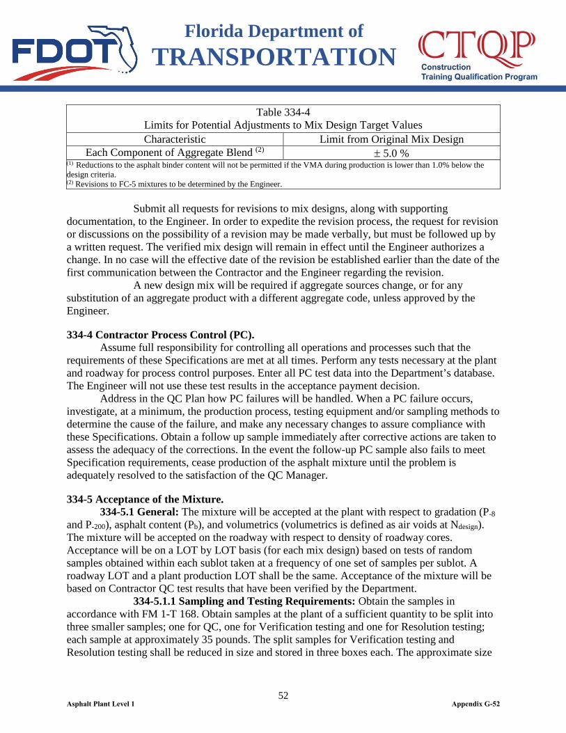
Florida Department of TRANSPORTATION
52
Table 334-4 Limits for Potential Adjustments to Mix Design Target Values Characteristic Limit from Original Mix Design
Each Component of Aggregate Blend (2) ± 5.0 % (1) Reductions to the asphalt binder content will not be permitted if the VMA during production is lower than 1.0% below the design criteria. (2) Revisions to FC-5 mixtures to be determined by the Engineer. Submit all requests for revisions to mix designs, along with supporting documentation, to the Engineer. In order to expedite the revision process, the request for revision or discussions on the possibility of a revision may be made verbally, but must be followed up by a written request. The verified mix design will remain in effect until the Engineer authorizes a change. In no case will the effective date of the revision be established earlier than the date of the first communication between the Contractor and the Engineer regarding the revision. A new design mix will be required if aggregate sources change, or for any substitution of an aggregate product with a different aggregate code, unless approved by the Engineer.
334-4 Contractor Process Control (PC). Assume full responsibility for controlling all operations and processes such that the requirements of these Specifications are met at all times. Perform any tests necessary at the plant and roadway for process control purposes. Enter all PC test data into the Department’s database. The Engineer will not use these test results in the acceptance payment decision. Address in the QC Plan how PC failures will be handled. When a PC failure occurs, investigate, at a minimum, the production process, testing equipment and/or sampling methods to determine the cause of the failure, and make any necessary changes to assure compliance with these Specifications. Obtain a follow up sample immediately after corrective actions are taken to assess the adequacy of the corrections. In the event the follow-up PC sample also fails to meet Specification requirements, cease production of the asphalt mixture until the problem is adequately resolved to the satisfaction of the QC Manager.
334-5 Acceptance of the Mixture. 334-5.1 General: The mixture will be accepted at the plant with respect to gradation (P-8 and P-200), asphalt content (Pb), and volumetrics (volumetrics is defined as air voids at Ndesign). The mixture will be accepted on the roadway with respect to density of roadway cores. Acceptance will be on a LOT by LOT basis (for each mix design) based on tests of random samples obtained within each sublot taken at a frequency of one set of samples per sublot. A roadway LOT and a plant production LOT shall be the same. Acceptance of the mixture will be based on Contractor QC test results that have been verified by the Department. 334-5.1.1 Sampling and Testing Requirements: Obtain the samples in accordance with FM 1-T 168. Obtain samples at the plant of a sufficient quantity to be split into three smaller samples; one for QC, one for Verification testing and one for Resolution testing; each sample at approximately 35 pounds. The split samples for Verification testing and Resolution testing shall be reduced in size and stored in three boxes each. The approximate size
Asphalt Plant Level 1 Appendix G-52

Florida Department of TRANSPORTATION
53
of each box must be 12 inches x 8 inches x 4 inches. Provide, label and safely store sample boxes in a manner agreed upon by the Engineer for future testing. The asphalt content of the mixture will be determined in accordance with FM 5-563. The gradation of the recovered aggregate will be determined in accordance with FM 1-T 030. Volumetric testing will be in accordance with AASHTO T 312-12and FM 1-T 209. Prior to testing volumetric samples, condition the test-sized sample for one hour, plus or minus five minutes, at the target roadway compaction temperature in a shallow, flat pan, such that the mixture temperature at the end of the one hour conditioning period is within plus or minus 20°F of the roadway compaction temperature. Test for roadway density in accordance with FM 1-T 166. 334-5.1.2 Acceptance Testing Exceptions: When the total combined quantity of hot mix asphalt for the project, as indicated in the Plans for Type SP and Type FC mixtures only, is less than 2000 tons, the Engineer will accept the mix on the basis of visual inspection. The Engineer may require the Contractor to run process control tests for informational purposes, as defined in 334-4, or may run independent verification tests to determine the acceptability of the material. Density testing for acceptance will not be performed on widening strips or shoulders with a width of 5 feet or less, open-graded friction courses, variable thickness overbuild courses, leveling courses, any asphalt layer placed on subgrade (regardless of type), miscellaneous asphalt pavement, shared use paths, crossovers, or any course with a specified thickness less than 1 inch or a specified spread rate that converts to less than 1 inch as described in 334-1.4. Density testing for acceptance will not be performed on asphalt courses placed on bridge decks or approach slabs; compact these courses in static mode only per the requirements of 330-7.7. In addition, density testing for acceptance will not be performed on the following areas when they are less than 1,000 feet (continuous) in length: turning lanes, acceleration lanes, deceleration lanes, shoulders, parallel parking lanes or ramps. Do not perform density testing for acceptance in situations where the areas requiring density testing is less than 50 tons within a sublot. Density testing for acceptance will not be performed in intersections. The limits of the intersection will be from stop bar to stop bar for both the mainline and side streets. A random core location that occurs within the intersection shall be moved forward or backward from the intersection at the direction of the Engineer. Where density testing for acceptance is not required, compact these courses (with the exception of open-graded friction courses) in accordance with the rolling procedure (equipment and pattern) as approved by the Engineer or with Standard Rolling Procedure as specified in 330-7.2. In the event that the rolling procedure deviates from the procedure approved by the Engineer, or the Standard Rolling Procedure, placement of the mix shall be stopped. The density pay factor (as defined in 334-8.2) for areas not requiring density testing for acceptance will be paid at the same density pay factor as for the areas requiring density testing within the same LOT. If the entire LOT does not require density testing for acceptance, the LOT will be paid at a density pay factor of 1.00.
Asphalt Plant Level 1 Appendix G-53
Florida Department of TRANSPORTATION
54
334-5.2 Full LOTs: Each LOT will be defined (as selected by the Contractor prior to the start of the LOT) as either (1) 2,000 tons, with each LOT subdivided into four equal sublots of 500 tons each, or (2) 4,000 tons, with each LOT subdivided into four equal sublots of 1,000 tons each. As an exception to this, the initial LOT of all new mix designs shall be defined as 2,000 tons, subdivided into four equal sublots of 500 tons each. Before the beginning of a LOT, the Engineer will develop a random sampling plan for each sublot and direct the Contractor on sample points, based on tonnage, for each sublot during construction. 334-5.3 Partial LOTs: A partial LOT is defined as a LOT size that is less than a full LOT. A partial LOT may occur due to the following: l. The completion of a given mix type or mix design on a project. 2. Closure of the LOT due to time. LOTs will be closed 30 calendar days after the start of the LOT. Time periods other than 30 calendar days may be used if agreed to by both the Engineer and the Contractor, but under no circumstances shall the LOT be left open longer than 60 days. 3. A LOT is terminated per 334-5.4.4. All partial LOTs will be evaluated based on the number of tests available, and will not be redefined. If a LOT is closed before the first plant random sample is obtained, then the LOT will be visually accepted by the Engineer and the LOT pay factor will be 1.00. 334-5.4 QC Sampling and Testing: Obtain all samples randomly as directed by the Engineer. Should the Engineer determine that the QC requirements are not being met or that unsatisfactory results are being obtained, or should any instances of falsification of test data occur, approval of the Contractor’s QC Plan will be suspended and production will be stopped. 334-5.4.1 Lost or Missing Verification/Resolution Samples: In the event that any of the Verification and/or Resolution samples that are in the custody of the Contractor are lost, damaged, destroyed, or are otherwise unavailable for testing, the minimum possible pay factor for each quality characteristic as described in 334-8.2 will be applied to the entire LOT in question, unless called for otherwise by the Engineer. Specifically, if the LOT in question has more than two sublots, the pay factor for each quality characteristic will be 0.55. If the LOT has two or less sublots, the pay factor for each quality characteristic will be 0.80. In either event, the material in question will also be evaluated in accordance with 334-5.9.5. If any of the Verification and/or Resolution samples that are in the custody of the Department are lost, damaged, destroyed or are otherwise unavailable for testing, the corresponding QC test result will be considered verified, and payment will be based upon the Contractor’s data. 334-5.4.2 Plant Sampling and Testing Requirements: Obtain one random sample of mix per sublot in accordance with 334-5.1.1 as directed by the Engineer. Test the QC split sample for gradation, asphalt binder content and volumetrics in accordance with 334-5.1.1. Complete all QC testing within one working day from the time the samples were obtained. 334-5.4.3 Roadway Sampling and Testing Requirements: Obtain five 6 inch diameter roadway cores within 24 hours of placement at random locations as directed by the Engineer within each sublot. Test these QC samples for density (Gmb) in accordance with 334-5.1.1. Obtain a minimum of three cores per sublot at random locations as identified by the
Asphalt Plant Level 1 Appendix G-54
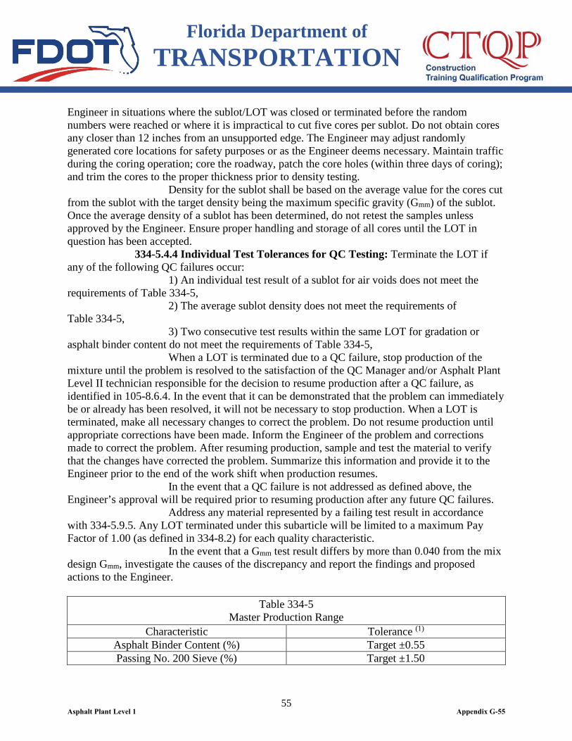
Florida Department of TRANSPORTATION
55
Engineer in situations where the sublot/LOT was closed or terminated before the random numbers were reached or where it is impractical to cut five cores per sublot. Do not obtain cores any closer than 12 inches from an unsupported edge. The Engineer may adjust randomly generated core locations for safety purposes or as the Engineer deems necessary. Maintain traffic during the coring operation; core the roadway, patch the core holes (within three days of coring); and trim the cores to the proper thickness prior to density testing. Density for the sublot shall be based on the average value for the cores cut from the sublot with the target density being the maximum specific gravity (Gmm) of the sublot. Once the average density of a sublot has been determined, do not retest the samples unless approved by the Engineer. Ensure proper handling and storage of all cores until the LOT in question has been accepted. 334-5.4.4 Individual Test Tolerances for QC Testing: Terminate the LOT if any of the following QC failures occur: 1) An individual test result of a sublot for air voids does not meet the requirements of Table 334-5, 2) The average sublot density does not meet the requirements of Table 334-5, 3) Two consecutive test results within the same LOT for gradation or asphalt binder content do not meet the requirements of Table 334-5, When a LOT is terminated due to a QC failure, stop production of the mixture until the problem is resolved to the satisfaction of the QC Manager and/or Asphalt Plant Level II technician responsible for the decision to resume production after a QC failure, as identified in 105-8.6.4. In the event that it can be demonstrated that the problem can immediately be or already has been resolved, it will not be necessary to stop production. When a LOT is terminated, make all necessary changes to correct the problem. Do not resume production until appropriate corrections have been made. Inform the Engineer of the problem and corrections made to correct the problem. After resuming production, sample and test the material to verify that the changes have corrected the problem. Summarize this information and provide it to the Engineer prior to the end of the work shift when production resumes. In the event that a QC failure is not addressed as defined above, the Engineer’s approval will be required prior to resuming production after any future QC failures. Address any material represented by a failing test result in accordance with 334-5.9.5. Any LOT terminated under this subarticle will be limited to a maximum Pay Factor of 1.00 (as defined in 334-8.2) for each quality characteristic. In the event that a Gmm test result differs by more than 0.040 from the mix design Gmm, investigate the causes of the discrepancy and report the findings and proposed actions to the Engineer.
Table 334-5 Master Production Range
Characteristic Tolerance (1) Asphalt Binder Content (%) Target ±0.55 Passing No. 200 Sieve (%) Target ±1.50
Asphalt Plant Level 1 Appendix G-55
Florida Department of TRANSPORTATION
56
Table 334-5 Master Production Range
Characteristic Tolerance (1) Air Voids (%) Fine Graded 2.30 – 6.00 Density (minimum % Gmm) 90.00
(1) Tolerances for sample size of n = 1 from the verified mix design (2) Based on an average of 5 randomly located cores 334-5.5 Verification Testing: In order to determine the validity of the Contractor’s QC test results prior to their use in the Acceptance decision, the Engineer will run verification tests. 334-5.5.1 Plant Testing: At the completion of each LOT, the Engineer will test a minimum of one Verification split sample randomly selected from the LOT. Results of the testing and analysis for the LOT will be made available to the Contractor within one working day from the time the LOT is completed. Verification samples shall be reheated at the target roadway compaction temperature for 1-1/2 hours, plus or minus 5 minutes, reduced to the appropriate testing size, and conditioned and tested as described in 334-5.1.1. In lieu of the 1-1/2 hours reheating procedure, the mixture may be reheated to within plus or minus 20°F of the roadway compaction temperature using a microwave oven. Stir the mixture as necessary during the reheating process to maintain temperature uniformity. Subsequently, condition and test the mixture as described in 334-5.1.1. The Verification test results will be compared with the QC test results based on the between-laboratory precision values shown in Table 334-6.
Table 334-6 Between-Laboratory Precision Values
Property Maximum Difference Gmm 0.016
Gmb (gyratory compacted samples) 0.022 Gmb (roadway cores) 0.015
Pb 0.44% P-200 FM 1-T 030 (Figure 2) P-8 FM 1-T 030 (Figure 2)
If all of the specified mix characteristics compare favorably, then the LOT will be accepted, with payment based on the Contractor’s QC test data for the LOT. If any of the results do not compare favorably, then the Resolution samples from the LOT will be sent to the Resolution laboratory for testing, as described in 334-5.6. 334-5.5.2 Roadway Testing: At the completion of each LOT, the Engineer will determine the density (Gmb) of each core (previously tested by QC) as described in 334-5.1.1 from the same sublot as the plant samples. For situations where roadway density is not required for the random sublot chosen, then another sublot shall be randomly chosen for roadway density
Asphalt Plant Level 1 Appendix G-56
Florida Department of TRANSPORTATION
57
cores only. Results of the testing and analysis for the LOT will be made available to the Contractor within one working day from the time the LOT is completed. The individual Verification test results will be compared with individual QC test results by the Engineer based on the between-laboratory precision values given in Table 334-6. If each of the core test results compare favorably, then the LOT will be accepted with respect to density, with payment based on the Contractor’s QC test data for the LOT. If any of the results do not compare favorably, then the core samples from the LOT will be sent to the Resolution laboratory for testing as specified in 334-5.6. 334-5.6 Resolution System: 334-5.6.1 Plant Samples: In the event of an unfavorable comparison between the Contractor’s QC test results and the Engineer’s Verification test results on any of the properties identified in Table 334-6, the Resolution laboratory will test all of the split samples from the LOT for only the property (or properties) in question. Resolution samples shall be reheated at the target roadway compaction temperature for 1-1/2 hours, plus or minus 5 minutes, reduced to the appropriate testing size, and conditioned and tested as described in 334-5.1.1. In lieu of the 1-1/2 hours reheating procedure, the mixture may be reheated to within plus or minus 20°F of the roadway compaction temperature using a microwave oven. Stir the mixture as necessary during the reheating process to maintain temperature uniformity. Subsequently, condition and test the mixture as described in 334-5.1.1. 334-5.6.2 Roadway Samples: In the event of an unfavorable comparison between the Contractor’s QC test data and the Engineer’s Verification test data on the density results, the Resolution laboratory will test all of the cores from the LOT. Testing will be as described in 334-5.1.1. Any damaged roadway cores will not be included in the evaluation; replace damaged cores with additional cores at the direction of the Engineer. 334-5.6.3 Resolution Determination: The Resolution test results (for the property or properties in question) will be compared with the QC test results based on the between-laboratory precision values shown in Table 334-6. If the Resolution laboratory results compare favorably with all of the QC results, then acceptance and payment for the LOT will be based on the QC results, and the Department will bear the costs associated with Resolution testing. No additional compensation, either monetary or time, will be made for the impacts of any such testing. If the Resolution laboratory results do not compare favorably with all of the QC results, then acceptance and payment for the LOT will be based on the Resolution test data for the LOT, and the costs of the Resolution testing will be deducted from monthly estimates. No additional time will be granted for the impacts of any such testing. In addition, in the event that the application of the Resolution test data results in a failure to meet the requirements of Table 334-5, address any material represented by the failing test result in accordance with 334-5.9.5. In the event of an unfavorable comparison between the Resolution test results and QC test results, make the necessary adjustments to assure that future comparisons are favorable.
Asphalt Plant Level 1 Appendix G-57

Florida Department of TRANSPORTATION
58
334-5.7 Independent Verification (IV) Testing: 334-5.7.1 Plant: The Contractor shall provide sample boxes and take samples as directed by the Engineer for IV testing. Obtain enough material for three complete sets of tests (two samples for IV testing by the Engineer and one sample for testing by the Contractor). If agreed upon by both the Engineer and the Contractor, only one sample for IV testing by the Engineer may be obtained. IV samples will be reheated at the target roadway compaction temperature for 1-1/2 hours, plus or minus 5 minutes, reduced to the appropriate testing size, and conditioned and tested as described in 334-5.1.1. The Contractor’s split sample, if tested immediately after sampling, shall be reduced to the appropriate testing size, and conditioned and tested as described in 334-5.1.1. If the Contractor’s sample is not tested immediately after sampling, then the sample shall be reheated at the target roadway compaction temperature for 1-1/2 hours, plus or minus 5 minutes, reduced to the appropriate testing size, and conditioned and tested as described in 334-5.1.1. For the IV and Contractor's samples, in lieu of the 1-1/2 hours reheating procedure, the mixture may be reheated to within plus or minus 20°F of the roadway compaction temperature using a microwave oven. Stir the mixture as necessary during the reheating process to maintain temperature uniformity. Subsequently, condition and test the mixture as described in 334-5.1.1. The Contractor’s test results shall be provided to the Engineer within one working day from the time the sample was obtained. If any of the IV test results do not meet the requirements of Table 334-5, then a comparison of the IV test results and the Contractor’s test results, if available, will be made. If a comparison of the IV test results and the Contractor’s test results meets the precision values of Table 334-6 for the material properties in question, or if the Contractor’s test results are not available, then the IV test results are considered verified and the Contractor shall cease production of the asphalt mixture until the problem is adequately resolved (to the satisfaction of the Engineer), unless it can be demonstrated to the satisfaction of the Engineer that the problem can immediately be (or already has been) resolved. Address any material represented by the failing test results in accordance with 334-5.9.5. If a comparison of the IV test results and the Contractor’s test results does not meet the precision values of Table 334-6 for the material properties in question, then the second IV sample shall be tested by the Engineer for the material properties in question. If a comparison between the first and second IV test results does not meet the precision values of Table 334-6 for the material properties in question, then the first IV test results are considered unverified for the material properties in question and no action shall be taken. If a comparison between the first and second IV test results meets the precision values of Table 334-6 for the material properties in question, then the first IV sample is considered verified and the Contractor shall cease production of the asphalt mixture until the problem is adequately resolved (to the satisfaction of the Engineer), unless it can be demonstrated to the satisfaction of the Engineer that the problem can immediately be (or already has been) resolved. Address any material represented by the failing test results in accordance with 334-5.9.5. The Engineer has the option to use the IV sample for comparison testing as specified in 334-6.
Asphalt Plant Level 1 Appendix G-58
Florida Department of TRANSPORTATION
59
334-5.7.2 Roadway: Obtain five 6 inch diameter roadway cores within 24 hours of placement, as directed by the Engineer, for IV testing. In situations where it is impractical to cut five cores per sublot, obtain a minimum of three cores per sublot at random locations, as identified by the Engineer. These independent cores will be obtained from the same LOTs and sublots as the Independent Verification Plant samples, or as directed by the Engineer. The density of these cores will be obtained as described in 334-5.1.1. If the average of the results for the sublot does not meet the requirements of Table 334-5 for density, then a comparison of the IV Gmm test results and the Contractor’s Gmm test results, if available, will be made in accordance with the procedure provided in 334-5.7.1. Address any material represented by the failing test results in accordance with 334-5.9.5. 334-5.8 Surface Tolerance: The asphalt mixture will be accepted on the roadway with respect to surface tolerance in accordance with the applicable requirements of 330-9. 334-5.9 Minimum Acceptable Quality Levels: 334-5.9.1 CPFs Below 0.90: In the event that an individual pay factor for any quality characteristic of a LOT falls below 0.90, take steps to correct the situation and report the actions to the Engineer. In the event that the pay factor for the same quality characteristic for two consecutive LOTs is below 0.90, cease production of the asphalt mixture until the problem is adequately resolved (to the satisfaction of the Engineer), unless it can be demonstrated to the satisfaction of the Engineer that the problem can immediately be (or already has been) resolved. Actions taken must be approved by the Engineer before production resumes. 334-5.9.2 CPFs Less Than 0.90 and Greater Than or Equal to 0.80: If the composite pay factor for the LOT is less than 0.90 and greater than or equal to 0.80, cease production of the asphalt mixture until the problem is adequately resolved (to the satisfaction of the Engineer), unless it can be demonstrated to the satisfaction of the Engineer that the problem can immediately be (or already has been) resolved. Actions taken must be approved by the Engineer before production resumes. 334-5.9.3 CPFs Less Than 0.80 and Greater Than or Equal to 0.75: If the CPF for the LOT is less than 0.80 and greater than or equal to 0.75, address the defective material in accordance with 334-5.9.5. 334-5.9.4 CPFs Less Than 0.75: If the CPF for the LOT is less than 0.75, remove and replace the defective LOT at no cost to the Department, or as approved by the Engineer. 334-5.9.5 Defective Material: Assume responsibility for removing and replacing all defective material placed on the project, at no cost to the Department. As an exception to the above and upon approval of the Engineer, obtain an engineering analysis by an independent laboratory (as approved by the Engineer) to determine the disposition of the material. The engineering analysis must be signed and sealed by a Professional Engineer licensed in the State of Florida. The Engineer may determine that an engineering analysis is not necessary or may perform an engineering analysis to determine the disposition of the material. Any material that remains in place will be accepted with a CPF as determined by 334-8, or as determined by the Engineer.
Asphalt Plant Level 1 Appendix G-59
Florida Department of TRANSPORTATION
60
If the defective material is due to a gradation, asphalt binder content or density failure, upon the approval of the Engineer the Contractor may perform delineation tests on roadway cores in lieu of an engineering analysis to determine the limits of the defective material that may require removal and replacement. Prior to any delineation testing, all sampling locations shall be approved by the Engineer. All delineation sampling and testing shall be monitored and verified by the Engineer. For materials that are defective due to air voids, an engineering analysis is required. When evaluating defective material by engineering analysis or delineation testing, at a minimum, evaluate all material located between passing QC, PC or IV test results. Exceptions to this requirement shall be approved by the Engineer.
334-6 Comparison Testing. At the start of the project (unless waived by the Engineer) and at other times as determined necessary by the Engineer, provide split samples for comparison testing with the Engineer. The purpose of these tests is to verify that the testing equipment is functioning properly and that the testing procedures are being performed correctly. In the event that the Engineer determines that there is a problem with the Contractor’s testing equipment and/or testing procedures, immediately correct the problem to the Engineer’s satisfaction. In the event that the problem is not immediately corrected, cease production of the asphalt mixture until the problem is adequately resolved to the satisfaction of the Engineer. If so agreed to by both the Contractor and the Engineer, the split sample used for comparison testing may also be used for the QC sample. The split sample used for comparison testing must also meet the requirements for IV testing described in 334-5.7.
334-7 Method of Measurement. For the work specified under this Section (including the pertinent provisions of Sections 320 and 330), the quantity to be paid for will be the weight of the mixture, in tons. The pay quantity will be based on the project average spread rate, excluding overbuild, limited to a maximum of 105% of the spread rate determined in accordance with 334-1.4 or as set by the Engineer. The project average spread rate is calculated by totaling the arithmetic mean of the average daily spread rate values for each layer. The bid price for the asphalt mix will include the cost of the liquid asphalt and the tack coat application as directed in 300-8. There will be no separate payment or unit price adjustment for the asphalt binder material in the asphalt mix. For the calculation of unit price adjustments of bituminous material, the average asphalt content will be based on the percentage specified in 9-2.1.2. The weight will be determined as provided in 320-3.2 (including the provisions for the automatic recordation system). Prepare a Certification of Quantities, using the Department’s current approved form, for the certified Superpave asphalt concrete pay item. Submit this certification to the Engineer no later than Twelve O’clock noon Monday after the estimate cut-off or as directed by the Engineer, based on the quantity of asphalt produced and accepted on the roadway per Contract. The certification must include the Contract Number, FPID Number, Certification Number, Certification Date, period represented by Certification and the tons produced for each asphalt pay item.
Asphalt Plant Level 1 Appendix G-60
Florida Department of TRANSPORTATION
61
334-8 Basis of Payment. 334-8.1 General: Price and payment will be full compensation for all the work specified under this Section (including the applicable requirements of Sections 320 and 330). For materials accepted in accordance with 334-5, based upon the quality of the material, a pay adjustment will be applied to the bid price of the material as determined on a LOT by LOT basis. The pay adjustment will be assessed by calculating a Pay Factor for the following individual quality characteristics: pavement density, air voids, asphalt binder content, and the percentage passing the No. 200 and No. 8 sieves. The pay adjustment will be computed by multiplying a CPF for the LOT by the bid price per ton. Perform all calculations using the latest version of the Department’s Asphalt Plant Worksheet. 334-8.2 Pay Factors: 334-8.2.1 Partial LOTs: For Partial LOTs where no random sample is obtained due to insufficient tonnage, a CPF of 1.00 shall be applied. 334-8.2.2 Two or Less Sublot Test Results: In the event that two or less sublot test results are available for a LOT, Pay Factors will be determined based on the Small Quantity Pay Table. The Small Quantity Pay Table and Pay Factor calculations are determined in accordance with the instructions contained within the Department’s Asphalt Plant Worksheet. 334-8.2.3 Three or More Sublot Test Results: When three or more sublot test results are available for a LOT, the variability-unknown, standard deviation method will be used to determine the estimated percentage of the LOT that is within the specification limits shown in Table 334-7. The Percent Within Limits (PWL) is determined in accordance with the instructions contained within the Department’s Asphalt Plant Worksheet.
Table 334-7 Specification Limits
Quality Characteristic Specification Limits Passing No. 8 sieve (%) Target ± 3.1
Passing No. 200 sieve (%) Target ± 1.0 Asphalt Content (%) Target ± 0.40
Air Voids (%) 4.00 ± 1.20 Density (% of Gmm): 93.00 + 2.00, - 1.20 (1)
Note (1): If the Engineer (or Contract Documents) limits compaction to the static mode only, or for all one-inch thick lifts, compaction shall be in the static mode. No vibratory mode in the vertical direction will be allowed. Other vibratory modes will be allowed, if approved by the Engineer. In either case, the specification limits will be as follows: 92.00 + 3.00, -1.20%of Gmm. No additional compensation, cost or time, shall be made. 334-8.2.3.1 Pay Factors (PF): Pay Factors will be calculated by using the following equation: Pay Factor = (55 + 0.5 x PWL) / 100 The PWL is determined in accordance with the instructions contained within the Department’s Asphalt Plant Worksheet.
Asphalt Plant Level 1 Appendix G-61
Florida Department of TRANSPORTATION
62
334-8.3 Composite Pay Factor (CPF): A CPF for the LOT will be calculated based on the individual PFs with the following weighting applied: 35% Density (D), 25% Air Voids (Va), 25% asphalt binder content (Pb), 10% Passing No. 200 (P-200) and 5% Passing No. 8 (P-8). Calculate the CPF by using the following formula: CPF = [(0.350 x PF D) + (0.250 x PF Va) + (0.250 x PF Pb) + (0.100 x PF P-200) + (0.050 x PF P-8)] Where the PF for each quality characteristic is determined in either 334-8.2.2 or 334-8.2.3, depending on the number of sublot tests. Note that the number after each multiplication will be rounded to the nearest 0.01. The pay adjustment shall be computed by multiplying the CPF for the LOT by the bid price per ton. 334-8.4 Payment: Payment will be made under:
Item No. 334- 1- Superpave Asphaltic Concrete - per ton. ‘
Asphalt Plant Level 1 Appendix G-62
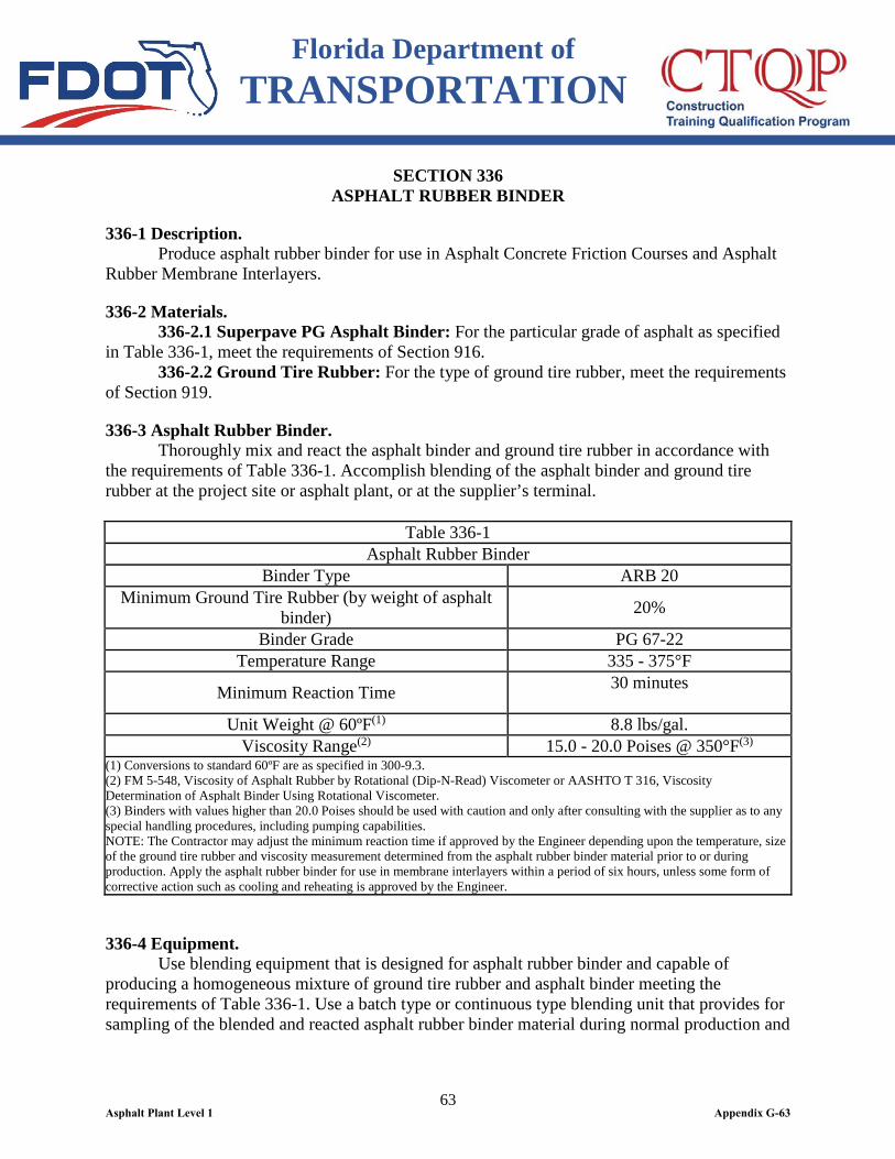
Florida Department of TRANSPORTATION
63
SECTION 336 ASPHALT RUBBER BINDER
336-1 Description. Produce asphalt rubber binder for use in Asphalt Concrete Friction Courses and Asphalt Rubber Membrane Interlayers.
336-2 Materials. 336-2.1 Superpave PG Asphalt Binder: For the particular grade of asphalt as specified in Table 336-1, meet the requirements of Section 916. 336-2.2 Ground Tire Rubber: For the type of ground tire rubber, meet the requirements of Section 919.
336-3 Asphalt Rubber Binder. Thoroughly mix and react the asphalt binder and ground tire rubber in accordance with the requirements of Table 336-1. Accomplish blending of the asphalt binder and ground tire rubber at the project site or asphalt plant, or at the supplier’s terminal.
Table 336-1 Asphalt Rubber Binder
Binder Type ARB 20 Minimum Ground Tire Rubber (by weight of asphalt
binder) 20%
Binder Grade PG 67-22 Temperature Range 335 - 375°F
Minimum Reaction Time 30 minutes
Unit Weight @ 60ºF(1) 8.8 lbs/gal. Viscosity Range(2) 15.0 - 20.0 Poises @ 350°F(3)
(1) Conversions to standard 60ºF are as specified in 300-9.3. (2) FM 5-548, Viscosity of Asphalt Rubber by Rotational (Dip-N-Read) Viscometer or AASHTO T 316, Viscosity Determination of Asphalt Binder Using Rotational Viscometer. (3) Binders with values higher than 20.0 Poises should be used with caution and only after consulting with the supplier as to any special handling procedures, including pumping capabilities. NOTE: The Contractor may adjust the minimum reaction time if approved by the Engineer depending upon the temperature, size of the ground tire rubber and viscosity measurement determined from the asphalt rubber binder material prior to or during production. Apply the asphalt rubber binder for use in membrane interlayers within a period of six hours, unless some form of corrective action such as cooling and reheating is approved by the Engineer.
336-4 Equipment. Use blending equipment that is designed for asphalt rubber binder and capable of producing a homogeneous mixture of ground tire rubber and asphalt binder meeting the requirements of Table 336-1. Use a batch type or continuous type blending unit that provides for sampling of the blended and reacted asphalt rubber binder material during normal production and
Asphalt Plant Level 1 Appendix G-63
Florida Department of TRANSPORTATION
64
provides for accurate proportioning of the asphalt binder and ground tire rubber either by weight or volume. In order to meet specification requirements, keep the asphalt rubber uniformly blended while in storage. Equip storage tanks with a sampling device.
336-5 Testing of Asphalt Rubber Binder: 336-5.1 Quality Control Requirements: Test the asphalt rubber binder for the viscosity requirement of Table 336-1 at the following frequencies and situations: 1. One per batch (for batch blending) or two per day (for continuous blending) during blending at the project site or asphalt plant, or the supplier’s terminal. 2. Each load delivered to the project site or asphalt plant when blended at the supplier’s terminal. 3. Beginning of each day from the storage tank when storing the asphalt rubber binder at the project site or asphalt plant, or the supplier’s terminal, obtain the sample for testing from the discharge piping exiting the storage tank. Obtain the viscosity testing equipment specified in FM 5-548 and make it available to the Engineer for verification purposes at the project site or asphalt plant and supplier’s terminal. 336-5.1.1 Action at Project Site or Asphalt Plant: If the asphalt rubber binder does not meet the minimum viscosity requirement at the project site or asphalt plant, stop use of the asphalt rubber binder in the Asphalt Concrete Friction Course and Asphalt Rubber Membrane Interlayer, notify the Engineer, and make the appropriate adjustments as necessary to meet the requirements of Table 336-1 in order to: (1) correct the viscosity of the blended material and (2) correct the blending operation. In the event that the corrective actions taken fail to correct the problem, or the material consistently fails to meet the minimum viscosity requirement, do not use the asphalt rubber binder in storage, and where applicable, stop all asphalt rubber blending operations at the project site or asphalt plant and solve the problem. Do not use asphalt rubber binder with low viscosity in mix and interlayer construction, or resume blending operations at the project site or asphalt plant until the Engineer grants approval. The Engineer may require that any mix and interlayer placed with low viscosity asphalt rubber binder be evaluated in accordance with 334-5.9.5. In the event that the viscosity of the asphalt rubber binder increases to the extent that plant production or paving operations of the mix are adversely affected (i.e. density or texture problems occur), stop plant operations and resolve the problem to the Engineer’s satisfaction. 336-5.1.2 Action at Supplier’s Terminal: If the asphalt rubber binder does not meet the minimum viscosity requirement at the supplier’s terminal, stop shipment and blending of asphalt rubber binder, and make the appropriate adjustments as necessary to meet the requirements of Table 336-1 in order to (1) correct the viscosity of the blended material in the tank, and (2) correct the blending operation. Resume shipment and blending of asphalt rubber binder when a retest indicates the viscosity meets Specifications. Document actions taken in the Quality Control records. 336-5.2 Verification Requirements: The Engineer will test the asphalt rubber in accordance with FM 5-548 or AASHTO T 316 randomly on an as needed basis at the project site or asphalt plant, or the supplier’s terminal to ensure conformance with the minimum viscosity
Asphalt Plant Level 1 Appendix G-64
Florida Department of TRANSPORTATION
65
requirement as specified in Table 336-1. 336-5.2.1 Action at Project Site or Asphalt Plant: If the asphalt rubber binder does not meet the viscosity requirements at the project site or asphalt plant, stop use of asphalt rubber binder. Do not use asphalt rubber binder with a viscosity outside of the specified range in mix and interlayer construction until corrective actions, as necessary to meet the requirements of Table 336-1, have been made, verified by passing test results, and the Engineer grants approval. The Engineer may require that any mix and interlayer placed with an asphalt rubber binder with a viscosity outside of the specified range be evaluated in accordance with 334-5.9.5. In the event that the viscosity of the asphalt rubber binder adversely affects plant production or paving operations, stop plant and paving operations and resolve the problem to the Engineer’s satisfaction. 336-5.2.2 Action at Supplier’s Terminal: If the asphalt rubber binder does not meet the viscosity requirements at the supplier’s terminal, stop shipment and blending of asphalt rubber binder until corrective actions are made to meet the requirements of Table 336-1. 336-5.3 Asphalt Rubber Binder Blending Quality Control Records: Maintain adequate Quality Control records for the Engineer’s review of all blending activities. The Quality Control records shall include at a minimum the following information (for each batch of asphalt rubber binder produced): asphalt rubber binder type, asphalt rubber binder batch quantity, asphalt binder supplier (including APL number and LOT), asphalt binder quantity in gallons, ground tire rubber supplier (including APL number and LOT), ground tire rubber quantity in pounds, individual quantities of asphalt rubber binder shipped, financial project number, shipping date, customer name, delivery location, and viscosity test results. 336-5.3.1 Additional Records for Blending at Project Site or Asphalt Plant: Monitor the ground tire rubber content in the asphalt rubber binder on a daily basis based on one of the following methods: 1. Record the weight of the ground tire rubber used and the number of gallons of asphalt rubber binder produced. Calculate the percentage of rubber used and confirm that the minimum rubber requirements are met. Use the unit weight per gallon for the various types of asphalt rubber binder shown in Table 336-1 for the calculations. 2. Record the weight of the ground tire rubber used and the number of gallons of asphalt binder used. Calculate the percentage of rubber used and confirm that the minimum rubber requirements are met.
336-6 Use of Excess Asphalt Rubber. The Contractor may use excess asphalt rubber in other asphalt concrete mixes requiring the use of a PG 67-22 binder by blending with straight PG 67-22 binder so that the total amount of ground tire rubber in the binder is less than 2.0%. The Contractor may use excess asphalt rubber in asphalt concrete mixtures requiring the use of a recycling agent in a recycled mixture by blending with a recycling agent in such proportions that the total amount of ground tire rubber in the recycling agent is less than 1.0%.
336-7 Certification Requirements for Blending at Suppliers Terminal: Where blending the asphalt rubber binder at the supplier’s terminal, the supplier shall furnish certification on the bill of lading for each load delivered to the project site or asphalt
Asphalt Plant Level 1 Appendix G-65
Florida Department of TRANSPORTATION
66
plant that includes: the quantity of asphalt rubber binder, the asphalt rubber binder type, the customer name, the delivery location, and a statement that the asphalt rubber binder has been produced in accordance with and meets the requirements of Section 336. In addition, include with the certification, copies of the certifications for the asphalt binder and ground tire rubber as specified in 916-1.3 and 919-6, respectively.
336-8 Basis of Payment. Payment for asphalt rubber binder will be included in Sections 337 and 341, as appropriate.
SECTION 337 ASPHALT CONCRETE FRICTION COURSES
337-1 Description. Construct an asphalt concrete friction course pavement with the type of mixture specified in the Contract Documents, or when offered as alternates, as selected. This Section specifies mixes designated as FC-5, FC-9.5, and FC-12.5. Meet the plant and equipment requirements of Section 320, as modified herein. Meet the general construction requirements of Section 330, as modified herein.
337-2 Materials. 337-2.1 General Requirements: Meet the requirements specified in Division III as modified herein. The Engineer will base continuing approval of material sources on field performance. Warm mix technologies (additives, foaming techniques, etc.) listed on the Department’s website may be used in the production of the mix. The URL for obtaining this information, if available, is: http://www.dot.state.fl.us/statematerialsoffice/quality/programs/warmmixasphalt/index.shtm. 337-2.2 Asphalt Binder: Meet the requirements of Section 916, and any additional requirements or modifications specified herein for the various mixtures. For projects with a total quantity of FC-5, FC-9.5, or FC-12.5 less than 500 tons, the Contractor may elect to substitute a PG 76-22 (PMA) or PG 82-22 (PMA) for the PG 76-22 (ARB), meeting the requirements of Section 916. 337-2.3 Coarse Aggregate: Meet the requirements of Section 901, and any additional requirements or modifications specified herein for the various mixtures. 337-2.4 Fine Aggregate: Meet the requirements of Section 902, and any additional requirements or modifications specified herein for the various mixtures. 337-2.5 Hydrated Lime: Meet the requirements of AASHTO M 303-89 (2010), Type 1. Provide certified test results for each shipment of hydrated lime indicating compliance with the specifications. 337-2.6 Liquid Anti-strip Additive: Meet the requirements of 916-3 and be listed on the Department’s Approved Product List (APL). 337-2.7 Fiber Stabilizing Additive (Required for FC-5 only): Use either a mineral or
Asphalt Plant Level 1 Appendix G-66

Florida Department of TRANSPORTATION
67
cellulose fiber stabilizing additive. Meet the following requirements: 337-2.7.1 Mineral Fibers: Use mineral fibers (made from virgin basalt, diabase, or slag) treated with a cationic sizing agent to enhance the disbursement of the fiber, as well as to increase adhesion of the fiber surface to the bitumen. Meet the following requirements for physical properties: 1. Size Analysis Average fiber length: 0.25 inch (maximum) Average fiber thickness: 0.0002 inch (maximum) 2. Shot Content (ASTM C612-10) Percent passing No. 60 Sieve: 90 - 100 Percent passing No. 230 Sieve: 65 - 100 Provide certified test results for each batch of fiber material indicating compliance with the above tests. 337-2.7.2 Cellulose Fibers: Use cellulose fibers meeting the following requirements: 1. Fiber length: 0.25 inch (maximum) 2. Sieve Analysis a. Alpine Sieve Method Percent passing No. 100 sieve: 60-80 b. Ro-Tap Sieve Method Percent passing No. 20 sieve: 80-95 Percent passing No. 40 sieve: 45-85 Percent passing No. 100 sieve: 5-40 3. Ash Content: 18% non-volatiles (plus or minus 5%) 4. pH: 7.5 (plus or minus 1.0) 5. Oil Absorption: 5.0% (plus or minus 1.0) (times fiber weight) 6. Moisture Content: 5.0% by weight (maximum) Provide certified test results for each batch of fiber material indicating compliance with the above tests.
337-3 General Composition of Mixes. 337-3.1 General: Use a bituminous mixture composed of aggregate (coarse, fine, or a mixture thereof), asphalt binder, and in some cases, fibers and/or hydrated lime. Size, uniformly grade and combine the aggregate fractions in such proportions that the resulting mix meets the requirements of this Section. 337-3.2 Specific Component Requirements by Mix: 337-3.2.1 FC-5: 337-3.2.1.1 Aggregates: Use an aggregate blend which consists of either 100% crushed granite, 100% crushed Oolitic limestone or 100% other crushed materials (as approved by the Engineer for friction courses per Rule 14-103.005, Florida Administrative Code). Crushed limestone from the Oolitic formation may be used if it contains a minimum of 12% silica material as determined by FM 5-510 and the Engineer grants approval of the source prior to its use.
Asphalt Plant Level 1 Appendix G-67
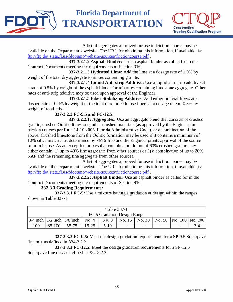
Florida Department of TRANSPORTATION
68
A list of aggregates approved for use in friction course may be available on the Department’s website. The URL for obtaining this information, if available, is: ftp://ftp.dot.state.fl.us/fdot/smo/website/sources/frictioncourse.pdf . 337-3.2.1.2 Asphalt Binder: Use an asphalt binder as called for in the Contract Documents meeting the requirements of Section 916. 337-3.2.1.3 Hydrated Lime: Add the lime at a dosage rate of 1.0% by weight of the total dry aggregate to mixes containing granite. 337-3.2.1.4 Liquid Anti-strip Additive: Use a liquid anti-strip additive at a rate of 0.5% by weight of the asphalt binder for mixtures containing limestone aggregate. Other rates of anti-strip additive may be used upon approval of the Engineer. 337-3.2.1.5 Fiber Stabilizing Additive: Add either mineral fibers at a dosage rate of 0.4% by weight of the total mix, or cellulose fibers at a dosage rate of 0.3% by weight of total mix. 337-3.2.2 FC-9.5 and FC-12.5: 337-3.2.2.1: Aggregates: Use an aggregate blend that consists of crushed granite, crushed Oolitic limestone, other crushed materials (as approved by the Engineer for friction courses per Rule 14-103.005, Florida Administrative Code), or a combination of the above. Crushed limestone from the Oolitic formation may be used if it contains a minimum of 12% silica material as determined by FM 5-510 and the Engineer grants approval of the source prior to its use. As an exception, mixes that contain a minimum of 60% crushed granite may either contain: 1) up to 40% fine aggregate from other sources or 2) a combination of up to 20% RAP and the remaining fine aggregate from other sources. A list of aggregates approved for use in friction course may be available on the Department’s website. The URL for obtaining this information, if available, is: ftp://ftp.dot.state.fl.us/fdot/smo/website/sources/frictioncourse.pdf . 337-3.2.2.2: Asphalt Binder: Use an asphalt binder as called for in the Contract Documents meeting the requirements of Section 916. 337-3.3 Grading Requirements: 337-3.3.1 FC-5: Use a mixture having a gradation at design within the ranges shown in Table 337-1.
Table 337-1 FC-5 Gradation Design Range
3/4 inch 1/2 inch 3/8 inch No. 4 No. 8 No. 16 No. 30 No. 50 No. 100 No. 200 100 85-100 55-75 15-25 5-10 -- -- -- -- 2-4
337-3.3.2 FC-9.5: Meet the design gradation requirements for a SP-9.5 Superpave fine mix as defined in 334-3.2.2. 337-3.3.3 FC-12.5: Meet the design gradation requirements for a SP-12.5 Superpave fine mix as defined in 334-3.2.2.
Asphalt Plant Level 1 Appendix G-68
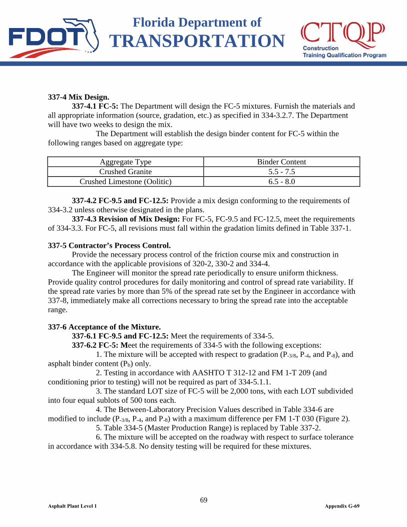
Florida Department of TRANSPORTATION
69
337-4 Mix Design. 337-4.1 FC-5: The Department will design the FC-5 mixtures. Furnish the materials and all appropriate information (source, gradation, etc.) as specified in 334-3.2.7. The Department will have two weeks to design the mix. The Department will establish the design binder content for FC-5 within the following ranges based on aggregate type:
Aggregate Type Binder Content Crushed Granite 5.5 - 7.5
Crushed Limestone (Oolitic) 6.5 - 8.0 337-4.2 FC-9.5 and FC-12.5: Provide a mix design conforming to the requirements of 334-3.2 unless otherwise designated in the plans. 337-4.3 Revision of Mix Design: For FC-5, FC-9.5 and FC-12.5, meet the requirements of 334-3.3. For FC-5, all revisions must fall within the gradation limits defined in Table 337-1.
337-5 Contractor’s Process Control. Provide the necessary process control of the friction course mix and construction in accordance with the applicable provisions of 320-2, 330-2 and 334-4. The Engineer will monitor the spread rate periodically to ensure uniform thickness. Provide quality control procedures for daily monitoring and control of spread rate variability. If the spread rate varies by more than 5% of the spread rate set by the Engineer in accordance with 337-8, immediately make all corrections necessary to bring the spread rate into the acceptable range.
337-6 Acceptance of the Mixture. 337-6.1 FC-9.5 and FC-12.5: Meet the requirements of 334-5. 337-6.2 FC-5: Meet the requirements of 334-5 with the following exceptions: 1. The mixture will be accepted with respect to gradation (P-3/8, P-4, and P-8), and asphalt binder content (Pb) only. 2. Testing in accordance with AASHTO T 312-12 and FM 1-T 209 (and conditioning prior to testing) will not be required as part of 334-5.1.1. 3. The standard LOT size of FC-5 will be 2,000 tons, with each LOT subdivided into four equal sublots of 500 tons each. 4. The Between-Laboratory Precision Values described in Table 334-6 are modified to include (P-3/8, P-4, and P-8) with a maximum difference per FM 1-T 030 (Figure 2). 5. Table 334-5 (Master Production Range) is replaced by Table 337-2. 6. The mixture will be accepted on the roadway with respect to surface tolerance in accordance with 334-5.8. No density testing will be required for these mixtures.
Asphalt Plant Level 1 Appendix G-69
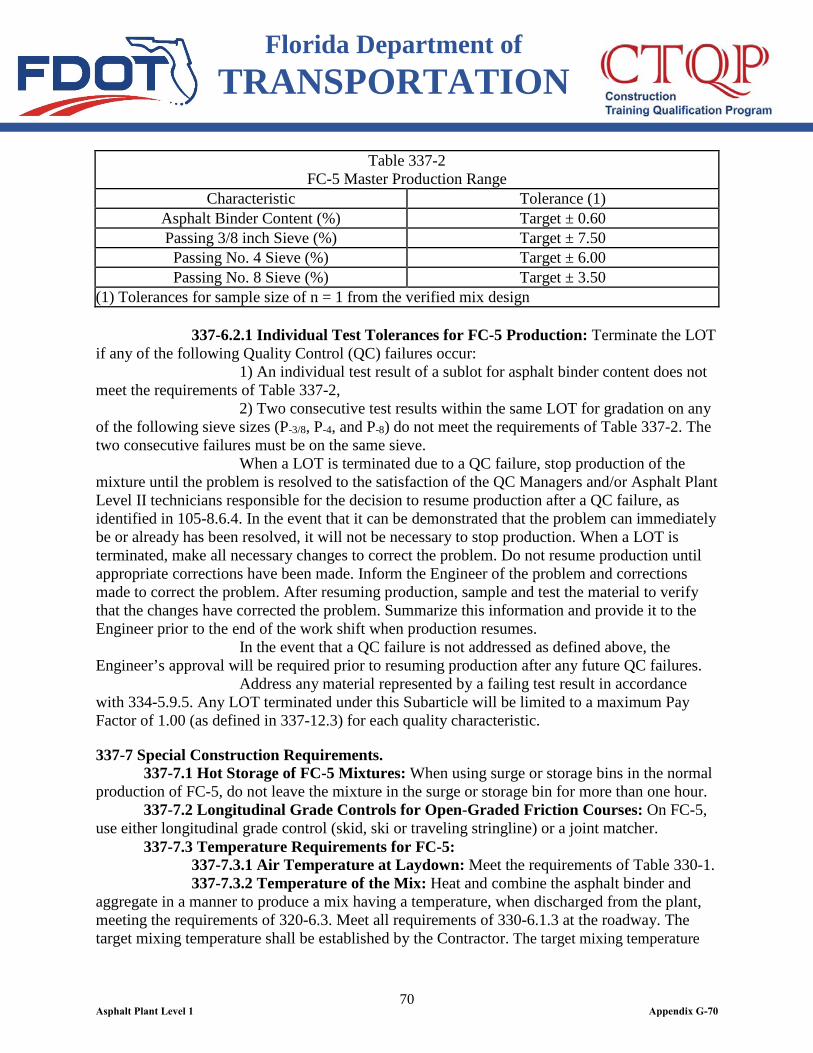
Florida Department of TRANSPORTATION
70
Table 337-2 FC-5 Master Production Range
Characteristic Tolerance (1) Asphalt Binder Content (%) Target ± 0.60 Passing 3/8 inch Sieve (%) Target ± 7.50
Passing No. 4 Sieve (%) Target ± 6.00 Passing No. 8 Sieve (%) Target ± 3.50
(1) Tolerances for sample size of n = 1 from the verified mix design 337-6.2.1 Individual Test Tolerances for FC-5 Production: Terminate the LOT if any of the following Quality Control (QC) failures occur: 1) An individual test result of a sublot for asphalt binder content does not meet the requirements of Table 337-2, 2) Two consecutive test results within the same LOT for gradation on any of the following sieve sizes (P-3/8, P-4, and P-8) do not meet the requirements of Table 337-2. The two consecutive failures must be on the same sieve. When a LOT is terminated due to a QC failure, stop production of the mixture until the problem is resolved to the satisfaction of the QC Managers and/or Asphalt Plant Level II technicians responsible for the decision to resume production after a QC failure, as identified in 105-8.6.4. In the event that it can be demonstrated that the problem can immediately be or already has been resolved, it will not be necessary to stop production. When a LOT is terminated, make all necessary changes to correct the problem. Do not resume production until appropriate corrections have been made. Inform the Engineer of the problem and corrections made to correct the problem. After resuming production, sample and test the material to verify that the changes have corrected the problem. Summarize this information and provide it to the Engineer prior to the end of the work shift when production resumes. In the event that a QC failure is not addressed as defined above, the Engineer’s approval will be required prior to resuming production after any future QC failures. Address any material represented by a failing test result in accordance with 334-5.9.5. Any LOT terminated under this Subarticle will be limited to a maximum Pay Factor of 1.00 (as defined in 337-12.3) for each quality characteristic.
337-7 Special Construction Requirements. 337-7.1 Hot Storage of FC-5 Mixtures: When using surge or storage bins in the normal production of FC-5, do not leave the mixture in the surge or storage bin for more than one hour. 337-7.2 Longitudinal Grade Controls for Open-Graded Friction Courses: On FC-5, use either longitudinal grade control (skid, ski or traveling stringline) or a joint matcher. 337-7.3 Temperature Requirements for FC-5: 337-7.3.1 Air Temperature at Laydown: Meet the requirements of Table 330-1. 337-7.3.2 Temperature of the Mix: Heat and combine the asphalt binder and aggregate in a manner to produce a mix having a temperature, when discharged from the plant, meeting the requirements of 320-6.3. Meet all requirements of 330-6.1.3 at the roadway. The target mixing temperature shall be established by the Contractor. The target mixing temperature
Asphalt Plant Level 1 Appendix G-70
Florida Department of TRANSPORTATION
71
may be reduced when using warm mix technology. 337-7.4 Compaction of FC-5: Provide two, static steel-wheeled rollers, with an effective compactive weight in the range of 135 to 200 pounds per linear inch (PLI), determined as follows:
(inches) Drums of Width Total(pounds)Roller of Weight TotalPLI =
(Any variation of this equipment requirement must be approved by the Engineer.) Establish an appropriate rolling pattern for the pavement in order to effectively seat the mixture without crushing the aggregate. In the event that the roller begins to crush the aggregate, reduce the number of coverages or the PLI of the rollers. If the rollers continue to crush the aggregate, use a tandem steel-wheel roller weighing not more than 135 PLI of drum width. 337-7.5 Temperature Requirements for FC-9.5 and FC-12.5: 337-7.5.1 Air Temperature at Laydown: Meet the requirements of Table 330-1. 337-7.5.2 Temperature of the Mix: Heat and combine the asphalt binder and aggregate in a manner to produce a mix having a temperature, when discharged from the plant, meeting the requirements of 320-6.3. Meet all requirements of 330-6.1.3 at the roadway. 337-7.6 Prevention of Adhesion: To minimize adhesion to the drum during the rolling operations, the Contractor may add a small amount of liquid detergent to the water in the roller. At intersections and in other areas where the pavement may be subjected to cross-traffic before it has cooled, spray the approaches with water to wet the tires of the approaching vehicles before they cross the pavement. 337-7.7 Transportation Requirements of Friction Course Mixtures: Cover all loads of friction course mixtures with a tarpaulin, or waterproof cover, meeting requirements of 320-7.
337-8 Thickness of Friction Courses. 337-8.1 FC-12.5 and FC-9.5: The thickness of the friction course layer will be the plan thickness as shown in the Contract Documents. For construction purposes, the plan thickness will be converted to spread rate as defined in 334-1.4. Plan quantities are based on a Gmm of 2.540, corresponding to a spread rate of 110 lbs/yd2-in. Pay quantities will be based on the actual maximum specific gravity of the mix being used. 337-8.2 FC-5: The total thickness of the FC-5 layer will be the plan thickness as shown in the Contract Documents. For construction purposes, the plan thickness will be converted to spread rate based on the combined aggregate bulk specific gravity of the asphalt mix being used as shown in the following equation: Spread rate (lbs/yd2) = t x Gsb x 40.5 Where: t = Thickness (in.) (Plan thickness) Gsb = Combined aggregate bulk specific gravity from the verified mix design
Asphalt Plant Level 1 Appendix G-71
Florida Department of TRANSPORTATION
72
The weight of the mixture shall be determined as provided in 320-3.2. Plan quantities are based on a Gsb of 2.635, corresponding to a spread rate of 80 pounds per square yard for a 3/4 inch layer. Pay quantities will be based on the actual combined aggregate bulk specific gravity (Gsb) of the mix being used.
337-9 Special Equipment Requirements for FC-5. 337-9.1 Fiber Supply System: Use a separate feed system to accurately proportion the required quantity of mineral fibers into the mixture in such a manner that uniform distribution is obtained. Interlock the proportioning device with the aggregate feed or weigh system to maintain the correct proportions for all rates of production and batch sizes. Control the proportion of fibers to within plus or minus 10% of the amount of fibers required. Provide flow indicators or sensing devices for the fiber system, interlocked with plant controls so that the mixture production will be interrupted if introduction of the fiber fails. When a batch plant is used, add the fiber to the aggregate in the weigh hopper or as approved and directed by the Engineer. Increase the batch dry mixing time by 8 to 12 seconds, or as directed by the Engineer, from the time the aggregate is completely emptied into the pugmill. Ensure that the fibers are uniformly distributed prior to the addition of asphalt rubber into the pugmill. When a drum-mix plant is used, add and uniformly disperse the fiber with the aggregate prior to the addition of the asphalt rubber. Add the fiber in such a manner that it will not become entrained in the exhaust system of the drier or plant. 337-9.2 Hydrated Lime Supply System: For FC-5 mixes containing granite, use a separate feed system to accurately proportion the required quantity of hydrated lime into the mixture in such a manner that uniform coating of the aggregate is obtained prior to the addition of the asphalt rubber. Add the hydrated lime in such a manner that it will not become entrained in the exhaust system of the drier or plant. Interlock the proportioning device with the aggregate feed or weigh system to maintain the correct proportions for all rates of production and batch sizes and to ensure that all mixture produced is properly treated with hydrated lime. Control the proportion of hydrated lime to within plus or minus 10% of the amount of hydrated lime required. Provide and interlock flow indicators or sensing devices for the hydrated lime system with plant controls so that the mixture production will be interrupted if introduction of the hydrated lime fails. The addition of the hydrated lime to the aggregate may be accomplished by Method A or B as follows: 337-9.2.1 Method A - Dry Form: Add hydrated lime in a dry form to the mixture according to the type of asphalt plant being used. When a batch plant is used, add the hydrated lime to the aggregate in the weigh hopper or as approved and directed by the Engineer. Increase the batch dry mixing time by eight to twelve seconds, or as directed by the Engineer, from the time the aggregate is completely emptied into the pugmill. Uniformly distribute the hydrated lime prior to the addition of asphalt rubber into the pugmill. When a drum-mix plant is used, add and uniformly disperse the hydrated lime to the aggregate prior to the addition of the asphalt rubber. Add the hydrated lime in such a manner that it will not become entrained in the exhaust system of the drier or plant. 337-9.2.2 Method B - Hydrated Lime/Water Slurry: Add the required quantity
Asphalt Plant Level 1 Appendix G-72
Florida Department of TRANSPORTATION
73
of hydrated lime (based on dry weight) in a hydrated lime/water slurry form to the aggregate. Provide a solution consisting of hydrated lime and water in concentrations as directed by the Engineer. Use a plant equipped to blend and maintain the hydrated lime in suspension and to mix it with the aggregates uniformly in the proportions specified. 337-9.3 Hydrated Lime Pretreatment: For FC-5 mixes containing granite, as an alternative to 337-9.2, pretreat the aggregate with hydrated lime prior to incorporating the aggregate into the mixture. Use a feed system to accurately proportion the aggregate and required quantity of hydrated lime, and mix them in such a manner that uniform coating of the aggregate is obtained. Control the proportion of hydrated lime to within plus or minus 10% of the amount required. Aggregate pretreated with hydrated lime in this manner shall be incorporated into the asphalt mixture within 45 days of pretreatment. 337-9.3.1 Hydrated Lime Pretreatment Methods: Pretreat the aggregate using one of the following two methods: Pretreatment Method A - Dry Form: Add the required quantity of hydrated lime in a dry form to the aggregate. Assure that the aggregate at the time of pretreatment contains a minimum of 3% moisture over saturated surface dry (SSD) conditions. Utilize equipment to accurately proportion the aggregate and hydrated lime and mix them in such a manner as to provide a uniform coating. Pretreatment Method B - Hydrated Lime/Water Slurry: Add the required quantity of hydrated lime (based on dry weight) in a hydrated lime/water slurry form to the aggregate. Provide a solution consisting of hydrated lime and water in a concentration to provide effective treatment. Use equipment to blend and maintain the hydrated lime in suspension, to accurately proportion the aggregate and hydrated lime/water slurry, and to mix them to provide a uniform coating. 337-9.3.2 Blending QC Records: Maintain adequate QC records for the Engineer’s review for all pretreatment activities. Include as a minimum the following information (for each batch or day’s run of pretreatment): pretreatment date, aggregate certification information, certified test results for the hydrated lime, aggregate moisture content prior to blending, as-blended quantities of aggregate and hydrated lime, project number, customer name, and shipping date. 337-9.3.3 Certification: In addition to the aggregate certification, provide a certification with each load of material delivered to the hot mix asphalt plant, that the material has been pretreated in conformance with these specifications. Include also the date the material was pretreated.
337-10 Failing Material. Meet the requirements of 334-5.9. For FC-5, use the Master Production Range defined in Table 337-2 in lieu of Table 334-5.
337-11 Method of Measurement. For the work specified under this Section (including the pertinent provisions of Sections 320 and 330), the quantity to be paid for will be the weight of the mixture, in tons. The pay quantity will be based on the project average spread rate, limited to a maximum of 105% of the spread rate determined in accordance with 337-8 or as set by the Engineer. The project
Asphalt Plant Level 1 Appendix G-73
Florida Department of TRANSPORTATION
74
average spread rate is calculated by totaling the arithmetic mean of the average daily spread rate values for each layer. The bid price for the asphalt mix will include the cost of the asphalt binder (asphalt rubber (or polymer), asphalt cement, ground tire rubber, anti-stripping agent, blending and handling) and the tack coat application as directed in 300-8, as well as fiber stabilizing additive and hydrated lime (if required). There will be no separate payment or unit price adjustment for the asphalt binder material in the asphalt mix. The weight will be determined as provided in 320-3.2 (including the provisions for the automatic recordation system). Prepare a Certification of Quantities, using the Department’s current approved form, for the certified asphalt concrete friction course pay item. Submit this certification to the Engineer no later than Twelve O’clock noon Monday after the estimate cut-off or as directed by the Engineer, based on the quantity of asphalt produced and accepted on the roadway per Contract. The certification must include the Contract Number, FPID Number, Certification Number, Certification Date, period represented by Certification and the tons produced for each asphalt pay item.
337-12 Basis of Payment. 337-12.1 General: Price and payment will be full compensation for all the work specified under this Section (including the applicable requirements of Sections 320 and 330). Based upon the quality of the material, a pay adjustment will be applied to the bid price of the material as determined on a LOT by LOT basis. The pay adjustment will be assessed by calculating a Pay Factor for individual quality characteristics. The pay adjustment will be computed by multiplying a Composite Pay Factor for the LOT by the bid price per ton. Perform all calculations with the Department’s Asphalt Plant - Pay Factor Worksheets. 337-12.2 FC-9.5 and FC-12.5: Meet the requirements of 334-8.
Asphalt Plant Level 1 Appendix G-74
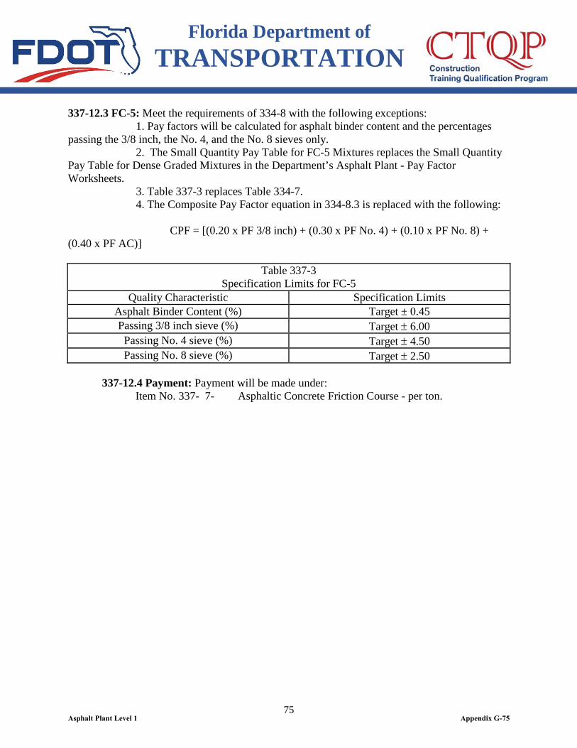
Florida Department of TRANSPORTATION
75
337-12.3 FC-5: Meet the requirements of 334-8 with the following exceptions: 1. Pay factors will be calculated for asphalt binder content and the percentages passing the 3/8 inch, the No. 4, and the No. 8 sieves only. 2. The Small Quantity Pay Table for FC-5 Mixtures replaces the Small Quantity Pay Table for Dense Graded Mixtures in the Department’s Asphalt Plant - Pay Factor Worksheets. 3. Table 337-3 replaces Table 334-7. 4. The Composite Pay Factor equation in 334-8.3 is replaced with the following:
CPF = [(0.20 x PF 3/8 inch) + (0.30 x PF No. 4) + (0.10 x PF No. 8) + (0.40 x PF AC)]
Table 337-3 Specification Limits for FC-5
Quality Characteristic Specification Limits Asphalt Binder Content (%) Target ± 0.45 Passing 3/8 inch sieve (%) Target ± 6.00
Passing No. 4 sieve (%) Target ± 4.50 Passing No. 8 sieve (%) Target ± 2.50
337-12.4 Payment: Payment will be made under:
Item No. 337- 7- Asphaltic Concrete Friction Course - per ton.
Asphalt Plant Level 1 Appendix G-75
Florida Department of TRANSPORTATION
76
SECTION 338 VALUE ADDED ASPHALT PAVEMENT
338-1 Description. Construct Value Added Asphalt Pavement consisting of Asphalt Concrete Structural Course and Asphalt Concrete Friction Course, subject to a three year warranty period after final acceptance of the Contract in accordance with 5-11. For purposes of this Specification, the Responsible Party, as designated herein, is responsible for performance of the Value Added Asphalt Pavement including continued responsibility for performing all remedial work associated with pavement distresses exceeding threshold values determined in accordance with this Section, and as to which notice was provided to the Responsible Party. The work specified in this Section will not be paid for directly, but will be considered as incidental to other Contract items.
338-2 Materials and Construction Requirements. Meet the following requirements:
Hot Bituminous Mixtures - Plant, Methods and Equipment ...........................................................Section 320 Hot Bituminous Mixtures - General Construction Requirements ......................................................Section 330 Superpave Asphalt Concrete ...............................Section 334
Asphalt Concrete Friction Courses .......................Section 337
338-3 Responsible Party. Prior to any Value Added Asphalt Pavement being placed on the project, the Contractor shall designate a Responsible Party to accept responsibility for maintaining the Value Added Asphalt Pavement, when remedial work is required. When the scope of the asphalt work is only milling and resurfacing, and there is no construction of the embankment, subgrade or base below the pavement included in the Contract, the Responsible Party may be either the Contractor or the Department approved subcontractor performing the Value Added Asphalt Pavement work. When the construction of the embankment, subgrade or base below the pavement is included in the Contract, in addition to the construction of the Asphalt Concrete Structural Course and Asphalt Concrete Friction Course, the Contractor shall be considered as the Responsible Party. When the Responsible Party is a subcontractor, the subcontractor must be pre-qualified with the Department in the category of asphalt, and such designation must be made to the Department by the Contractor. The proposed subcontractor must execute and deliver to the Department a form, provided by the Department, prior to or concurrent with the Contractor’s request to sublet any Value Added Asphalt Pavement work, stipulating that the subcontractor assumes all responsibility as the Responsible Party for the Value Added Asphalt Pavement within the three-year warranty period. Failure to timely designate the Responsible Party will result in the Contractor being the Responsible Party unless otherwise agreed to in writing by the Department.
Asphalt Plant Level 1 Appendix G-76

Florida Department of TRANSPORTATION
77
Upon final acceptance of the Contract in accordance with 5-11, the Contractor’s responsibility for maintenance of all the work or facilities within the project limits of the Contract will terminate in accordance with 5-11; with the sole exception that the obligations set forth in this Section for Value Added Asphalt Pavement will continue thereafter to be the responsibility of the Responsible Party as otherwise provided in this Section.
338-4 Statewide Disputes Review Board. The Statewide Disputes Review Board in effect for this Contract will resolve any and all disputes that may arise involving administration and enforcement of this Specification. The Responsible Party and the Department acknowledge that use of the Statewide Disputes Review Board is required, and the determinations of the Statewide Disputes Review Board for disputes arising out of this Specification will be binding on both the Responsible Party and the Department, with no right of appeal by either party. Meet the requirements of 8-3.
338-5 Pavement Evaluation and Remedial Work. 338-5.1 General: The Department’s Pavement Condition Survey Program, along with observations by the Engineer, will be used as the basis for determining the extent and the magnitude of the pavement distresses occurring on the project. In the event the level of distress exceeds any of the threshold values defined below, remedial work as described in 338-5.5 by the Responsible Party will be required. The Department will monitor the pavement for distresses and may require remedial action at any time. For evaluation purposes, the project will be subdivided into LOTs of 0.1 mile per lane. When the segment is less than 0.1 mile, the segment will be called a partial LOT. For purposes of threshold values and remedial work, partial lots and lots will be treated as lots. The Department may conduct a Pavement Condition Survey of the value added pavement following the final acceptance of the project, and at intermediate times throughout the warranty period with findings provided when considered by the Department to be the obligation of the Responsible Party. The final survey, if determined by the Engineer to be necessary, will be conducted before the end of the warranty period with results provided to the Responsible Party for those conditions exceeding contract threshold values requiring remedial action that the Department believes to be an obligation of the Responsible Party. The Department will be responsible for all costs associated with the surveys. If the survey findings, intermediate or final, are to be disputed by the Responsible Party, written notification must be provided to the Engineer within 30 calendar days of the date of receipt of the information from the Department. During the warranty period, the Responsible Party may monitor the project using nondestructive methods and may participate with the Department in the Pavement Condition Surveys upon request. The Responsible Party shall not conduct any coring, milling or other destructive methods without prior approval by the Engineer. 338-5.2 Category 1 Pavement: For purposes of this Specification, “Category 1 Pavement” is defined as mainline roadways, access roads and frontage roads with a design speed of 55 mph and greater.
Asphalt Plant Level 1 Appendix G-77

Florida Department of TRANSPORTATION
78
Threshold values and associated remedial work for Category 1 Value Added Asphalt Pavement are specified in Table 338-1.
Asphalt Plant Level 1 Appendix G-78
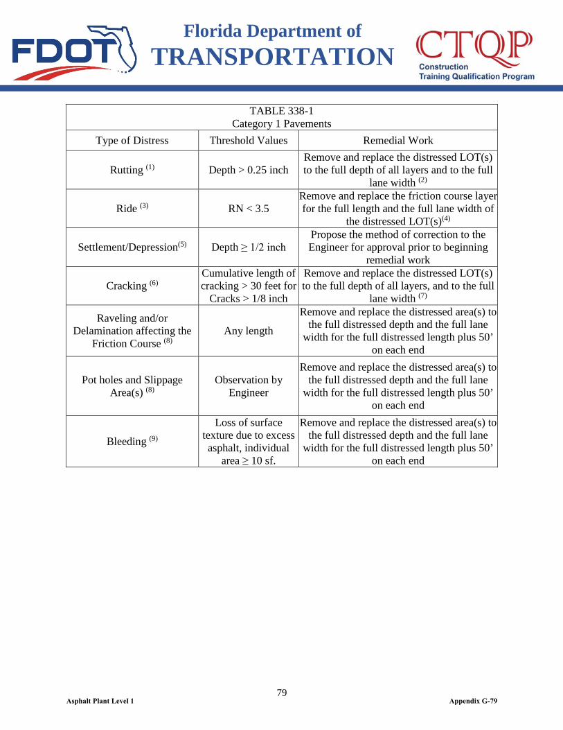
Florida Department of TRANSPORTATION
79
TABLE 338-1 Category 1 Pavements
Type of Distress Threshold Values Remedial Work
Rutting (1) Depth > 0.25 inch Remove and replace the distressed LOT(s) to the full depth of all layers and to the full
lane width (2)
Ride (3) RN < 3.5 Remove and replace the friction course layer for the full length and the full lane width of
the distressed LOT(s)(4)
Settlement/Depression(5) Depth ≥ 1/2 inch Propose the method of correction to the Engineer for approval prior to beginning
remedial work
Cracking (6) Cumulative length of cracking > 30 feet for
Cracks > 1/8 inch
Remove and replace the distressed LOT(s) to the full depth of all layers, and to the full
lane width (7)
Raveling and/or Delamination affecting the
Friction Course (8) Any length
Remove and replace the distressed area(s) to the full distressed depth and the full lane
width for the full distressed length plus 50’ on each end
Pot holes and Slippage Area(s) (8)
Observation by Engineer
Remove and replace the distressed area(s) to the full distressed depth and the full lane
width for the full distressed length plus 50’ on each end
Bleeding (9)
Loss of surface texture due to excess asphalt, individual
area ≥ 10 sf.
Remove and replace the distressed area(s) to the full distressed depth and the full lane
width for the full distressed length plus 50’ on each end
Asphalt Plant Level 1 Appendix G-79

Florida Department of TRANSPORTATION
80
(1) Rutting: Rut depth to be determined by Laser Profiler in accordance with the Flexible Pavement Condition Survey Handbook. For any LOT that cannot be surveyed by Laser Profiler, the rut depth will be determined manually in accordance with the Flexible Pavement Condition Survey Handbook, with the exception that the number of readings per LOT will be one every 20 feet. For a partial LOT, a minimum of three measurements not exceeding 20 feet apart will be made. When the average of the measurements obtained manually exceeds 0.30 inch or if any individual measurement exceeds 0.6 inch, remedial work will be required. (2) Remedial Work for Rutting: The Contractor may propose removal and replacement of less than the full depth of all layers by preparation and submittal of a signed and sealed engineering analysis report, demonstrating the actual extent of the distressed area(s). Remedial work must be performed in accordance with Table 338-1 unless approved otherwise by the Engineer. (3) Ride: Ride Number (RN) to be established by Laser Profiler in accordance with FM 5-549. (4)If the deficient ride is due to underlying asphalt layers; base, subgrade, or embankment which were constructed by the Responsible Party, propose the method of correction to the Engineer for approval prior to beginning the remedial work. (5)Settlement/Depression: Depth of the settlement/depression to be determined by a 6 foot manual straightedge. (6) Cracking: Beginning and ending of 1/8 inch cracking will be determined as the average of three measurements taken at one foot intervals. The longitudinal construction joint at the lane line will not be considered as a crack. (7) Remedial Work for Cracking: The Contractor may propose removal and replacement of less than the full depth of all layers by preparation and submittal of a signed and sealed engineering analysis report, demonstrating the actual extent of the distressed area(s). Remedial work must be performed in accordance with Table 338-1 unless approved otherwise by the Engineer. (8) Raveling, Delamination, Pot holes, Slippage: As defined and determined by the Engineer in accordance with the examples displayed at the following URL: http://www.dot.state.fl.us/SpecificationsOffice/Implemented/URLinSpecs/Pavement.shtm (9) Bleeding: Bleeding to be defined and determined by the Engineer in accordance with the examples displayed at the following URL: http://www.dot.state.fl.us/SpecificationsOffice/Implemented/URLinSpecs/Pavement.shtm 338-5.3 Category 2 Pavement: For purposes of this Specification, ”Category 2 Pavement” is defined as mainline roadways, access roads and frontage roads with a design speed less than 55 mph; approach transition and merge areas at toll booths; ramps; acceleration and deceleration lanes (including tapers); turn lanes; parking areas; rest areas; weigh stations; and agricultural inspection stations. Threshold values and associated remedial work for Category 2 Value Added Asphalt Pavement are specified in Table 338-2.
TABLE 338-2 Category 2 Pavements
Type of Distress Threshold Values Remedial Work
Rutting(1)
Measured by Laser Profiler: See Table 338-1
See Table 338-1
Manual Measurement: Avg. Depth > 0.4 inch
Remove and replace 1.5 inch(1a) the full lane width for the area plus 50 feet
Cracking Cumulative length of cracking
> 300 feet for Cracks > 1/8 inch
See Table 338-1
Surface Deterioration (2) See Table 338-1 See Table 338-1
Settlement/Depression(3) Depth ≥ 1/2 inch See Table 338-1 (1) Rutting: Rut depth to be determined by Laser Profiler in accordance with the Flexible Pavement Condition Survey Handbook. For any LOT that cannot be surveyed by the Laser Profiler, the rut depth will be determined manually in accordance with the Flexible Pavement Condition Survey Handbook, with the exception that the number of readings per LOT will be one every 20 feet. For partial LOT, minimum of three measurements not exceeding 20 feet apart will be checked. When the average of the
Asphalt Plant Level 1 Appendix G-80
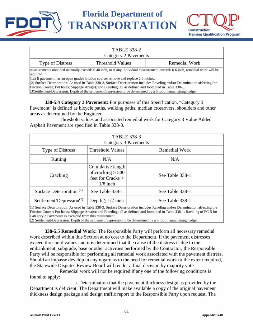
Florida Department of TRANSPORTATION
81
TABLE 338-2 Category 2 Pavements
Type of Distress Threshold Values Remedial Work measurements obtained manually exceeds 0.40 inch, or if any individual measurement exceeds 0.6 inch, remedial work will be required. (1a) If pavement has an open graded friction course, remove and replace 2.0 inches. (2) Surface Deterioration: As used in Table 338-2, Surface Deterioration includes Raveling and/or Delamination affecting the Friction Course; Pot holes; Slippage Area(s); and Bleeding; all as defined and footnoted in Table 338-1.
(3)Settlement/Depression: Depth of the settlement/depression to be determined by a 6 foot manual straightedge. 338-5.4 Category 3 Pavement: For purposes of this Specification, “Category 3 Pavement” is defined as bicycle paths, walking paths, median crossovers, shoulders and other areas as determined by the Engineer. Threshold values and associated remedial work for Category 3 Value Added Asphalt Pavement are specified in Table 338-3.
TABLE 338-3 Category 3 Pavements
Type of Distress Threshold Values Remedial Work
Rutting N/A N/A
Cracking
Cumulative length of cracking > 500 feet for Cracks >
1/8 inch
See Table 338-1
Surface Deterioration (1) See Table 338-1 See Table 338-1
Settlement/Depression(2) Depth ≥ 1/2 inch See Table 338-1 (1) Surface Deterioration: As used in Table 338-3, Surface Deterioration includes Raveling and/or Delamination affecting the Friction Course; Pot holes; Slippage Area(s); and Bleeding; all as defined and footnoted in Table 338-1. Raveling of FC-5 for Category 3 Pavements is excluded from this requirement. (2) Settlement/Depression: Depth of the settlement/depression to be determined by a 6 foot manual straightedge. 338-5.5 Remedial Work: The Responsible Party will perform all necessary remedial work described within this Section at no cost to the Department. If the pavement distresses exceed threshold values and it is determined that the cause of the distress is due to the embankment, subgrade, base or other activities performed by the Contractor, the Responsible Party will be responsible for performing all remedial work associated with the pavement distress. Should an impasse develop in any regard as to the need for remedial work or the extent required, the Statewide Disputes Review Board will render a final decision by majority vote. Remedial work will not be required if any one of the following conditions is found to apply: a. Determination that the pavement thickness design as provided by the Department is deficient. The Department will make available a copy of the original pavement thickness design package and design traffic report to the Responsible Party upon request. The
Asphalt Plant Level 1 Appendix G-81
Florida Department of TRANSPORTATION
82
Responsible Party is responsible for performing all remedial work associated with the pavement distress if the pavement design is provided by the Contractor. b. Determination that the Accumulated ESALs (Number of 18 Kip Equivalent Single Axle Loads in the design lane) has increased by 25% or more than the Accumulated ESALs used by the Department for design purposes for the warranty period for the pavement design life. In calculating ESALs, the Average Annual Daily Traffic (AADT) will be obtained from the Department’s traffic count data and the T24 (Percent Heavy Trucks during a 24 hour period) will be obtained from the Department’s traffic classification survey data. c. Determination that the deficiency was due to the failure of the existing underlying layers that were not part of the Contract work. d. Determination that the deficiency was the responsibility of a third party or its actions, unless the third party was performing work included in the Contract. If a measured distress value indicates remedial action is required per Table 338-1, Table 338-2 and/or Table 338-3, the Responsible Party must begin remedial work within 45 calendar days of notification by the Department or a ruling of the Statewide Disputes Review Board. The Disputes Review Board will determine the allowable duration for the completion of the remedial work, but not to exceed 6 months. In the event remedial action is necessary and forensic information is required to determine the source of the distress, the Department may core and/or trench the pavement. The Responsible Party will not be responsible for damages to the pavement as a result of any forensic activities conducted by the Department. As applicable to distress criteria for rutting, ride and cracking for Category 1 and Category 2 pavements, when two LOTs requiring remedial action are not separated by three or more LOTs not requiring remedial action, the remedial work shall be required for the total length of all such contiguous LOTs, including the intermediate LOTs not requiring remedial action. Additionally, for Category 1 and Category 2 pavements, where such areas of remedial action are required due to raveling, slippage or bleeding are separated by less than 1,000 feet, the remedial work will be required for the entire area contiguous to the distressed areas, including intermediate areas otherwise requiring no remedial action. The Responsible Party has the first option to perform all remedial work that is determined by the Department to be their responsibility. If, in the opinion of the Engineer, the problem poses an immediate danger to the traveling public and the Responsible Party cannot provide temporary mitigation for the defect within 4 hours of written notification and restore the pavement to its original design condition within 72 hours of written notification, the Engineer has the authority to have the remedial work performed by other forces. Temporary mitigation includes the use of traffic control systems such as barricades, drums, or other approved devices to secure the area including lane closures if necessary, and constructing temporary repairs making it safe for the roadway user until the defect can be restored to its original design condition. The Responsible Party is responsible for all incurred costs of the work performed by other forces should the problem (remedial work) be determined to be the responsibility of the Responsible Party. Remedial work performed by other forces does not alter any of the requirements, responsibilities or obligations of the Responsible Party.
Asphalt Plant Level 1 Appendix G-82
Florida Department of TRANSPORTATION
83
The Responsible Party must complete all remedial work to the satisfaction of the Engineer. Any disputes regarding the adequacy of the remedial work will be resolved by the Statewide Disputes Review Board. Approval of remedial work does not relieve the Responsible Party from continuing responsibility under the provisions of this Specification. Notify the Engineer in writing prior to beginning any remedial work. Meet the requirements of the Department’s Standard Specifications for Road and Bridge Construction and implemented modifications thereto when performing any remedial work. Perform all signing and traffic control in accordance with the current edition of the Department’s Design Standards for Design, Construction, Maintenance and Utility Operations on the State Highway System. Provide Maintenance of Traffic during remedial work at no additional cost to the Department. Lane closure restrictions listed in the original Contract will apply to remedial work. Written request(s) to obtain permission for lane closure(s) for either forensic investigation or remedial work must be made to the Engineer 48 hours in advance of any lane closures. Do not perform any lane closures until written permission is given by the Engineer. If remedial work necessitates a corrective action to overlying asphalt layers, pavement markings, signal loops, adjacent lane(s), roadway shoulders, or other affected Contract work, perform these corrective actions using similar products at no additional cost to the Department.
338-6 Responsible Party’s Failure to Perform. Should the Responsible Party fail to timely submit any dispute to the Statewide Disputes Review Board, fail to satisfactorily perform any remedial work, or fail to compensate the Department for any remedial work performed by the Department and determined to be the Responsible Party’s responsibility in accordance with this Specification, the Department will suspend, revoke or deny the Responsible Party’s certificate of qualification under the terms of Section 337.16(d)(2), Florida Statutes, for a minimum of 6 months or until the remedial work has been satisfactorily performed (or full and complete payment for remedial work performed by others made to the Department), whichever is longer. Should the Responsible Party choose to challenge the Department’s notification of intent for suspension, revocation or denial of qualification and the Department’s action is upheld, the Responsible Party will have its qualification suspended for an additional minimum of 6 months. The remedial work is not an obligation of the Contractor’s bond required by Section 337.18, Florida Statutes.
Asphalt Plant Level 1 Appendix G-83
Florida Department of TRANSPORTATION
84
SECTION 339 MISCELLANEOUS ASPHALT PAVEMENT
339-1 Description. Construct asphalt pavement in areas where vehicular traffic does not travel, such as pavement under guardrail, bicycle paths, median pavement, sidewalks, etc. Also, chemically treat the underlying soil to prevent plant growth.
339-2 Materials. For the pavement, use any plant-mixed hot bituminous mixture meeting the requirements of a mix design verified by the Engineer, except do not use open-graded friction course (FC-5). For bicycle paths, use a mixture that produces a finished pavement which will not distort or mar under bicycle or mower wheel loads. In general, the Engineer will accept the mixture on the basis of visual inspection with no further testing required.
339-3 Foundation and Soil Treatment. Shape the soil in areas where pavement is to be constructed, to a surface true to the lines, grades and typical cross-sections shown in the Plans. Compact the soil to a firm state. Immediately before placing the pavement, uniformly apply a pre-emergent herbicide in accordance with the requirements of 7-1.7, to the foundation soil. Ensure that the herbicide carries an approved label for use under paved surfaces, and that herbicide is applied in accordance with directions on the label. Prevent damage to any adjacent vegetation during herbicide application. Replace, at no expense to the Department, any plants damaged as the result of soil treatment outside designated areas.
339-4 Placing Mixture. Uniformly place the hot bituminous mixture by machine or hand methods at the rate of spread or dimensions indicated in the Plans or as otherwise directed by the Engineer. If posts are to be constructed within the pavement area, the Contractor may cut holes for installation through the completed pavement. After completing installation of posts and compaction of the backfill material, patch the area around each post with fresh hot bituminous mixture. If directed by the Engineer, place miscellaneous asphalt pavement prior to placement of the final surface course.
339-5 Compacting Mixture. Uniformly compact the hot bituminous mixture with lightweight rollers or vibratory compactors as directed by the Engineer. The Contractor may use hand tamps for compaction in areas which are inaccessible to other compaction equipment. The Engineer will not require a specific density.
Asphalt Plant Level 1 Appendix G-84
Florida Department of TRANSPORTATION
85
339-6 Surface Requirements. Provide a finished surface that is reasonably smooth, of uniform texture, and shaped so as to drain without ponding of water. Upon completion of the pavement, shape the surface of the adjacent earth to match the pavement edges.
339-7 Method of Measurement. The quantity to be paid for will be the weight, in tons, determined by an electronic weighing system as described in 320-3.2. The pay quantity will be based on the average spread rate of the area shown in the Plans or authorized by the Engineer or dimensions for the project, limited to a maximum of 105% of the plan thickness quantity. For calculation, a weight of 100 lbs/yd2 per inch thickness of asphalt will be used. Prepare a Certification of Quantities, using the Department’s current approved form, for the certified miscellaneous asphalt pavement pay item. Submit this certification to the Engineer no later than Twelve O’clock noon Monday after the estimate cut-off or as directed by the Engineer, based on the quantity of asphalt produced and accepted on the Contract. The certification must include the Contract Number, FPID Number, Certification Number, Certification Date, period represented by Certification and the tons produced for each asphalt pay item.
339-8 Basis of Payment. Price and payment will be full compensation for all work specified in this Section, including shaping and compacting the foundation, soil sterilization treatment, furnishing of the bituminous material used in the mixture, and shaping of adjacent earth surfaces. Payment will be made under:
Item No. 339- 1- Miscellaneous Asphalt Pavement - per ton.
Asphalt Plant Level 1 Appendix G-85
Florida Department of TRANSPORTATION
86
SECTION 341 ASPHALT RUBBER MEMBRANE INTERLAYER
341-1 Description. Construct an asphalt rubber membrane interlayer composed of a separate application of asphalt rubber binder covered with a single application of aggregate.
341-2 Materials. 341-2.1 Asphalt Rubber Binder: Use ARB-20 meeting the requirements of Section 336. 341-2.2 Cover Material: Use Size No. 6 stone, slag, or gravel meeting the requirements of Section 901.
341-3 Equipment. 341-3.1 Power Broom: Provide a power broom for cleaning the existing pavement capable of removing all loose material from the surface. 341-3.2 Spreading Equipment: Provide a self-propelled aggregate spreader that can be adjusted to accurately apply the cover material at the specified rate and that spreads the material uniformly. 341-3.3 Rollers: Provide self-propelled, pneumatic-tired traffic type rollers equipped with at least 7 smooth-tread, low-pressure tires, and capable of carrying a gross load of at least 8 tons. Maintain a minimum tire inflation pressure of 90 psi, or as specified by the manufacturer, such that in no two tires the air pressure varies more than 5 psi. Load the traffic roller as directed by the Engineer. 341-3.4 Mixing Equipment: Use mixing equipment for asphalt rubber binder designed for that purpose and capable of producing and maintaining a homogeneous mixture of rubber and asphalt cement at the specified temperature. 341-3.5 Pressure Distributor: Use a pressure type distributor to apply asphalt rubber binder capable of maintaining a homogeneous mixture of rubber and asphalt cement at the specified temperature and consistently apply the material in a uniform manner.
341-4 Contractor’s Quality Control. Provide the necessary quality control of the asphalt rubber binder, and interlayer construction in accordance with the Contract requirements. Provide in the Quality Control Plan procedures for monitoring and controlling of rate of application. If the rate of application varies by more than 5% from the rate set by the Engineer in accordance with 341-6, immediately make all corrections necessary to bring the spread rate into the acceptable range. The Engineer may take additional measurements at any time. The Engineer will randomly check the Contractor’s measurement to verify the spread rate.
341-5 Preparation of Asphalt Rubber Binder. Meet the requirements of Section 336 Asphalt Rubber Binder, particularly noting testing and action requirements to be met at the project site/asphalt plant. Combine the materials as rapidly as possible for such a time and at such a temperature that the consistency of the binder approaches that of a semi-fluid material. The Engineer will be the sole judge of when the
Asphalt Plant Level 1 Appendix G-86
Florida Department of TRANSPORTATION
87
material has reached application consistency and will determine if an extender oil or diluent is needed for that purpose. After reaching the proper consistency, proceed with application immediately. Never hold the mixture at temperatures over 350ºF for more than six hours after reaching that temperature.
341-6 Construction Procedure. 341-6.1 Preparation of Surface: Prior to application of the asphalt rubber binder, clean the existing pavement as specified in 300-5. 341-6.2 Application of Asphalt Rubber Binder: Apply the asphalt rubber binder only under the following conditions: a. The air temperature is above 50ºF and rising. b. The pavement is absolutely dry. c. The wind conditions are such that cooling of the asphalt rubber binder will not be so rapid as to prevent good bonding of the aggregate. Uniformly apply the asphalt rubber binder, at the rate of 0.6 to 0.8 gal/yd2 as directed by the Engineer. Use an application rate based on the unit weight as shown in Table 336-1. For conversions to standard 60ºF, refer to 300-9.3. Determine the rate of application after each application operation. 341-6.3 Application of Cover Material: Immediately after application of the asphalt rubber binder, uniformly spread the cover material at a rate of 0.26 and 0.33 ft3/yd2. The Engineer will set the exact rate. Determine the application rate at the beginning of each day’s production, and as needed to control the operation, a minimum of twice per day. Maintain an application rate such that the pavement is covered uniformly with aggregate, and is one aggregate layer thick. For the cover material, use aggregate that is reasonably free of any adherent coatings and that does not contain excessive moisture. Immediately after the application of cover material, check the surface to ensure a uniform distribution of cover material and a smooth surface. Do not separate the application of the asphalt rubber binder and the application of the cover material by more than 300 feet, unless approved by the Engineer. 341-6.4 Rolling: In order to ensure maximum embedment of the aggregate, cover the entire width of the mat immediately by traffic rollers. For the first coverage, provide a minimum of three traffic rollers in order to accomplish simultaneous rolling in echelon of the entire width of the spread. After initial rolling, immediately correct all portions of the completed surface that the Engineer deems are defective (not properly covered by aggregates, fat spots, excessive free aggregate, etc.). Following the first coverage, make additional coverages with traffic rollers as directed by the Engineer. 341-6.5 Traffic Control: For the normal sequence of construction operations, place the first course of asphalt concrete overlay over the membrane prior to opening to traffic.
341-7 Unacceptable Asphalt Rubber Membrane Interlayer. If the asphalt rubber membrane interlayer is unacceptable due to incorrect blending, application rate, or not meeting the requirements of this Section, or damaged prior to placement
Asphalt Plant Level 1 Appendix G-87

Florida Department of TRANSPORTATION
88
of the asphalt concrete layer, remove and replace it as directed by the Engineer at no additional cost to the Department. Do not apply excessive amounts of asphalt rubber binder.
341-8 Placement of Asphalt Concrete Overlay. Ensure that the thickness and temperature of the initial layer of asphalt concrete placed on top of the asphalt rubber membrane interlayer are such that the overlay bonds to the interlayer and the underlying layer without voids or excessive binder. Core the asphalt overlay as directed by the Engineer to evaluate the binder and aggregate spread rates, as well as the effectiveness of the asphalt concrete overlay in producing a well-bonded interlayer.
341-9 Method of Measurement. 341-9.1 Asphalt Rubber Membrane Interlayer: The quantity to be paid for will be plan quantity, in square yards, completed and accepted. 341-9.2 Bituminous Material (Asphalt Rubber Binder-Interlayer): The quantity will be the volume, in gallons, determined as provided in 300-8. 341-9.3 Submittal of Certification of Quantities for Bituminous Material: Prepare a Certification of Quantities, using the Department’s current approved form, for the quantity of bituminous material placed and accepted. Submit this certification to the Engineer no later than Twelve O’clock noon Monday after the monthly estimate cutoff date or as directed by the Engineer. The certification must include the Contract Number, FPID Number, State Project Number, Certification Number and period represented by the Certification.
341-10 Basis of Payment. 341-10.1 Asphalt Rubber Membrane Interlayer: Price and payment will be full compensation for all work specified in this Section, including furnishing cover materials, handling, spreading, rolling, bituminous material, and other incidental work necessary to complete this item. 341-10.2 Bituminous Material (Asphalt Rubber Binder-Interlayer): Payment will be included in the price of the asphalt rubber membrane interlayer and will be full compensation for furnishing asphalt cement, ground tire rubber, blending and handling. 341-10.3 Payment Items: Payment will be made under:
Item No. 341- 70- Asphalt Rubber Membrane Interlayer - per square yard.
Asphalt Plant Level 1 Appendix G-88

Florida Department of TRANSPORTATION
89
FLEXIBLE –PAVEMENT MATERIALS SECTION 916
BITUMINOUS MATERIALS
916-1 Superpave PG Asphalt Binder: 916-1.1 Requirements: Superpave Performance Graded (PG) asphalt binders, identified as PG 52-28, PG 58-22, and PG 67-22 shall meet the material requirements of 916-1, and AASHTO M 320-10 Table 1. Polymer Modified Asphalt (PMA) or Asphalt Rubber Binders (ARB), identified as PG 76-22 (PMA), PG 76-22 (ARB), and PG 82-22 (PMA), shall meet the requirements of 916-1 and AASHTO M 332-14. All PG asphalt binders shall meet the following additional requirements: 1. The intermediate test temperature at 10 rad/sec. for the Dynamic Shear Rheometer (DSR) test (AASHTO T 315-12) shall be 26.5ºC for PG grades PG 67 and higher. 2. An additional high temperature grade of PG 67 is added for which the high test temperature at 10 rad/sec for the DSR test (AASHTO T 315-12) shall be 67ºC. 3. All PG asphalt binders having a high temperature designation of PG 67 or lower shall be prepared without modification. 4. All PMA binders having a high temperature designation higher than PG 67 shall be produced with a styrene-butadiene-styrene (SBS) or styrene-butadiene (SB) elastomeric polymer modifier and the resultant binder shall meet all requirements of this Section. 5. Polyphosphoric acid may be used as a modifier not exceeding 0.5% by weight of asphalt binder for PG 76-22 (PMA), PG 76-22 (ARB), and PG 82-22 (PMA) binders. 6. PG 76-22 (ARB) shall meet the additional requirements of 916-1.1.1. 7. Do not substitute a PG binder with a high temperature grade more than 5.9°C higher than the specified PG grade, (for example, if a PG 58-22 is specified, do not supply a PG 64-22 or higher). For all PG binder used in all hot mix asphalt, silicone may be added to the PG binder at the rate of 25 cubic centimeters of silicone mixed to each 5,000 gallons of PG binder. If a disbursing fluid is used in conjunction with the silicone, the resultant mixture containing the full 25 cubic centimeters of silicone shall be added in accordance with the manufacturer’s recommendation. The blending of the silicone with the PG binder shall be done by the supplier prior to the shipment. When the asphalt binder will be used with a foaming warm mix technology, refer to the technology supplier’s guidance on the addition of silicone. Where an anti-strip additive is required, per the requirements of Sections 334 and 337, the amount shall be from 0.25% to 0.75% by weight of asphalt binder. The anti-strip additive shall meet the requirements of 916-5. The anti-strip additive shall be introduced into the PG binder by the supplier during loading. 916-1.1.1 Additional Requirements for PG 76-22 (ARB): The following additional requirements apply only to PG 76-22 (ARB): 1. The asphalt binder shall contain a minimum of 7.0% ground tire rubber (GTR) by weight of asphalt binder. 2. The GTR shall meet the requirements of Section 919.
Asphalt Plant Level 1 Appendix G-89

Florida Department of TRANSPORTATION
90
3. Polymer modification is optional for PG 76-22 (ARB). 4. Use of excess PG 76-22 (ARB): The Contractor may use excess PG 76-22 (ARB) in other asphalt concrete mixes requiring the use of a PG 67-22 binder by blending with straight PG 67-22 binder so that the total amount of ground tire rubber in the binder is less than 2.0%. The Contractor may use excess PG 76-22 (ARB) in asphalt concrete mixtures requiring the use of a PG 52-28 or PG 58-22 by blending with the designated binder in such proportions that the total amount of ground tire rubber in the binder is less than 1.0%. 916-1.2 Reporting: The report, in accordance with 916-5, shall consist of the specification compliance testing and quality control (QC) testing of the following as applicable by these specifications.
Asphalt Plant Level 1 Appendix G-90
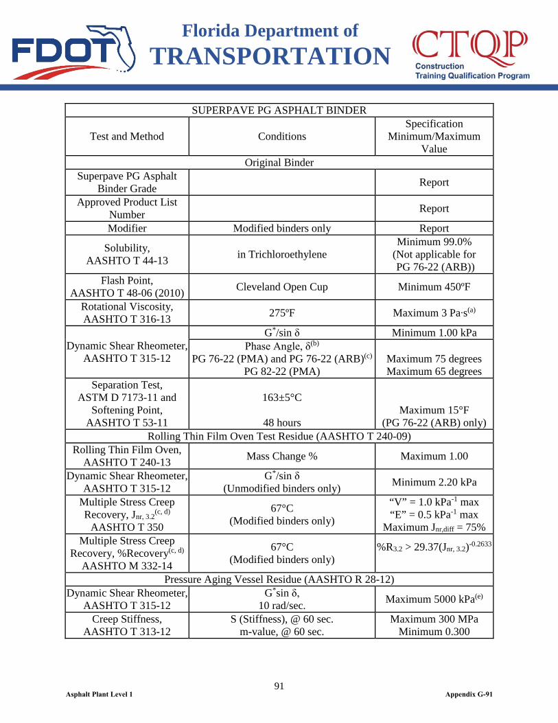
Florida Department of TRANSPORTATION
91
SUPERPAVE PG ASPHALT BINDER
Test and Method Conditions Specification
Minimum/Maximum Value
Original Binder Superpave PG Asphalt
Binder Grade Report
Approved Product List Number Report
Modifier Modified binders only Report
Solubility, AASHTO T 44-13 in Trichloroethylene
Minimum 99.0% (Not applicable for PG 76-22 (ARB))
Flash Point, AASHTO T 48-06 (2010) Cleveland Open Cup Minimum 450ºF
Rotational Viscosity, AASHTO T 316-13 275ºF Maximum 3 Pa∙s(a)
Dynamic Shear Rheometer, AASHTO T 315-12
G*/sin δ Minimum 1.00 kPa Phase Angle, δ(b)
PG 76-22 (PMA) and PG 76-22 (ARB)(c) PG 82-22 (PMA)
Maximum 75 degrees Maximum 65 degrees
Separation Test, ASTM D 7173-11 and
Softening Point, AASHTO T 53-11
163±5°C
48 hours
Maximum 15°F (PG 76-22 (ARB) only)
Rolling Thin Film Oven Test Residue (AASHTO T 240-09) Rolling Thin Film Oven,
AASHTO T 240-13 Mass Change % Maximum 1.00
Dynamic Shear Rheometer, AASHTO T 315-12
G*/sin δ (Unmodified binders only) Minimum 2.20 kPa
Multiple Stress Creep Recovery, Jnr, 3.2
(c, d) AASHTO T 350
67°C (Modified binders only)
“V” = 1.0 kPa-1 max “E” = 0.5 kPa-1 max
Maximum Jnr,diff = 75% Multiple Stress Creep
Recovery, %Recovery(c, d) AASHTO M 332-14
67°C (Modified binders only)
%R3.2 > 29.37(Jnr, 3.2)-0.2633
Pressure Aging Vessel Residue (AASHTO R 28-12) Dynamic Shear Rheometer,
AASHTO T 315-12 G*sin δ,
10 rad/sec. Maximum 5000 kPa(e)
Creep Stiffness, AASHTO T 313-12
S (Stiffness), @ 60 sec. m-value, @ 60 sec.
Maximum 300 MPa Minimum 0.300
Asphalt Plant Level 1 Appendix G-91
Florida Department of TRANSPORTATION
92
(a) Binders with values higher than 3 Pa∙s should be used with caution and only after consulting with the supplier as to any special handling procedures, including pumping capabilities. (b) The original binder phase angle (AASHTO T 315-12) shall be performed at grade temperature. (c) AASHTO T 315-12 and AASHTO T 350-14 will be performed at a 2 mm gap for PG 76-22 (ARB) (d) All binders with a high temperature designation >67 will be tested at 67°C. PG 76-22 (PMA) and PG 76-22 (ARB) shall pass a “V” graded and PG 82-22 (PMA) shall pass an “E” grade per AASHTO M 332-14. (e) For all PG grades of a PG 67 or higher, perform the PAV residue testing at 26.5°C with a maximum of 5000 kPa. 916-1.3 Certification and Verification: The supplier shall furnish certification on the bill of lading for each shipment of PG asphalt binder delivered to a Department project that includes: the quantity, the PG asphalt binder grade (including the Approved Product List (APL) number), PG binder LOT designation, the customer name, the delivery location, a statement that the binder is in conformance with 916-1 and the supplier’s Quality Control Program, and the quantity of silicone and anti-strip agent addition, as applicable, including product designation (APL number as applicable). Additionally, for PG 76-22 (ARB), provide a certification statement on the bill of lading that a minimum of 7.0% GTR by weight of asphalt binder is used in the formulation of the PG 76-22 (ARB). Any special handling or temperature requirements shall be indicated on the certification and are solely the responsibility of the Contractor to follow. The Department may sample and test PG asphalt binder from the supplier’s storage tank, the delivery vehicle, and/or Contractor’s storage tank to verify and determine specification compliance. Where these tests identify material outside specification requirements, the State Materials Engineer may require the supplier to cease shipment of that PG asphalt binder product. Further shipment of that PG asphalt binder product to Department projects may remain suspended until the cause of the problem is evaluated and corrected by the supplier as necessary to the satisfaction of the State Materials Engineer.
916-2 Emulsified Asphalts. 916-2.1 Requirements: Use a prime coat or non-tracking tack coat listed on the APL meeting the requirements of AASHTO M140-08 for anionic emulsions, AASHTO M208-01 (2009) for cationic emulsions, or as provided below. For anionic emulsions, the cement mixing test will be waived when the emulsion is used in non-mix applications, such as prime or tack coats.
Asphalt Plant Level 1 Appendix G-92
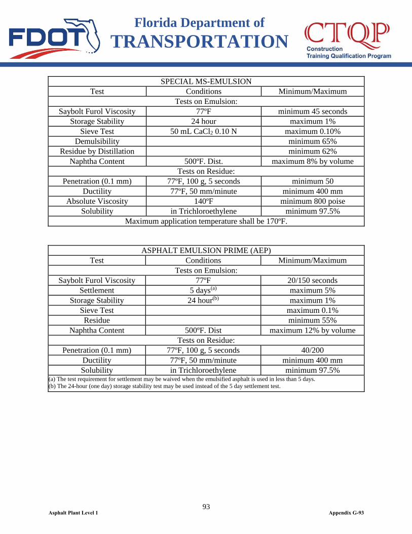
Florida Department of TRANSPORTATION
93
SPECIAL MS-EMULSION Test Conditions Minimum/Maximum
Tests on Emulsion: Saybolt Furol Viscosity 77ºF minimum 45 seconds
Storage Stability 24 hour maximum 1% Sieve Test 50 mL CaCl2 0.10 N maximum 0.10%
Demulsibility minimum 65% Residue by Distillation minimum 62%
Naphtha Content 500ºF. Dist. maximum 8% by volume Tests on Residue:
Penetration (0.1 mm) 77ºF, 100 g, 5 seconds minimum 50 Ductility 77ºF, 50 mm/minute minimum 400 mm
Absolute Viscosity 140ºF minimum 800 poise Solubility in Trichloroethylene minimum 97.5%
Maximum application temperature shall be 170ºF.
ASPHALT EMULSION PRIME (AEP) Test Conditions Minimum/Maximum
Tests on Emulsion: Saybolt Furol Viscosity 77ºF 20/150 seconds
Settlement 5 days(a) maximum 5% Storage Stability 24 hour(b) maximum 1%
Sieve Test maximum 0.1% Residue minimum 55%
Naphtha Content 500ºF. Dist maximum 12% by volume Tests on Residue:
Penetration (0.1 mm) 77ºF, 100 g, 5 seconds 40/200 Ductility 77ºF, 50 mm/minute minimum 400 mm Solubility in Trichloroethylene minimum 97.5%
(a) The test requirement for settlement may be waived when the emulsified asphalt is used in less than 5 days. (b) The 24-hour (one day) storage stability test may be used instead of the 5 day settlement test.
Asphalt Plant Level 1 Appendix G-93
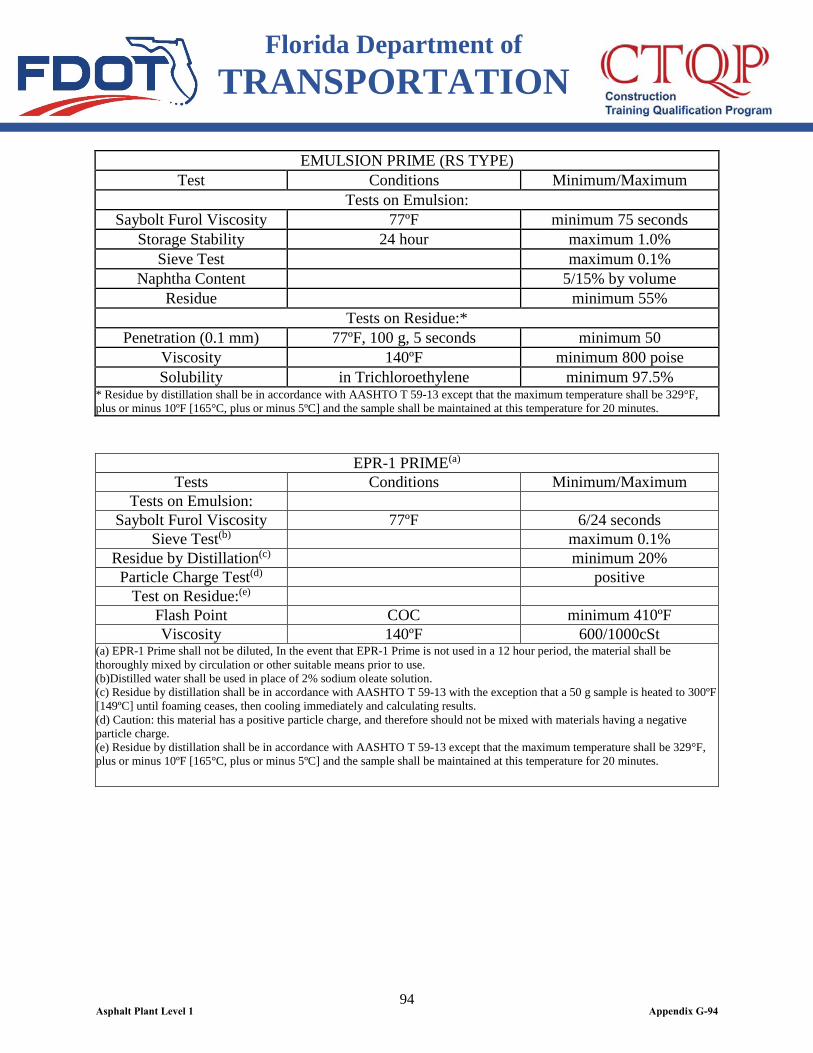
Florida Department of TRANSPORTATION
94
EMULSION PRIME (RS TYPE) Test Conditions Minimum/Maximum
Tests on Emulsion: Saybolt Furol Viscosity 77ºF minimum 75 seconds
Storage Stability 24 hour maximum 1.0% Sieve Test maximum 0.1%
Naphtha Content 5/15% by volume Residue minimum 55%
Tests on Residue:* Penetration (0.1 mm) 77ºF, 100 g, 5 seconds minimum 50
Viscosity 140ºF minimum 800 poise Solubility in Trichloroethylene minimum 97.5%
* Residue by distillation shall be in accordance with AASHTO T 59-13 except that the maximum temperature shall be 329°F, plus or minus 10ºF [165°C, plus or minus 5ºC] and the sample shall be maintained at this temperature for 20 minutes.
EPR-1 PRIME(a) Tests Conditions Minimum/Maximum
Tests on Emulsion: Saybolt Furol Viscosity 77ºF 6/24 seconds
Sieve Test(b) maximum 0.1% Residue by Distillation(c) minimum 20%
Particle Charge Test(d) positive Test on Residue:(e)
Flash Point COC minimum 410ºF Viscosity 140ºF 600/1000cSt
(a) EPR-1 Prime shall not be diluted, In the event that EPR-1 Prime is not used in a 12 hour period, the material shall be thoroughly mixed by circulation or other suitable means prior to use. (b)Distilled water shall be used in place of 2% sodium oleate solution. (c) Residue by distillation shall be in accordance with AASHTO T 59-13 with the exception that a 50 g sample is heated to 300ºF [149ºC] until foaming ceases, then cooling immediately and calculating results. (d) Caution: this material has a positive particle charge, and therefore should not be mixed with materials having a negative particle charge. (e) Residue by distillation shall be in accordance with AASHTO T 59-13 except that the maximum temperature shall be 329°F, plus or minus 10ºF [165°C, plus or minus 5ºC] and the sample shall be maintained at this temperature for 20 minutes.
Asphalt Plant Level 1 Appendix G-94
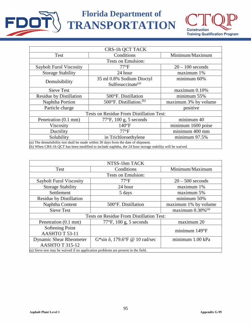
Florida Department of TRANSPORTATION
95
CRS-1h QCT TACK Test Conditions Minimum/Maximum
Tests on Emulsion: Saybolt Furol Viscosity 77°F 20 – 100 seconds
Storage Stability 24 hour maximum 1%
Demulsibility 35 ml 0.8% Sodium Dioctyl Sulfosuccinate(a)
minimum 60%
Sieve Test maximum 0.10% Residue by Distillation 500°F. Distillation minimum 55%
Naphtha Portion 500°F. Distillation.(b) maximum 3% by volume Particle charge positive
Tests on Residue From Distillation Test: Penetration (0.1 mm) 77°F, 100 g, 5 seconds minimum 40
Viscosity 140°F minimum 1600 poise Ductility 77°F minimum 400 mm Solubility in Trichloroethylene minimum 97.5%
(a) The demulsibility test shall be made within 30 days from the date of shipment. (b) When CRS-1h QCT has been modified to include naphtha, the 24 hour storage stability will be waived.
NTSS-1hm TACK Test Conditions Minimum/Maximum
Tests on Emulsion: Saybolt Furol Viscosity 77°F 20 – 500 seconds
Storage Stability 24 hour maximum 1% Settlement 5 days maximum 5%
Residue by Distillation minimum 50% Naphtha Content 500°F. Distillation maximum 1% by volume
Sieve Test maximum 0.30%(a) Tests on Residue From Distillation Test:
Penetration (0.1 mm) 77°F, 100 g, 5 seconds maximum 20 Softening Point
AASHTO T 53-11 minimum 149°F
Dynamic Shear Rheometer AASHTO T 315-12
G*sin δ, 179.6°F @ 10 rad/sec minimum 1.00 kPa
(a) Sieve test may be waived if no application problems are present in the field.
Asphalt Plant Level 1 Appendix G-95
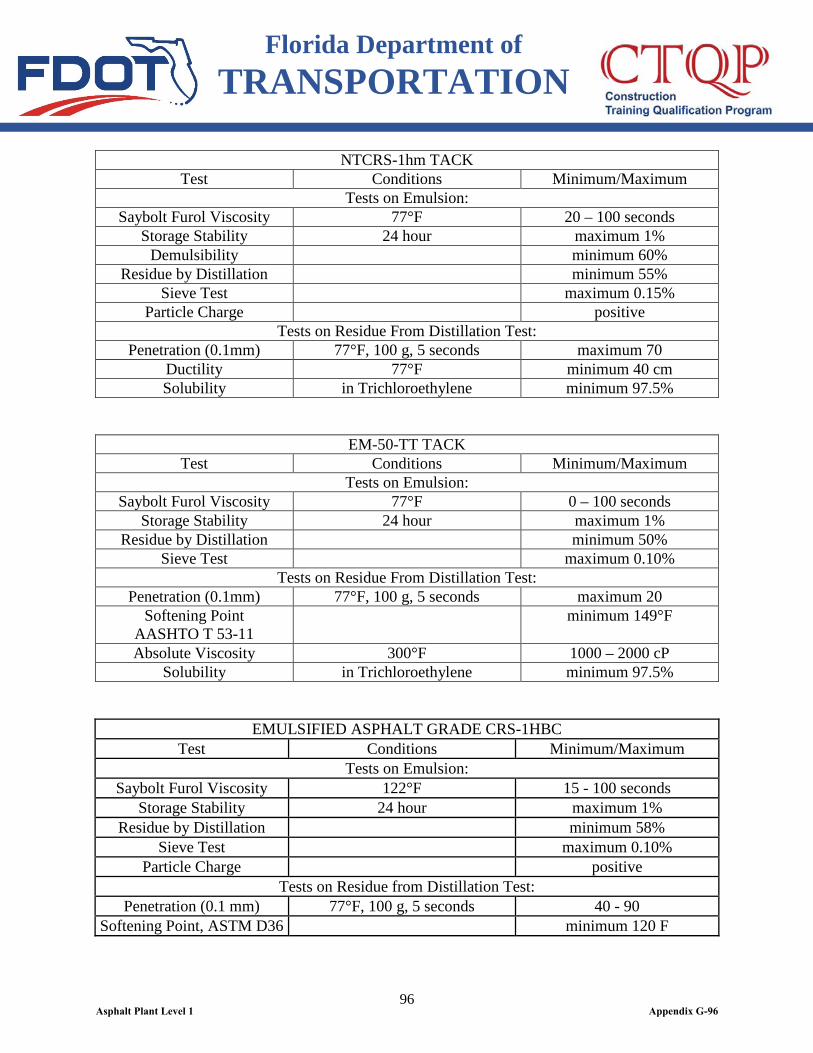
Florida Department of TRANSPORTATION
96
NTCRS-1hm TACK Test Conditions Minimum/Maximum
Tests on Emulsion: Saybolt Furol Viscosity 77°F 20 – 100 seconds
Storage Stability 24 hour maximum 1% Demulsibility minimum 60%
Residue by Distillation minimum 55% Sieve Test maximum 0.15%
Particle Charge positive Tests on Residue From Distillation Test:
Penetration (0.1mm) 77°F, 100 g, 5 seconds maximum 70 Ductility 77°F minimum 40 cm Solubility in Trichloroethylene minimum 97.5%
EM-50-TT TACK Test Conditions Minimum/Maximum
Tests on Emulsion: Saybolt Furol Viscosity 77°F 0 – 100 seconds
Storage Stability 24 hour maximum 1% Residue by Distillation minimum 50%
Sieve Test maximum 0.10% Tests on Residue From Distillation Test:
Penetration (0.1mm) 77°F, 100 g, 5 seconds maximum 20 Softening Point
AASHTO T 53-11 minimum 149°F
Absolute Viscosity 300°F 1000 – 2000 cP Solubility in Trichloroethylene minimum 97.5%
EMULSIFIED ASPHALT GRADE CRS-1HBC Test Conditions Minimum/Maximum
Tests on Emulsion: Saybolt Furol Viscosity 122°F 15 - 100 seconds
Storage Stability 24 hour maximum 1% Residue by Distillation minimum 58%
Sieve Test maximum 0.10% Particle Charge positive
Tests on Residue from Distillation Test: Penetration (0.1 mm) 77°F, 100 g, 5 seconds 40 - 90
Softening Point, ASTM D36 minimum 120 F
Asphalt Plant Level 1 Appendix G-96
Florida Department of TRANSPORTATION
97
916-2.2 Certification, and Verification: The supplier shall furnish certification on the bill of lading for each shipment of emulsified asphalt delivered to a Department project that includes: the producer’s name and location, the quantity, the emulsified asphalt type (including APL number and tank number), emulsified asphalt LOT or Batch designation, the customer name, and a statement that the emulsion is in conformance with the material requirements in 916-2 and the supplier’s QC Plan. Any special handling or temperature requirements shall be indicated on the certification and are the sole responsibility of the Contractor. The Department may sample and test emulsified asphalt from the supplier’s storage tank and/or delivery vehicle to verify and determine specification compliance. Where these tests identify material outside specification requirements, the State Materials Engineer may require the supplier to cease shipment of that emulsified asphalt product. Further shipment of that emulsified asphalt product to Department projects may remain suspended until the cause of the problem is evaluated and corrected by the supplier as necessary to the satisfaction of the State Materials Engineer.
916-3 Liquid Anti-strip Agents. 916-3.1 Requirements: Liquid anti-strip agents shall be tested in accordance with FM 5-508. Tensile strength ratios will be calculated for the following two conditions and expressed as percentages: 1) conditioned mixture without anti-strip to unconditioned mixture without anti-strip and 2) conditioned mixture with anti-strip to unconditioned mixture without anti-strip. A 20% gain in tensile strength ratio for condition 2 as compared to condition 1 shall be required. 916-3.2 Mix Design Verification: Inclusion of a liquid anti-strip agent on the APL does not guarantee that the anti-strip will be approved for use in an asphalt mixture. Specifications may require subsequent moisture susceptibility testing per FM 1-T 283 for the particular mix design. Results from this testing may indicate the need for a larger dosage rate of anti-strip agent (up to 0.75% maximum) or a different anti-strip agent to meet the specification requirements.
916-4 Approved Product List (APL). 916-4.1 General: Any product supplied under this specification shall be one of the products included on the APL. Manufacturers seeking evaluation of a product for inclusion on the APL shall submit an application in accordance with Section 6 and send a sample of the material to the State Materials Office (SMO) to be tested for compliance with the requirements of this specification. Also include split sample testing results from the supplier’s lab or an independent lab for comparison to the SMO’s test results. Any marked variation from these original test values or evidence of inadequate QC or field performance of a material will be considered sufficient evidence that the properties of the material have changed, and the material will be removed from the APL. Suppliers shall not ship any product until notified that the product is on the APL and the QC Plan meets the requirements of 916-5 and has been approved by the Department. 916-4-2 Superpave PG Asphalt Binders: For each binder grade, submit to the SMO one quart of a representative sample. In addition, for modified binders, indicate the original PG binder grade, the modifier product designation, and modifier type on the product evaluation application and in the QC Plan. Additionally, for PG 76-22 (ARB), provide a certification
Asphalt Plant Level 1 Appendix G-97

Florida Department of TRANSPORTATION
98
statement on the product evaluation application and in the QC Plan that a minimum of 7.0% GTR is used in the formulation of the PG 76-22 (ARB). 916-4.3 Emulsified Asphalt: For each emulsified asphalt product, submit to the SMO one gallon of a representative sample.
916-5 Quality Control (QC) Program. 916-5.1 General: The supplier of the PG asphalt binder or emulsified asphalt shall at a minimum have a Quality Control Program meeting the requirements of this Section, AASHTO R 26-01 (2009), and AASHTO PP 71-11. A QC Plan) shall be submitted in an electronic format to the SMO for approval. The requirements of the QC Plan shall apply to the supply location of the PG asphalt binder or emulsified asphalt for use on Department projects only. Any special handling requirements such as rack blending of a PG asphalt binder and the manufacture of polymer and or rubber modified asphalt binder shall be described in the QC Plan. 916-5.2 Identification of Personnel and Supply Locations: The supplier’s primary and secondary representatives responsible for QC shall be identified by name, title, address, telephone, fax and e-mail address. At least one of the representatives shall be located at the supply location. The supply locations shall be identified by name, address and telephone. 916-5.3 Specification Compliance and QC Testing: Specification compliance testing shall consist of complete testing of each PG asphalt binder or emulsified asphalt shipped in accordance with the material requirements in 916-1 and 916-2 of these Specifications. Specification compliance testing shall be conducted by a testing laboratory that participates at least annually in the AASHTO Materials Reference Laboratory (AMRL) Proficiency Sample Program for PG asphalt binder or emulsified asphalts, as applicable. Results of specification compliance testing shall be available to the supplier within five working days of sampling. The primary testing lab and any other labs to be used for specification compliance testing shall be identified in the supplier’s QC Plan. The results from each AMRL Proficiency Sample for each testing laboratory shall be forwarded by the supplier for each supply location in electronic format to the SMO within one week of receiving the results. Acceptable performance in the AMRL Proficiency Sample Program shall be a minimum score of 3 for each test. A rating of less than 3 shall require identification of appropriate action on the part of the supplier and be acceptable to the SMO. Results of QC testing shall be available to the supplier within five hours of sampling. A QC test result outside the specification limits will require immediate sampling and testing for specification compliance and appropriate action taken. The QC testing and location where the test will be done shall be identified in the supplier’s QC Plan. In the event that testing equipment goes out of service, the supplier may elect to test at a qualified lab identified in the supplier’s QC Plan. The QC testing results shall be supplied within 48 hours of the sampling. 916-5.3.1 Superpave PG Asphalt Binders: QC testing at a minimum shall consist of testing a representative sample of each PG asphalt binder shipped by the supplier in accordance with AASHTO T 315-12 Test Method for Determining Rheological Properties of Asphalt Binder using a DSR. 916-5.3.2 Emulsified Asphalts: QC testing at a minimum shall consist of testing a representative sample of each emulsified asphalt shipped by the supplier in accordance with AASHTO T 72-10 Standard Method of Test for Saybolt Viscosity, AASTHO T 59-12 Standard
Asphalt Plant Level 1 Appendix G-98
Florida Department of TRANSPORTATION
99
Test Method for Emulsified Asphalt: Oversized Particles in Emulsified Asphalts (Sieve Test) and Residue by Distillation or Evaporation. 916-5.4 Frequency of Sampling and Testing: Sampling of PG asphalt binders and emulsified asphalts shall be done in accordance with AASHTO T 40-02 (2006). Initial specification compliance testing shall be performed and reported for each PG asphalt binder grade and emulsified asphalt type for each new LOT of material which will be further subjected to QC testing in accordance with 916-5.3. A new LOT will occur when the material in a tank changes or the specification compliance tests are no longer representative of the material in the tank. Any PG asphalt binder or emulsified asphalt shipped to a Department project during any one calendar month shall be tested at least once during that month for specification compliance in accordance with 916-5.3. Split samples of any PG asphalt binder or emulsified asphalt will be provided when requested by a representative of the Department. When split samples are requested by the Department, the results from both parties will be made available within 10 working days. 916-5.4.1 Additional PG Asphalt Binder Testing is as follows: (1) Samples shall be obtained by the supplier and tested for QC testing in accordance with 916-5.3. A single, 1-quart representative sample of each PG asphalt binder shall be obtained and tested by the supplier each calendar week; for each rack blended PG asphalt binder, additional representative samples shall be obtained daily. (2) When split samples are requested, three representative 1-quart samples will be obtained by the supplier under the direction of the Department. One sample will be submitted to the SMO, one will be tested by the supplier for specification compliance and one will be tested by the supplier for QC. (3) For each rack blended PG asphalt binder, identify minimum daily Process Control (PC) testing in the QC Plan. (4) Each QC, specification compliance, Department split samples and additional daily rack blended samples shall be adequately identified and retained for not less than eight weeks at the supply location. 916-5.4.2 Additional Emulsified Asphalt Testing is as follows: (1) Samples shall be obtained by the supplier and tested for QC testing in accordance with 916-5.3. A single, 1-gallon representative sample of each emulsified asphalt shall be obtained and tested by the supplier for each LOT. (2) When split samples are requested, three representative 1-gallon samples will be obtained by the supplier under the direction of the Department. One sample will be submitted to the SMO, one will be tested by the supplier for specification compliance and one will be tested by the supplier for QC. (3) Each QC, specification compliance, and Department split samples shall be adequately identified and retained for not less than four weeks at the supply location. 916-5.5 Reporting: A monthly report by the supplier containing specification compliance and QC test results in accordance with this Section and the supplier’s QC Plan shall be submitted by the supplier to the SMO in electronic format, using the form provided by the
Asphalt Plant Level 1 Appendix G-99
Florida Department of TRANSPORTATION
100
Department, within seven calendar days following the end of the month. Test results for split samples shall also be included. PC test results shall not be included. Copies of the submitted monthly reports and supporting test reports shall be available at the supply location for a minimum of three years. 916-5.6 Notification and Evaluation: In the event that a specification compliance test is outside specification requirements or a QC test is outside limits established by the supplier as part of their QC Plan, shipments of that product to Department projects will cease immediately and the Contractor and the SMO will be notified and the product retested for specification compliance (re-sampling as appropriate). Resume shipment of the product when the retest for specification compliance meets all requirements and with the approval of the SMO.
Asphalt Plant Level 1 Appendix G-100