Embed Size (px)
Citation preview

1
Florida Department of Transportation
Traffic Engineering and Operations
Requirements, Resources, and Application
PRESENTER:
R. “Carlo” Adair, P.E.
ATKINS - Central Florida ITS (Orlando)
ITS Engineer
10 Years Experience
5 Years with ATKINS
ITS Design
Signal Design
Technical Writer
Utility/Power/Stakeholder Coordination
Project Management

2
Provide insight into practices associated
with fiber optic cable design including:
specifications, pay-items, Design Standards,
and industry practices.
Standard Specifications for Road and
Bridge Construction
Minimum Specifications for Traffic
Control Signals and Devices (MSTCSD)
FDOT Design Standards
Basis of Estimates (BOE)
Plans Preparation Manual (PPM)
PURPOSE:
AGENDA: Fiber Optic Cable
What it is
How it works
Why we use it
Regulations important to our industry

3
Layout from high-level
Layout from mid-level
Layout for specific conditions
Regulations important to our industry
AGENDA: Design Concepts
Plans layout
Component parts (associated pay-items)
Related details
Regulations important to our industry
AGENDA: Design Plans

4
Various devices
Connections to one another
Associated pay-items (as applicable)
AGENDA: Examples
Florida Department of Transportation
Traffic Engineering and Operations

5
FIBER OPTIC CABLE:
What it is
How it works
Why we use it
FIBER OPTIC CABLE: What it is
JACKET

6
FIBER OPTIC CABLE: How it works
FIBER OPTIC CABLE: Why we use it
Speed of Light = 186,000 miles/second
Circumference of the
earth = ~24,900 miles
FS = ~49,800 miles
1/4sec to “safely” transmit a signal to
opposite end of earth and back!

7
FIBER OPTIC CABLE: Regulations
TERMINOLOGY
COLOR CODE
RULE OF SEPARATION
FIBER OPTIC CABLE: Terminology
“TRUNK”
CLASS
“BRANCH”
CLASS
TWO IMPORTANT “CLASSES” OF
TERMINOLOGY:

8
FIBER OPTIC CABLE: Terminology
“TRUNKLINE”
“BACKBONE”
“MAINLINE”
“SPUR”
“DROP”
“LATERAL"
“BRANCH”
FIBER OPTIC CABLE: Color Code
EIA / TIA – 598 STANDARD:
"Optical Fiber Cable Color Coding” schema
Position Jacket color
1 Blue
2 Orange
3 Green
4 Brown
5 Slate
6 White
7 Red
8 Black
9 Yellow
10 Violet
11 Rose
12 Aqua

9
FIBER OPTIC CABLE: Color Code
Position Jacket color
1 Blue
2 Orange
3 Green
4 Brown
5 Slate
6 White
7 Red
8 Black
9 Yellow
10 Violet
11 Rose
12 Aqua
FIBER OPTIC CABLE: Separation
TWO WIDELY SOURCED REASONS:
1.GLASS CAN MELT:

10
FIBER OPTIC CABLE: Separation
TWO WIDELY SOURCED REASONS:
2.SAFETY CONCERN:
Florida Department of Transportation
Traffic Engineering and Operations

11
HIGH LEVEL FIBER DESIGN:
HIGH LEVEL FIBER DESIGN: Exposure
“TRUNK”
CLASS
“TO BETTER ENSURE COMMUNICATIONS INTEGRITY
IS TO LIMIT EXPOSURE OF YOUR MOST CRUCIAL
COMMUNICATIONS COMPONENTS.”
~Me (CARLO - ;P)

12
HIGH LEVEL FIBER DESIGN: Path’ing
No number = No path
No One Home!
COMMUNICATIONS
HIGH LEVEL FIBER DESIGN: Capacity
CAPACITY
IS
BANDWIDTH
10
100
1000
100 MEG
1 GIG
10 GIG

13
Florida Department of Transportation
Traffic Engineering and Operations
FIBER DESIGN: How To Limit Exposure
Whole cable
Piece of the whole cable

14
FIBER DESIGN: How To Limit Exposure
Splice Box And
Splice Enclosure
Splices (Connection)
Drop Cable
Node
Drop Cable To Node
FIBER DESIGN: How To Verify Path’ing
PATH’ING = TRACING
A B
C D
CAN COMMUNICATE
CAN’T COMMUNICATE
FULL DUPLEX = SIMULTANEOUS TRANSMIT
AND RECEIVE
TX
RX
RX
TX A B

15
FIBER DESIGN: How To Verify Path’ing
A
B C D
E
F J
FIBER DESIGN: How To Check Capacity
GIVEN:
Known Distances
Known number and type of connections
With associated loss values

16
FIBER DESIGN: How To Check Capacity
GIVEN:
Known Distance……………………………………..
Known number and type of connections
Fusion……………………………………………..
Mechanical………………………………………
5
3
2
CHECK WITH ITS NETWORK MANAGERS!!!
Florida Department of Transportation
Traffic Engineering and Operations

17
FIBER DESIGN IN PLANS: Plan Sheets
FIBER DESIGN IN PLANS: Details
FOUR PRIMARY DETAILS:
Network Block Diagram
Splicing Diagram
Port Assignment
Link-loss Budget

18
Local Communications (Daisy Chained)
Local Logical Redundancy (collapsed
ring)
Regional Communications
FIBER DESIGN IN PLANS: Block
SITE
LAYOUT
FIBER DESIGN IN PLANS: Block
NODE NODE NODE NODE
LEGEND
LINEWORK
NOTE

19
FIBER DESIGN IN PLANS: Splice
LOCATION
FIBER DESIGN IN PLANS: Splice
JACKETS
JACKET
FIBERS
FIBERS
SPLICES
JACKET
FIBERS
BUFFERS
BU
FF
ER
S
BUFFERS
JACKET
FIBER BUFFER

20
FIBER DESIGN IN PLANS: Splicing
FIBER DESIGN IN PLANS: Ports

21
FIBER DESIGN IN PLANS: Ports
FIBER DESIGN IN PLANS: Links

22
FIBER DESIGN IN PLANS: Links
Florida Department of Transportation
Traffic Engineering and Operations

23
EXAMPLES: Agenda
STAGE II:
Mock Design
STAGE I:
Components
EXAMPLES: Stage I
BASIC COMPONENTS:
Fiber Optic Cable
Connection Types
Hardware for FOC
Infrastructure for FOC

24
− The general notes or design tags should specify the fiber
count within each buffer tube of the fiber optic cable (FOC)
Typical specifications include:
− 12-count, 6-fibers per buffer
− 12-count, 12-fibers per buffer
As required in the Standard Specs:
EXAMPLES: Stage I: FOC
As required in the Standard Specs:
Use of “relocate” (A=4) and “adjust/modify” (A=5) options is rare
− Additional work associated with relocate and adjust/modify efforts
typically covered under “adjust/modify” of splice tray or enclosure:
− 783-3-51 or 783-3-52 (see following slides)
EXAMPLES: Stage I: FOC Connection

25
B = 1; Splice Enclosure:
EXAMPLES: Stage I: FOC Hardware
B = 2; Splice Tray:
B = 3; Pre-terminated
Connector Assembly
(Pigtail):
EXAMPLES: Stage I: FOC Hardware

26
B = 4; Buffer Tube
Fan-out Kit:
B = 5; Patch Panel
(Pre-terminated):
EXAMPLES: Stage I: FOC Hardware
B = 6; Patch Panel
(Field terminated):
B = 7; Connector Panel:
Type SC
B = 8; Patch Cord:
EXAMPLES: Stage I: FOC Hardware
Type FC
Type LC
Type ST

27
COMMUNICATIONS INFRASTRUCTURE Design 101
Physical design is understanding what connects
to what:
EXAMPLES: Stage I: Conduit

28
As required in the Standard Specs:
− Not completely descriptive however, it is noted that
pull boxes must be on the APL and dimensions are to
be specified in the design plans…
EXAMPLES: Stage I: Pull Boxes
The same standards
governing pull boxes
for fiber optic apply
here:
− Refer to previous
slides for
guidance…
Details required
EXAMPLES: Stage I: Pull Boxes

29
Florida Department of Transportation
Traffic Engineering and Operations
EXAMPLES: Stage II
COMPONENTS:
Minimize backbone exposure
Verify Path’ing
Checking Capacity

30
EXAMPLES: Stage II - Overview
ROUTE DETECTION DATA BACK TO HOME OFFICE
EXAMPLES: Stage II - Overview
783-1-ABC - LF
783-4-1AB - LF x # of Conduit
555-1-A - LF
783-1-ABC - LF
634-6-A - LF
783-1-ABC - LF

31
EXAMPLES: Stage II - Overview
EXAMPLES: Stage II - Overview

32
EXAMPLES: Stage II – Limiting Exposure
ARTERIAL FON TRUNKLINE CABLE
EXAMPLES: Stage II – Limiting Exposure

33
EXAMPLES: Stage II - Overview
EXAMPLES: Stage II – Limiting Exposure

34
EXAMPLES: Stage II – Limiting Exposure
EXAMPLES: Stage II – Verifying Path’ing

35
EXAMPLES: Stage II – Verifying Path’ing
EXAMPLES: Stage II – Verifying Path’ing

36
EXAMPLES: Stage II – Verifying Path’ing
No direct connection
EXAMPLES: Stage II – Verifying Path’ing

37
EXAMPLES: Stage II – Checking Capacity
1 x Mechanical
1 x Fusion 1 x Fusion
1 x Mechanical
1220’ + 200’ + 1170’ + 50’ = 2640’
EXAMPLES: Stage II – Checking Capacity
GIVEN:
Known Distance……………………………………..
Known number and type of connections
Fusion……………………………………………..
Mechanical………………………………………
.5 Miles in Km
2
2

38
Florida Department of Transportation
Traffic Engineering and Operations
FIBER DESIGN: Types of FONs
HOME

39
Florida Department of Transportation
Traffic Engineering and Operations
Florida Department of Transportation
Traffic Engineering and Operations
40
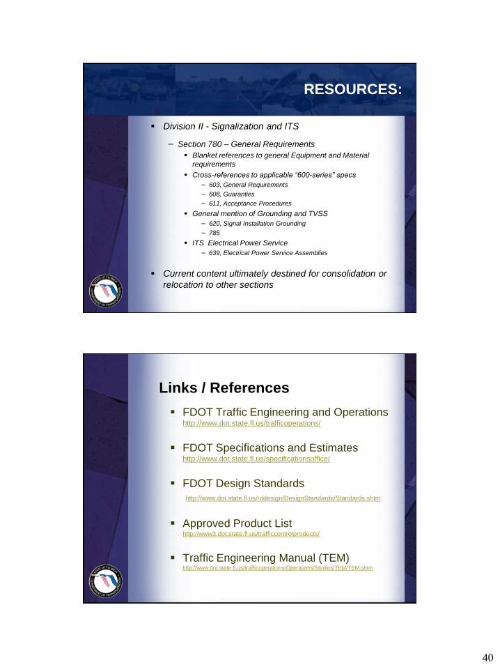
RESOURCES:
Division II - Signalization and ITS
− Section 780 – General Requirements
Blanket references to general Equipment and Material
requirements
Cross-references to applicable “600-series” specs
− 603, General Requirements
− 608, Guaranties
− 611, Acceptance Procedures
General mention of Grounding and TVSS
− 620, Signal Installation Grounding
− 785
ITS Electrical Power Service
− 639, Electrical Power Service Assemblies
Current content ultimately destined for consolidation or
relocation to other sections
Links / References
FDOT Traffic Engineering and Operations http://www.dot.state.fl.us/trafficoperations/
FDOT Specifications and Estimates http://www.dot.state.fl.us/specificationsoffice/
FDOT Design Standards
http://www.dot.state.fl.us/rddesign/DesignStandards/Standards.shtm
Approved Product List http://www3.dot.state.fl.us/trafficcontrolproducts/
Traffic Engineering Manual (TEM) http://www.dot.state.fl.us/trafficoperations/Operations/Studies/TEM/TEM.shtm

41
Links / References
Florida Intersection Design Guide
www.dot.state.fl.us/rddesign/FIDG-Manual/FIDG2007.pdf
Plans Preparation Manual http://www.dot.state.fl.us/rddesign/PPMManual/PPM.shtm
Master Pay Item List / WebGate
FHWA Manual on Uniform Traffic Control
Devices (MUTCD) http://mutcd.fhwa.dot.gov/pdfs/2009/pdf_index.htm
FDOT Central Office
Traffic Engineering and Operations
Gene Glotzbach, P.E.
Ron Meyer
Carlo Adair, P.E.
Future Questions?