Embed Size (px)
Citation preview

www.wackerneuson.com
Operator's manual
Floor saw
BFS 1345B, BZ
0203599en 00611.2008


T00940en.fm 3
Important note
EPA-certified engineThis machine is equipped with an EPA-certified engine.Relevant details can be found in the instructions of the engine manu-facturer.
WarningThe engine's exhaust fumes contain chemicals which are known to theState of California to cause cancer, congenital defects or other repro-ductive anomalies.

T00940en.fm 4

5
Foreword1. Foreword
For your own safety and protection from bodily injuries, carefully read,understand and follow the safety information in this manual.
Please operate and maintain your Wacker Neuson machine in accor-dance with the instructions in this operator's manual. Your WackerNeuson machine will reward you with troublefree operation and a highdegree of availability.
Defective components must be replaced immediately.
All rights, especially the right for copying and distribution, are reserved
Copyright 2008 by Wacker Construction Equipment AG
No part of this publication may be reproduced in any form or by anymeans, electronic or mechanical, including photocopying, without ex-press permission in writing from Wacker Construction Equipment AG.
Any type of reproduction, distribution or saving on data carriers of anytype or method not authorized by Wacker Neuson represents an infringe-ment of valid copyrights and will be prosecuted. We expressly reservethe right to make technical modifications - even without special notice -which aim at further improving our machines or their safety standards.

Table of contents
6
1. Foreword 5
2. Safety information 8
2.1 General instructions ..............................................................................82.2 Operation ...............................................................................................82.3 Safety checks ......................................................................................102.4 Maintenance ........................................................................................112.5 Transport .............................................................................................112.6 Maintenance checks ............................................................................11
3. Technical data 12
4. Description 13
4.1 Application ...........................................................................................134.2 Maximum permissible tilt .....................................................................134.3 Functional description .........................................................................144.4 General instructions for use for diamond-edged cutting blades ..........15
5. Transport to the worksite 16
6. Operation 17
6.1 Adjusting the handle ............................................................................176.2 Adjusting / Aligning the guide wheel ....................................................186.3 Cutting depth setting ...........................................................................196.4 Depth of cut indicator ..........................................................................196.5 Water tank ...........................................................................................206.6 Parking brake ......................................................................................216.7 Assembling the cutting blade ..............................................................226.8 Disassembling the cutting blade ..........................................................236.9 Checking the motor before starting .....................................................246.10 Starting the engine ..............................................................................256.11 Engine operation .................................................................................276.12 Switch off the engine ...........................................................................28

Table of contents
7
7. Maintenance 29
7.1 Maintenance schedule ........................................................................297.2 Checking engine oil level .....................................................................307.3 Changing the engine oil .......................................................................307.4 Cleaning the air cleaner ......................................................................317.5 Cleaning the screws, nuts and bolts ....................................................317.6 Tightening the belt ...............................................................................327.7 Changing the belt ................................................................................337.8 Checking the spark plug ......................................................................34
8. Signs 35
EC Declaration of Conformity 37
DIN EN ISO 9001 Certificate 39
Safety information
SV00075en.fm 8
2. Safety informationfor floor saws with combustion engine drive
2.1 General instructions
2.1.1 Floor saws may only be operated by persons who∗ are at least 18 years of age,∗ are physically and mentally fit for this job,∗ have been instructed in operating floor saws and have proved their
abilities to the employer and∗ may be expected to carry out the job they are charged with carefully.
They must have been assigned to work on the floor saws by the com-pany.
2.1.2 Floor saws may only be operated taking the operator's manual of themanufacturer and this safety information into account.
2.1.3 The persons charged with the operation of floor saws must be madefamiliar with the necessary safety measures relating to the machine. Incase of extraordinary uses, the employer shall give the necessary ad-ditional instructions.
2.1.4 This machine generates noise that exceeds the country-specific per-missible noise levels (individual rating level). It may therefore be nec-essary to wear ear protection.
2.2 Operation
2.2.1 The function of operation levers or elements must not be influenced orrendered ineffective.
2.2.2 Use only cutting blades that are suitable for the peripheral speed or thespeed of the machine.
2.2.3 Always use the correct cutting blade for the material to be cut.2.2.4 Do not touch hot parts as they can cause burns!2.2.5 Particularly when starting the engine you have to make sure that the
cutting blade does not come into contact with anything.2.2.6 Never let the machine run unattended.2.2.7 The operator must not leave the machine during operation.2.2.8 Before the operator leaves the floor saw unattended, he must switch
off the engine and take precautions to prevent the machine fromslipping or falling over.

Safety information
SV00075en.fm 9
2.2.9 Open flames and smoking are strictly prohibited in the immediatevicinity of this machine.
2.2.10 The tank lid must be tightly secured. When the motor is switched off,the fuel tap - if there is one - must be closed. When transported overlong distances, the tank of gasoline or mixed gasoline driven enginesmust be completely emptied.Leaking fuel tanks can lead to explosions and therefore must be re-placed immediately.
2.2.11 The tank may only be filled when the motor is switched off and the fuelmust not make contact with hot parts or fall on the ground.
2.2.12 Safety in the work areaThere may be no electric lines, gas lines, water lines or pipes in thework area.
2.2.13 No operation in closed quartersDo not operate the machine in closed quarters!In partially closed rooms such as tunnels, drifts or deep trenches, en-sure sufficient ventilation by, for example, providing a powerful exhaustair fan.Danger of poisoning! Do not inhale exhaust fumes. They contain toxiccarbon monoxide that can lead to unconsciousness or death.
2.2.14 Floor saws must be operated in wet-cutting operation to preventharmful particulate matter from developing. During wet-cuttingoperation, a sufficient water supply must always be ensured.
2.2.15 Do not operate this machine in areas where explosions may occur.2.2.16 Prior to working near easily combustible material, ensure that supplies
of water or a fire extinguisher are readily available for use.2.2.17 Always wear eye protection, ear protection, working gloves, hard hat,
close-fitting clothing and hard-toed shoes during work. Shoes and legwear must not be open in order to protect the wearer from flyingsparks. In the case of dusty ambient air, breathing protection must alsobe worn.
2.2.18 Prevent the machine from turning to the side in the case of cuts,thrusts, blows or falls. Otherwise, the cutting blade may be damaged.Only cut materials on the edge of the blade.
2.2.19 Prior to commissioning, fix the protective hood in protective position.2.2.20 During work, no one is to come near the machine.2.2.21 Prior to making adjustments, the operator must stop the cutting blade.2.2.22 Work in a calm and composed manner. Prevent risks to others by
exercising caution.2.2.23 Do not process loose materials (e.g. paving stones).

Safety information
SV00075en.fm 10
2.3 Safety checks
2.3.1 Floor saws may only be operated with all safety devices installed.2.3.2 Before starting operation, the operator has to check that all control and
safety devices are functioning properly.2.3.3 Prior to starting the cutting operation, the following have to be checked
on a daily basis:∗ Proper condition of the cutting blade.∗ Tightness of the cutting blade.∗ Damage and wear of the operating and safety equipment.
2.3.4 If defects on the safety devices or other defects impairing theoperational safety of machine are observed, the supervisor must beinformed immediately.
2.3.5 If there are defects jeopardizing operational safety, the machine has tobe switched off immediately.

Safety information
SV00075en.fm 11
2.4 Maintenance2.4.1 Only use original spare parts. Alterations to this machine, incl. adjust-
ments of the maximum engine speed set by the manufacturer may onlybe carried out with the express permission of Wacker Neuson. In caseof non-observance, all liability shall be refused.
2.4.2 Switch off the motor during maintenance work and remove the sparkplug terminal cap (if there is one), in order to avoid an unintentionalstart. This procedure may only be waived if the work cannot be carriedout when the motor is switched off.
2.4.3 Exercise caution when checking the ignition system. The electronicignition creates a very high voltage.
2.4.4 As soon as maintenance and repair jobs have been completed, allsafety devices must be properly reinstalled.
2.4.5 It is not permitted to tilt the machine for maintenance work.2.4.6 In order to prevent malfunctions, the floor saw should be cleaned using
water after each use.
2.5 Transport
2.5.1 Prior to transport, the cutting blade must be removed and the floor sawmust be put in the lowest cutting position.
2.5.2 For the loading and transportation of floor saws with hoisting gear,suitable sling chains must be secured at the relevant fixing point.
2.5.3 Loading ramps must be able to bear the load and be in a stableposition. Make sure that no one can be endangered if the machineslips away or tips over, or if machine parts suddenly move upward ordownward.
2.5.4 When floor saws are being transported in vehicles, precautions haveto be taken to ensure that they do not slip and fall over.
2.6 Maintenance checks
2.6.1 According to the conditions and frequency of use, floor saws must bechecked for safe operation at least once a year by skilled technicians,such as those employed by Wacker Neuson service stations, andrepaired if necessary.
Please observe the appropriate rules and regulations valid in your coun-try.

Technical data
TD00737en.fm 12
3. Technical data
BFS 1345 AB
BFS 1345 ABZ
BFS 1345 B
BFS 1345 BZ
Item no. 00087640610141 0610242 0008909
0610142 0610243
Length x Width x Height mm (in): 1,160 x 568 x 1,078 (45.67 x 22.36 x 42.44)
Weight kg (lb): 95 (209) 96 (212) 95 (209) 96 (212)
Powertrain From drive motor via belt to cutting blade
Max. cutting blade diameter mm (in): 450 (17.72)
Min. cutting blade diameter mm (in): 350 (13.78)
Max. cutting width mm (in): 12 (0.47)
Center bore mm (in): 25.4 (1.00)
Max. cutting depth cm (in): 17 (6.69)
Peripheral blade speed at ø 350 ø 400 ø 450(at rated engine speed)
m/s (ft/s):m/s (ft/s):m/s (ft/s):
40.3 (132)46.1 (151)51.8 (170)
Operating blade speed(at rated engine speed)
rpm: 2,200
Water tank capacity l (gal): 32 (8.45)
Drive motor Air-cooled, single-cylinder, four-stroke gasoline engine
Engine displacement cm3 (in3): 389 (23.73) 404 (24.65)
Rated speed rpm: 3,600
Rated power (*) kW/HP: 9.6/13 9.9/13.5
Fuel Normal gasoline, also unleaded
Fuel consumption(at rated output)
l/h(gal/h):
4.3(1.14)
Fuel tank capacity l (gal): 6.5 (1.72) 7.0 (1.85)
Oil capacity l (gal): 1.1 (0.29) 1.2 (0.32)
Oil specification SAE 15W-40
Spark plug Type: NGK BPR6ES
(*) Corresponds to the installed effective power in accordance with Directive 2000/14/EC
Sound pressure level at operator's station
LPA: 97 dB(A)
Weighted effective acceler-ation value according to EN ISO 5349
m/s2:6.2 7.5

Description
T01067en.fm 13
4. Description
4.1 Application
∗ Cutting expansion joints in concrete and asphalt surfaces.∗ Repair work on streets, e.g. cutting out damaged areas in asphalt and
concrete.∗ Straightening blacktops and concrete surfaces.∗ For demolition jobs and refurbishment of old buildings.∗ Sawing off precast concrete parts.∗ Expansion joints and installation channels in floors.∗ Laying induction loops and cables in signal installations.
4.2 Maximum permissible tilt
The maximum permissible tilt applies to the engine level.

Description
T01067en.fm 14
4.3 Functional description
The floor saw must only be operated in a forward direction (see arrow).The drive motor (1) attached to the frame drives the cutting blade viathe belt (2).The cutting blade can be infinitely adjusted by means of a crankhandle (3), 1 turn corresponds to a cutting depth adjustment of 5 mm.The cutting blade guard (4) can be swiveled upwards to make it easierto assemble and disassemble the cutting blade.Furthermore, the cutting blade guard can be connected with the watertank by means of a hose (5) and an adapter.Wetting the cutting blade with water prevents dust from developing.The adapter on the water hose allows the connection of an externalwater supply.The drive motor speed can be infinitely adjusted by means of the gasthrottle lever (6), whereby the optimum cutting blade speed is reachedwhen the drive motor is operated at full throttle.To facilitate the starting procedure, the drive motor is equipped with achoke.

Description
T01067en.fm 15
4.4 General instructions for use for diamond-edged cutting blades
∗ Never use a cutting blade with a larger diameter than necessary in or-der to cut a certain depth.
∗ If the cutting blade comes to a standstill, remove it from the cut beforestarting the machine again. If the cutting blade comes to a standstill inthe cut, check whether the belt is tightened adequately. Check the ten-sion screw and make sure that it is tightened properly.
∗ Cut in a straight line. Mark the cutting line clearly in such a way that theoperational personnel can follow it easily. This is to ensure that thefloor saw machine does not need to be redirected from one side to theother (avoid cutting tight curves).
∗ Sufficient drive power is essential! When cutting, work at full throttle.∗ Caution on steep tracks and levels! The machine must not exert lateral
force against the blade.∗ Never exceed the maximum speeds (imprinted on cutting blade)!∗ Use a suitable diamond-edged cutting blade for the material to be cut
(asphalt, concrete ...). Wacker Neuson offers an extensive range of di-amond-edged cutting blades in different qualities.
∗ Do not cut into the gravel area using diamond-edged cutting blades.When cutting on the edge of the track or when cutting two different ma-terials (cutting in the joint area), uneven wear is possible. Check care-fully for irregularities (reinforcements etc.) in the material to beprocessed. These can overload the cutting blade very quickly. Whenstarting cutting operations, work carefully and with a low down speed.
∗ Do not process loose materials (e. g. paving stones).

Transport to the worksite
T01111en.fm 16
5. Transport to the worksite
Requirements:∗ When transporting the floor saw, use only suitable hoisting gear with a
minimum load-bearing capacity of 150 kg.∗ Always turn off the motor during transportation!∗ Empty the water tank!∗ Remove the cutting blade prior to transport. Set the lowest cutting po-
sition on the floor saw.∗ Remove the water tank and attach the hoisting gear on the transport
strap (1) for lifting.∗ If you transport the floor saw on the cargo area of a vehicle, strap it
down securely on the special safety bar.∗ Fold the guide wheel to the top and the handles to the front (or the stir-
rup handle to the top).∗ Handles, guide wheel and other operating controls must not be used
as attachment points.
Note: Also observe the regulations in the chapter Safety information.

T01110en.fm 17
Operation6. Operation
6.1 Adjusting the handle
6.1.1 Handle
The width and height of the handles can be adjusted according to theuse and the body height of the operator. To do this, release theclamping lever (1) and apply it in the new position.
6.1.1 Stirrup handle (alternative version)
The height of the stirrup handle can be adjusted according to the useand the body height of the operator.Loosen the knurled screws (1) on both sides, swivel the handle to thedesired position and retighten the two knurled screws.

Operation
T01110en.fm 18
6.2 Adjusting / Aligning the guide wheel
6.2.1 Adjusting the guide wheelThe guide wheel is designed to help the operator in making long,straight cuts. The guide wheel can be exactly adjusted to the cuttingblade by loosening the jam nut (1) and turning the screw (2).
6.2.2 Aligning the guide wheelTo do this, make a cut of approx. 2 m length on a flat surface and withthe minimum cutting depth. Then pull back the machine without lateralforce. Then you can align the guide wheel exactly with the cut.

T01110en.fm 19
Operation6.3 Cutting depth setting
With the crank (1) you can set the cutting depth precisely. One turnchanges the cutting depth by exactly 5 mm. Turn the crank in theclockwise direction to increase the cutting depth and turn it in thecounterclockwise direction to reduce the cutting depth.Note: You can also insert the supplied tool into the receptacle (2) nearthe crank and thus prevent an unintentional change of the cuttingdepth.
6.4 Depth of cut indicator
You can use the indicator to check the cutting depth currently set. Itfeatures a cm-scale and an inch-scale. You have to adjust it to thediameter of the blade currently installed to obtain the correct value. Todo this, turn the crank (1) until the blade touches the ground, loosenthe clamp (2) and push the sleeve (3) with the scale up to the bottomof the sleeve. Then tighten the clamp (2) again.

Operation
T01110en.fm 20
6.5 Water tank
The floor saw features an integrated, removable water tank (1).To fit the water tank, attach the retaining clamp (2) and tighten it withthe strap (3).To remove the water tank or to attach an external water supply, youcan disconnect the hose on two different spots (4).The amount of water can be regulated or stopped (5).
Note: You should remove the water tank if the machine is connected to anexternal water supply.

T01110en.fm 21
Operation6.6 Parking brake
6.6.1 Integrated parking brakeThe machine features an integrated parking brake.The front wheels are automatically blocked in transport position(lowest cutting position without a cutting blade) or if the maximumcutting depth is exceeded.
6.6.2 Manual parking brake (accessories)
Press the pedal (1) down to block the right rear wheel. Push the pedalupwards for brake release.Check the tight fit of the parking brake and the setting of the pressurescrew (2) at regular intervals. The brake must securely block the wheelat least on a 10° slope. Adjust the pressure screw if necessary.

Operation
T01110en.fm 22
6.7 Assembling the cutting blade
6.7.1 Checking a new cutting blade:∗ The blade type must be suitable for the material to be cut. Observe the
peripheral speed, refer to the "Technical data"!∗ The arbor diameter of the cutting blade must precisely fit the shaft to
ensure smooth blade running.∗ The cutting blade must be undamaged.
Observe the correct direction of rotation of the cutting blade! Thatmeans the rotational direction mark on the cutting blade mustcorrespond with the rotational direction mark on the cutting bladeguard.
6.7.2 Proceed as follows for the assembly of the cutting blade:
1. Fold up the cutting blade guard (1).
2. Prior to the assembly of the cutting blade, clean the spring washersand the locking pin and check them for damage.
3. Attach cutting blade and spring washer on the shaft.
4. Tighten the hexagonal bolt firmly. To do this, apply counter pressureon the spanner surfaces of the cutting shaft.
5. Fold down the cutting blade guard.
Starting the machine is only permitted with a water hose connectedand the water supply turned on.

T01110en.fm 23
Operation6.8 Disassembling the cutting blade
Proceed as follows for the disassembly of the cutting blade:
1. Turn off the engine (2) and the water supply (3).
2. Turn the crank (4) in the counterclockwise direction until the bladeis clear of the ground.
3. Fold up the cutting blade guard (1).
4. Loosen the hexagonal bolt. To do this, apply counter pressure onthe spanner surfaces of the cutting shaft.
5. Remove the spring washer and the cutting blade.
6. Fold down the cutting blade guard.
Store the spring washer and the hexagonal bolt in a clean place wherethey cannot become dirty. Assemble both parts for the transport of themachine!

Operation
T01110en.fm 24
6.9 Checking the motor before starting
6.9.1 Engine oilSwitch off the engine.Prior to checking the engine oil level or refilling engine oil, make surethat the engine bolting level is aligned horizontally.
∗ Remove the oil filler cap (oil level indicator).∗ If the oil level is below the lower filling mark on the dip stick, add suit-
able engine oil until the oil reaches the edge of the filler neck.∗ An oil change is required if the engine oil is dirty.∗ Only use high-quality engine oil, see Technical Data.
The engine is automatically switched off when the oil level falls belowa specific level. If this is the case, the engine can only be started afterengine oil has been refilled.
6.9.2 FuelDo not smoke during refueling and make sure that there are no openflames or sparks in the immediate vicinity.
∗ Turn off the engine and open the fuel tank cap.∗ Only use leadfree fuel.∗ Close the fuel tap before the fuel tank is filled with fuel.∗ Always use the fuel filter when refilling fuel.∗ Wipe off any spilled fuel before starting the engine.
Oil levelindicator
Upper level mark
Lower level mark

T01110en.fm 25
Operation6.10 Starting the engine
The cutting blade must not be in contact with the ground.
1. Switch the main switch (1) to "I".
2. Open the fuel tap..
3. Shift the throttle lever (2) to approximately 1/3 of the full throttleposition.
Close
Close
Open
Slow
Throttle lever (2)Fast
Start position
Close

Operation
T01110en.fm 26
4. Close the choke.
∗ If the engine is warm or at high ambient temperatures, open the chokeapproximately half way or fully.
∗ If the engine is cold or at low ambient temperatures, close the choke.
5. Recoil starter
∗ Slowly pull the recoil starter handle until you can feel resistance(compression stroke). Return the recoil starter handle to its originalposition and pull with force. Do not pull out the entire length of the rope.
∗ As soon as the engine has started, rewind the starter rope by slowlyreturning the recoil starter handle to its original position.
6. Choke
∗ After the engine has been started, slowly open the choke and thenleave it in the fully open position.
∗ If the engine is cold or at low ambient temperatures, never fully openthe choke immediately after the engine has been started or the enginewill stall.
Pull quickly
Open

T01110en.fm 27
Operation6.11 Engine operation
After the engine has started, shift the throttle lever to low (L) enginespeed and allow the engine to warm up for a few minutes.
Slowly shift the throttle lever towards the (H) position for high enginespeed in order to set the required engine speed.
Note: If no high engine speed is required, shift the throttle lever back tooperate the engine at idle speed in order to save fuel and extend the servicelife of the engine.

Operation
T01110en.fm 28
6.12 Switch off the engine
6.12.1 To turn off the engine in the event of an emergency, switch the mainswitch (1) to "0". Under normal circumstances, proceed as follows:
1. Shift the throttle lever (2) to the (L) position for low engine speed andallow the engine to operate at idle speed for a short time beforeswitching it off.
2. Switch the main switch (1) to "0".
3. Close the fuel tap.
4. Slowly pull the recoil starter handle until you feel resistance andthen return the recoil starter handle to its original position.
Note: This procedure is necessary in order to prevent humid ambient airfrom entering the combustion chamber.
6.12.2 Switching off the engine via the fuel tapClose the fuel tap and wait until the engine stalls. Never leave fuel inthe carburetor over a long period of time while the engine is switchedoff. Otherwise, the fuel channels in the carburetor become blocked bydirt which results in faulty operation.
2
Close
Close
Open
Recoil starter handle

Maintenance
T01071en.fm 29
7. Maintenance
7.1 Maintenance schedule
Component Maintenance work Maintenance interval
Machine Check for signs of damage and wear – change, if neces-sary the components.
Before operationSafety devices
Main switch Check for proper functioning – change, if necessary.
Air cleaner- Check for external damage and a tight fit.- Check foam and filter element – clean or replace, if nec-essary.
8 hours (daily)
Fuel - Check the tank cap for leakage – change, if necessary.- Check the fuel level – add oil as needed.
Drive motorMonitoring of:- Excessive vibrations, operating noise.- Engine oil and fuel leaks.
Engine oil Check the oil level – add oil as needed.
Miscellaneous
- Check the cutting blade for damage and tightness – re-place or tighten, if necessary.- Check the direction of rotation arrow of the cuttingblade.- Check that the height adjustment moves freely. - Check the water supply.
Engine oil Initial oil change. 20 hours
Air cleaner Clean – change, if necessary.
50 hours (weekly)Belt Check tension and wear – change, if necessary.
Spark plug Clean, set electrode gap 0.7-0.8 mm.
Engine oil Change.
Fuel filter Have this replaced by Wacker Neuson service. 200 hours
Spark plug Change.300 hours (annually)
Valve clearance Have this repaired by Wacker Neuson service.
Maintenance
T01071en.fm 30
7.2 Checking engine oil level
∗ Switch off the engine.∗ Align the engine bolting level horizontally.∗ Remove any dirt around the oil level dipstick.∗ Remove the oil level dipstick and wipe it with a clean, lint-free cloth.∗ Screw the oil level dipstick all the way back in and pull it out again.∗ Check: The motor oil level must be between the lower and upper
marks.∗ If necessary, pour new engine oil into the opening until the upper mark
is reached on the oil level dipstick (see chapter Technical data for oiltype).
∗ Screw in the oil level dipstick and tighten it by hand.
7.3 Changing the engine oil
The work area should be covered with a waterproof sheet to protect thefloor (protection of the environment).
∗ Align the engine bolting level horizontally.∗ Bring the engine to a hand warm temperature, either by letting it cool
down or running it until it is warm.∗ Switch off the engine.∗ Place a sufficiently large container under the oil drain hose to catch the
used oil.∗ Remove oil drain hose from the holder.∗ Remove any dirt around the locking screw.∗ Unscrew the cap nut.∗ Let the used oil drain out completely.
Avoid spilling oil. Remove any spilled oil immediately.
∗ Close oil drain hose with cap nut.∗ Attach oil drain hose to the holder.∗ Pour new engine oil (see chapter Technical data) into the opening of
the oil level dipstick until the upper mark is reached on the oil level dip-stick (see Checking engine oil level).
∗ Screw in the oil level dipstick and tighten it by hand.
Dispose of the used oil in accordance with the applicable regulations.
Maintenance
T01071en.fm 31
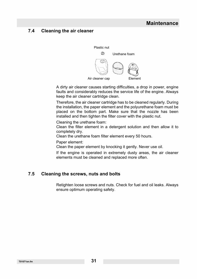
7.4 Cleaning the air cleaner
A dirty air cleaner causes starting difficulties, a drop in power, enginefaults and considerably reduces the service life of the engine. Alwayskeep the air cleaner cartridge clean.Therefore, the air cleaner cartridge has to be cleaned regularly. Duringthe installation, the paper element and the polyurethane foam must beplaced on the bottom part. Make sure that the nozzle has beeninstalled and then tighten the filter cover with the plastic nut.Cleaning the urethane foam:Clean the filter element in a detergent solution and then allow it tocompletely dry.Clean the urethane foam filter element every 50 hours.Paper element:Clean the paper element by knocking it gently. Never use oil.If the engine is operated in extremely dusty areas, the air cleanerelements must be cleaned and replaced more often.
7.5 Cleaning the screws, nuts and bolts
Retighten loose screws and nuts. Check for fuel and oil leaks. Alwaysensure optimum operating safety.
Plastic nut
Air cleaner cap
Urethane foam
Element

Maintenance
T01071en.fm 32
7.6 Tightening the belt
Check the belt in the course of the weekly engine maintenance and re-tighten it as follows, if necessary:
1. Remove the belt guard.
2. Loosen the jam nut (1).
3. Loosen the four fastening nuts of the engine until the engine can bemoved without play.
4. Tighten the belt with the tension screw (2). V-belt tension 700 N (vibration frequency 98 Hz).
5. If necessary, correct the parallel alignment of the engine. As a first step, tighten a fastening nut of the engine and correct thealignment by means of the tension screw (2).
6. Tighten all fastening nuts of the engine as well as the jam nut (1).
7. Mount the belt guard.
Note: The frame is provided with two recesses (3) which can be used tomeasure the parallel alignment of the engine.

Maintenance
T01071en.fm 33
7.7 Changing the belt
1. Remove the belt guard.
2. Loosen the jam nut (1).
3. Loosen the four fastening nuts of the engine until the engine canbe moved without play.
4. Unscrew the bearing flange (6 screws - (4)).
5. Replace the belt (5).
6. Screw on the bearing flange (6 screws - (4)).
7. Tighten the belt with the tension screw (2). V-belt tension 700 N (vibration frequency 98 Hz).
8. If necessary, correct the parallel alignment of the engine. As a first step, tighten a fastening nut of the engine and correct thealignment by means of the tension screw (2).
9. Tighten all fastening nuts of the engine as well as the jam nut (1).
10. Mount the belt guard.
Note: The frame is provided with two recesses (3) which can be used tomeasure the parallel alignment of the engine.

Maintenance
T01071en.fm 34
7.8 Checking the spark plug
∗ Remove any soot deposits from the electrodes of the spark plug using aspark plug cleaner or a wire brush.
∗ Check the spark plug gap and set it to 0.7 - 0.8 mm, if necessary.∗ Select the correct spark plug, see chapter Technical Data.
0.7 - 0.8 mm

Signs
SK00693en.fm 35
8. Signs
1 Cutting depth setting
2 Note- Caution, risk of injury- Read the operator's manual.- Wear a helmet, eye protection and ear protection!- Machine may not be offset with the cutting blade rotating.
3 Sound power level
4 Rotational direction arrow
5 Depth of cut indicator

Signs
SK00693en.fm 36

www.wackerneuson.com
EC Declaration of Conformity
ManufacturerWacker Construction Equipment AGPreußenstraße 41D-80809 München
Product
Conformity assessment procedure acc. to 2000/14/EC, Appendix V.
Guidelines and standardsThis is to certify that this product meets and complies with the relevant regulations and re-quirements of the following guidelines and standards:98/37/EC, 2000/14/EC, 2005/88/EC, 2004/108/EC, EN 55012:2007
Munich, October 2008
Type BFS 1345 AB BFS 1345 ABZ
BFS 1345 B BFS 1345 BZ
Product type Floor saw
Item number 0008764 0610141
0610242 0008909 0610142
0610243
Installed power output [kW] 9.6 9.9
Measured sound power level
dB(A) 106
Guaranteed sound power level
dB(A) 107
Dr. Michael FischerHead of Research and Development
Franz BeierleinHead of product management


Prüf- und Zertifizierungsinstitut VERBAND DER ELEKTROTECHNIK
ELEKTRONIK INFORMATIONSTECHNIK e.V.
C E R T I F I C A T ERegistration-Number: 6236/QM/06.97
This is to certify that the company
Wacker Construction Equipment AGWacker-Werke GmbH & Co. KG
at the following locations
Head Office MunichPreußenstraße 41
80809 Munich
Production plant ReichertshofenKarlsfeld logistics centre
Sales regions with all branches all over Germany
has implemented and maintains a Qality Management System for the following scope:
Machine manufactureConstruction machines
This Q System complies with the requirements of
DIN EN ISO 9001:2000and the requirements of the German and international Road Traffic Act.
This Certificate is valid until 2009-06-05.
VDE Testing and Certification InstituteCertification
Date: 2006-05-30
63069 Offenbach, Merianstraße 28Telefon: +49 (0) 69 83 06-0, Telefax: +49 (0) 69 83 06-555E-Mail: [email protected], http://www.vde-institut.com
The VDE Testing and Certification Institute is accredited by DAR AccreditationBodies according to DIN EN ISO 17020 and DIN EN ISO 45012 and notified in the EUunder ID.No. 0366.
TGA-ZM-09-92-00KBA-ZM-A 00021-97
DIN EN ISO 9001 Certificate

Wacker Construction Equipment AG – Preußenstraße 41 – 80809 München – Deutschland – Tel.: +49-(0)89-354 02-0 – Fax: +49-(0)89-354 02-390Wacker Corporation – P.O. Box 9007 – Menomonee Falls, WI 53052-9007 – USA – Tel.: +1(1)262-255-0500 – Fax: +1(1)262-255-0550 – Support: 800-770-0957Wacker Machinery (HK) Ltd.– Skyline Tower, Suite 2303, 23/F – 39 Wang Kwong Road, Kowloon Bay – Hong Kong – Tel.: +852-3188-5506, Fax: +852-2406-6021