Embed Size (px)
Citation preview

Flomate Mains Boost Pump
Installation & Maintenance Instructions
Please leave this instruction booklet with the owner as
it contains important guarantee, maintenance and safety
information
CE compliant product
PATENT APPROVED
GB 2494485 A

- 2 -
Cont ...
PRODUCT DESCRIPTIONElectric motor driven peripheral pump with bypass, complete with an automatic control
system consisting of flow switch and electronic control.
APPLICATIONThe Flomate is a mains booster pump with an automatic control system for domestic
use, designed to assist the pressure from the mains supply, where the mains pressure is
insufficient. This unit requires a minimum unassisted supply flow of 0.6 l/min to operate.
The pump is limited to producing a maximum flow of not greater than 12 l/min, and a
maximum pressure of 3.0 bar.
When the flow/pressure from the rising main exceeds the pump output, the patented
applied for integral bypass will direct the water into the system as normal.
The Flomate mains booster is a patent granted design.
Please note the following warning signs.
Warning of possible electrical hazard.
Possible danger to personnel or important installation requirement.
All the safety and operating instructions in this booklet must be
followed.
The pump must not be used for any other application without the
written consent of Stuart Turner Limited.
The pump must be installed by a qualified person.
The pump is not suitable for heavy commercial/industrial
applications.
The installation must comply with the latest Building Regulations,
Wiring Regulations (BS 7671) and Water Supply Regulations (see
notes).
This appliance can be used by children aged from 8 years and
above and persons with reduced physical, sensory or mental
capabilities or lack of experience and knowledge if they have been
given supervision or instruction concerning use of the appliance
in a safe way and understand the hazards involved. Children shall
not play with the appliance. Cleaning and user maintenance shall
not be made by children without supervision.
Children should be supervised to ensure that they do not play with
the appliance.
Notes
This product must be installed in accordance with the current
Water Supply (Water Fittings) Regulations.
Under no account should the internal flow restrictor be removed,
or replaced with an alternative design.

- 3 -
Cont ...
The flow restrictor must be replaced every 2 years.
Care must be taken to ensure the maximum pressure generated
by the pump combined with the incoming mains water pressure
does not exceed the pumps maximum operating pressure of 6 bar.
Please read installation details carefully as they are intended to ensure this
product provides long, trouble free service. Failure to install the unit in
accordance with the installation instructions will lead to invalidation of the
warranty.
STORAGEIf this product is not to be installed immediately on receipt, ensure that it is stored in a dry,
frost and vibration free location in its original packaging.
CONTENTS Page
Checklist . . . . . . . . . . . . . . . . . . . . . . . . . . . . . . . . . . . . . . . . . . . . . . . . . . . . . . . . 4
Important Facts - read before commencing installation . . . . . . . . . . . . . . . . . . . 5
Location . . . . . . . . . . . . . . . . . . . . . . . . . . . . . . . . . . . . . . . . . . . . . . . . . . . . . . . . 6
Electrical Installation . . . . . . . . . . . . . . . . . . . . . . . . . . . . . . . . . . . . . . . . . . . . . . . 8
Priming . . . . . . . . . . . . . . . . . . . . . . . . . . . . . . . . . . . . . . . . . . . . . . . . . . . . . . . . . 10
Maintenance . . . . . . . . . . . . . . . . . . . . . . . . . . . . . . . . . . . . . . . . . . . . . . . . . . . . . 10
Technical Specifi cation . . . . . . . . . . . . . . . . . . . . . . . . . . . . . . . . . . . . . . . . . . . . . 11
Trouble Shooting . . . . . . . . . . . . . . . . . . . . . . . . . . . . . . . . . . . . . . . . . . . . . . . . . 12
Guarantee . . . . . . . . . . . . . . . . . . . . . . . . . . . . . . . . . . . . . . . . . . . . . . . . . . . . . . . 14

- 4 -
Cont ...
CHECKLIST
Item Description Qty
Pump 1
Your product may vary slightly from the picture above.
A
Fig. 1
IMPORTANT: With the pump
removed from its packaging
check for any damage prior to
installation. If any damage is
found contact Stuart Turner Ltd
within 24 hours of receipt.
A
G ¾ compression fitting
with isolating valve and
seal (not supplied) (or
alternative)
- 5 -
Cont ...
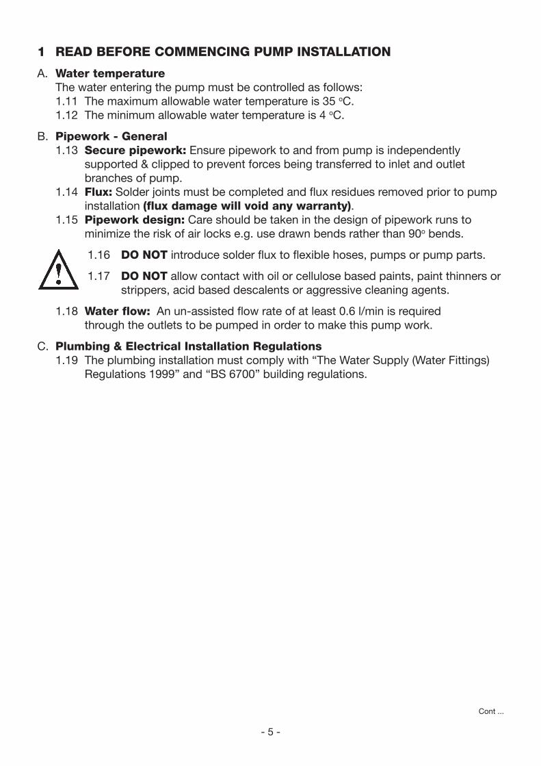
1 READ BEFORE COMMENCING PUMP INSTALLATION
A. Water temperature
The water entering the pump must be controlled as follows:
1.11 The maximum allowable water temperature is 35 oC.
1.12 The minimum allowable water temperature is 4 oC.
B. Pipework - General
1.13 Secure pipework: Ensure pipework to and from pump is independently
supported & clipped to prevent forces being transferred to inlet and outlet
branches of pump.
1.14 Flux: Solder joints must be completed and flux residues removed prior to pump
installation (flux damage will void any warranty).
1.15 Pipework design: Care should be taken in the design of pipework runs to
minimize the risk of air locks e.g. use drawn bends rather than 90o bends.
1.16 DO NOT introduce solder flux to flexible hoses, pumps or pump parts.
1.17 DO NOT allow contact with oil or cellulose based paints, paint thinners or
strippers, acid based descalents or aggressive cleaning agents.
1.18 Water flow: An un-assisted flow rate of at least 0.6 l/min is required
through the outlets to be pumped in order to make this pump work.
C. Plumbing & Electrical Installation Regulations
1.19 The plumbing installation must comply with “The Water Supply (Water Fittings)
Regulations 1999” and “BS 6700” building regulations.
- 6 -
Cont ...
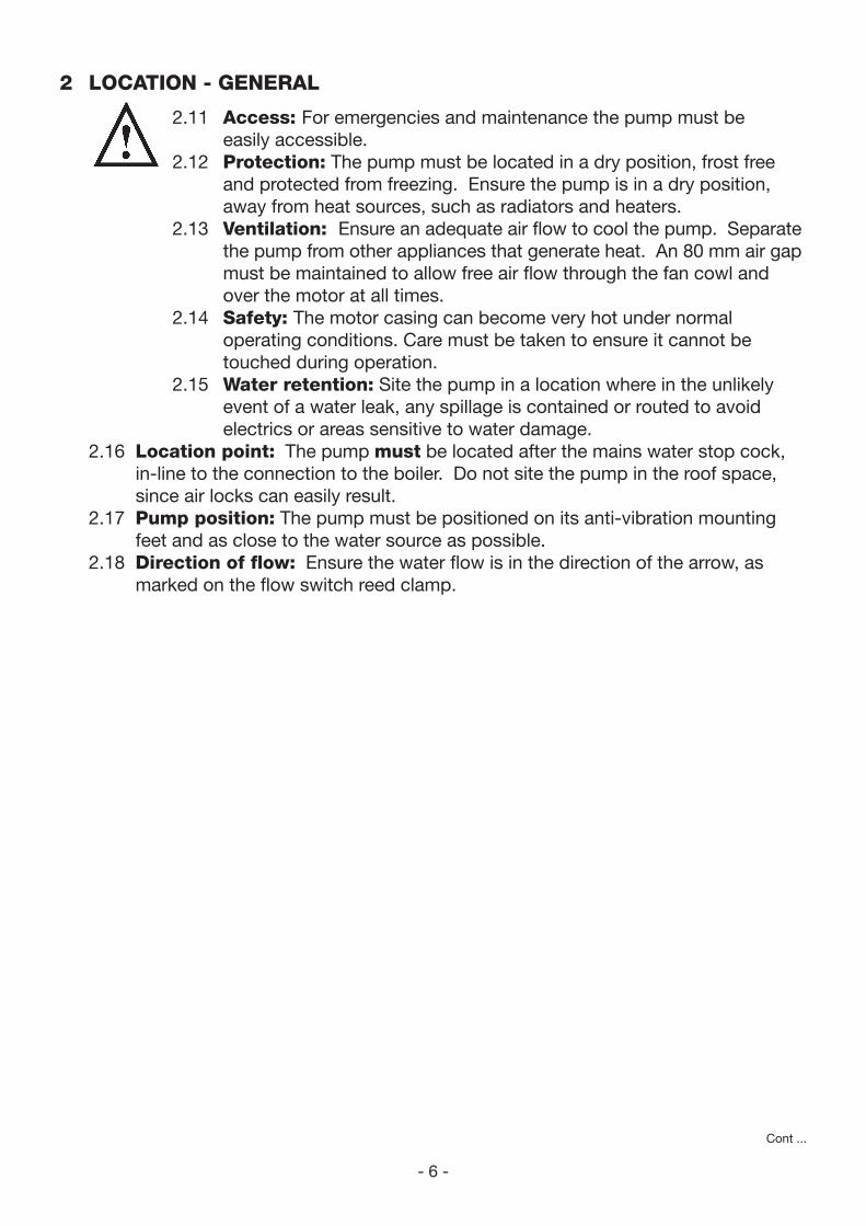
2 LOCATION - GENERAL
2.11 Access: For emergencies and maintenance the pump must be
easily accessible.
2.12 Protection: The pump must be located in a dry position, frost free
and protected from freezing. Ensure the pump is in a dry position,
away from heat sources, such as radiators and heaters.
2.13 Ventilation: Ensure an adequate air flow to cool the pump. Separate
the pump from other appliances that generate heat. An 80 mm air gap
must be maintained to allow free air flow through the fan cowl and
over the motor at all times.
2.14 Safety: The motor casing can become very hot under normal
operating conditions. Care must be taken to ensure it cannot be
touched during operation.
2.15 Water retention: Site the pump in a location where in the unlikely
event of a water leak, any spillage is contained or routed to avoid
electrics or areas sensitive to water damage.
2.16 Location point: The pump must be located after the mains water stop cock,
in-line to the connection to the boiler. Do not site the pump in the roof space,
since air locks can easily result.
2.17 Pump position: The pump must be positioned on its anti-vibration mounting
feet and as close to the water source as possible.
2.18 Direction of flow: Ensure the water flow is in the direction of the arrow, as
marked on the flow switch reed clamp.
- 7 -
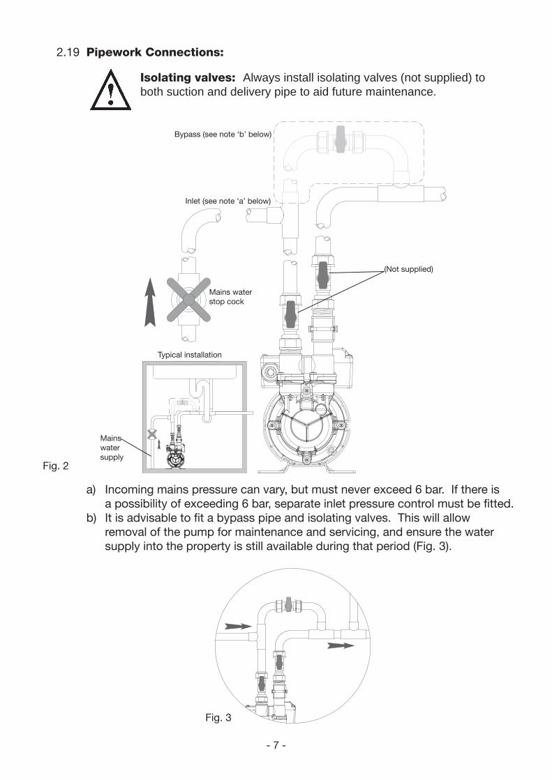
2.19 Pipework Connections:
Isolating valves: Always install isolating valves (not supplied) to both suction and delivery pipe to aid future maintenance.
a) Incoming mains pressure can vary, but must never exceed 6 bar. If there is
a possibility of exceeding 6 bar, separate inlet pressure control must be fitted.
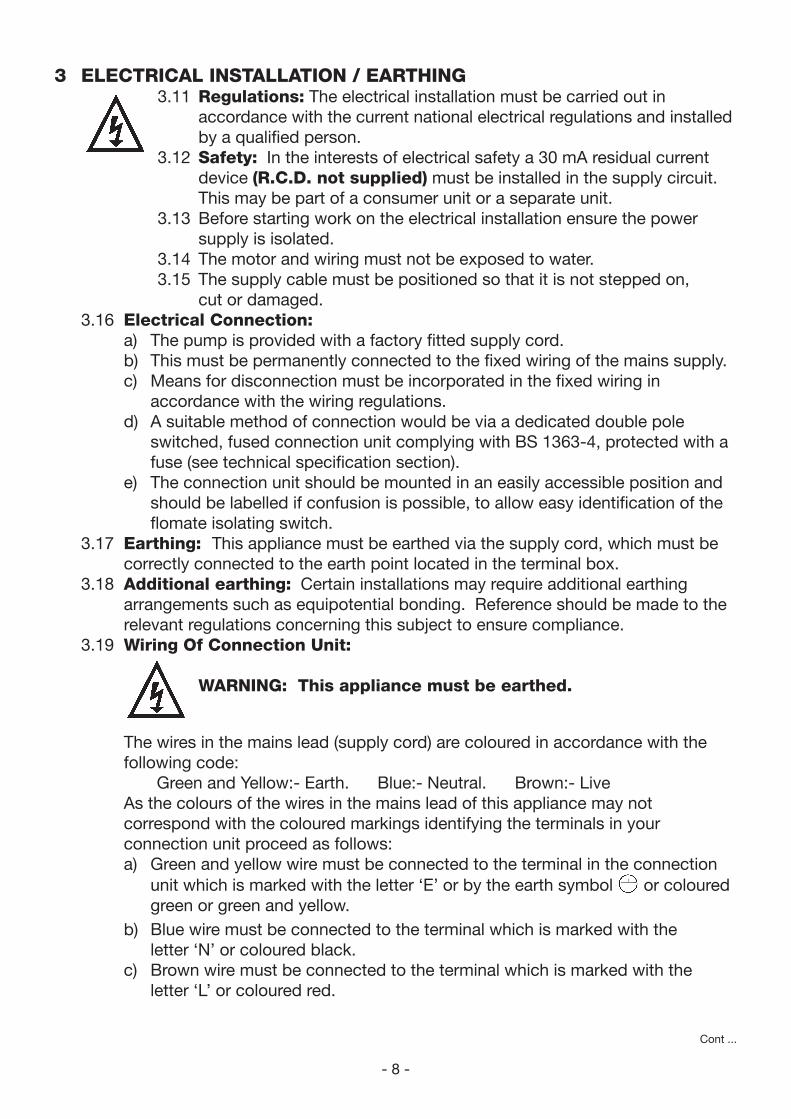
b) It is advisable to fit a bypass pipe and isolating valves. This will allow
removal of the pump for maintenance and servicing, and ensure the water
supply into the property is still available during that period (Fig. 3).
Fig. 3
Fig. 2
Typical installation
Mains water
stop cock
Inlet (see note ‘a’ below)
Mains
water
supply
Bypass (see note ‘b’ below)
(Not supplied)
- 8 -
Cont ...
3 ELECTRICAL INSTALLATION / EARTHING3.11 Regulations: The electrical installation must be carried out in
accordance with the current national electrical regulations and installed
by a qualified person.
3.12 Safety: In the interests of electrical safety a 30 mA residual current
device (R.C.D. not supplied) must be installed in the supply circuit.
This may be part of a consumer unit or a separate unit.
3.13 Before starting work on the electrical installation ensure the power
supply is isolated.
3.14 The motor and wiring must not be exposed to water.
3.15 The supply cable must be positioned so that it is not stepped on,
cut or damaged.
3.16 Electrical Connection:
a) The pump is provided with a factory fitted supply cord.
b) This must be permanently connected to the fixed wiring of the mains supply.
c) Means for disconnection must be incorporated in the fixed wiring in
accordance with the wiring regulations.
d) A suitable method of connection would be via a dedicated double pole
switched, fused connection unit complying with BS 1363-4, protected with a
fuse (see technical specification section).
e) The connection unit should be mounted in an easily accessible position and
should be labelled if confusion is possible, to allow easy identification of the
flomate isolating switch.
3.17 Earthing: This appliance must be earthed via the supply cord, which must be
correctly connected to the earth point located in the terminal box.
3.18 Additional earthing: Certain installations may require additional earthing
arrangements such as equipotential bonding. Reference should be made to the
relevant regulations concerning this subject to ensure compliance.
3.19 Wiring Of Connection Unit:
WARNING: This appliance must be earthed.
The wires in the mains lead (supply cord) are coloured in accordance with the
following code:
Green and Yellow:- Earth. Blue:- Neutral. Brown:- Live
As the colours of the wires in the mains lead of this appliance may not
correspond with the coloured markings identifying the terminals in your
connection unit proceed as follows:
a) Green and yellow wire must be connected to the terminal in the connection
unit which is marked with the letter ‘E’ or by the earth symbol or coloured
green or green and yellow.
b) Blue wire must be connected to the terminal which is marked with the
letter ‘N’ or coloured black.
c) Brown wire must be connected to the terminal which is marked with the
letter ‘L’ or coloured red.
- 9 -
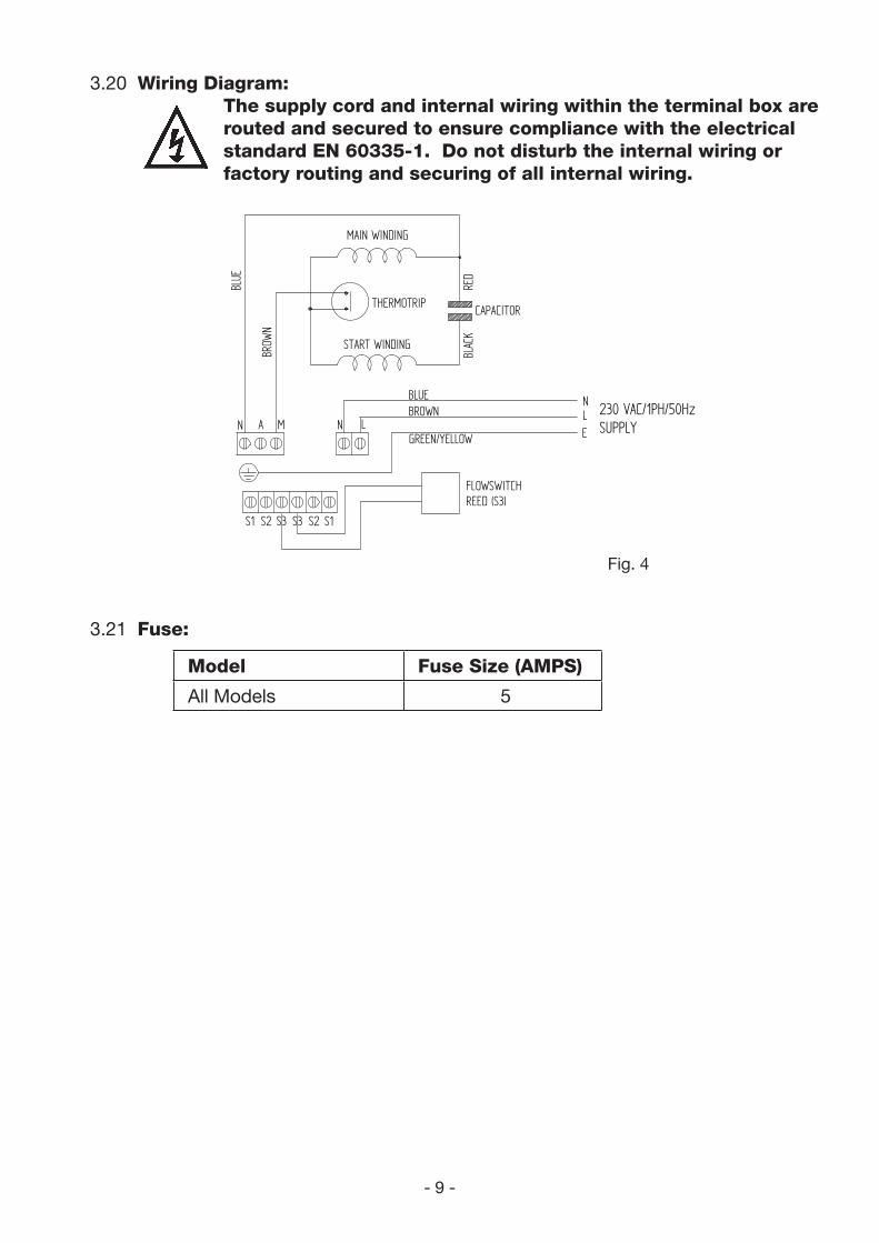
3.20 Wiring Diagram:
The supply cord and internal wiring within the terminal box are
routed and secured to ensure compliance with the electrical
standard EN 60335-1. Do not disturb the internal wiring or
factory routing and securing of all internal wiring.
Model Fuse Size (AMPS)
All Models 5
3.21 Fuse:
Fig. 4
MAIN WINDING
THERMOTRIP CAPACITOR
START WINDING
FLOWSWITCHREED (S3)
BLUE
BROW
N
BLAC
KRE
D
GREEN/YELLOW
BLUEBROWN L
MA
N
N
S2 S3 S3 S2
LE
N
S1S1
230 VAC/1PH/50HzSUPPLY
- 10 -
Cont ...
4 PRIMING4.11 Priming: This pump is self venting. Open the mains stopcock and allow the
pump to fill and vent, please note the pump chamber must be full of liquid at all
times. Seal damage will result if the pump runs dry. Do not run the pump dry.
4.12 Starting:
a) Ensure all outlets are closed, turn power supply ‘on’.
b) Open and close all outlets in turn associated with the pump allowing liquid to
flow from each outlet until all air is purged. As each outlet is opened and
closed the pump will start and stop respectively.
c) Any tap or control valve within the system when opened and closed will now
turn the pump on/off. Check system for leaks, if clear the system is now
operating correctly
d) Carefully check pump and pipework for leaks whilst pump running and
stationary before leaving the installation unattended.
4.13 For Further Technical Support: Phone the Stuart Turner PumpAssist team
on +44 (0) 844 98 000 97. Our staff are trained to help and advise you over the
phone.
Note: When pumps are installed in another manufacturers original equipment,
please contact the manufacturer for advice.
5 MAINTENANCE5.11 Disconnect electrical supply before working on pump.
5.12 Turn off liquid supplies to the pump and release pressure by opening outlets
before attempting maintenance.
5.13 The flow restrictor inside the pump must be replaced every 2 years (contact
Stuart Turner Ltd).
5.14 No other routine maintenance is required.
5.15 After maintenance is completed, refer to Section 4 - Commissioning for
instructions on restarting pump.
- 11 -
Cont ...
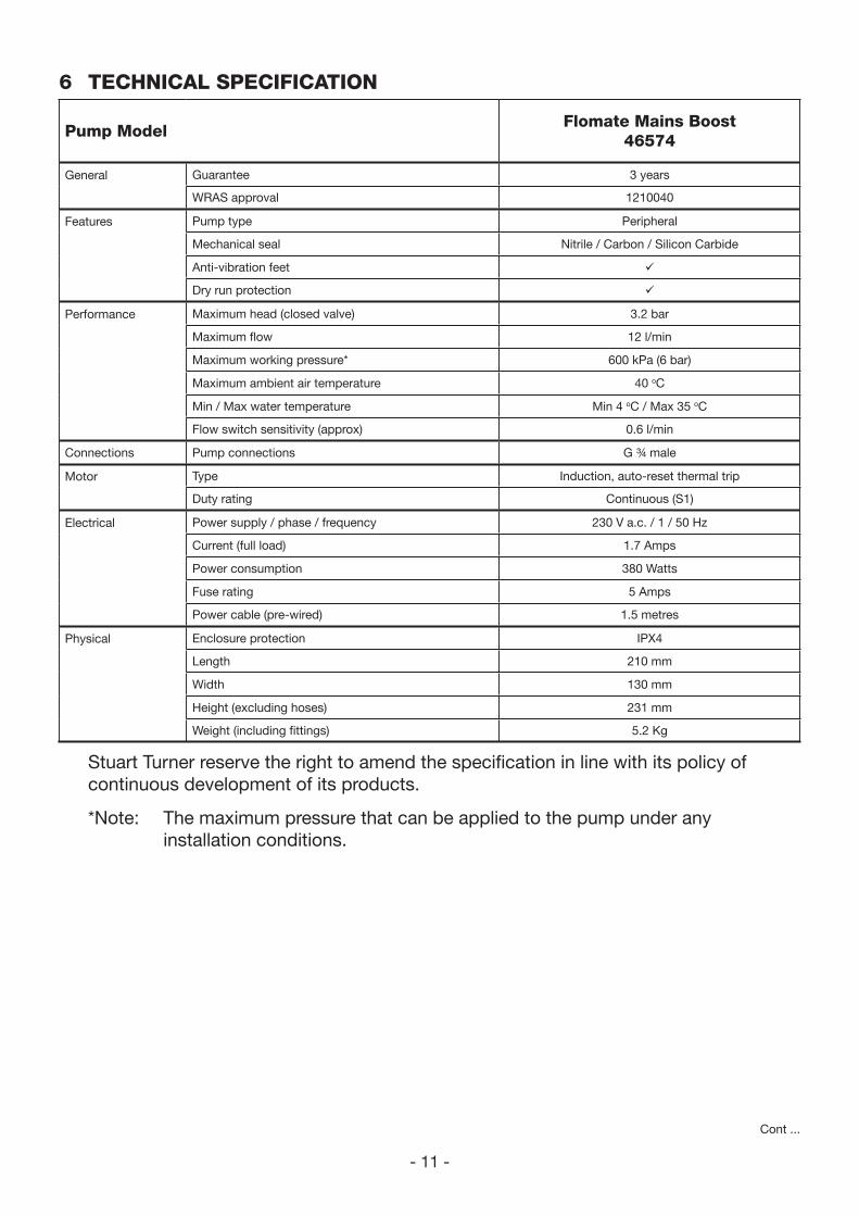
6 TECHNICAL SPECIFICATION
Stuart Turner reserve the right to amend the specification in line with its policy of
continuous development of its products.
*Note: The maximum pressure that can be applied to the pump under any
installation conditions.
Pump ModelFlomate Mains Boost
46574
General Guarantee 3 years
WRAS approval 1210040
Features Pump type Peripheral
Mechanical seal Nitrile / Carbon / Silicon Carbide
Anti-vibration feet
Dry run protection
Performance Maximum head (closed valve) 3.2 bar
Maximum flow 12 l/min
Maximum working pressure* 600 kPa (6 bar)
Maximum ambient air temperature 40 oC
Min / Max water temperature Min 4 oC / Max 35 oC
Flow switch sensitivity (approx) 0.6 l/min
Connections Pump connections G ¾ male
Motor Type Induction, auto-reset thermal trip
Duty rating Continuous (S1)
Electrical Power supply / phase / frequency 230 V a.c. / 1 / 50 Hz
Current (full load) 1.7 Amps
Power consumption 380 Watts
Fuse rating 5 Amps
Power cable (pre-wired) 1.5 metres
Physical Enclosure protection IPX4
Length 210 mm
Width 130 mm
Height (excluding hoses) 231 mm
Weight (including fittings) 5.2 Kg

- 12 -
Cont ...
7 TROUBLE SHOOTING GUIDE
Symptoms Probable Cause Recommended Action
Pump will not start. No water. Check required flow of liquid is available to the fittings of
approx. 0.6 l/min.
Water supply. Check water supply from mains and all stopcocks are open.
Electrical supply. Check wiring connections.
If flow exists inline with requirements - check that all electric
switches are on.
Is the correct fuse fitted?
Check circuit breaker is set.
Faulty reed switch/PCB Refer to circuit test as detailed in Fig. 5.
Internal motor thermotrip
activated.
Wait for thermotrip to auto reset and check that duty point
and run time is within specification (see Technical Section).
Pump starts when outlets are
off.
or
Pump cycles (hunts) on/off
frequently.
Leak in system Check tap washers, w/c valve washers, pipe joints.
Pump runs on when all terminal
outlets are closed.
Leak in system. Check tap washers, w/c valve washers, pipe joints.
Reed clamp out of position. Ensure reed clamp is fitted correctly in location groove
(Fig. 5).
Jammed flow switch. Remove flow switch reed clamp whilst pump is running. If
pump stops proceed to isolate the pump electrically and
hydraulically and remove brass housing that contains float.
Check for free movement.
Faulty reed switch or P.C.B. Remove flow switch reed clamp whilst pump is running.
If pump continues to run, this indicates a closed circuit in
either the flow switch reed or P.C.B. in the terminal box, these
should be checked electrically.
- 13 -
Cont ...
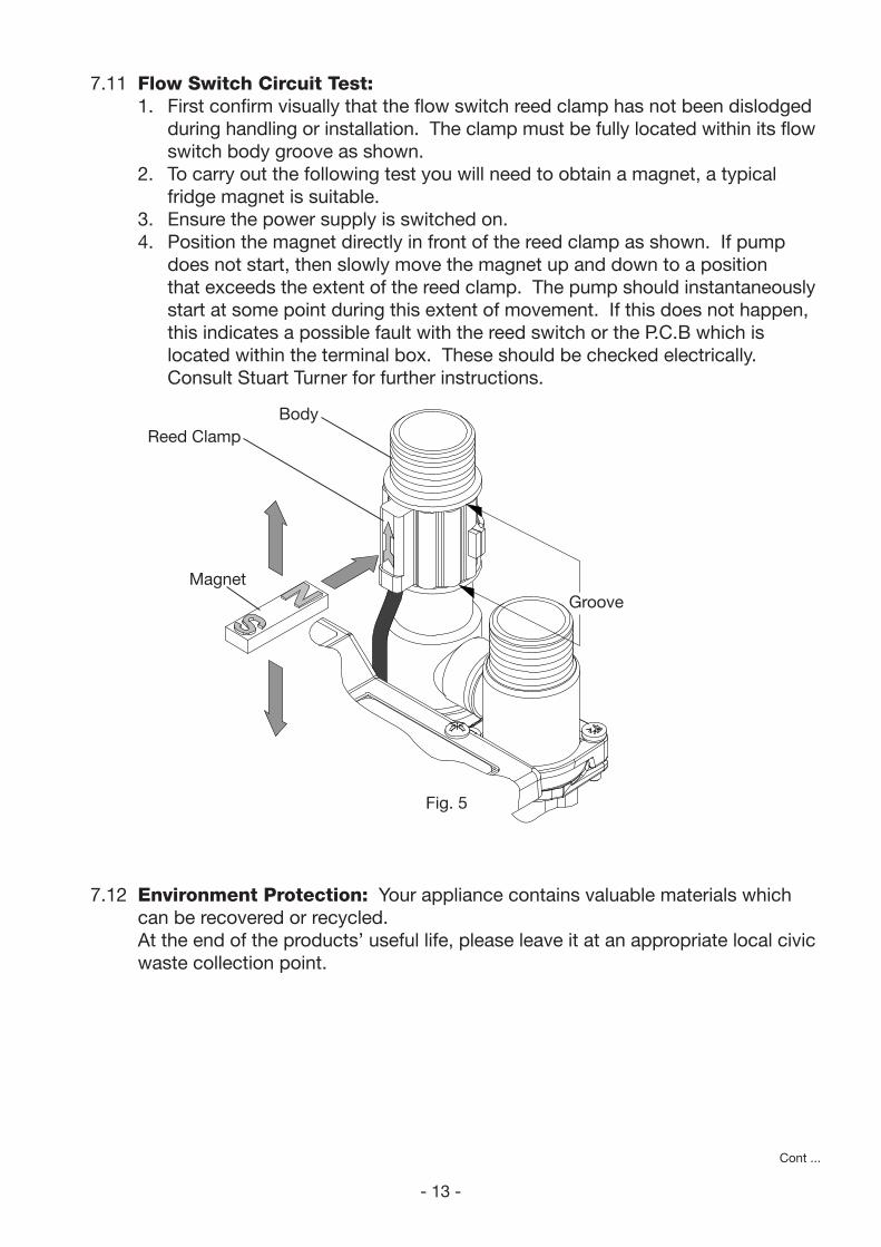
7.11 Flow Switch Circuit Test:
1. First confirm visually that the flow switch reed clamp has not been dislodged
during handling or installation. The clamp must be fully located within its flow
switch body groove as shown.
2. To carry out the following test you will need to obtain a magnet, a typical
fridge magnet is suitable.
3. Ensure the power supply is switched on.
4. Position the magnet directly in front of the reed clamp as shown. If pump
does not start, then slowly move the magnet up and down to a position
that exceeds the extent of the reed clamp. The pump should instantaneously
start at some point during this extent of movement. If this does not happen,
this indicates a possible fault with the reed switch or the P.C.B which is
located within the terminal box. These should be checked electrically.
Consult Stuart Turner for further instructions.
7.12 Environment Protection: Your appliance contains valuable materials which
can be recovered or recycled.
At the end of the products’ useful life, please leave it at an appropriate local civic
waste collection point.
Fig. 5
Groove
Body
Reed Clamp
Magnet
- 14 -
Cont ...
8 THE FLOMATE GUARANTEE
Congratulations on purchasing a Stuart Turner pump.
We are confident this pump will provide many years of trouble free service as all our
products are manufactured to the very highest standard.
The Flomate Pump is guaranteed to be free from defects in materials or workmanship
for 3 years from the date of purchase.
Within the guarantee period we will repair, free of charge, any defects in the pump
resulting from faults in material or workmanship, repairing or exchanging the whole
unit as we may reasonably decide.
Not covered by this guarantee: Damage arising from incorrect installation, improper
use, unauthorised repair, normal wear and tear and defects which have a negligible
effect on the value or operation of the pump.
Reasonable evidence must be supplied that the product has been purchased within
the guarantee term prior to the date of claim (such as proof of purchase or the pump
serial number).
This guarantee is in addition to your statutory rights as a consumer. If you are in any
doubt as to these rights, please contact your local Trading Standards Department.
In the event of a claim isolate the unit and then please telephone ‘PumpAssist’.
+44 (0) 844 98 000 97
Proof of purchase should accompany the returned unit to avoid delay in investigation
and dealing with your claim.
You should obtain appropriate insurance cover for any loss or damage which is not
covered by Stuart Turner Ltd in this provision.
Please record here for your records.
TYPE NO. SERIAL NO. DATE PURCHASED

- 15 -
Installers – Register with Stuart Turner and move up to Approved
Installer status
We receive thousands of enquiries every month from people seeking a Stuart
Turner installer and by registering your details with us, we can offer consumers the
opportunity to quickly locate an installer in their area.
Registration is free - simply click on the ‘register as an installer’ link
on our homepage at www.stuart-turner.co.uk and complete a short
form which will enable visitors to find your contact details on our web
site ‘installer finder’. Alternatively use your smartphone to scan this QR
code and go straight to the form.
We’ll do the rest!
In addition we will ensure you receive advance notice on all new product launches
and access to any special offers or promotions.
Following initial registration, Stuart Turner offers a professional training programme,
enabling you to achieve Approved Installer status and opening the door to a range of
additional benefits.
Contact [email protected] for further details.
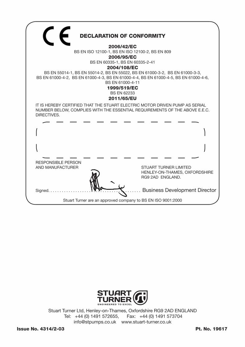
DECLARATION OF CONFORMITY
2006/42/ECBS EN ISO 12100-1, BS EN ISO 12100-2, BS EN 809
2006/95/ECBS EN 60335-1, BS EN 60335-2-41
2004/108/ECBS EN 55014-1, BS EN 55014-2, BS EN 55022, BS EN 61000-3-2, BS EN 61000-3-3,
BS EN 61000-4-2, BS EN 61000-4-3, BS EN 61000-4-4, BS EN 61000-4-5, BS EN 61000-4-6,
BS EN 61000-4-11
1999/519/ECBS EN 62233
2011/65/EU
IT IS HEREBY CERTIFIED THAT THE STUART ELECTRIC MOTOR DRIVEN PUMP AS SERIAL
NUMBER BELOW, COMPLIES WITH THE ESSENTIAL REQUIREMENTS OF THE ABOVE E.E.C.
DIRECTIVES.
RESPONSIBLE PERSON
AND MANUFACTURER STUART TURNER LIMITED
HENLEY-ON-THAMES, OXFORDSHIRE
RG9 2AD ENGLAND.
Signed . . . . . . . . . . . . . . . . . . . . . . . . . . . . . . . . . . . . . . . . . Business Development Director
Stuart Turner are an approved company to BS EN ISO 9001:2000
Stuart Turner Ltd, Henley-on-Thames, Oxfordshire RG9 2AD ENGLAND
Tel: +44 (0) 1491 572655, Fax: +44 (0) 1491 573704
[email protected] www.stuart-turner.co.uk
Issue No. 4314/2-03 Pt. No. 19617