Embed Size (px)
Citation preview

800-456-7100 I www.paladinlcg.com 503 Gay Street, Delhi, IA 52223, United States of America
SERIALNUMBER:___________________ ManualNumber:76824 PartNumber:76824 MODELNUMBER:___________________ Rev.2:January28,2010
FLOATINGPINCARRIAGE72.00”-96.00”
OPERATOR’S&PARTSMANUAL
M-1260 1-26-10-2


M-1327 10-12-06
PREFACE....................................................................................................................................3SAFETY PRECAUTIONS ....................................................................................................... 4-7 SAFETY STATEMENTS .......................................................................................................................................4 GENERAL SAFETY PRECAUTIONS................................................................................................................4-6 EQUIPMENT SAFETY PRECAUTIONS ..............................................................................................................7INSTALLATION AND OPERATION ............................................................................................8 ATTACHING & DETACHING .................................................................................................................................8 OPERATING EQUIPMENT ...................................................................................................................................8STORAGE ...................................................................................................................................9 GENERAL INFORMATION ....................................................................................................................................9 PREPARATION FOR STORAGE ..........................................................................................................................9 REMOVING FROM STORAGE .............................................................................................................................9LIMITED WARRANTY ..............................................................................................................11PARTS 72” FLOATING PIN FORK CARRIAGE ASSEMBLY #16320 .........................................................................14-15 74” FLOATING PIN FORK CARRIAGE ASSEMBLY #11714 .........................................................................16-17 74” FLOATING PIN FORK CARRIAGE ASSEMBLY #12243 .........................................................................18-19 74” FLOATING PIN FORK CARRIAGE ASSEMBLY #12557 .........................................................................20-21 84” FLOATING PIN FORK CARRIAGE ASSEMBLY #12377 .........................................................................22-23 96” FLOATING PIN FORK CARRIAGE ASSEMBLY #12595 .........................................................................24-25
TABLE OF CONTENTS
76824 1

DESCRIPTION & MOUNT ASSEMBLY #
CATERPILLAR74” Floating Pin Fork Carriage - CAT IT/TH (Shown) 1171474” Floating Pin Fork Carriage - CAT BOOM MOUNT (Shown) 12243
JCB74” Floating Pin Fork Carriage - JCB 540 BOOM MOUNT (Shown) 1255784” Floating Pin Fork Carriage - JCB 411, 416, 426 WITH HT COUPLER (Shown) 1237796” Floating Pin Fork Carriage - JCB 532/550 BOOM MOUNT (Shown) 12595
MANITOU72” Floating Pin Fork Carriage - MANITOU 523/632/932 (Shown) 16320
NEW HOLLAND84” Floating Pin Fork Carriage - NH LW 130-170 WITH QUICK COUPLER (Shown) 12377
VOLVO84” Floating Pin Fork Carriage - VOLVO L70-L120 WITH QUICK COUPLER (Shown) 12377
FOREWORD
M-1328 1-28-10-2
Although Bradco has various fork carriages available in the 72” - 96” range, we are continually designing new sizes and mountings. If your combination is not listed, please contact the fac-tory. We have extensive mounting information available to generate the product you need.
Below is a listing of the fork carriages that are currently available. See the “Parts” section of this manual for the assemblies “Shown”.
2 76824

PREFACE
GENERAL COMMENTS Congratulations on the purchase of your new attachment! This product was carefully designed and manufactured to give you many years of dependable service. Only minor main-tenance, such as cleaning and lubricating, is required to keep it in top working condition. Be sure to observe all maintenance procedures and safety precautions in this manual and on any safety decals located on the product, and on any equipment on which the attachment is mount-ed. Also, check load charts before operating the attachment. This manual has been designed to help you do a better, safer job. Read this manual carefully and become familiar with its contents.
WARNING! Never let anyone operate this unit without reading the “Safety Precautions” and “Operating Instructions” sections of this manual.
Always choose hard, level ground to park the vehicle on, and set the brake so the unit cannot roll.
Unless noted otherwise, right and left sides are determined from the operator’s control position when facing the attachment.
NOTE: The illustrations and data used in this manual were current, according to the information available to us at the time of printing. However, we reserve the right to rede-sign and change the attachment as may be necessary, without notifi cation.
BEFORE OPERATION The primary responsibility for safety with this equipment falls to the operator. Make sure the equipment is operated only by trained individuals who have read and understand this manual. If there is any portion of this manual or function that you do not understand, contact your local authorized dealer or the manufacturer.
SAFETY ALERT SYMBOLThis is the “Safety Alert Symbol” used by this industry. This symbol is used to warn of possible injury. Be sure to read all warnings carefully. They are included for your safety and for the safety of others working with you.
SERVICE When servicing your product, remember to use only manufacturer replacement parts. Substitute parts may not meet the standards required for safe, dependable operation. To facilitate parts ordering, record the model and serial number of your unit in the space provided on the cover of this manual. This information may be obtained from the identifi cation plate located on the product. The parts department needs this information to ensure that you receive the correct parts for your specifi c model.
M-934 9-21-05-2
76824 3

M-806 7-28-05-2
SAFETY STATEMENTS
DANGER
GENERAL SAFETY PRECAUTIONS
WARNING! READ MANUAL PRIOR TO INSTALLATIONImproper installation, operation, or maintenance of this equipment could result in se-rious injury or death. Operators and maintenance personnel should read this manual, as well as all manuals related to this equipment and the prime mover thoroughly before beginning installation, operation, or maintenance. FOLLOW ALL SAFETY INSTRUCTIONS IN THIS MANUAL AND THE PRIME MOVER’S MANUAL(S).
READ AND UNDERSTAND ALL SAFETY STATEMENTSRead all safety decals and safety statements in all manuals prior to operating or working on this equipment. Know and obey all OSHA regulations, local laws, and other professional guidelines for your operation. Know and follow good work prac-tices when assembling, maintaining, repairing, mounting, removing, or operating this equipment.
KNOW YOUR EQUIPMENTKnow your equipment’s capabilities, dimensions, and operations before operating. Visually inspect your equipment before you start, and never operate equipment that is not in proper working order with all safety devices intact. Check all hardware to ensure it is tight. Make certain that all locking pins, latches, and connection devices are properly installed and secured. Remove and replace any damaged, fatigued, or excessively worn parts. Make certain all safety decals are in place and are legible. Keep decals clean, and replace them if they become worn or hard to read.
WARNING
CAUTION
THIS SIGNAL WORD IS USED WHERE SERIOUS INJURY OR DEATHWILL RESULT IF THE INSTRUCTIONS ARE NOT FOLLOWED PROPERLY.
THIS SIGNAL WORD IS USED WHERE SERIOUS INJURY OR DEATHCOULD RESULT IF THE INSTRUCTIONS ARE NOT FOLLOWED PROPERLY.
THIS SIGNAL WORD IS USED WHERE MINOR INJURY COULD RESULT IF THE INSTRUCTIONS ARE NOT FOLLOWED PROPERLY.
NOTICE INDICATES A PROPERTY DAMAGE MESSAGE. NOTICE
THIS SYMBOL BY ITSELF OR WITH A WARNING WORD THROUGHOUT THIS MAN-UAL IS USED TO CALL YOUR ATTENTION TO INSTRUCTIONS INVOLVING YOUR PERSONAL SAFETY OR THE SAFETY OF OTHERS. FAILURE TO FOLLOW THESE INSTRUCTIONS CAN RESULT IN INJURY OR DEATH.
4 76824

GENERAL SAFETY PRECAUTIONS
WARNING! PROTECT AGAINST FLYING DEBRISAlways wear proper safety glasses, goggles, or a face shield when driving pins in or out, or when any operation causes dust, fl ying debris, or any other hazardous mate-rial.
WARNING! LOWER OR SUPPORT RAISED EQUIPMENTDo not work under raised booms without supporting them. Do not use support mate-rial made of concrete blocks, logs, buckets, barrels, or any other material that could suddenly collapse or shift positions. Make sure support material is solid, not de-cayed, warped, twisted, or tapered. Lower booms to ground level or on blocks. Lower booms and attachments to the ground before leaving the cab or operator’s station.
WARNING! USE CARE WITH HYDRAULIC FLUID PRESSUREHydraulic fl uid under pressure can penetrate the skin and cause serious injury or death. Hydraulic leaks under pressure may not be visible. Before connecting or dis-connecting hydraulic hoses, read your prime mover’s operator’s manual for detailed instructions on connecting and disconnecting hydraulic hoses or fi ttings.
• Keep unprotected body parts, such as face, eyes, and arms as far away as possible from a suspected leak. Flesh injected with hydraulic fl uid may develop gangrene or other permanent disabilities.
• If injured by injected fl uid, see a doctor at once. If your doctor is not familiar with this type of injury, ask him to research it immediately to determine proper treat-ment.
• Wear safety glasses, protective clothing, and use a piece of cardboard or wood when searching for hydraulic leaks. DO NOT USE YOUR HANDS! SEE ILLUS-TRATION.
CARDBOARD
HYDRAULIC HOSEOR FITTING
MAGNIFYING GLASS
M-807 7-28-05-2
76824 5

GENERAL SAFETY PRECAUTIONS
M-808 7-28-05-2
WARNING! DO NOT MODIFY MACHINE OR ATTACHMENTSModifi cations may weaken the integrity of the attachment and may impair the func-tion, safety, life, and performance of the attachment. When making repairs, use only the manufacturer’s genuine parts, following authorized instructions. Other parts may be substandard in fi t and quality. Never modify any ROPS (Roll Over Protection Structure) or FOPS (Falling Object Protective Structure) equipment or device. Any modifi cations must be authorized in writing by the manufacturer.
WARNING! SAFELY MAINTAIN AND REPAIR EQUIPMENT• Do not wear loose clothing or any accessories that can catch in moving parts. If
you have long hair, cover or secure it so that it does not become entangled in the equipment.
• Work on a level surface in a well-lit area.• Use properly grounded electrical outlets and tools.• Use the correct tools for the job at hand. Make sure they are in good condition for
the task required.• Wear the protective equipment specifi ed by the tool manufacturer.
SAFELY OPERATE EQUIPMENTDo not operate equipment until you are completely trained by a qualifi ed operator in how to use the controls, know its capabilities, dimensions, and all safety require-ments. See your machine’s manual for these instructions.• Keep all step plates, grab bars, pedals, and controls free of dirt, grease, debris,
and oil.• Never allow anyone to be around the equipment when it is operating.• Do not allow riders on the attachment or the prime mover.• Do not operate the equipment from anywhere other than the correct operator’s
position. • Never leave equipment unattended with the engine running, or with this attach-
ment in a raised position.• Do not alter or remove any safety feature from the prime mover or this attach-
ment.• Know your work site safety rules as well as traffi c rules and fl ow. When in doubt
on any safety issue, contact your supervisor or safety coordinator for an explana-tion.
6 76824

EQUIPMENT SAFETY PRECAUTIONS
WARNING! KNOW WHERE UTILITIES AREObserve overhead electrical and other utility lines. Be sure equipment will clear them. When digging, call your local utilities for location of buried utility lines, gas, water, and sewer, as well as any other hazard you may encounter.
OPERATING THE PRIME MOVERAvoid steep hillside operation, which could cause the prime mover to overturn. Con-sult your machine operator’s and safety manuals for maximum incline allowable.
When operating on a slope, keep the load low, and proceed with extreme caution. Do not drive ACROSS a steep slope - drive straight up and down. With LOADED forks - drive with the forks and load facing uphill. With EMPTY forks - drive with the forks facing downhill.
WORKING WITH THE ATTACHMENT• Never use the attachment for a work platform or personnel carrier.• Specifi ed lift capacities must not be exceeded, otherwise machine stability will
not be suffi cient. Always observe lift capacity limits listed in machine specifi ca-tions or on load charts furnished with the prime mover.
• An operator must not use drugs or alcohol, which can change his or her alertness or coordination. An operator taking prescription or over-the-counter drugs should seek medical advice on whether or not he or she can safely operate equipment.
• Always check locking pins before operating any attachment. • Never lift, move, or swing loaded forks over anyone.• Always space the forks correctly for the load. Loads can fall off incorrectly
spaced forks. Make sure the forks are completely under the load before lifting.• Never stack loads on uneven ground. Loads stacked on uneven ground can
topple.• Never lift a load with one fork. A load lifted with one fork can slip off and cause
injury.• Secure loads properly. Unsecured loads can fall unexpectedly.• Do not handle round bales with fork lift tines.• Don’t obstruct your vision when traveling or working. Carry the forks low for maxi-
mum stability and visibility.
MAINTAINING THE ATTACHMENT• Never perform any work on the equipment unless you are authorized and quali-
fi ed to do so. Always read the operator’s and service manual(s) before any repair is made. After completing maintenance or repair, check for correct functioning of the attachment. If not functioning properly, always attach a “DO NOT OPERATE” tag to the machine until all problems are corrected.
• Worn, damaged, or illegible safety decals must be replaced. New safety decals can be ordered from the manufacturer.
M-1014 8-23-05
76824 7

INSTALLATION AND OPERATION
M-1321 4-13-06
ATTACHING AND DETACHING EQUIPMENTPlease see your vehicle operator’s manual for instructions on attaching and detaching your equipment.
WARNING! To prevent serious personal injury or death, only attach equipment that isdesigned for your prime mover.
Specifi ed lift capacities must not be exceeded, otherwise machine stability will not be suffi cient. Always observe lift capacity limits listed in machine specifi ca-tions.
OPERATING EQUIPMENTRead all Safety Precautions before operating your new attachment.
For personal safety, lower the attachment to the ground, set the parking brake, shut off engine, and remove key before getting off of your prime mover.
8 76824

STORAGE
GENERAL INFORMATION
The following storage procedure will help you to keep your attachment in top condition. It will also help you get off to a good start the next time your equipment is needed. We therefore strongly recommend that you take the extra time to follow these procedures whenever your attachment will not be used for an extended period of time.
PREPARATION FOR STORAGE
1. Clean the attachment thoroughly, removing all mud, dirt, and grease.
2. Inspect for visible signs of wear, breakage, or damage. Order any parts required, and make the necessary repairs, to avoid delays when starting next season.
3. Tighten all loose nuts and capscrews.
4. Touch up all unpainted and exposed areas with paint, to prevent rust.
5. Replace decals, if damaged or in unreadable condition.
6. Store the attachment in a dry and protected place, with a cover, if possible. Leaving the attachment outside will materially shorten its life.
REMOVING FROM STORAGE
1. Remove all protective coverings.
M-1192 2-9-06
76824 9

THIS PAGEIS INTENTIONALLY
BLANK
10 76824

Limited WarrantyExcept for the Excluded Products as described below, all new products are warranted to be free from defects in material and/or workmanship during the Warranty Period, in accordance with and subject to the terms and conditions of this Limited Warranty.
1. Excluded Products. The following products are excluded from this Limited Warranty:
(a) Any cable, part that engages with the ground (i.e. sprockets), digging chain, bearing, teeth, tamping and/or demolition head, blade cutting edge, pilot bit, auger teeth and broom brush that either constitutes or is part of a product.
(b) Any product, merchandise or component that, in the opinion of Paladin Light Construction1, has been (i) misused; (ii) modified in any unauthorized manner; (iii) altered; (iv) damaged; (v) involved in an accident; or (vi) repaired using parts not obtained through Paladin Light Construction.
2. Warranty Period. The Limited Warranty is provided only to those defects that occur during the Warranty Period, which is the period that begins on the first to occur of: (i) the date of initial purchase by an end-user, (ii) the date the product is first leased or rented, or (iii) the date that is six (6) months after the date of shipment by Paladin Light Construction as evidenced by the invoiced shipment date (the “Commencement Date”) and ends on the date that is twelve (12) months after the Commencement Date.
3. Terms and Conditions of Limited Warranty. The following terms and conditions apply to the Limited Warranty hereby provided:
(a) Option to Repair or Replace. Paladin Light Construction shall have the option to repair or replace the product.
(b) Timely Repair and Notice. In order to obtain the Limited Warranty, (i) the product must be repaired within thirty (30) days from the date of failure, and (ii) a claim under the warranty must be submitted to Paladin Light Construction in writing within thirty (30) days from the date of repair.
(c) Return of Defective Part or Product. If requested by Paladin Light Construction, the alleged defective part or product shall be shipped to Paladin Light Construction at its manufacturing facility or other location specified by Paladin Light Construction, with freight PRE-PAID by the claimant, to allow Paladin Light Construction to inspect the part or product.
Claims that fail to comply with any of the above terms and conditions shall be denied.
LIMITATIONS AND EXCLUSIONS.
THIS LIMITED WARRANTY IS IN LIEU OF ALL OTHER WARRANTIES, EXPRESS OR IMPLIED, INCLUDING WITHOUT LIMITATION THE WARRANTIES OF MERCHANTABILITY, FITNESS FOR A PARTICULAR PURPOSE AND ANY WARRANTY BASED ON A COURSE OF DEALING OR USAGE OF TRADE.
IN NO EVENT SHALL PALADIN LIGHT CONSTRUCTION BE LIABLE FOR CONSEQUENTIAL OR SPECIAL DAMAGES.
IN NO EVENT SHALL PALADIN LIGHT CONSTRUCTION BE LIABLE FOR ANY LOSS OR CLAIM IN AN AMOUNT IN EXCESS OF THE PURCHASE PRICE, OR, AT THE OPTION OF PALADIN LIGHT CONSTRUCTION, THE REPAIR OR REPLACEMENT, OF THE PARTICULAR PRODUCT ON WHICH ANY CLAIM OF LOSS OR DAMAGE IS BASED. THIS LIMITATION OF LIABILITY APPLIES IRRESPECTIVE OF WHETHER THE CLAIM IS BASED ON BREACH OF CONTRACT, BREACH OF WARRANTY, NEGLIGENCE OR OTHER CAUSE AND WHETHER THE ALLEGED DEFECT IS DISCOVERABLE OR LATENT.
1Attachment Technologies Inc., a subsidiary of Paladin Brands Holding, Inc. (PBHI) is referred to herein as Paladin Light Construction.
February 10, 201076824 11

THIS PAGEIS INTENTIONALLY
BLANK
12 76824

M-1127 1-26-10-3
PARTS
The following section contains detailed diagrams and parts lists which include your attachment. Please use these diagrams and parts lists to locate replacement parts, prior to contacting the parts department.
When servicing your attachment, remember to use only original manufacturer replace-ment parts. Substitute parts may not meet the standards required for safe, dependable opera-tion.
To facilitate parts ordering, have the model and serial number of your product ready, to ensure that you receive the correct parts for your specific attachment.
The model and serial number for your attachment should be recorded in the space provided on the cover of this manual. This information may be obtained from the serial number identification plate located on your attachment. See the parts diagram for your attachment for the location.
NOTE: Most daily and emergency orders received by 2:00 P.M. will be shipped the same day received, with “Emergency-Machine-Down” orders receiving first priority.
PARTS DEPARTMENT(734) 996-9116(800) 456-7100
We Encourage Fax Orders(734) 996-9014
76824 13

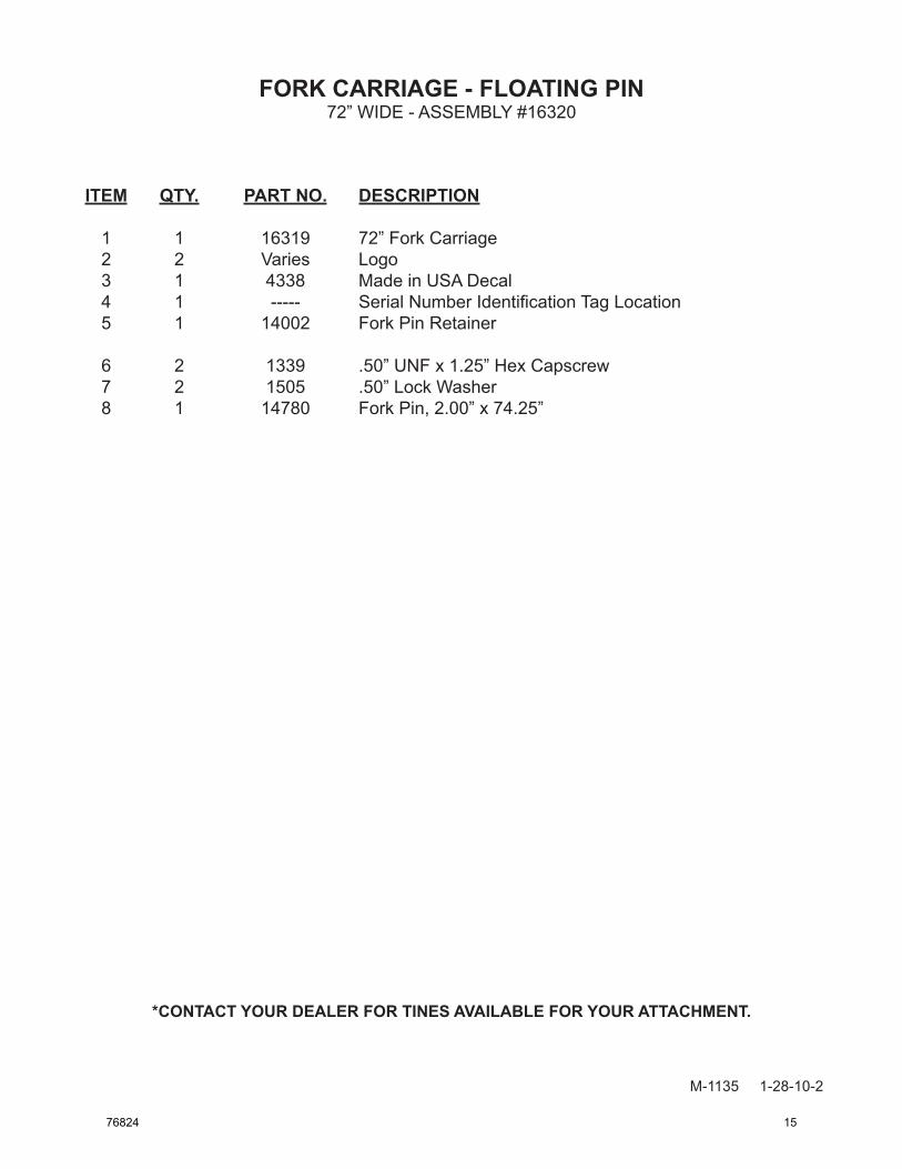
FORK CARRIAGE - FLOATING PIN 72” WIDE - ASSEMBLY #16320
M-1134 1-28-10-2
3MADE IN U.S.A.
1
2
4
6
5
7
FORK
8
FORK
23
14 76824
FORK CARRIAGE - FLOATING PIN
M-1135 1-28-10-2
ITEM QTY. PART NO. DESCRIPTION
1 1 16319 72” Fork Carriage 2 2 Varies Logo 3 1 4338 Made in USA Decal 4 1 ----- Serial Number Identification Tag Location 5 1 14002 Fork Pin Retainer
6 2 1339 .50” UNF x 1.25” Hex Capscrew 7 2 1505 .50” Lock Washer 8 1 14780 Fork Pin, 2.00” x 74.25”
72” WIDE - ASSEMBLY #16320
*CONTACT YOUR DEALER FOR TINES AVAILABLE FOR YOUR ATTACHMENT.
76824 15

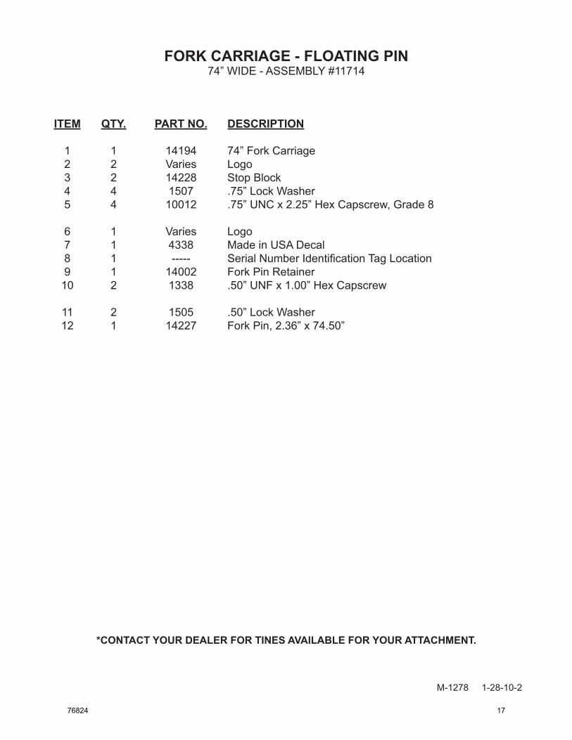
FORK CARRIAGE - FLOATING PIN 74” WIDE - ASSEMBLY #11714
M-1277 1-28-10-2
7MADE IN U.S.A.
1
2
76 10
9
11
FORK
12
FORK
8
2
3
4 5
16 76824
FORK CARRIAGE - FLOATING PIN
M-1278 1-28-10-2
ITEM QTY. PART NO. DESCRIPTION
1 1 14194 74” Fork Carriage 2 2 Varies Logo 3 2 14228 Stop Block 4 4 1507 .75” Lock Washer 5 4 10012 .75” UNC x 2.25” Hex Capscrew, Grade 8
6 1 Varies Logo 7 1 4338 Made in USA Decal 8 1 ----- Serial Number Identification Tag Location 9 1 14002 Fork Pin Retainer 10 2 1338 .50” UNF x 1.00” Hex Capscrew
11 2 1505 .50” Lock Washer 12 1 14227 Fork Pin, 2.36” x 74.50”
74” WIDE - ASSEMBLY #11714
*CONTACT YOUR DEALER FOR TINES AVAILABLE FOR YOUR ATTACHMENT.
76824 17

FORK CARRIAGE - FLOATING PIN 74” WIDE - ASSEMBLY #12243
M-1273 1-28-10-2
3MADE IN U.S.A.
1
5
32
8
7
9
FORK
6
FORK
4
5
18 76824

FORK CARRIAGE - FLOATING PIN
M-1274 1-28-10-2
ITEM QTY. PART NO. DESCRIPTION
1 1 14104 74” Fork Carriage 2 1 Varies Logo 3 1 4338 Made in USA Decal 4 1 ----- Serial Number Identification Tag Location 5 2 Varies Logo
6 1 14227 Fork Pin, 2.36” x 74.50” 7 1 14002 Fork Pin Retainer 8 2 1505 .50” Lock Washer 9 2 1338 .50” UNF x 1.00” Hex Capscrew
74” WIDE - ASSEMBLY #12243
*CONTACT YOUR DEALER FOR TINES AVAILABLE FOR YOUR ATTACHMENT.
76824 19

FORK CARRIAGE - FLOATING PIN74” WIDE - ASSEMBLY #12557
M-1324 1-28-10-2
2
MADE IN U.S.A.
23
1
5
46
78
910
10
1111
11
1212
12
13
FORK
FORK
14
15
1617
18
1920
22
21
20 76824

FORK CARRIAGE - FLOATING PIN74” WIDE - ASSEMBLY #12557
M-1325 10-12-06
ITEM QTY. PART NO. DESCRIPTION
1 1 17501 74" Fork Carriage 2 1 4338 Made in USA Decal 3 1 ----- Serial Number Identifi cation Tag Location 4 1 31795 Spring 5 2 31794 Bushing
6 1 31793 Handle 7 1 1614 .16" x 2.00" Cotter Pin 8 1 11740 Linkage 9 2 31798 Attaching Strap 10 2 31801 Pin, .63" x 10.00"
11 4 1069 .44" UNC x 1.75" Hex Capscrew 12 4 1745 .44" UNC Nylock Hex Nut 13 1 16913 Fork Pin, 2.25" x 79.00" 14 2 31776 Fork Pin Locking Handle 15 2 31996 Drilled Pin, 1.00" x 5.50"
16 2 1258 .25" UNF x 2.25" Hex Capscrew 17 2 1501 .25" Lock Washer 18 2 1474 .25" UNF Hex Nut 19 1 100876 Mounting Pin, 2.00" x 21.14" 20 1 1056 .38" UNC x 4.50" Hex Capscrew
21 1 1542 .50" UNC Nylock Hex Nut 22 2 82026 Hitch Pin, .75" x 5.25"
*CONTACT YOUR DEALER FOR TINES AVAILABLE FOR YOUR ATTACHMENT.
76824 21

FORK CARRIAGE - FLOATING PIN 84” WIDE - ASSEMBLY #12377
M-1275 1-28-10-2
3MADE IN U.S.A.
1
5
3
FORK
6
FORK
4
25
7
8
10
9
22 76824

FORK CARRIAGE - FLOATING PIN
M-1276 1-28-10-2
ITEM QTY. PART NO. DESCRIPTION
1 1 15743 84” Fork Carriage 2 1 Varies Logo 3 1 4338 Made in USA Decal 4 1 ----- Serial Number Identification Tag Location 5 2 Varies Logo
6 1 15745 Fork Pin, 2.25” x 87.38” 7 1 14002 Fork Pin Retainer 8 2 1516 .50” Flat Washer 9 2 1505 .50” Lock Washer 10 2 1339 .50” UNF x 1.25” Hex Capscrew
84” WIDE - ASSEMBLY #12377
*CONTACT YOUR DEALER FOR TINES AVAILABLE FOR YOUR ATTACHMENT.
76824 23
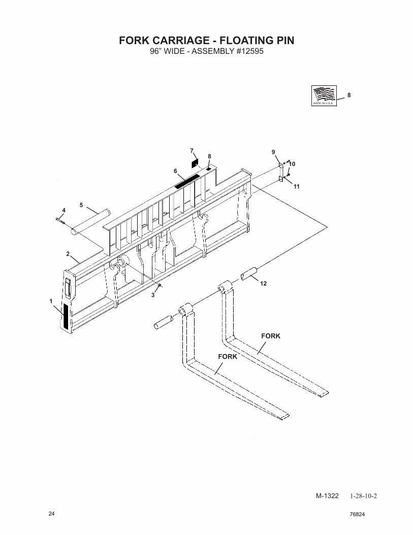
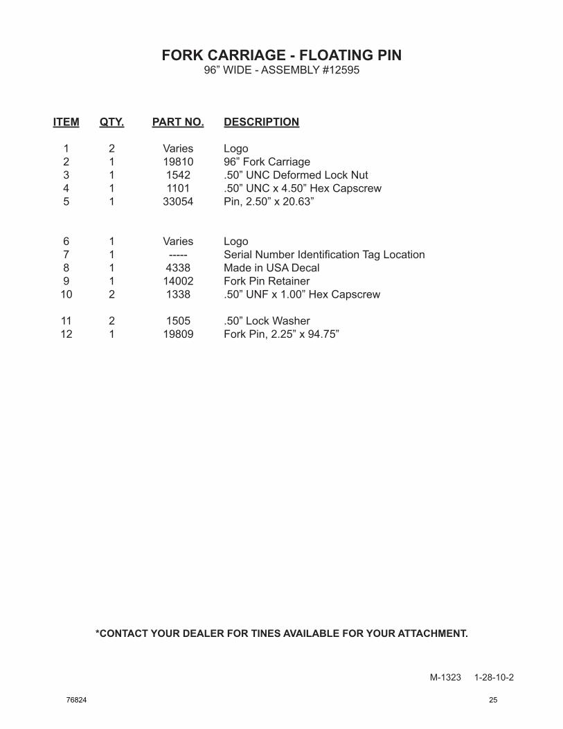
FORK CARRIAGE - FLOATING PIN 96” WIDE - ASSEMBLY #12595
M-1322 1-28-10-2
8MADE IN U.S.A.
1
6
2
11
10
12
FORK
9
FORK
78
54
3
24 76824
FORK CARRIAGE - FLOATING PIN
M-1323 1-28-10-2
ITEM QTY. PART NO. DESCRIPTION
1 2 Varies Logo 2 1 19810 96” Fork Carriage 3 1 1542 .50” UNC Deformed Lock Nut 4 1 1101 .50” UNC x 4.50” Hex Capscrew 5 1 33054 Pin, 2.50” x 20.63”
6 1 Varies Logo 7 1 ----- Serial Number Identification Tag Location 8 1 4338 Made in USA Decal 9 1 14002 Fork Pin Retainer 10 2 1338 .50” UNF x 1.00” Hex Capscrew
11 2 1505 .50” Lock Washer 12 1 19809 Fork Pin, 2.25” x 94.75”
96” WIDE - ASSEMBLY #12595
*CONTACT YOUR DEALER FOR TINES AVAILABLE FOR YOUR ATTACHMENT.
76824 25

M-1360 1-26-10-2
503 Gay StreetDelhi, IA 52223
(563) 922-2981(800) 456-7100
www.paladinlcg.com
26 76824