Embed Size (px)
DESCRIPTION
Fliteveyor incline
Citation preview

MP - 1.5M - 5/13
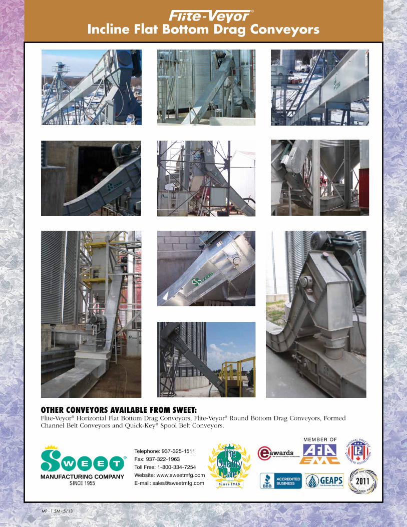
Other cOnveyOrs available frOm sweet: Flite-Veyor® Horizontal Flat Bottom Drag Conveyors, Flite-Veyor® Round Bottom Drag Conveyors, Formed Channel Belt Conveyors and Quick-Key® Spool Belt Conveyors.
MANUFACTURING COMPANYSINCE 1955
Incline Flat Bottom Drag Conveyors Incline Flat Bottom Drag Conveyors • 17 Series
MEMBER OF
Telephone: 937-325-1511
Fax: 937-322-1963
Toll Free: 1-800-334-7254
Website: www.sweetmfg.com
E-mail: [email protected]
Hecho en USA
Made in the USA
Hecho en USA
Made in the USA

incline caPacity chartMODEL
1017 1417 1817 2017 2417 FPM MPS FPM MPS FPM MPS FPM MPS FPM MPS
2,000 (50) 2280 0.40
3,000 (76) 32117 0.59 84 0.43
4,000 (102) 43156 0.79 112 0.57 87 0.44
5,000 (127) 139 0.71 108 0.55 98 0.50
6,000 (152) 167 0.85 130 0.66 117 0.59 100 0.51
7,000 (178) 152 0.77 137 0.70 116 0.59
8,000 (203) 173 0.88 156 0.79 133 0.68
9,000 (228) 175 0.89 149 0.76
10,000 (253) 166 0.84
DimensiOns MODEL
1017 1417 1817 2017 2417
A 10" 14" 18" 20" 24" B (15º) 24" 19" 19" 19" 20" B (30º) 29" 22" 20" 20" 21" B (45º) 30" 29" 27" 27" 27"
15º 30º 45º 15º 30º 45º C 32" 40.5" 44" 40" 46.5" 50" D 3" 12.5" 27" 34" 28.5" 21.5" E 27" 31" 25.5" 27" 31" 25.5" F 24" 46" 65" 24" 46" 65" G (Per 10') 31" 60" 85" 31" 60" 85" H (Per 10') 116" 104" 85" 116" 104" 85"
TROUGH CROSS SECTION
1017 1417 1817 2017 2417
I 13.5" 17.5" 21.5" 23.5" 27.5" J 10" 14" 18" 20" 24" K 17" 17" 17" 17" 17" L 8.5" 8.5" 8.5" 8.5" 8.5"
I
J
K
Note: Dimensions (to the nearest 1/2 inch) are for reference only and may be subject to change.
DimensiOns
Model Number M N M N O P Q R S
1017 18" 21.5" 26" 29.5" 22" 25.5" 48" 22" 10"
1417 18" 21.5" 26" 29.5" 26" 29.5" 52" 22" 14"
1817 18" 21.5" 26" 29.5" 30" 33.5" 56" 22" 18"
2017 18" 21.5" 26" 29.5" 32" 35.5" 68" 27" 20"
2417 18" 21.5" 26" 29.5" 42" 45.5" 75" 26" 24"
OP
OPtiOns
eXtra stanDarD inlet Standard angle flange inlets are recommended for use on applications where material flow is controlled before entering the conveyor.
byPass inlet Bypass inlet funnels grain directly into the lower portion of the trough. This method of feeding provides automatic flow control into the conveyor, preventing pressure buildup on the chain. The bypass inlet is recommended where flow control is not provided before entering the conveyor.
DUmP hOPPer Dump hoppers replace a section of the trough for use in pit applications. The hopper diverts material around the return chain and provides an even flow into the lower portion of the Flite-Veyor®. This prevents pressure buildup on the chain and reduces horsepower requirements. The dump hopper is available in different lengths.
intermeDiate DischarGe Intermediate discharges have a 36" (914.4 mm) opening. Steel cross members support the chain over the opening while allowing 100% of the material to discharge. The intermediate discharge has a side opening or inline slide gate with manual, rack and pinion, electric, or pneumatic controls available. An optional discharge transition tapers the 36" (914.4 mm) long opening down to an opening that is 18" (457.2 mm) long.
BYPASS INLETN
M
DUMP HOPPER ASSEMBLY
120"
Q
R
2"
S
ByPASS INLET Standard Extended
DUMP HOPPER
Other lengths available upon request. Contact sales for price and availability.Note: Dimensions (to the nearest 1/2 inch) are for reference only and may be subject to change.
GaUGes & sPecificatiOnsHEAD 3/16 ga. TAIL 10 ga. TROUGH 10 ga. COVER 14 ga. CHAINS D88K, D88C, D308C
2"
Our MISSIOn: To provide innovative quality solutions that create an extraordinary customer experience.
Abrasion resistant liners available for trough sides and bottoms. Gauge options include 10 ga., 3/16" and 1/4".
TROUGH CROSS SECTION
17"
INTERMEDIATE DISCHARGE GATE WITH OPTIONAL TRANSITION
HINGED PRESSURE RELIEF DOOR
the Difference The Flite-Veyor® line of incline flat bottom drag conveyors offers five models with capacities ranging up to 10,000 bph/253 mtph. We offer both straight and curved inclines available at 15, 30 or 45 degree angles. Our range and flexibility can help meet the unique demands of your application – size, speed, throughput and overall processing capacity. The Flite-Veyor® line features:
• Completegalvanizedconstruction,includinghot-dipgalvanizingofallstructuralsteel.
•Head assembly pillow block bearing bases mounted in the optimum position, perpendicular to the load.
•Design specifications listed with a standard Class II drive package.
•Zinc plated tie rods, nickel plated bushings and hot-dip galvanized motor mounts standard with all drive packages.
Bushels/Hour(Metric Tons/
Hour)
FPM= Feet per minute MPS= Meters per second
L
Standard Head Extended Head
REMOVABLE SHAFT ASSEMBLY
OPTIONAL DISCHARGE TRANSITION
UHMW PLASTIC FLIGHTS
LOAD RATED CHAIN
REQUIRED LENGTH
10 GA. GALV. TROUGH
FLAME CUT BUSHABLE SPROCKETS
STANDARD INLET ASSEMBLED AT INSTALLATION
INCLINE REQUIRED LENGTH
HORIZONTAL REQUIRED LENGTH
5' & 10'STANDARD
SPHERICAL ROLLER BEARINGS
HD BALL BEARING TAKE-UPS
STRAIGHT INCLINE
CURVED INCLINE
UHMW CURVED CHAIN GUIDE
MP - 1.5M - 5/13
Other cOnveyOrs available frOm sweet: Flite-Veyor® Horizontal Flat Bottom Drag Conveyors, Flite-Veyor® Round Bottom Drag Conveyors, Formed Channel Belt Conveyors and Quick-Key® Spool Belt Conveyors.
MANUFACTURING COMPANYSINCE 1955
Incline Flat Bottom Drag Conveyors Incline Flat Bottom Drag Conveyors • 17 Series
MEMBER OF
Telephone: 937-325-1511
Fax: 937-322-1963
Toll Free: 1-800-334-7254
Website: www.sweetmfg.com
E-mail: [email protected]
Hecho en USA
Made in the USA
Hecho en USA
Made in the USA