Embed Size (px)
Citation preview
See What’s Sharing Your Airspace
Flight SafetyD I G E S T
MAY 2005

See What’s Sharing Your Airspace
Trans-Pacifi c fl ights by a nearly 26,000-pound gross weight U.S. Air Force Global Hawk unmanned aerial vehicle (UAV) helped drive the current quest for commercial applications. Flying UAVs in civil airspace demands solutions to problems such as collision avoidance and failure of data/communication links with a ground-based pilot thousands of miles from the aircraft.
2004 Was ‘Safest Year Ever’For Air Transport
Despite an increase in passenger traffi c, there were fewer fatalities worldwide in 2004 involving large Western-built commercial jets than in each of the previous two years. The number of accidents and the rates of accidents declined for air carriers fl ying under U.S. Federal Aviation Regulations Part 121, and there were no fatal accidents for scheduled fl ights under Part 135.
‘Root Causes’ in the SystemCan Underlie Human Error
Operational human error in accidents is often only the fi nal manifestation of ‘latent’ human error in management, design and maintenance. An open organizational culture and user-centered design are said to be among the ways to minimize human error.
Severe Vibration Accompanies Braking During Landing Rollout
After the landing at an airport in Wales, ground personnel found what appeared to be brake parts on the runway.
Flight Safety FoundationFor Everyone Concerned With the Safety of Flight
www.fl ightsafety.org
OFFICERS AND STAFF
Chairman, Board of Governors Amb. Edward W. Stimpson
President and CEO Stuart Matthews
Executive Vice President Robert H. Vandel
General Counsel and Secretary Kenneth P. Quinn, Esq.
Treasurer David J. Barger
ADMINISTRATIVE
Manager, Support Services Linda Crowley Horger
FINANCIAL
Director of Finance and Administration Juan G. Gonzalez
Accountant Millicent Wheeler
MEMBERSHIP
Director, Membership and Development Ann Hill
Membership Services Coordinator Ahlam Wahdan
Membership Services Coordinator Namratha Apparao
PUBLICATIONS
Director of Publications Roger Rozelle
Senior Editor Mark Lacagnina
Senior Editor Wayne Rosenkrans
Senior Editor Linda Werfelman
Associate Editor Rick Darby
Web and Print Production Coordinator Karen K. Ehrlich
Production Designer Ann L. Mullikin
Production Specialist Susan D. Reed
Librarian, Jerry Lederer Aviation Safety Library Patricia Setze
TECHNICAL
Director of Technical Programs James M. Burin
Technical Programs Specialist Joanne Anderson
Managing Director of Internal Evaluation Programs Louis A. Sorrentino III
Q-Star Program Administrator Robert Feeler
Manager, Data Systems and Analysis Robert Dodd, Ph.D.
Manager of Aviation Safety Audits Darol V. Holsman
Founder Jerome Lederer 1902–2004
Flight Safety DigestVol. 24 No. 5 May 2005
In This Issue
Flight Safety Foundation is an international membership organization dedicated to the continuous improvement of aviation safety. Nonprofi t and independent, the Foundation was launched offi cially in 1947 in response to the aviation industry’s need for a neutral clearinghouse to disseminate objective safety information, and for a credible and knowl-edgeable body that would identify threats to safety, analyze the problems and recommend practical solutions to them. Since its beginning, the Foundation has acted in the public interest to produce positive infl uence on aviation safety. Today, the Foundation provides leadership to more than 900 member organizations in more than 150 countries.
34LI
BRARY
STATS
27
BR
IEFS39
1
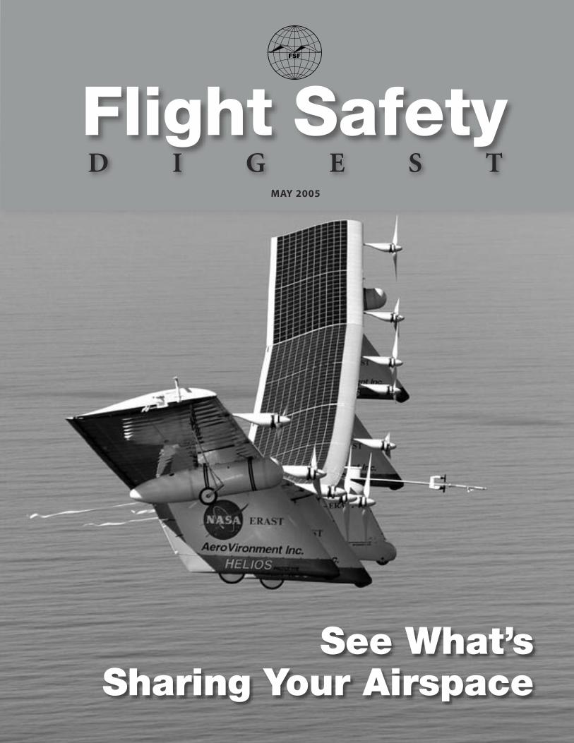
Cover photo: The AeroVironment Helios Prototype fl ew to nearly 97,000 feet in August 2001 in fl ight tests by the U.S. National Aeronautics and Space Administration (NASA). With a wingspan of 256 feet (78 meters), solar panels, fuel cells and 10 electric motors, it fl ew partly “to develop technologies to enable unmanned aerial vehicles (UAVs) to perform a variety of long-duration missions, including environmental monitoring and telecommunications-relay services,” NASA said. This UAV experienced control diffi culties at about 3,000 feet during its 10th fl ight in a restricted area near the Hawaiian island of Kauai, struck the Pacifi c Ocean and was destroyed on June 26, 2003. A similar UAV, Pathfi nder-Plus (see page 22), continues to be fl own for NASA research. (Photo: Carla Thomas, NASA)

1FLIGHT SAFETY FOUNDATION • FLIGHT SAFETY DIGEST • MAY 2005
See What’s Sharing Your AirspaceTrans-Pacific flights by a nearly 26,000-pound gross weight U.S. Air Force Global Hawk
unmanned aerial vehicle (UAV) helped drive the current quest for commercial applications. Flying
UAVs in civil airspace demands solutions to problems such as collision avoidance and failure of
data/communication links with a ground-based pilot thousands of miles from the aircraft.
— FSF EDITORIAL STAFF
Technological advances, military-industrial initiatives and fast-track regulatory activities are on the verge of launching a new era of routine
flight by unmanned aerial vehicles (UAVs) in civil airspace. Often defi ned as “aircraft designed to operate with no human pilot aboard,”1 UAVs also are called uninhabited air vehicles, remotely operated aircraft and other terms. For example, the U.S. Federal Aviation Administration (FAA) and the U.S. Department of Defense (DOD) have begun to replace “UAV” with “unmanned aircraft system” as their preferred term.2 Public interest in
UAVs has intensifi ed as news media cover military operations in Afghanistan and Iraq. Large UAVs routinely are fl own over these countries and con-trolled via satellite data link by a ground-based pilot situated in a ground control station in California, U.S.3 The typical remote-control system comprises the UAV, ground control station, control data link that operates at line-of-sight distances and/or over-the-horizon distances, and data/voice radio relay.
“UAVs will range in size from several ounces to thousands of pounds,” said a 2004 MITRE Corp. report for FAA. “Many will fl y slowly and lack
The General Atomics
Aeronautical Systems
Altair can fly at 52,000
feet and remain
airborne for more than
30 hours. The aircraft’s
uses include nautical
charting, fisheries
assessment and climate
research. (Photo: Tom
Tschida, NASA)
2 FLIGHT SAFETY FOUNDATION • FLIGHT SAFETY DIGEST • MAY 2005
S E E W H A T ’ S S H A R I N G Y O U R A I R S P A C E
maneuverability, whereas others will operate at very high speeds with great agility. … Further, the types of missions being planned for UAVs of the future are rarely point-to-point but typically in-volve some form of patterned fl ight or tracking activity that may include intermittent short-[term orbits] or long-term orbits.”4
The ground-based pilot’s location in a ground control station causes signifi cant limitations compared with pilots of manned aircraft.
“Rather than receiving direct sen-sory input from the environment in which his/her vehicle is operating, a [ground-based pilot] receives only that sensory information provided by on-board sensors via data link,”
said aerospace researchers at the University of Illinois, U.S. “Currently, this consists primarily of visual imagery covering a restricted fi eld of view. Sensory cues that are lost therefore include ambi-ent visual information, kinesthetic/vestibular input and sound. … [A ground-based pilot] can be said to perform in relative ‘sensory isolation’ from the vehicle under his/her control. … To the [ground-based pilot] of a UAV with a conventional display, turbulence is indicated solely by perturbations of the camera image provided by the UAV sensors.”5
Integration of military/government UAVs and commercial UAVs into civil airspace may occur sooner than many aviation professionals an-ticipate, based on the highly touted suitability of UAVs for dull, dirty and/or dangerous missions (i.e., fl ights that exceed human physical/mental stamina or subject pilots to environmental hazards or signifi cant safety/security threats).
Moreover, FAA Administrator Marion Blakey said in March 2005, “[Forecasts of air traffi c] present some enormous challenges and risks. And to a per-son here, we fully recognize that the current system cannot accommodate such huge new demand. It was never designed to handle the projected new mix of air traffi c in our skies. … In 2025, we could be looking at three times more passengers, opera-tions and cargo than we had in 2000 [in the United States]. We need a system that can accommodate
anything our imagination and entrepreneurs can serve up. Who would have dreamt 20 years ago that hailing a taxi could mean calling a very light jet? Or that the product you purchased over the Internet would arrive one day on a UAV? Twenty years ago, we called people like that dreamers. Today, they’re called investors.”6
As of early 2004, more than 40 countries oper-ated more than 80 types of UAVs, said the report of a European UAV task force. The performance of current UAVs varies widely in speed, altitude, mission duration and payload capability.7
“To date, approximately 90-plus percent of all funding for UAV systems is a direct result of national government requirements channeled through their military and defense program ele-ments,” the European task force report said. “The primary mission profi les are quite similar both on the military [side] and civil side; [they] are mainly earth observation … and communications.”
Most large UAVs currently being fl own in U.S. airspace carry radio-relay equipment that enables ground-based pilot–air traffi c control (ATC) voice communication to be conducted much as if the pilot were aboard an aircraft. This simplifi es com-munication and provides pilots of aircraft near a UAV with a method of situational awareness. Equipping small UAVs with radio-relay equipment for ATC communication often is not possible be-cause of payload limitations.8
“UAVs offer a unique range of features, most notably ultra-long endurance and high-risk mission acceptance, which cannot be reasonably performed by manned aircraft,” said the MITRE report. “These features — when coupled with advances in automation and sensor technologies, and the potential for cost savings — make a strong case for the eventual emergence of a robust civil, government and commercial UAV market.”
Some Divide UAVs Into Three Basic Categories
The UAV community and civil aviation authori-ties envision gradual integration of different
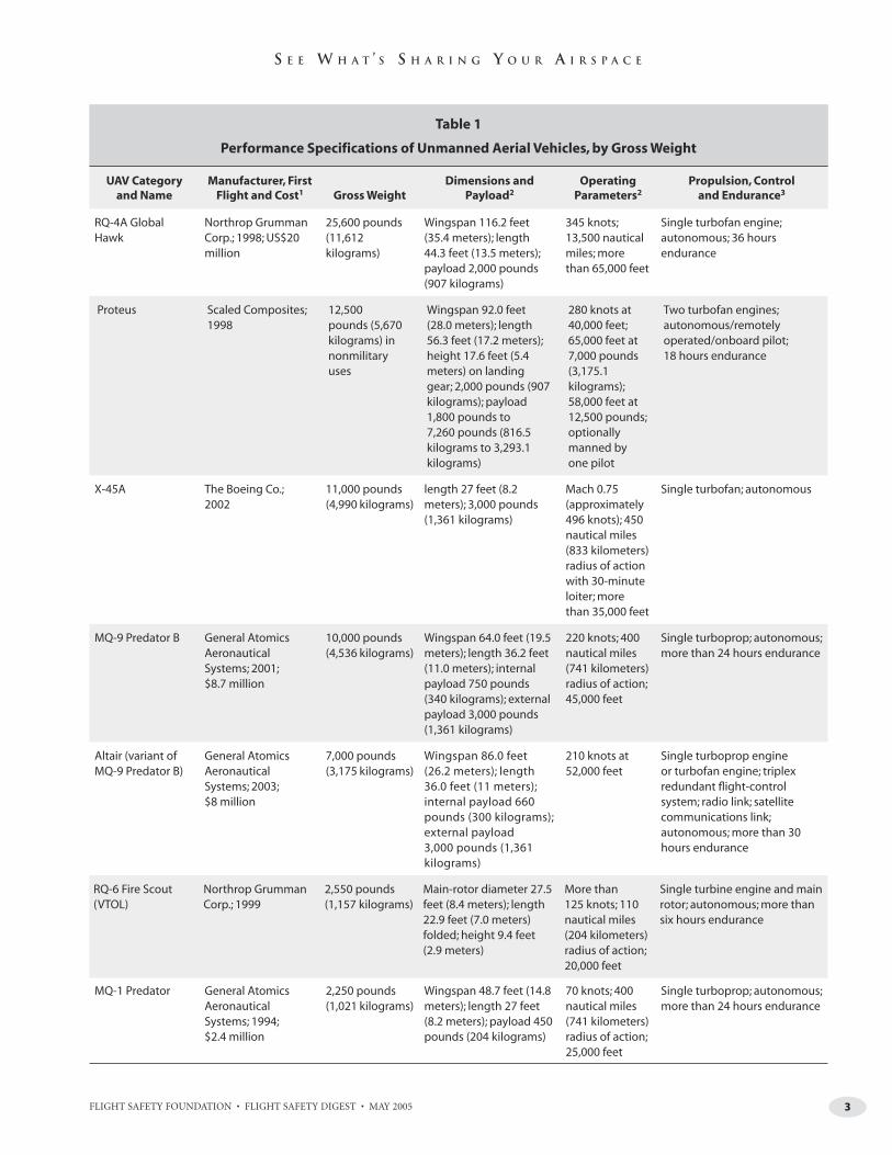
categories of UAVs into civil airspace. Table 1 (page 3) shows the performance specifi cations of several
Continued on page 5
3FLIGHT SAFETY FOUNDATION • FLIGHT SAFETY DIGEST • MAY 2005
S E E W H A T ’ S S H A R I N G Y O U R A I R S P A C E
Table 1
Performance Specifications of Unmanned Aerial Vehicles by Gross Weight (continued)
UAV Category and Name
Manufacturer, First Flight and Cost1 Gross Weight
Dimensions and Payload2
Operating Parameters2
Propulsion, Control and Endurance3
Table 1
Performance Specifications of Unmanned Aerial Vehicles, by Gross Weight
UAV Category and Name
Manufacturer, First Flight and Cost1 Gross Weight
Dimensions and Payload2
Operating Parameters2
Propulsion, Control and Endurance3
RQ-4A Global Hawk
Northrop Grumman Corp.; 1998; US$20 million
25,600 pounds(11,612 kilograms)
Wingspan 116.2 feet (35.4 meters); length 44.3 feet (13.5 meters); payload 2,000 pounds (907 kilograms)
345 knots; 13,500 nautical miles; more than 65,000 feet
Single turbofan engine; autonomous; 36 hours endurance
Proteus Scaled Composites; 1998
12,500 pounds (5,670 kilograms) in nonmilitary uses
Wingspan 92.0 feet (28.0 meters); length 56.3 feet (17.2 meters); height 17.6 feet (5.4 meters) on landing gear; 2,000 pounds (907 kilograms); payload 1,800 pounds to 7,260 pounds (816.5 kilograms to 3,293.1 kilograms)
280 knots at 40,000 feet; 65,000 feet at 7,000 pounds (3,175.1 kilograms); 58,000 feet at 12,500 pounds; optionally manned by one pilot
Two turbofan engines; autonomous/remotely operated/onboard pilot; 18 hours endurance
X-45A The Boeing Co.; 2002
11,000 pounds (4,990 kilograms)
length 27 feet (8.2 meters); 3,000 pounds (1,361 kilograms)
Mach 0.75 (approximately 496 knots); 450 nautical miles (833 kilometers) radius of action with 30-minute loiter; more than 35,000 feet
Single turbofan; autonomous
MQ-9 Predator B General Atomics Aeronautical Systems; 2001; $8.7 million
10,000 pounds (4,536 kilograms)
Wingspan 64.0 feet (19.5 meters); length 36.2 feet (11.0 meters); internal payload 750 pounds (340 kilograms); external payload 3,000 pounds (1,361 kilograms)
220 knots; 400 nautical miles (741 kilometers) radius of action; 45,000 feet
Single turboprop; autonomous; more than 24 hours endurance
Altair (variant of MQ-9 Predator B)
General Atomics Aeronautical Systems; 2003; $8 million
7,000 pounds (3,175 kilograms)
Wingspan 86.0 feet (26.2 meters); length 36.0 feet (11 meters); internal payload 660 pounds (300 kilograms); external payload 3,000 pounds (1,361 kilograms)
210 knots at 52,000 feet
Single turboprop engine or turbofan engine; triplex redundant fl ight-control system; radio link; satellite communications link; autonomous; more than 30 hours endurance
RQ-6 Fire Scout (VTOL)
Northrop Grumman Corp.; 1999
2,550 pounds (1,157 kilograms)
Main-rotor diameter 27.5 feet (8.4 meters); length 22.9 feet (7.0 meters) folded; height 9.4 feet (2.9 meters)
More than 125 knots; 110 nautical miles (204 kilometers) radius of action; 20,000 feet
Single turbine engine and main rotor; autonomous; more than six hours endurance
MQ-1 Predator General Atomics Aeronautical Systems; 1994; $2.4 million
2,250 pounds (1,021 kilograms)
Wingspan 48.7 feet (14.8 meters); length 27 feet (8.2 meters); payload 450 pounds (204 kilograms)
70 knots; 400 nautical miles (741 kilometers) radius of action; 25,000 feet
Single turboprop; autonomous; more than 24 hours endurance

4 FLIGHT SAFETY FOUNDATION • FLIGHT SAFETY DIGEST • MAY 2005
S E E W H A T ’ S S H A R I N G Y O U R A I R S P A C E
Table 1
Performance Specifications of Unmanned Aerial Vehicles by Gross Weight (continued)
UAV Category and Name
Manufacturer, First Flight and Cost1 Gross Weight
Dimensions and Payload2
Operating Parameters2
Propulsion, Control and Endurance3
Perseus B Aurora Flight Sciences; 1994
2,200 pounds (998 kilograms)
Wingspan 71.5 feet (21.8 meters); length 25 feet (7.6 meters); height 12 feet (3.7 meters); payload 264 pounds (120 kilograms)
52 knots; 1,600 nautical miles (2,963 kilometers) point-to-point; 60 nautical miles (111 kilometers) radius of action; 62,000 feet
Single reciprocating engine and propeller; remotely operated (includes fl ight termination system with parachute); 24 hours endurance
RQ-5 Hunter Israel Aircraft Industries/Malat and Northrop Grumman Corp.; 1990; $1.2 million
1,600 pounds (726 kilograms)
Wingspan 29.2 feet (8.9 meters); length 23.0 feet (7.0 meters); payload 200.0 pounds (90.7 kilograms)
100 knots; 144 nautical miles (267 kilometers) radius of action; 15,000 feet
Two reciprocating gasoline engines and propellers; autonomous; 11.6 hours endurance
Pathfi nder-Plus AeroVironment; 1998 700.0 pounds (317.5 kilograms)
Wingspan 121.0 feet (36.9 meters); length 11.0 feet (3.4 meters); payload 700.0 pounds (317.5 kilograms)
Slow-fl ying ultralight; unspecifi ed range; 82,000 feet
Eight solar-powered electric motors with propellers; remotely operated via satellite link; unspecifi ed endurance
RQ-2 Pioneer Israel Aircraft Industries/Pioneer UAVs; 1985
452 pounds (205 kilograms)
Wingspan 17.0 feet (5.2 meters); length 14 feet (4.3 meters); payload 75 pounds (34 kilograms)
80 knots; 100 nautical miles (185 kilometers) radius of action; 15,000 feet
Single reciprocating gasoline engine and propeller; autonomous; fi ve hours endurance
RQ-7 Shadow 200 Israel Aircraft Industries; 1998; $325,000
327 pounds (148 kilograms)
Wingspan 12.8 feet (3.9 meters); length 11.2 feet (3.4 meters); payload 60.0 pounds (27.2 kilograms)
82 knots; 68 nautical miles (126 kilometers) radius of action; 15,000 feet; launched by catapult rail; recovered by arresting equipment
Single reciprocating engine and propeller; autonomous/remotely operated; four hours endurance
RMAX Type IIG (VTOL)
Yamaha Motor Co.; 2003
207 pounds (94 kilograms)
Main-rotor diameter 10.20 feet (3.12 meters); length 11.90 feet (3.63 meters); height 3.54 feet (1.08 meters); payload 61.7 pounds (28.0 kilograms)
11 knots for crop dusting; 492 feet (150 meters) typical distance from operator; 16.4 feet for crop dusting to 328 feet for aerial imagery
Reciprocating water-cooled gasoline engine; autonomous fl ight termination/return to takeoff point using GPS sensor and gyroscopic sensor; remotely operated by maneuver command and hover; one hour endurance
Bird Eye 500 Israel Aircraft Industries/Malat; 2004
77.2 pounds (35.0 kilograms)
Wingspan 6.6 feet (2.0 meters); length 5.2 feet (1.6 meters); payload 30 ounces (850 grams)
60 knots; area of 39 square miles (10,000 hectares); 1,000 feet
Single electric motor and propeller (hand launch or bungee-cord launch); autonomous with in-fl ight waypoint control; more than one hour endurance
5FLIGHT SAFETY FOUNDATION • FLIGHT SAFETY DIGEST • MAY 2005
S E E W H A T ’ S S H A R I N G Y O U R A I R S P A C E
Table 1
Performance Specifications of Unmanned Aerial Vehicles by Gross Weight (continued)
UAV Category and Name
Manufacturer, First Flight and Cost1 Gross Weight
Dimensions and Payload2
Operating Parameters2
Propulsion, Control and Endurance3
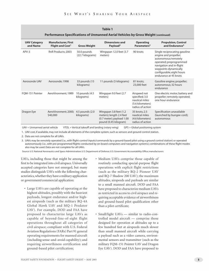
UAVs, including those that might be among the fi rst to be integrated into civil airspace. Universally accepted categories have not emerged, but many studies distinguish UAVs with the following char-acteristics, whether they have a military application or government/commercial application:
• Large UAVs are capable of operating at the highest altitudes, possibly with the heaviest payloads, longest endurance and/or high-est airspeeds (such as the military RQ-4A Global Hawk UAV and MQ-1 Predator UAV). For example, DOD and FAA have proposed to characterize large UAVs as capable of beyond-line-of-sight flight operations throughout all categories of civil airspace; compliant with U.S. Federal Aviation Regulations (FARs) Part 91 general operating requirements for manned aircraft (including sense-and-avoid capability); and requiring airworthiness certification and ground-based pilot certification;
• Medium UAVs comprise those capable of routinely conducting special-purpose flight operations with explicit flight restrictions (such as the military RQ-2 Pioneer UAV and RQ-7 Shadow 200 UAV); the maximum altitudes, airspeeds and payloads are similar to a small manned aircraft. DOD and FAA have proposed to characterize medium UAVs as restricted in access to civil airspace and re-quiring acceptable evidence of airworthiness and ground-based pilot qualification other than a pilot certificate;
• Small/light UAVs — similar to radio-con-trolled model aircraft — comprise those designed for operation at altitudes up to a few hundred feet at airspeeds much slower than small manned aircraft while carrying a payload such as a video camera, environ-mental sensors and transmitter (such as the military FQM-151 Pointer UAV and Dragon Eye UAV). DOD and FAA have proposed to
APV-3 RnR Products; 2003 50.0 pounds (22.7 kilograms)
Wingspan 12.0 feet (3.7 meters)
90 knots Single reciprocating gasoline engine and propeller; autonomous/remotely operated; preprogrammed navigation and in-fl ight waypoints dynamically confi gurable; eight hours endurance at 45 knots
Aerosonde UAV Aerosonde; 1998 33 pounds (15 kilograms)
11 pounds (5 kilograms) 81 knots; 23,000 feet
Gasoline engine; propeller; autonomous; 32 hours endurance
FQM-151 Pointer AeroVironment; 1989 10 pounds (4.5 kilograms)
Wingspan 9.0 feet (2.7 meters)
Airspeed not specifi ed; 3.0 nautical miles (5.6 kilometers) radius of action
One electric motor, battery and propeller; remotely operated; one hour endurance
Dragon Eye AeroVironment; 2000; $40,000
4.5 pounds (2.0 kilograms)
Wingspan 3.8 feet (1.2 meters); length 2.4 feet (0.7 meter); payload 1.00 pound (0.45 kilogram)
35 knots; 2.5 nautical miles (4.6 kilometers) radius of action
Specifi cation unavailable (launched by bungee cord); autonomous
UAV = Unmanned aerial vehicle VTOL = Vertical takeoff and landing (rotary wing) GPS = Global positioning system
1. UAV cost, if available, may not include all elements of the complete system, such as sensors and ground control station.
2. Data are not complete for all UAVs.
3. UAVs may be remotely operated (i.e., with fl ight-control inputs/commands by a ground-based pilot using a ground control station) or operated autonomously (i.e., with pre-programmed fl ights conducted by on-board computers and navigation systems); combinations of these fl ight modes also may be used. Data are not complete for all UAVs.
Source: U.S. National Aeronautics and Space Administration; U.S. Department of Defense; U.S. Government Accountability Offi ce; manufacturers

6 FLIGHT SAFETY FOUNDATION • FLIGHT SAFETY DIGEST • MAY 2005
S E E W H A T ’ S S H A R I N G Y O U R A I R S P A C E
characterize small/light UAVs as generally limited to line-of-sight operations, with the operator providing acceptable evidence of airworthiness and ground-based pilot/user qualification other than a pilot certificate. National regulations typically differentiate between a small/light UAV and a model air-craft based on criteria such as aircraft weight and/or its use for commercial purposes.9
Recent examples of the state of UAV technology include the following:
• One ground-based pilot simultaneously com-manded flights by two turbofan-powered Boeing X-45A UAVs in flight formations in 2004, and accurately controlled the time of arrival for multiple-UAV flights over specified geographic locations;10
• During March 2002 flight tests near Las Cruces, New Mexico, U.S., a Proteus aircraft with a safety pilot aboard was flown by a ground-based pilot while several “coopera-tive” aircraft with operating transponders
approached the Proteus from various angles. The cooperative aircraft maneuvered indi-vidually and in converging groups of two, and included a U.S. National Aeronautics and Space Administration (NASA) F/A-18 Hornet jet. In 18 simulated-conflict scenarios, sensors — combining a radio-based traffic-advisory system and infrared/radar technology — de-tected the collision threats and transmitted traffic advisories to the ground-based pilot, who altered the flight path in time for colli-sion avoidance in all scenarios;11
• In April 2003, the Proteus was flown by a ground-based pilot while several “noncoop-erative” aircraft without operating transpon-ders — ranging from a glider to the NASA F/A-18 — approached from various angles for 20 simulated-conflict scenarios. “For this series, the [Proteus was] equipped with a 35-gigahertz radar system [designed] to detect any approaching aircraft on a potential collision course, regardless of whether the intruder [was] equipped with an operating transponder,” NASA said. The ground-based
The military Boeing
X-45A unmanned aerial
vehicle is designed
to fly at Mach 0.75
(approximately 496
knots) at 35,000 feet.
(Illustration: The Boeing Co.)

7FLIGHT SAFETY FOUNDATION • FLIGHT SAFETY DIGEST • MAY 2005
S E E W H A T ’ S S H A R I N G Y O U R A I R S P A C E
pilot altered the UAV’s flight path in response to data received from the on-board radar system, maintaining a minimum 500-foot (152-meter) distance from the intruder air-craft in all scenarios. “The detection ranges were a little less than we expected but varied greatly from about 2.5 [nautical miles] to 6.5 nautical miles [4.6 kilometers to 12.0 kilo-meters], based on the structure and radar cross-section of the target aircraft,” NASA said;12
• In March 2005, two APV-3 UAVs flown along computer-generated flight paths dem-onstrated the ability, without ground-based pilot intervention, to search in a rectangular grid pattern above a simulated forest fire while simultaneously conducting synchro-nized flight maneuvers that avoided obstacles, NASA said;13
• News media reports said that UAVs were used by the defense ministry of India to help locate survivors in distress, direct helicopter rescue operations and manage recovery
operations during the country’s response to the December 2004 Indian Ocean tsunami.14
• Beginning in 2004, U.S. Army RQ-5 Hunter UAVs were used for reconnaissance flights by the U.S. Department of Homeland Security along the Arizona border with Mexico 90 miles (145 kilometers) southeast of Tucson, Arizona, U.S. The UAV manufac-turer, Northrop Grumman Corp., said that the capabilities of these UAVs include “sus-tained autonomous flight, high-resolution day and nighttime visual and infrared sen-sors, integrated [global positioning system (GPS)]-location systems, and the ability to relay communication signals to border-patrol agents. … Individuals on the ground may be unaware of this law-enforcement activity because of the [UAV’s inconspicu-ous] visual profile at altitude and its quiet engine.”15
• A civilian UAV flight in the Netherlands was conducted by Israel Aircraft Industries/Malat in June 2004. The Bird Eye 500 UAV was flown
The Scaled Composites
Proteus aircraft, right,
and a NASA F/A-18
Hornet flew near Las
Cruces, New Mexico,
U.S., in 2002 during
testing of collision-
avoidance systems
for unmanned aerial
vehicles. (Photo: Tom
Tschida, NASA)
8 FLIGHT SAFETY FOUNDATION • FLIGHT SAFETY DIGEST • MAY 2005
S E E W H A T ’ S S H A R I N G Y O U R A I R S P A C E
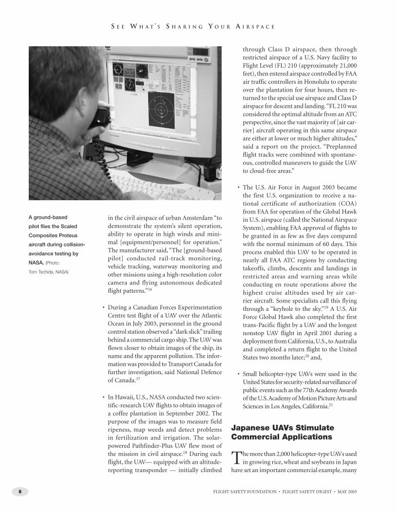
in the civil airspace of urban Amsterdam “to demonstrate the system’s silent operation, ability to operate in high winds and mini-mal [equipment/personnel] for operation.” The manufacturer said, “The [ground-based pilot] conducted rail-track monitoring, vehicle tracking, waterway monitoring and other missions using a high-resolution color camera and flying autonomous dedicated flight patterns.”16
• During a Canadian Forces Experimentation Centre test flight of a UAV over the Atlantic Ocean in July 2003, personnel in the ground control station observed a “dark slick” trailing behind a commercial cargo ship. The UAV was flown closer to obtain images of the ship, its name and the apparent pollution. The infor-mation was provided to Transport Canada for further investigation, said National Defence of Canada.17
• In Hawaii, U.S., NASA conducted two scien-tific-research UAV flights to obtain images of a coffee plantation in September 2002. The purpose of the images was to measure field ripeness, map weeds and detect problems in fertilization and irrigation. The solar-powered Pathfinder-Plus UAV flew most of the mission in civil airspace.18 During each flight, the UAV— equipped with an altitude-reporting transponder — initially climbed
through Class D airspace, then through restricted airspace of a U.S. Navy facility to Flight Level (FL) 210 (approximately 21,000 feet), then entered airspace controlled by FAA air traffic controllers in Honolulu to operate over the plantation for four hours, then re-turned to the special use airspace and Class D airspace for descent and landing. “FL 210 was considered the optimal altitude from an ATC perspective, since the vast majority of [air car-rier] aircraft operating in this same airspace are either at lower or much higher altitudes,” said a report on the project. “Preplanned flight tracks were combined with spontane-ous, controlled maneuvers to guide the UAV to cloud-free areas.”
• The U.S. Air Force in August 2003 became the first U.S. organization to receive a na-tional certificate of authorization (COA) from FAA for operation of the Global Hawk in U.S. airspace (called the National Airspace System), enabling FAA approval of flights to be granted in as few as five days compared with the normal minimum of 60 days. This process enabled this UAV to be operated in nearly all FAA ATC regions by conducting takeoffs, climbs, descents and landings in restricted areas and warning areas while conducting en route operations above the highest cruise altitudes used by air car-rier aircraft. Some specialists call this flying through a “keyhole to the sky.”19 A U.S. Air Force Global Hawk also completed the first trans-Pacific flight by a UAV and the longest nonstop UAV flight in April 2001 during a deployment from California, U.S., to Australia and completed a return flight to the United States two months later;20 and,
• Small helicopter-type UAVs were used in the United States for security-related surveillance of public events such as the 77th Academy Awards of the U.S. Academy of Motion Picture Arts and Sciences in Los Angeles, California.21
Japanese UAVs StimulateCommercial Applications
The more than 2,000 helicopter-type UAVs used in growing rice, wheat and soybeans in Japan
have set an important commercial example, many
A ground-based
pilot flies the Scaled
Composites Proteus
aircraft during collision-
avoidance testing by
NASA. (Photo:
Tom Tschida, NASA)

9FLIGHT SAFETY FOUNDATION • FLIGHT SAFETY DIGEST • MAY 2005
S E E W H A T ’ S S H A R I N G Y O U R A I R S P A C E
specialists said. One of the most widely used types — the Yamaha Motor Co. RMAX series — has been fl own for observation of volcanic eruptions with an on-board video camera and video link. This type of UAV also has been fl own for plant-growth observations, airborne-radiation detection and bridge inspections.
These agricultural UAVs typically are operated at altitudes of 10 feet to 16 feet and an airspeed of 11 knots. The portable ground control station allows the ground-based pilot to fly the UAV within a 200-meter (656-foot) line-of-sight dis-tance. Most Japanese agricultural UAVs operate by line-of-sight data link at altitudes of less than 164 feet. For observation missions, some of these helicopter-type UAVs can operate autonomously — i.e., with programmed fl ights conducted by on-board computers and navigation systems — using beyond-the-horizon data links at altitudes up to 492 feet. Changes to Japanese civil aviation regulations will be required to routinely fl y UAVs at higher altitudes in civil airspace.22 Under the current system, more than 5,500 licensed ground-based pilots are available to operate the agricul-tural UAVs for application of liquid/granular crop insecticide across 500,000 acres [202,343 hectares] of agricultural land per year.23
In one agricultural test of UAVs in the United States, a NASA APV-3 was used in August 2003 and spring 2005 to obtain digital imagery of a 5,000-acre (2,023-hectare) vineyard near Monterey, California, to map differences in the vigor of grape plants and to test airborne frost-detection sensors. In another multi-year project begun in 2001, a NASA Altus II UAV with infrared sensors has been used to demonstrate methods of wildfi re detection and tactical fi re fi ghting.24
The MITRE report said that near-term uses of nonmilitary government UAVs also may include “emergency response; … search and rescue; forest-fi re monitoring; communications relay; fl ood mapping; high-altitude imaging; nuclear-biological-chemical sensing/tracking; traffi c mon-itoring; humanitarian aid; land-use mapping; and chemical and petroleum spill monitoring.”25
Expected commercial applications for UAVs include “crop monitoring; … motion pic-ture [production]; communications relay; utility inspection [pipelines/power lines];
multi-sensor station-keeping [maintaining a position in the sky]; news media support; aerial advertising; fi sh spotting; surveying and mapping; commercial imaging; cargo; and commercial se-curity.”26 Although UAV commercial cargo fl ights often are envisioned, predicting when such fl ights might begin depends on many variables.
One U.S. air cargo company said, “Since its in-ception in 1986, UPS Airlines has maintained a primary goal: provide quality service to custom-ers while operating in a safe and effi cient manner. While this includes taking advantage of the latest technology, we don’t see UAVs as part of our fl eet in the near future.”27
Scientifi c-research applications are creating many new markets, and NASA leases payload space/time on UAVs as large as the Altair to qualifi ed research organizations, and has considered the Global Hawk. In one consultant’s 2004 business model for NASA, the purchase price of an Altair was estimated to be US$8 million and associated
The Yamaha RMAX
Type IIG — weighing
207 pounds (94
kilograms) with a
main-rotor diameter of
10.2-feet (3.1 meters)
— applies insecticides
from 16 feet above
crops in Japan while
flying at 11 knots.
(Photo: Yamaha Motor Corp.)

10 FLIGHT SAFETY FOUNDATION • FLIGHT SAFETY DIGEST • MAY 2005
S E E W H A T ’ S S H A R I N G Y O U R A I R S P A C E
ground equipment $6 million. The report said that U.S. Department of Homeland Security costs for Predator demonstration fl ights were $2,358 per fl ight hour for 106 fl ight hours in one 17-day series and $5,469 per fl ight hour for 128 fl ight hours in one fi ve-day series, all in late 2003.28 Worldwide, the nonmilitary uses of UAVs primarily have been in public-sector services, scientifi c research or aerospace research and development.
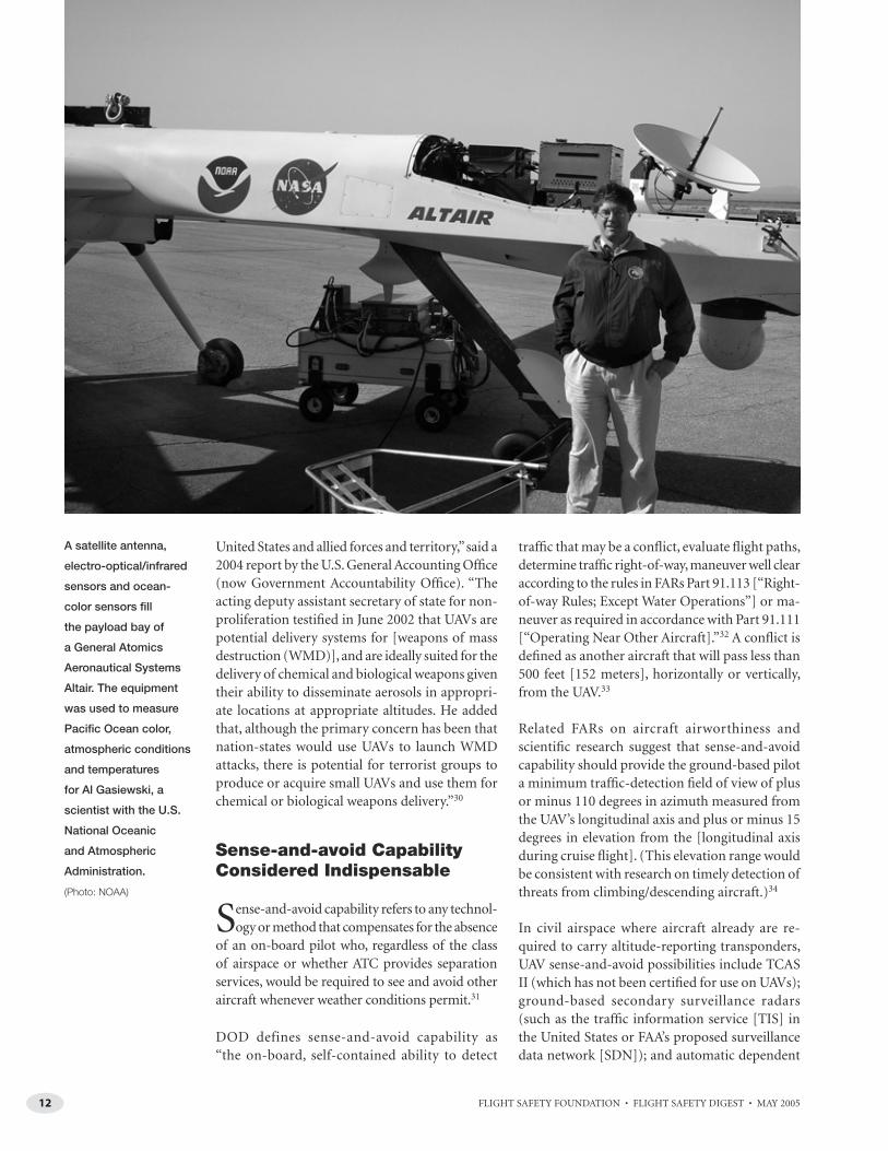
As an example of such scientifi c research, NASA and the U.S. National Oceanic and Atmospheric Administration (NOAA) in April and May 2005 conducted a series of Altair UAV fl ights off the coast of Southern California near the Channel Islands.29
“The goal … is to demonstrate the operational capabilities of [UAVs] for science missions related to oceanic and atmospheric research, climate research, marine-sanctuary mapping and enforcement, nautical charting, and fi sher-ies assessment and enforcement,” said Thomas J. Cassidy Jr., president and CEO of General Atomics Aeronautical Systems.
“UAVs will allow us to see weather before it hap-pens, detect toxins before we breathe them and dis-cover harmful and costly algal blooms before the fi sh do — and there is an urgency to more effectively address these issues,” said Conrad C. Lautenbacher
Jr., undersecretary of commerce for oceans and at-mosphere, and NOAA administrator.
“NASA is glad to see that UAVs are being used for more and more diverse and important opera-tions, and we’re looking forward to routine access to [U.S. airspace] that will allow UAVs to play an expanding role in earth science and other types of missions,” said Terrence Hertz, deputy associate administrator for technology, NASA Aeronautics Research Mission Directorate.
Other objectives include atmospheric sampling and imaging of the Channel Islands National Marine Sanctuary “to examine shorelines and evaluate the potential for marine enforcement surveillance.”
Complex Impediments DriveResearch on Many Fronts
Integration of UAVs into civil airspace faces a number of challenges. The European UAV task
force, for example, said that operators of UAVs may have diffi culty complying with international rules for avoiding collisions; for detecting visual signals from ATC; for preventing unlawful inter-ference with a UAV, data link or ground-control station; and for observation by the ground-based
The RnR Products
APV-3 has an eight-hour
endurance at 45 knots
and a maximum cruise
airspeed of 90 knots.
Shannon Kolensky, a
cooperative-program
student, holds the
aircraft during engine
runup. (Photo: Tom Tschida,
NASA)

11FLIGHT SAFETY FOUNDATION • FLIGHT SAFETY DIGEST • MAY 2005
S E E W H A T ’ S S H A R I N G Y O U R A I R S P A C E
pilot of visual signals from the pilot of an inter-cepting aircraft.
Overall, recent studies point to the following re-quirements for large UAVs and medium UAVs to operate in civil airspace:
• On-board sense-and-avoid capability — in-dependent of the data link to the ground-control station — to help prevent in-flight collision;
• On-board capability to autonomously pre-vent a collision with terrain or obstacles;
• Adequate UAV airworthiness and reliability;
• A method for autonomous flight continuation and termination by the UAV if failure occurs in the data link to the ground control station;
• A method for the UAV to comply with ATC instructions — such as direct commands to
the UAV from an air traffic controller — if a failure occurs in communication between ATC and the ground-based pilot;
• A backup system for approach and landing if UAV navigation based on GPS fails;
• Mitigation of human factors risks in UAV operations, such as flight handovers between ground-based pilots, procedural errors or fatigue/boredom during flight monitoring; and,
• Mitigation of environmental risks to UAVs such as weather, bird strikes and turbulence.
Moreover, security of UAVs and ground control stations is essential because of the possibility that they could be used for hostile purposes, U.S. gov-ernment reports said.
“UAVs represent an inexpensive means of launch-ing chemical and biological attacks against the
Long, narrow wings
of the General Atomics
Aeronautical Systems
(GA-ASI) Altair enable
NASA to conduct 210-
knot flights at 52,000
feet. (Photo: NASA –
Alan Waide, GA-ASI)
12 FLIGHT SAFETY FOUNDATION • FLIGHT SAFETY DIGEST • MAY 2005
S E E W H A T ’ S S H A R I N G Y O U R A I R S P A C E
United States and allied forces and territory,” said a 2004 report by the U.S. General Accounting Offi ce (now Government Accountability Offi ce). “The acting deputy assistant secretary of state for non-proliferation testifi ed in June 2002 that UAVs are potential delivery systems for [weapons of mass destruction (WMD)], and are ideally suited for the delivery of chemical and biological weapons given their ability to disseminate aerosols in appropri-ate locations at appropriate altitudes. He added that, although the primary concern has been that nation-states would use UAVs to launch WMD attacks, there is potential for terrorist groups to produce or acquire small UAVs and use them for chemical or biological weapons delivery.”30
Sense-and-avoid CapabilityConsidered Indispensable
Sense-and-avoid capability refers to any technol-ogy or method that compensates for the absence
of an on-board pilot who, regardless of the class of airspace or whether ATC provides separation services, would be required to see and avoid other aircraft whenever weather conditions permit.31
DOD defines sense-and-avoid capability as “the on-board, self-contained ability to detect
traffi c that may be a confl ict, evaluate fl ight paths, determine traffi c right-of-way, maneuver well clear according to the rules in FARs Part 91.113 [“Right-of-way Rules; Except Water Operations”] or ma-neuver as required in accordance with Part 91.111 [“Operating Near Other Aircraft].”32 A confl ict is defi ned as another aircraft that will pass less than 500 feet [152 meters], horizontally or vertically, from the UAV.33
Related FARs on aircraft airworthiness and scientifi c research suggest that sense-and-avoid capability should provide the ground-based pilot a minimum traffi c-detection fi eld of view of plus or minus 110 degrees in azimuth measured from the UAV’s longitudinal axis and plus or minus 15 degrees in elevation from the [longitudinal axis during cruise fl ight]. (This elevation range would be consistent with research on timely detection of threats from climbing/descending aircraft.)34
In civil airspace where aircraft already are re-quired to carry altitude-reporting transponders, UAV sense-and-avoid possibilities include TCAS II (which has not been certifi ed for use on UAVs); ground-based secondary surveillance radars (such as the traffi c information service [TIS] in the United States or FAA’s proposed surveillance data network [SDN]); and automatic dependent
A satellite antenna,
electro-optical/infrared
sensors and ocean-
color sensors fill
the payload bay of
a General Atomics
Aeronautical Systems
Altair. The equipment
was used to measure
Pacific Ocean color,
atmospheric conditions
and temperatures
for Al Gasiewski, a
scientist with the U.S.
National Oceanic
and Atmospheric
Administration.
(Photo: NOAA)

13FLIGHT SAFETY FOUNDATION • FLIGHT SAFETY DIGEST • MAY 2005
S E E W H A T ’ S S H A R I N G Y O U R A I R S P A C E
surveillance–broadcast (ADS-B, assuming that the aircraft and UAVs carry this equipment in the future). Much of the research into sense-and-avoid methods for airspace where threat aircraft may not carry altitude-reporting transponders has focused on airborne primary radar, airborne passive infrared sensors, airborne passive visual sensors, ground-based primary radar (i.e., with horizontal threat data provided to ground-based pilots by ATC via landline communication) or combinations of these methods.35
In theory, routine authorization of UAV opera-tions in civil airspace could be accomplished more readily in some airspace than other airspace, said a report by Massachusetts (U.S.) Institute of Technology (MIT) Lincoln Laboratory. MIT researchers currently are studying how TCAS II with resolution advisories could be employed on the Global Hawk.36
“A see-and-avoid capability is seldom needed in Class A airspace and, because of the high speeds typically found at these altitudes, the effectiveness of see-and-avoid is minimal,” the report said. “The most challenging requirements for [UAV] see-and-avoid in Class E airspace occur below 10,000 feet, where VFR traffic is permitted to fly without transponders.”
The researchers have considered the possibility that different methods of providing the required UAV safety level may be required in different airspace rather than the same methods for all airspace.
“[A UAV] that fl ies exclusively in Class A airspace would encounter only other IFR [instrument fl ight rules] traffi c and would receive positive separation control by ATC,” the report said. “It is possible that the necessary improvement in safety could be achieved merely by equipping such [a UAV] with a 25-foot altitude-reporting Mode S transponder, a reliable low-latency communication link between ATC and the [ground-based pilot], and a means of handling lost link and emergency (e.g., engine failure) operations. In this case, safety analysis need not await the defi nition of new surveillance and avoidance algorithms.”
Problems in using current aircraft collision-avoidance technology for UAVs, however, include the differences in typical fl ight paths within a given type of airspace.
“Global Hawk, for example, flies at relatively low airspeed and high climb rate, resulting in a steeper climb profi le than typically occurs with jet transports,” said another MIT Lincoln Laboratory report. “As a result, encounters with Global Hawk may involve a higher rate of high-vertical-rate situations than is refl ected in the existing encoun-ter models [i.e., software models that can generate millions of air-traffi c-encounter situations based on close encounters in actual air traffi c radar data in specifi c airspace].”37
Nevertheless, other specialists have voiced con-cerns about the use of TCAS II for UAVs, primar-ily because UAVs do not fi t original assumptions about how TCAS would be used.
“First, the current surveillance, display and algo-rithm designs of TCAS were developed and vali-dated for aircraft with on-board pilots,” one MIT Lincoln Laboratory report said. “[International Civil Aviation Organization (ICAO)] panels … have advised against using existing TCAS on [UAVs], citing in particular interactions with other aircraft carrying [airborne collision avoid-ance systems (ACAS)]. Additionally, [a working group of the ICAO panel] has stated that the ICAO mandate requiring TCAS on large piloted aircraft does not apply to [UAVs]. … A second concern is that TCAS was never intended to replace see-and-avoid. … Although pilots routinely monitor their TCAS traffi c displays when fl ying in high-density airspace and depend upon them to verify the operating integrity of their TCAS equipment, the displayed information by itself is not adequate to support avoid-ance maneuvers.”38
The TCAS II design also assumes specific pilot-response times — five seconds in the ICAO TCAS standard — to a resolu-tion advisory, but ground-based pilots would operate in an en-vironment involving different response times.
“Response times for a [ground-based pilot] could differ both due to communication latency and to alternate control methods such as the use of a computer mouse

14 FLIGHT SAFETY FOUNDATION • FLIGHT SAFETY DIGEST • MAY 2005
S E E W H A T ’ S S H A R I N G Y O U R A I R S P A C E
rather than a control yoke,” said one report. “Remote control delays could decrease maneuver effectiveness and retard or negate TCAS–TCAS coordination. Lack of visual cues to check TCAS integrity or maneuver reasonableness could also increase collision risk.” (Latency of the voice link between a ground-based pilot and ATC may be one second or more, and may increase the probability of mistimed responses to transmissions, possibly requiring a dedicated communication link for UAV fl ights in relatively congested airspace, the report said.)39
ICAO working groups have recommended that for the near future, UAVs carry 25-foot altitude-reporting Mode S transponders and not be equipped with TCAS II. “Mode S equipage would allow ground controllers [ATC] and TCAS-equipped aircraft to track the [UAV] with precision, and TCAS[-equipped aircraft] and other controlled aircraft could maneuver to avoid the [UAV],” a MIT Lincoln Laboratory report said.40
The U.K. Civil Aviation Authority (CAA) in 2004 said that current technology and research have not yet enabled U.K. regulators to specify an acceptable sense-and-avoid capability for UAVs.
U.K. CAA said, “The CAA policy on UAV sense-and-avoid criteria is as follows: The overriding principle when assessing if a proposed UAV sense-and-avoid criterion is acceptable is that it should not introduce a greater hazard than currently exists. … From these discussions [with UAV-community representatives] and its own de-liberations, the CAA has concluded that the full range of parameters which may have to be taken into account in any solution of the sense-and-avoid problem has yet to be established. … Any agreed sense-and-avoid criteria must be acceptable to other existing airspace users.”41
Similarly, a 2004 U.S. Air Force report said, “At this point in the development of [a sense-and-avoid] system, we do not have all the information neces-sary to establish a defensible and tangible value for [equivalent level of safety comparable to manned aircraft].”42
Regarding UAV navigation, a DOD report said that current GPS-based systems generally meet standards for military operations without redundancy and without reliance on ground-based navigation aids.
“However, UAVs have a diminished prospect for relief since, unlike [the pilot of a] manned
U.S. Air Force
crewmembers at
Beale Air Force Base,
California, U.S., check
their squadron’s first
Northrop Grumman
RQ-4A Global Hawk,
which can cruise at 345
knots at 65,000 feet.
(Photo: John Schwab,
U.S. Air Force)

15FLIGHT SAFETY FOUNDATION • FLIGHT SAFETY DIGEST • MAY 2005
S E E W H A T ’ S S H A R I N G Y O U R A I R S P A C E
aircraft, a [ground-based pilot] cannot readily fall back on dead reckoning, contact navigation and map reading in the same sense that a manned-aircraft [pilot can use these backup methods],” the report said.43
Therefore, the absence of an on-board pilot chang-es the nature of the risk of the UAV colliding in fl ight with another aircraft, another UAV or birds, or striking terrain, water, obstacles or people on the ground. Both scenarios have been computer-simulated for UAVs in various studies.
Visual Methods Aim toPrevent Midair Collisions
Making UAVs visually conspicuous to the pi-lots of manned aircraft and to other UAVs
will require a variety of methods to complement sense-and-avoid capability. The European UAV task force said that, subject to further research, this may be a reason to require UAVs to display anti-collision lights and navigation lights 24 hours a day.
“For [crews of] manned aircraft, avoiding colli-sions with UAVs may yield additional complica-tions,” the task force said. “If a crew separates by see-and-avoid, it may misread the distance to a UAV if its size differs signifi cantly from that of a similarly shaped manned aircraft. [This may occur only] if the crew can distinguish that it is a UAV at all. Such UAVs shall be visually distinguishable from manned aircraft, from any aspect angle. It may not be possible to achieve this by distinctive color schemes [which] may not be visible from all angles) or [by] distinctive lighting (the UAV may be too small to carry additional battery power). A UAV may need a method of indicating to a manned aircraft close by that the UAV is aware of the presence of the other aircraft (and taking appropriate action).”
Autonomous flight continuation/termination after failure of a UAV’s data link to the ground control station could involve several methods, based on military UAV practices.
“In the event of lost command and control, mili-tary UAVs are typically programmed to climb to a predefi ned altitude to attempt to reestablish contact,” said a DOD report. “If contact is not
reestablished in a given time, the UAV can be pre-programmed to retrace its outbound route home, fl y direct to home or continue its mission. With re-spect to lost communications between the ground control stations and the UAV, or the UAV and ATC, however, there is no procedure for a communica-tions-out recovery. … Remarkably, most lost-link situations bear a striking resemblance to [no-radio IFR operations], and UAVs would enhance their predictability by autonomously following [this] guidance. … [Nevertheless,] UAVs, even with an adequate sense-and-avoid system (autonomous) would enhance overall safety by continuing to fl y IFR [after encountering visual meteorological conditions].”44
“Radio-frequency jamming and unintentional interference primarily increase the workload of [ground-based] pilots and air traffi c controllers when aircraft carry backup systems,” said the 2002 DOD UAV roadmap of broad plans. “For systems solely dependent on GPS, loss of service leaves UAVs to rely on [inertial-navigation] systems, none of which, in today’s [military] UAVs, have drift rates allowing the successful completion of a sortie through to landing,” DOD said.
RTCA Accepts Challenge ofSetting UAV Standards
Among major efforts in the United States for accelerated integration of UAVs into
civil airspace is RTCA Special Committee 203, Minimum Performance Standards for Unmanned Aircraft Systems and Unmanned Aircraft, which conduct-ed its fi rst meeting in December 2004. Members include representatives of government, military services, aca-demia, manufacturers, an air traffi c controller association, pilot unions and airlines. The committee initially is scheduled to develop minimum aviation system performance stan-dards for UAVs by December 2005; command, control and communi-cation systems for UAVs by June 2006; and sense-and-avoid systems for UAVs by December 2007. These products “will help assure the safe, efficient and compatible opera-tion of [UAVs] with other vehicles

16 FLIGHT SAFETY FOUNDATION • FLIGHT SAFETY DIGEST • MAY 2005
S E E W H A T ’ S S H A R I N G Y O U R A I R S P A C E
operating within [U.S. air-space],” RTCA said.
FAA said that two critical questions for this committee will be how to handle com-mand and control of UAVs and how sense-and-avoid capability will be provided.
“With the standards we can make real progress … on the safe integration of [UAVs] into [U.S. airspace],” said Nick Sabatini, FAA associate administrator for regulation and certifi cation. “We know demand is growing. There are many applications for [UAVs] and many who want to use them. This urgency is why we started the rule-
making [process].” An FAA notice of proposed rulemaking (NPRM) during 2005 will suggest a regulatory framework for how UAVs initially will be integrated; the notice primarily will ad-dress “[UAV] operation at lower altitudes using line-of-sight traffi c deconfl iction,” he said.45 The fi rst FAR for UAVs also is expected to establish procedures for ground-based pilot letters of authorization and medical qualifi cations, and airworthiness certifi cation of small/light UAVs, FAA said.46
During the next 10 years, some specialists predict, the same infrastructure required for UAV integra-tion into civil airspace — airborne traffi c man-agement to replace current ground-radar-based air traffi c separation — will have to be developed because of the traffi c-volume increases of manned aircraft.
“Sense-and-avoid [capability] will become an integrated, automated part of routine position reporting and navigation functions by rely-ing on a combination of automatic dependent surveillance–broadcast (ADS-B) and [GPS],” said a joint report on UAV-integration plans by DOD and FAA. “In effect, it will create a virtual bubble of airspace around each aircraft so that when bubbles contact, avoidance is initiated. All aircraft will be required to be equipped to the same level, making the unmanned or manned
status of an aircraft transparent to both fl yers and to the FAA.”47
Simulations Check Conformity To Target Safety Levels
A study of how to achieve acceptable target levels of safety for UAVs — measured as ground fa-
talities and fatalities from midair collisions — found that combinations of methods would be required for operators of some UAVs to bridge the gap between their estimated levels of safety and those already achieved by manned aircraft.48
To reduce the risk of ground fatalities caused by a UAV accident, various methods theoretically could achieve an acceptable level of safety and lessen the severity of a UAV ground impact, such as fl ight-termination systems and emergency parachute recovery systems, the report said.
When a UAV’s location was assigned randomly in civil airspace with other air traffi c, simulations showed that the level of safety would not meet the FAA target level of safety for midair collisions (one collision in 10 million hours of operation), the report said. To theoretically achieve this target level of safety in a specifi ed air traffi c density, vari-ous methods could be used, such as procedural separation of UAVs from high-density air routes, use of frangible UAVs (limiting impact damage to the scale of a bird strike), avoidance maneuvers by the UAV and operating the UAV above FL 450.
“It might be possible to signifi cantly reduce the ambient risk of UAV operation by requiring the UAV to be operated away from airways and major fl ight levels,” the report said. “[In the vicinity of jet routes] without mitigating action, there are few regions in the vicinity of airways with an expected level of safety below the target level of safety. … Signifi cant mitigation would be required to operate higher-mass UAVs in [U.S. airspace]. … Under the assumptions of the analysis performed, high-altitude [large] UAVs pose a signifi cantly greater risk than other [UAV] classes, and tacti-cal [medium] UAVs represent an intermediate risk level. While the threat posed by higher-mass UAVs may be greater, they can also incorporate more sophisticated mitigation measures to prevent midair collisions, such as sense-and-avoid systems, or active air traffi c control separation.”49

17FLIGHT SAFETY FOUNDATION • FLIGHT SAFETY DIGEST • MAY 2005
S E E W H A T ’ S S H A R I N G Y O U R A I R S P A C E
Industry First SeeksHigh-altitude Access
Initiatives to integrate large UAVs — military, government and commercial — into civil
airspace are in progress worldwide. For example, Access 5 — a long-term initiative involving high-altitude, long-endurance (HALE) UAVs in the United States — focuses on civilian UAVs capable of operation at 40,000 feet or higher for 24 con-tinuous hours or more.50 Access 5 is a project led by NASA to achieve routine operations by HALE remotely operated aircraft (UAVs) within U.S. airspace as soon as practical.
Because a series of ground-based pilots and/or support personnel can assume UAV flight control/monitoring duties without interrupting a multi-day UAV fl ight, one advantage of UAVs is that human performance theoretically could be consistent from the beginning of the fl ight to the end of the fl ight.51
NASA and the U.S. Department of Energy have demonstrated the use of sensors aboard HALE UAVs for remote agriculture monitoring, weather research and disaster monitoring (such as fi res, fl oods, earthquakes/tsunamis and pollution events). Members of the Access 5 project cited several ex-amples of anticipated commercial fl ights.
“In a nominal mission, the [UAV] would take off from [a UAV-]designated airport on an [IFR] fl ight clearance and climb to its cruising or mis-sion altitude,” the Access 5 report said. “The [UAV would] remain within or above controlled airspace for all operations. Throughout the fl ight, the link between the [UAV] and [ground] control station, and the link between the [ground-based pilot] and [ATC would] be maintained, both while the [UAV] is within line of sight and over the horizon from the control station. Also, since the [UAV always would] be under the command of a human [ground-based pilot], the links must be maintained regardless of the level of autonomy of the UAV. … The [UAV would] avoid adverse weather conditions throughout the fl ight.
“The [UAV also would] avoid conflicts with other air traffi c through a combination of fl ight planning, ATC control and collision-avoidance technology. [UAV] navigation during the fl ight [would] be through a combination of on-board
and off-board (control station) guidance. Mission-specifi c orbits or other deviations will be coordi-nated with ATC, and [either] preprogrammed, or directed from the control station. Any abnormal or ‘emergency’ operations [would] follow pre-established (with ATC) procedures, or coordinated with ATC in real-time, to divert to [a UAV-capable] airport or otherwise execute actions to minimize the risk to other [U.S. airspace] users, or people/property on the ground. Approach and landing [would] be to [a UAV-designated] airport using appropriate instrument arrival and approach/landing procedures.”
The Access 5 concept of operations said that such a UAV might maintain position above a metropoli-tan area to provide telecommunications services similar to a satellite, with takeoff and landing conducted from the same airport and a line-of-sight data link to the ground control station. In another scenario, the UAV would transport cargo from a UAV-designated airport on one side of the United States to a UAV-designated airport on the opposite side.
Proponents of civilian HALE UAVs said that the pilot-certifi cation requirements for operating a manned aircraft above FL 180 should apply to the ground-based pilots of these UAVs in Class A airspace and any other category of airspace.
Access 5 said that the follow-ing similarities and differences — compared with other aircraft — are anticipated:
• “[Ground-based pilots] will comply with airport proce-dures and follow standard operating procedures to the maximum extent possible or obtain waivers for any exceptions. … When [these UAVs] are unable to taxi to the active runway and have to be towed, procedures also must be publicized to the other airport users;
• “[In the en route phase, ground-based pilots] will maintain contact with the air route traffic control

18 FLIGHT SAFETY FOUNDATION • FLIGHT SAFETY DIGEST • MAY 2005
S E E W H A T ’ S S H A R I N G Y O U R A I R S P A C E
center [and] will use existing route structure to the maximum extent possible. If deviations are required, they will be coordinated with ATC;
• “[Ground-based pilots] will follow existing IFR departure, arrival and approach proce-dures [and radar approach control facilities/services] to the maximum extent possible. … If [the ground-based pilots] are unable to navigate along the IFR departure and arrival routes designed for manned aircraft, specific routes may need to be developed. … In some situations, the time of takeoff and arrival may be restricted to specific times when manned-aircraft operations are minimal; [and,]
• “Due to the nature of the [UAV] mission, it may be critical that the mission portion of the flight [be] given some priority for remain-ing on the [flight] profile unless safety [of] another aircraft is a greater concern. In this event, safety considerations must take [pre-cedence] over the mission objectives.”
U.S. Military Pursues‘File-and-fl y’ Simplicity
In the United States, an intense effort is underway to enable military ground-based pilots of large UAVs
to fi le IFR fl ight plans with FAA and then operate routinely in civil airspace — to “fi le and fl y” as soon as 2005 — with access to U.S. airspace equivalent to their counterparts fl ying manned aircraft.
“Military UAVs have historically been fl own in restricted airspace (over test and training ranges) or war zones, and have thus largely avoided coming into confl ict with manned civilian aircraft,” said a 2004 DOD report. “This is changing. … Since the Sept. 11, 2001, terrorist attacks, airspace security has become an equal priority with safety, and the operation of military UAVs for homeland defense in [U.S. airspace] outside of restricted airspace in-creasingly is being considered.”52
Under the current system, U.S. military UAV mis-sions involving fl ights outside restricted areas and warning areas are accommodated by FAA on a case-by-case basis.
“Statutory language within the [U.S.] Code of Federal Regulations does not preclude military
UAV fl ights in [U.S. airspace],” a DOD report said. “Rather, the limitations for military UAV fl ight are imposed by the [military] services due to the lack of appropriate equipage of these aircraft.”53
Current UAV Operations SetStage for Airspace Access
The requirements of military missions, gov-ernment services, scientific research and
commercial ventures intermittently have intro-duced UAVs to civil airspace in some countries. Typically, this temporary access is restricted, keeping UAVs separated much as aircraft are separated from a space vehicle during launch or landing/recovery.
Typically, regional FAA offi cials approve/deny COA applications on a case-by-case basis, and they use the notice to airmen (NOTAM) system to designate temporarily areas of civil airspace where the UAV will be authorized to fl y or otherwise to separate UAVs and aircraft. The COA sets unique require-ments for each fl ight — such as requiring airborne monitoring of the UAV from a chase aircraft.
Other methods of UAV–aircraft traffi c separa-tion also are used in the United States. In Alaska, NOTAMs are published and fl ight corridors are depicted on aeronautical charts showing low-altitude routes used routinely for line-of-sight VFR fl ights between military bases by ground-based pilots of small military UAVs.
NOTAMs are used by civil aviation authorities worldwide to advise civilian pilots how to avoid airspace confl icts with UAVs.
The following example of increasingly common UAV NOTAMs was published by Airservices Australia on April 25, 2005: “A small, unmanned aerial vehicle (UAV) will be operating within 1,500 meters [4,921 feet] of the aerodrome reference point. The operator will advise Brisbane Centre on 121.2 10 minutes prior to launch and on comple-tion of each sortie. During operations, a listening watch will be maintained on the common traffi c advisory frequency and Brisbane Centre 121.2 fre-quency. Broadcasts will be made on the common air traffi c advisory frequency every 15 minutes. The unmanned aerial vehicle is a fixed-wing aircraft with a 4.1-meter [13.5-foot] wingspan

19FLIGHT SAFETY FOUNDATION • FLIGHT SAFETY DIGEST • MAY 2005
S E E W H A T ’ S S H A R I N G Y O U R A I R S P A C E
and may be either gray or red in color. A ground control station will be established northeast of the intersection of Runway 05/23 and Runway 16/34. … The unmanned aerial vehicle control-ler [ground-based pilot] will maintain separation with other aircraft from the surface to 1,000 feet above ground level … in visual meteorological conditions for periods of up to 30 minutes.”54
Safety Requires ConsistentAccident/Incident Reporting
Aviation safety researchers in Europe and the United States have found UAV accident/
incident data and UAV-reliability data to be sparse — except for data supplied by military sources. Some of these data are withheld from public use because they contain classifi ed military informa-tion. Moreover, DOD reports on UAV accidents, incidents and reliability said that military data-collection methods have been inconsistent com-pared with methods of investigating, analyzing and documenting manned-aircraft mishaps.55 Some DOD reports have called for improve-ments in safety/reliability data consistency and data analysis to improve UAV safety.
In general, mishaps involving military UAVs pro-vide the only insights into safety lessons relevant to all UAVs. Studies of such data by DOD, FAA and the Government Accountability Offi ce have included the following fi ndings:
• One study calculated that from 1986 through 2001, rates of Class A56 mishaps per 100,000 flight hours for DOD’s predominant UAV systems were 32 for the Predator UAV, 334 for the Pioneer UAV and 55 for the Hunter UAV. These three types of DOD UAVs accu-mulated a combined total of 100,000 flight hours between 1986 and 2002 (i.e., mishap rates were interpolated because none of these types had accumulated 100,000 flight hours). “In comparison to manned [civil-ian] aviation mishap rates, general aviation aircraft suffer about one Class A mishap per 100,000 hours, regional/commuter airliners about a tenth of that rate, and larger air-liners about a hundredth of that rate,” the report said.57
• In 2002, a DOD goal was: “Decrease the an-nual mishap rate of larger-model UAVs to less than 20 per 100,000 flight hours by fiscal year
The Hunter II is
designed for 30-hour
missions up to 28,000
feet and is based on
Northrop Grumman’s
earlier RQ-5 UAV
Hunter aircraft, which
have logged more than
32,000 flight hours.
(Photo: Northrop Grumman
Integrated Systems)

20 FLIGHT SAFETY FOUNDATION • FLIGHT SAFETY DIGEST • MAY 2005
S E E W H A T ’ S S H A R I N G Y O U R A I R S P A C E
2009 and [to] less than 15 per 100,000 flight hours by fiscal year 2015.”58
• Data for the Global Hawk from February 1998 through August 2001 showed that four mishaps occurred with three of the UAVs destroyed. DOD said that the cause of a March 1999 mishap was an inadvertent radio transmission on the UAV’s flight-termination frequency while it was airborne; the transmission was attributed to human er-ror. The cause of a December 1999 mishap was a flight-control software error, which caused the UAV to accelerate off the end of a taxiway, damaging its nose and sensors. The cause of a December 2001 mishap was the failure of an incorrectly installed bolt in the ruddervator. The cause of a July 2002 mishap was a fuel-nozzle problem.59
“The proportions of human er-ror-induced mishaps are nearly reversed between UAVs and the aggregate of manned aircraft, i.e., human error is the primary cause of roughly 85 percent of manned mishaps, but only 17 percent of [UAV mishaps],” said a DOD re-port about UAV reliability.”60
Among efforts to understand hu-man factors in military UAV mis-haps and to apply lessons learned to civilian UAV operations, the FAA Civil Aerospace Medical Institute (CAMI) in 2004 found human fac-tors issues involved in 21 percent to 68 percent of military UAV mishaps based on limited data provided by the U.S. military services.61 The
causal factors other than human factors issues also were categorized by CAMI researchers as mainte-nance-related, UAV-related or unknown without other details; for some types, failures of a tactical automated landing system (which controls the UAV during approach and landing, usually without ground-based pilot intervention) also were cited.
“One critical fi nding … is that each of the fi elded [DOD UAV] systems is very different, leading to different kinds of accidents and different human factors issues,” the CAMI report said. “A second fi nding is that many of the accidents that have
occurred could have been anticipated through an analysis of the user interfaces employed and procedures implemented for their use. For most of the [UAV] systems, electromechanical failure was more of a causal factor than human error. … Mishaps attributed at least partially to aircraft fail-ures range from 33 percent [U.S. Air Force Global Hawk] to 67 percent [U.S. Army Shadow] in the data reported here.”
After studying the operation of various military UAVs, CAMI researchers identifi ed the following human factors issues:
• Control difficulty while ground-based pilots operated UAVs by visual contact — especially during takeoff and landing — which varied based on whether the UAV was flying toward the pilot or away from the pilot (i.e., spatial disorientation);
• Problems involving the authority of the ground-based pilot being superseded by the authority of other personnel involved in the flight, or problems in control handover;
• Failure of other personnel to communicate non-normal flight conditions and UAV con-ditions to the ground-based pilot;
• Absence of visual confirmation of autopilot status to the ground-based pilot except for a toggle-switch position;
• Absence of visual confirmation to the ground-based pilot of transmission of an engine-shutdown command, leading to en-gine shutdown on the wrong UAV;
• Errors in conducting checklists, resulting in inadvertent engine shutdown and in-flight shutdown of a flight-stability-augmentation system;
• Errors in following standard operating pro-cedures for UAV operation and navigation;
• Weather-related decision-making errors dur-ing UAV flights;
• Inadvertent erasure by the ground-based pilot of the contents of random-access mem-ory inside systems aboard the UAV; and,

21FLIGHT SAFETY FOUNDATION • FLIGHT SAFETY DIGEST • MAY 2005
S E E W H A T ’ S S H A R I N G Y O U R A I R S P A C E
• Excessive complexity in an automated mission-planning process, reducing situation awareness and ability to interpret status reports. This resulted in one incident, for example, of in-advertent programming of a UAV taxi speed of 155 knots without the knowledge of the ground-based pilot.
Overall, CAMI researchers found that the inter-face between the military ground-based pilot and hardware/software of the ground control station often was inconsistent with accepted aviation principles.
“The design of the user interfaces of [military UAV] systems are, for the most part, not based on previously established aviation display concepts,” the CAMI report said. “Part of the cause for this is that the developers of these system interfaces are not primarily aircraft manufacturers. Another reason is
that [some UAVs] are not ‘fl own’ in the traditional sense of the word. Only one of the [UAVs] reviewed — Predator — has a [ground-based pilot] interface that could be considered similar to a manned air-craft. For the other [UAVs], control of the aircraft by the [ground-based pilot] is accomplished indi-rectly through the use of menu selections, dedicated knobs or preprogrammed routes. These aircraft are not fl own but ‘commanded.’”
One predictable source of human factors errors during UAV fl ights might be ATC.
“Because so few UAVs have interacted with the air traffi c system to date, it is diffi cult to predict their impacts,” said the MITRE report. “Controller roles may also be affected by UAV operations, though, in instances where controllers have handled UAVs to date, the procedures and communications were transparent; most [controllers were] not aware
A Northrop Grumman
RQ-4A Global Hawk
can fly 3,000 nautical
miles (5,556 kilometers),
remain on station for
24 hours and return
to its departure point
during one flight.
(Photo: Northrop Grumman
Integrated Systems)
22 FLIGHT SAFETY FOUNDATION • FLIGHT SAFETY DIGEST • MAY 2005
S E E W H A T ’ S S H A R I N G Y O U R A I R S P A C E
they were controlling a UAV. This has at least been the case with the larger, sophisticated UAVs that operate within manned-aircraft performance parameters; however, this may not be the case for other UAVs that are typically slower, cannot per-form standard-rate turns at altitude, and may be unable to climb or descend at rates familiar to controllers.”
Among ATC changes under consideration in the United States are methods of distinguishing UAVs in fl ight plans and radar displays, possibly indicating to ATC whether the ground-based pilot is manually controlling the UAV or monitoring autonomous operation by the UAV, and backup methods of ATC–ground-based pilot communica-tion (such as dedicated telephone lines).
One specialist said that air traffi c controllers also may require special procedures for UAVs oper-ating in reduced vertical separation minimums (RVSM) airspace to prevent upsets caused by wake turbulence.62
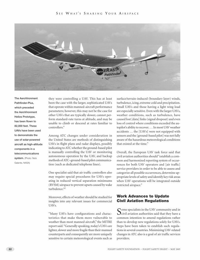
Moreover, effects of weather should be studied for insights into any relevant issues for commercial UAVs.
“Many UAVs have confi gurations and charac-teristics that make them more vulnerable to weather than most manned aircraft,” the MITRE report said. “Generally speaking, today’s UAVs are lighter, slower and more fragile than their manned counterparts and consequently are more uniquely sensitive to certain meteorological events such as
surface/terrain-induced (boundary layer) winds, turbulence, icing, extreme cold and precipitation. Small UAVs and those having a light wing load are especially sensitive. Even with the larger UAVs, weather conditions, such as turbulence, have caused lost [data] links (signal dropout) and even loss of control where conditions exceeded the au-topilot’s ability to recover. … In most UAV weather accidents … the [UAVs] were not equipped with sensors and the [ground-based pilot] was not fully aware of the hazardous meteorological conditions that existed at the time.”
Overall, the European UAV task force said that civil aviation authorities should “establish a com-mon and harmonized reporting system of occur-rences for both UAV operators and [air traffi c] service providers in order to be able to assess and categorize all possible occurrences, determine ap-propriate levels of safety and identify key risk areas when UAV operations will be integrated outside restricted airspace.”
Work Advances to UpdateCivil Aviation Regulations
Some specialists in the UAV community and in civil aviation authorities said that they have a
common intention to amend regulations rather than to develop new regulations solely for UAVs. Steps have been taken to establish such regula-tions in several countries. Minimizing UAV-related changes in ATC also is a goal of air traffi c services providers.
The AeroVironment
Pathfinder-Plus,
which preceded
the AeroVironment
Helios Prototype,
has been flown to
82,000 feet. These
UAVs have been used
to demonstrate the
use of solar-powered
aircraft as high-altitude
components in a
telecommunications
system. (Photo: Nick
Galante, NASA)
23FLIGHT SAFETY FOUNDATION • FLIGHT SAFETY DIGEST • MAY 2005
S E E W H A T ’ S S H A R I N G Y O U R A I R S P A C E
“Regulation of UAVs [by FAA] is important be-cause it will provide a legal basis for them to oper-ate in [U.S. airspace] for the fi rst time,” said the DOD roadmap for military UAVs. “This, in turn, should lead to their acceptance by international and [non-U.S.] civil aviation authorities.”
The basic principle for international operations by UAVs comes from Article 8 of the Convention on International Civil Aviation, which in 1944 said, “No aircraft capable of being fl own with-out a pilot shall be fl own over the territory of a contracting state without special authorization by that state and in accordance with the terms of such an authorization. Each contracting state undertakes to insure that the fl ight of such an aircraft without a pilot in regions open to civil aircraft shall be so controlled as to obviate danger to civil aircraft.”63
The Civil Aviation Safety Authority (CASA) in Australia said that it implemented in 2002 the world’s fi rst comprehensive civil aviation regula-tions for UAVs. In April 2005, CASA launched a project to refi ne the regulations implemented in 2002 to address airworthiness requirements for Australian UAVs, including design, manufacture and continuing airworthiness. Other civil avia-tion authorities also have ordered development of required UAV operational concepts, policies, standards, regulations and guidance.
Current Australian regulations exempt the small-est UAVs (called “micro UAVs,” with gross weight of 100.0 grams [3.5 ounces] or less) from most of the requirements applicable to large UAVs but operators must comply with rules on hazardous operation, fl ight in controlled airspace and fl ight exceeding an altitude of 400 feet above ground level. Large UAVs in Australia include unmanned airships with an envelope capacity greater than 100 cubic meters (3,531 cubic feet), unmanned powered parachutes or UAVs with a gross weight greater than 150 kilograms (331 pounds), and un-manned rotorcraft or powered lift devices with a gross weight greater than 100 kilograms (220 pounds). The large UAVs generally are treated as conventional aircraft in Australian operating rules, requiring a special certifi cate of airworthiness (re-stricted category) or an experimental certifi cate.
Small UAVs are those that do not fi t into the other categories; they can be authorized to fl y
outside an approved area if they are operated clear of populous areas and clear of controlled airspace in Australia; approval by CASA is required for fl ight at altitudes more than 400 feet above ground level.64
Requirements for fl ights by large UAVs are the most extensive, requiring fl ight under the con-trol of a certifi ed ground-based pilot (offi cially called a “UAV controller”) and CASA approval of the operation or series of operations along with certifi cation of the UAV operator, and compli-ance with rules for maintenance; radiotelephony; ATC procedures, clearances and instructions; and operational and equipment specifi cations for the class of airspace.
In 2004, Italy passed legislation authorizing the National Civil Aviation Authority, in concert with Air Navigation Services Co., to de-velop regulations enabling Italian military UAVs to operate routinely in restricted areas and corridors of civil airspace under civilian air traffi c control, news reports said.65
U.K. CAA said, “Currently, an equivalent level of [UAV] safety to that required for ‘manned fl ying’ is achieved by both appropriate regulation and restricting peace-time military UAV operations to segregated airspace (i.e., danger areas). Further, there are currently no national procedures which permit either civil [UAVs] or military [UAVs] to routinely fl y in nonsegregated airspace. … A signifi cant increase in both civil and military [UAV] fl ying is anticipated, most of which will require access to all classes of airspace if it is to be both operationally effective and/or commer-cially viable. To achieve this, [UAVs] will have to be able to meet all existing safety standards, applicable to equivalent manned aircraft types, appropriate to the class (or classes) of airspace within which they are intended to be operated. … To ensure that air traffi c controllers are aware that a fl ight is a UAV fl ight, all UAV call signs shall include the word ‘unmanned.’ … There are currently no regulations governing the qualifi ca-tions required to operate a civil registered UAV in U.K. airspace.”66

24 FLIGHT SAFETY FOUNDATION • FLIGHT SAFETY DIGEST • MAY 2005
S E E W H A T ’ S S H A R I N G Y O U R A I R S P A C E
U.K. CAA guidance includes the following general principles for UAV operation out-side of danger areas — which are depicted on CAA charts as permanent/temporary airspace to be avoided by pilots based on current NOTAMs when the area is acti-vated — in U.K. airspace:
• The ground-based pilot continuously must monitor UAV performance and ATC communications, must comply with ATC instructions and must be capable of taking immediate active control of the UAV at all times;
• The UAV must be equipped, as a mini-mum, with the same types of equip-ment required for manned aircraft in the class of airspace to be used and an approved method of preventing midair collisions (the method might include “a combination of radar cover-age and a chase aircraft or an approved on-board system”);
• The UAV must be equipped with an approved method of assuring terrain clearance; and,
• The ground-based pilot must com-ply with the visual/instrument flight rules applicable to manned aircraft. “Thus, UAVs fitted with nonvisual collision-avoidance systems must still comply with the IFR when [in in-strument meteorological conditions (IMC)] (i.e., they may not fly VFR in IMC just because they can ‘sense’ and avoid; quadrantal/semi-circular rules [for selecting altitudes based on course] will continue to apply.”
In Europe, the 2002 European Commission regulation and implement-ing rules that established the European Aviation Safety Agency (EASA) will require some UAVs to have an EASA airworthiness certifi cate (i.e., those that are neither experimental nor military and weigh more than 150 kilograms).67
In the United States, the qualifi cations for ground-based pilots have been set
by DOD and the Defense Management Contract Agency. UAVs may be operated only by DOD’s civilian contractors out-side of restricted areas or warning areas when a written agreement with FAA au-thorizes the operations. Ground-based pilots conducting such operations must have a least a private pilot certifi cate, an instrument rating, a current annual instrument review, 300 fl ight hours as pi-lot-in-command or mission commander (of UAVs or aircraft, including 100 fl ight hours in a manned aircraft), hold current ground-based pilot certifi cations (when FAA begins to require ground-based pilot certifi cation) and comply with guidance from the military service about ground-based pilot qualifi cation and currency if these requirements are more restrictive than the Defense Contract Management Agency’s requirements.68
Other countries, including the Netherlands and Sweden, have emphasized in their UAV airworthiness-certifi cation processes that UAVs should be considered as systems rather than as isolated aircraft, so that ad-equate consideration can be given to the ground control station, data link systems, systems for autonomous fl ight and colli-sion avoidance, and related software, the MITRE report said.
“Approvals for [UAV] fl ight testing and operation have already been granted for some civil projects,” said guidance ma-terial prepared by the Swedish Aviation Safety Authority. “Applications for military UAVs to be permitted to fl y in airspace where civil aviation occurs are expected shortly. … Special (occasional) solutions to compensate for faults or un-certainty in a UAV system may in some cases be necessary. A manned escort plane can be such a solution when the need to see other aircraft is essential and cannot be fulfi lled. … Until suffi cient positive experience of a UAV system has been ac-quired, special air traffi c controllers could be [provided to separate] UAVs from other traffi c within controlled airspace and to coordinate UAV fl ight paths with other air traffi c services units.”69
Innovations Could Benefi t All Civil Airspace Users
How other airspace users will infl uence proposals for integrating UAVs into
civil airspace is not clear, although many already participate in the dozens of work-ing groups established by the worldwide UAV community. Other airspace users — and society as a whole — are expected to look at the broad context of security re-quirements and the indirect benefi ts pro-vided by UAVs to the rest of the aviation community. Concerns could be allayed not only by addressing safety issues, but by introducing communication methods, collision-avoidance systems, worldwide data networks, unconventional fuels and autonomous-control capabilities that have collateral applications to manned aircraft.70
Accuracy, objectivity and data-driven methods will be required to demonstrate to aviation safety professionals that safety issues are addressed adequately in the context of UAV applications and busi-ness opportunities. Flying UAVs in civil airspace of the 21st century recalls risks of aviation in the early 20th century. ■
Notes
1. European Organization for the Safety of Air Navigation (Eurocontrol); European Joint Aviation Authorities (JAA). Joint Initiative on UAVs. A Concept for European Regulations for Civil Unmanned Aerial Vehicles (UAVs). UAV Task-Force Final Report. May 11, 2004. Lt. Col. Trond Bakken, chairman of the Eurocontrol UAV–Operational Air Traffi c (OAT) Task Force, said that the current task force was created in April 2004 for an 18-month initiative to develop voluntary Eurocontrol specifi cations for the use of military UAVs as operational air traffi c outside segregated airspace. “In the longer term, the UAV–OAT Task Force also will examine the harmonization of UAV operations in seg-regated airspace in Europe,” Bakken said. “The task force is now engaged in drafting the air traffi c management specifi cations for initial submission to the Eurocontrol

25FLIGHT SAFETY FOUNDATION • FLIGHT SAFETY DIGEST • MAY 2005
S E E W H A T ’ S S H A R I N G Y O U R A I R S P A C E
Military Team in 2005. In parallel, consul-tations between different internal divisions are taking place discussing regulatory, safety, legal, airspace and navigational is-sues.” <www.eurocontrol.int>
2. Pickup, Sharon; Sullivan, Michael J. “Unmanned Aerial Vehicles: Improved Strategic Acquisition Planning Can Help Address Emerging Challenges.” Testimony before the Subcommittee on Tactical Air and Land Forces, Committee on Armed Services, U.S. House of Representatives. U.S. Government Accountability Offi ce (GAO). GAO–05–395T. March 9, 2005. The document said, “DOD defi nes a UAV as a powered aerial vehicle that does not carry a human operator; can be land-, air- or ship-launched; uses aerodynamic forces to provide lift; can be autonomously or remotely piloted; can be expendable or recoverable; and can carry a lethal or nonlethal payload.”
3. Ibid.
4. DeGarmo, Matthew; Nelson, Gregory T. Prospective Unmanned Aerial Vehicle Operations in the Future National Airspace System. The MITRE Corp. Published by American Institute of Aeronautics and Astronautics (AIAA). September 2004.
5. McCarley, Jason S.; Wickens, Christopher D. “Human Factors Concerns in UAV Flight.” Institute of Aviation, Aviation Human Factors Division, University of Illinois at Urbana-Champaign.
6. Blakey, Marion C. Speech to RTCA Annual Forum, Washington, D.C., U.S. March 15, 2005. <www.faa.gov>
7. Eurocontrol and JAA.
8. DeGarmo, Matthew T. Issues Concerning Integration of Unmanned Aerial Vehicles in Civil Airspace. Center for Advanced Aviation System Development, The MITRE Corp. Report no. MP 04W0000323. November 2004.
9. Offi ce of the Secretary of Defense, U.S. Department of Defense (DOD). Airspace Integration Plan for Unmanned Aviation — November 2004. November 2004.
10. The Boeing Co. “Two Boeing X-45A Unmanned Jets Continue Coordinated Flights.” News release Dec. 10, 2004. The Joint Unmanned Combat Air Systems X-45 program is a program of the U.S. Defense Advanced Research Projects Agency, the U.S. Air Force, the U.S. Navy and Boeing to demonstrate the technical
feasibility, military utility and operational value of an unmanned air combat system for the Air Force and the Navy.
11. U.S. National Aeronautics and Space Administration (NASA). “NASA Flight Tests Validate UAV Collision-avoidance Technologies.” News release 02-15. March 19, 2002. The tests were conducted under the Environmental Research Aircraft and Sensor Technology (ERAST) program of NASA.
12. NASA. “Researchers Encouraged by Collision-avoidance Test Results.” News re-lease no. 03-21. April 8, 2003. The tests were conducted near Mojave, California, U.S.
13. NASA. “New Software Allows UAVs to Team Up for Virtual Experiments.” News release no. 05-18AR. March 18, 2005. The UAVs were fl own over a remote area of Edwards Air Force Base, California.
14. O’Sullivan, Arieh. “Israeli-made UAVs Helping in India.” The Jerusalem Post online edition. <www.jpost.com> Jan. 5, 2005.
15. Northrop Grumman Corp. “Northrop Grumman Unmanned Systems Employed by Department of Homeland Security for Border Patrol Missions.” News release. Nov. 18, 2004.
16. Israel Aircraft Industries. “IAI/Malat’s Bird Eye 500 Mini UAV Makes Successful Historic Maiden Voyage Over Amsterdam, Netherlands.” News release. June 20, 2004. Approval for the fl ight was received from Dutch aviation authorities after the UAV’s safety and reliability were checked during demonstration fl ights over the southern part of the country.
17. Baker, Shanna. “Not Your Ordinary Remote-controlled Airplane.” The Lookout. Canadian Forces Experimentation Centre. July 2003.
18. Herwitz, Stanley R.; Johnson, Lee F.; Dunagan, Stephen E.; Brass, James A.; Witt, Glen. “Orchestrating a Near-real-time Imaging Mission in National Airspace Using a Solar-powered UAV.” Paper presented at the Second AIAA UAV Conference, Sept. 15–18, 2003. San Diego, California, U.S.
19. Baker, Sue. “FAA Approves Global Hawk Flights in National Airspace.” U.S. Air Force Materiel Command news release no. 0839. Aug. 21, 2003.
20. Offi ce of the Secretary of Defense, DOD. Unmanned Aerial Vehicle Reliability Study. February 2003. Unmanned Aerial Vehicles
Roadmap 2002–2027. December 2002. This is the second DOD roadmap; a third revi-sion titled OSD Unmanned Aircraft Systems Roadmap was scheduled to be published in May 2005.
21. Tactical Aerospace Group. “UAV Helicopter Provides Surveillance Over the Oscars.” News release. March 2, 2005. The company said that security offi cials used a UAV to provide a roving/stationary air-borne video camera with real-time video downlink to a wide-area video distribu-tion network watched by local, state and federal commanders. Offi cials on the scene were able to monitor the video feed from the UAV using portable handheld comput-ers.
22. Sato, Akira. “Civil UAV Applications in Japan and Related Safety and Certifi cation.” Aeronautic Operations, Yamaha Motor Co. A paper presented to the European Unmanned Vehicle Systems Association’s UAVs: Concerted Actions for Regulations (UCARE) Symposium in Paris, France. June 2002.
23. Offi ce of the Secretary of Defense.
24. NASA. UAV Applications Center. <www.uav-applications.org>
25. DeGarmo. “Late in 2003, an ASTM com-mittee was formed to address certifi cation issues concerning UAV integration,” the report said. “Sense-and-avoid systems were fi rst on the agenda. In August 2004, the ASTM F38 committee on UAV standards developed its fi rst draft standard titled Standard Specifi cation for Design and Performance of an Airborne Sense-and-avoid System (designated F2411-04).”
26. DeGarmo.
27. Spalding, Travis. Public relations supervi-sor, UPS Airlines. E-mail communication with Rosenkrans, Wayne. Alexandria, Virginia, U.S. May 17, 2005. Flight Safety Foundation, Alexandria, Virginia, U.S.
28. Moiré. Cost and Business Model Analysis for Civilian UAV Missions: Final Report. Report prepared for the Suborbital Science Offi ce, Earth Science Enterprise, NASA. June 8, 2004. <www.nasa.gov>
29. General Atomics Aeronautical Systems. “General Atomics Aeronautical Systems Joins With NOAA and NASA to Help Bridge the Gap Between Earth and Science; Altair Demonstration Marks Launch of First NOAA-funded UAV Earth Science Mission.” News release. April 20,
26 FLIGHT SAFETY FOUNDATION • FLIGHT SAFETY DIGEST • MAY 2005
S E E W H A T ’ S S H A R I N G Y O U R A I R S P A C E
2005. “UAV Flight Demonstration Project — Spring 2005.” <uav.noaa.gov>
30. Christoff, Joseph A. “Nonproliferation: Improvements Needed for Controls on Exports of Cruise Missile and Unmanned Aerial Vehicle Technology.” U.S. General Accounting Offi ce. Testimony before the Subcommittee on National Security, Emerging Threats and International Relations, Committee on Government Reform, U.S. House of Representatives. March 9, 2004.
31. Offi ce of the Secretary of Defense.
32. Ibid.
33. Ebdon, Derek; Regan, John. Sense-and-avoid Requirement for Remotely Operated Aircraft (ROA). U.S. Air Force Air Combat Command White Paper. June 25, 2004.
34. Offi ce of the Secretary of Defense.
35. Drumm, A.C.; Andrews, J.W.; Hall, T.D.; Heinz, V.M.; Kuchar, J.K.; Thompson, S.D.; Welch, J.D. “Remotely Piloted Vehicles in Civil Airspace: Requirements and Analysis Methods for the Traffi c Alert and Collision Avoidance System (TCAS) and See-and-avoid Systems.” Paper presented to the 23rd Digital Avionics Systems Conference, Salt Lake City, Utah, U.S. Oct. 24–28, 2004. The authors are conducting research at the Massachusetts (U.S.) Institute of Technology (MIT) Lincoln Laboratory under contract to the U.S. Air Force.
36. Ibid.
37. Kuchar, James; Andrews, John; Drumm, Ann; Hall, Tim; Heinz, Val; Thompson, Steven; Welch, Jerry. “A Safety Analysis Process for the Traffi c Alert and Collision Avoidance System (TCAS) and See-and-avoid Systems on Remotely Piloted Vehicles.” Paper presented to the AIAA Unmanned Unlimited Technical Conference, Chicago, Illinois, U.S. Sept. 20–23, 2004.
38. Drumm et al. Working Group 2 of the ICAO Secondary Surveillance Radar Improvements and Collision Avoidance Systems Panel (SICASP) in 2002 published a report about TCAS on UAVs; this work currently is being used by MIT Lincoln Laboratory researchers. Working Group A of the same panel, renamed ICAO Surveillance and Confl ict Resolution Systems Panel (SCRSP), met in 2004.
39. Kuchar et al.
40. Drumm et al.
41. Directorate of Airspace Policy, U.K. Civil Aviation Authority. Unmanned Aerial Vehicle Operations in UK Airspace — Guidance. Civil Aeronautics Publication (CAP) 722. Second edition, Nov. 12, 2004.
42. Ebdon and Regan.
43. Offi ce of the Secretary of Defense.
44. Ibid.
45. Sabatini, Nick. Prepared remarks for RTCA Special Committee 203. Nov. 30, 2004.
46. Swartz, Steve. “Did You See the UAV?” FAA Aviation News. March–April 2005.
47. Offi ce of the Secretary of Defense. Airspace Integration Plan for Unmanned Aviation — December 2004.
48. Weibel, Roland E.; Hansman Jr., R. John. Safety Considerations for Operation of Different Classes of UAVs in the NAS. Sept. 20, 2004.
49. Weibel and Hansman.
50. Systems Engineering and Integration Team, Access 5. In the United States, high-altitude, long-endurance UAVs include AeroVironment’s Pathfi nder-Plus and Helios, General Atomics Aeronautical Systems’ Predator B and Altair, Northrop Grumman’s Global Hawk and Aurora Flight Sciences’ Perseus B. “Pathfi nder-Plus and Helios are solar-powered [UAVs] that have very limited maneuvering capability,” said the Access 5 report. “Both climb and turn slowly, and their cruise speed generally does not exceed [43 knots]. The Perseus B cruises at 65 knots up to an altitude of 60,000 feet. The Predator B and Altair HALE [UAVs’] maneuvering capabilities are similar to a manned aircraft, yet their climb speed and cruise speed (200-knot range) still are con-siderably slower than the majority of other aircraft that operate at their altitude. Global Hawk’s climb and cruise speeds are more similar to those of commercial jet aircraft that operate in the same airspace.”
51. Systems Engineering and Integration Team, Access 5. HALE ROA [High-alti-tude Long-endurance Remotely Operated Aircraft] Concept of Operations. Version 2.0, March 2005.
52. Offi ce of the Secretary of Defense. Airspace Integration Plan for Unmanned Aviation — 2004.
53. Ibid.
54. Airservices Australia. Notice to airmen. Briefi ng reference no. 133448. April 13, 2005.
55. Williams, Kevin W. A Summary of Unmanned Aircraft Accident/Incident Data: Human Factors Implications. Civil Aerospace Medical Institute, FAA. Final Report no. DOT/FAA/AM-04/24. December 2004.
56. In DOD terminology, Class A mishaps are aircraft accidents resulting in loss of the aircraft or loss of human life, or causing more than US$1 million in damage.
57. Offi ce of the Secretary of Defense. Unmanned Aerial Vehicles Roadmap 2002–2027.
58. Ibid.
59. Offi ce of the Secretary of Defense. Unmanned Aerial Vehicle Reliability Study. February 2003.
60. Ibid.
61. Williams.
62. DeGarmo.
63. U.K. CAA. CAP 722.
64. Civil Aviation Safety Authority, Australia. “Certifi cation Requirements Related to the Design, Manufacturing and Airworthiness of UAVs.” April 11, 2005. Staff writers; Blackman, Sherridan. “Attack of the Drones.” Flight Safety Australia. December 2002.
65. Kington, Tom. “Italy Could Fly UAVs in Civil Air by Year End.” <www.c4isrjournal.com> June 14, 2004. UVOnline. “Italian Parliament Approves Law on UAV Deployment.” <www.uvonline.com> July 2004. DeGarmo and Nelson.
66. U.K. CAA. CAP 722.
67. Ibid.
68. Offi ce of the Secretary of Defense. Airspace Integration Plan for Unmanned Aviation — November 2004.
69. Wiklund, Eskil. Swedish Aviation Safety Authority. Flying With Unmanned Aircraft (UAVs) in Airspace Involving Civil Aviation Activity — Air Safety and the Approvals Procedure. March 25, 2003.
70. DeGarmo.

27FLIGHT SAFETY FOUNDATION • FLIGHT SAFETY DIGEST • MAY 2005
Although the number of accidents in-volving large Western-built commercial jets operated by International Air Transport Association (IATA)-member
airlines and non-IATA-member airlines increased from 99 in 2003 to 103 in 2004,1 the number of fatalities in 2004 declined to 428, compared with 663 in 2003. In 2002, 974 people were killed during fl ight operations.2
The industrywide hull-loss accident3 rate declined 10 percent in 2004, to 0.78 hull losses per million departures, IATA said (Figure 1, page 28).
Giovanni Bisignani, IATA director general and CEO, said, “2004 was the safest year ever for air transport.”
Preliminary reports of the number of fatal airline accidents worldwide in 2004, including accidents involving non-Western aircraft, ranged from 26 to 28.4
Commercial jets were involved in three controlled-fl ight-into-terrain (CFIT) accidents in 2004, with
42 total fatalities. (One CFIT accident was a posi-tioning fl ight for an on-demand [air taxi] opera-tion.) That compared with seven CFIT accidents in 2003, resulting in 203 total fatalities, and fi ve CFIT accidents in 2002, with 357 total fatalities.5
In 2004, more than 1.8 billion passengers traveled in commercial aircraft worldwide.6
Other preliminary data for 2004, published by the U.S. National Transportation Safety Board (NTSB), showed that the number of accidents7 and the ac-cident rates for U.S. air carriers operating under U.S. Federal Aviation Regulations (FARs) Part 121, Domestic, fl ag and supplemental operations, declined in 2004 compared with 2003 (Table 1, page 29). The number of fatal accidents8 and the rates of fatal ac-cidents per 100,000 fl ight hours and fatal accidents per 100,000 departures were identical to those of the previous year.
There were no fatal accidents in 2004 involving scheduled (commuter) operations under FARs Part 135, Operating requirements: Commuter and on demand operations and rules governing
AVIATION STATISTICS
2004 Was ‘Safest Year Ever’For Air TransportDespite an increase in passenger traffic, there were fewer fatalities worldwide in 2004 involving
large Western-built commercial jets than in each of the previous two years. The number of
accidents and the rates of accidents declined for air carriers flying under U.S. Federal Aviation
Regulations Part 121, and there were no fatal accidents for scheduled flights under Part 135.
— FSF EDITORIAL STAFF

FLIGHT SAFETY FOUNDATION • FLIGHT SAFETY DIGEST • MAY 200528
S T A T I S T I C S
persons on board such aircraft. The fatal-accident rate for Part 135 on-demand operations per 100,000 fl ight hours was higher than the rate for scheduled Part 121 operations.
NTSB said that 28 total accidents and two fatal accidents occurred involving Part 121 air carriers, compared with 54 total accidents and two fatal accidents in 2003.
[The two fatal Part 121 accidents in 2004 included a British Aerospace (BAe) Jetstream 32 that struck terrain during an instrument approach to Kirksville (Missouri, U.S.) Regional Airport on Oct. 19, with 13 fatalities, and a Convair 580 that struck terrain during a visual ap-proach to Cincinnati/Northern Kentucky (U.S.) International Airport on Aug. 13,
with one fatality. The Aug. 13 accident was a nonscheduled Part 121 cargo fl ight. Both accidents remain under investigation.]
Part 121 scheduled operations in 2004 had a lower accident rate, with 0.124 accidents per 100,000 flight hours and 0.199 accidents per 100,000 departures, than scheduled operations under Part 135, which had 1.515 accidents per 100,000 flight hours and 0.843 acci-dents per 100,000 departures, NTSB said (Table 2, page 30). The fatal- accident rate was 0.006 accidents per 100,000 flight hours and 0.009 accidents per 100,000 departures for Part 121 sched-uled operations. Part 135 on-demand operations had a fatal- accident rate of 0.780 per 100,000 flight hours; the fatal- accident rate based on departures was not available.
There were 11 passenger fatalities and three passenger serious injuries9 in Part 121 accidents in 2004 — equivalent to 56.5 million enplanements per passenger fatality and 207 million enplanements per passenger serious injury, NTSB said. Including aircraft crewmembers, there were 14 fatalities.
For Part 121 air carriers, the number and rate of major accidents10 increased in 2004 compared with the previous two years, but the numbers and rates of acci-dents classifi ed as serious accidents,11 in-jury accidents12 and damage accidents13 declined (Table 3, page 30).
Part 121 air carriers experienced three hull losses in 2004, for a rate of 0.171 per million fl ight hours (Table 4, page 31).
Figure 1
Western-built Jet Air-transport Traffic and Hull-loss Rates, 1995–2004
Note: A hull loss is defined as an accident in which an aircraft is substantially damaged and is not subsequently repaired for whatever reason, including a financial decision of the owner.
Source: International Air Transport Association
0.94
1.11
1.341.32
0.78
0.0
0.3
0.6
0.9
1.2
1.5
1.8
1995 1996 1997 1998 1999 2000 2001 2002 2003 2004
Hu
llLo
sses
per
Mill
ion
Dep
artu
res
8
12
16
20
24
Millio
ns
ofD
epartu
resFlo
wn
Hull Losses per Million Departures
Millions of Departures Flown
Year
Continued on page 31

FLIGHT SAFETY FOUNDATION • FLIGHT SAFETY DIGEST • MAY 2005 29
S T A T I S T I C S
Tab
le 1
Acc
iden
ts, F
atal
itie
s an
d A
ccid
ent
Rat
es, U
.S. A
ir C
arri
ers
Op
erat
ing
Un
der
FA
Rs
Par
t 1
21
, Sc
hed
ule
d a
nd
No
nsc
hed
ule
d S
ervi
ce (A
irlin
es),
19
85
–20
04
Year
Acc
iden
tsFa
talit
ies
Flig
ht
Ho
urs
M
iles
Flo
wn
D
epar
ture
s
Acc
iden
ts
per
10
0,0
00
Flig
ht
Ho
urs
Acc
iden
ts
per
1,0
00
,00
0 M
iles
Flo
wn
Acc
iden
ts
per
10
0,0
00
D
epar
ture
s
All
Fata
l To
tal
Ab
oar
d
All
Fata
l A
ll Fa
tal
All
Fata
l
1985
21
7
526
525
8,70
9,89
4 3,
631,
017,
000
6,30
6,75
9 0.
241
0.08
0 0.
0058
0.
0019
0.
333
0.11
1
1986
* 24
3
8 7
9,97
6,10
4 4,
017,
626,
000
7,20
2,02
7 0.
231
0.02
0 0.
0057
0.
0005
0.
319
0.02
8
1987
* 34
5
232
230
10,6
45,1
92
4,36
0,52
1,00
0 7,
601,
373
0.31
0 0.
038
0.00
76
0.00
09
0.43
4 0.
053
1988
* 30
3
285
274
11,1
40,5
48
4,50
3,42
6,00
0 7,
716,
061
0.26
0 0.
018
0.00
64
0.00
04
0.37
6 0.
026
1989
28
11
27
8 27
6 11
,274
,543
4,
605,
083,
000
7,64
5,49
4 0.
248
0.09
8 0.
0061
0.
0024
0.
366
0.14
4
1990
24
6
39
12
12,1
50,1
16
4,94
7,83
2,00
0 8,
092,
306
0.19
8 0.
049
0.00
49
0.00
12
0.29
7 0.
074
1991
26
4
62
49
11,7
80,6
10
4,82
4,82
4,00
0 7,
814,
875
0.22
1 0.
034
0.00
54
0.00
08
0.33
3 0.
051
1992
18
4
33
31
12,3
59,7
15
5,03
9,43
5,00
0 7,
880,
707
0.14
6 0.
032
0.00
36
0.00
08
0.22
8 0.
051
1993
23
1
1 0
12,7
06,2
06
5,24
9,46
9,00
0 8,
073,
173
0.18
1 0.
008
0.00
44
0.00
02
0.28
5 0.
012
1994
* 23
4
239
237
13,1
24,3
15
5,47
8,11
8,00
0 8,
238,
306
0.16
8 0.
030
0.00
40
0.00
07
0.26
7 0.
049
1995
36
3
168
162
13,5
05,2
57
5,65
4,06
9,00
0 8,
457,
465
0.26
7 0.
022
0.00
64
0.00
05
0.42
6 0.
035
1996
37
5
380
350
13,7
46,1
12
5,87
3,10
8,00
0 8,
228,
810
0.26
9 0.
036
0.00
63
0.00
09
0.45
0 0.
061
1997
49
4
8 6
15,8
38,1
09
6,69
6,63
8,00
0 10
,318
,383
0.
309
0.02
5 0.
0073
0.
0006
0.
475
0.03
9
1998
50
1
1 0
16,8
16,5
55
6,73
6,54
3,00
0 10
,979
,762
0.
297
0.00
6 0.
0074
0.
0001
0.
455
0.00
9
1999
51
2
12
11
17,5
55,2
08
7,10
1,31
4,00
0 11
,308
,762
0.
291
0.01
1 0.
0072
0.
0003
0.
451
0.01
8
2000
56
3
92
92
18,2
99,2
57
7,52
4,02
7,00
0 11
,468
,229
0.
306
0.01
6 0.
0074
0.
0004
0.
488
0.02
6
2001
* 46
6
531
525
17,8
14,1
91
7,29
4,19
1,00
0 10
,954
,832
0.
236
0.01
1 0.
0058
0.
0003
0.
383
0.01
8
2002
41
0
0 0
17,2
90,1
98
7,19
2,50
1,00
0 10
,508
,473
0.
237
—0.
0057
—
0.39
0 —
2003
54
2
22
21
17,4
33,9
64
7,28
0,38
3,00
0 10
,422
,862
0.
310
0.01
1 0.
0074
0.
0003
0.
518
0.01
9
2004
28
2
14
14
17,5
75,0
00
7,37
8,30
0,00
0 10
,785
,000
0.
159
0.01
1 0.
0038
0.
0003
0.
260
0.01
9
FARs
= U
.S. F
eder
al A
viat
ion
Reg
ula
tio
ns
No
te: 2
004
dat
a ar
e p
relim
inar
y.
Flig
ht
ho
urs
, mile
s an
d d
epar
ture
s ar
e co
mp
iled
by
the
U.S
. Fed
eral
Avi
atio
n A
dm
inis
trat
ion
.
Sin
ce M
arch
20,
199
7, a
ircr
aft
wit
h 1
0 o
r mo
re s
eats
use
d in
sch
edu
led
pas
sen
ger
ser
vice
hav
e b
een
op
erat
ed u
nd
er F
ARs
Par
t 12
1.
Year
s fo
llow
ed b
y th
e sy
mb
ol *
are
th
ose
in w
hic
h a
n il
leg
al a
ct w
as re
spo
nsi
ble
for a
n o
ccu
rren
ce in
th
is c
ateg
ory
. Th
ese
acts
, su
ch a
s su
icid
e, s
abo
tag
e an
d te
rro
rism
, are
incl
ud
ed in
th
e to
tals
for
acci
den
ts a
nd
fata
litie
s b
ut
are
excl
ud
ed fr
om
acc
iden
t ra
tes.
Oth
er t
han
th
e p
eop
le a
bo
ard
air
craf
t w
ho
wer
e ki
lled,
fata
litie
s re
sult
ing
fro
m t
he
Sep
t. 11
, 200
1, te
rro
rist
act
are
exc
lud
ed fr
om
th
is
tab
le.
Sou
rce:
U.S
. Nat
ion
al T
ran
spo
rtat
ion
Saf
ety
Bo
ard

FLIGHT SAFETY FOUNDATION • FLIGHT SAFETY DIGEST • MAY 200530
S T A T I S T I C S
Table 2
Accidents, Fatalities and Accident Rates, U.S. Aviation, 2004
Accidents Fatalities
Flight Hours Departures
Accidents per 100,000 Flight Hours
Accidents per 100,000 Departures
All Fatal Total Aboard All Fatal All Fatal
U.S. air carriers operating under FARs Part 121
Scheduled 21 1 13 13 17,000,000 10,547,000 0.124 0.006 0.199 0.009 Nonscheduled 7 1 1 1 575,000 238,000 1.217 0.174 2.941 0.420
U.S. air carriers operating under FARs Part 135
Scheduled 5 — — — 330,000 593,000 1.515 — 0.843 —Nonscheduled 68 24 65 64 3,072,000 — 2.210 0.780 — —
FARs = U.S. Federal Aviation Regulations
Note: All data are preliminary.
Flight hours and departures are compiled and estimated by the U.S. Federal Aviation Administration.
Departure information for nonscheduled FARs Part 135 operations is not available.
Source: U.S. National Transportation Safety Board
Table 3
Accidents and Accident Rates by NTSB Classification, U.S. Air Carriers Operating Under FARs Part 121, 1985–2004
Year
AccidentsFlight Hours
(millions)
Accidents per Million Flight Hours
Major Serious Injury Damage Major Serious Injury Damage
1985 8 2 5 6 8.710 0.918 0.230 0.574 0.689
1986 4 0 14 6 9.976 0.401 0.000 1.403 0.601
1987 5 1 12 16 10.645 0.470 0.094 1.127 1.503
1988 4 2 13 11 11.141 0.359 0.180 1.167 0.987
1989 8 4 6 10 11.275 0.710 0.355 0.532 0.887
1990 4 3 10 7 12.150 0.329 0.247 0.823 0.576
1991 5 2 10 9 11.781 0.424 0.170 0.849 0.764
1992 3 3 10 2 12.360 0.243 0.243 0.809 0.162
1993 1 2 12 8 12.706 0.079 0.157 0.944 0.630
1994 4 0 12 7 13.124 0.305 0.000 0.914 0.533
1995 3 2 14 17 13.505 0.222 0.148 1.037 1.259
1996 6 0 18 13 13.746 0.436 0.000 1.309 0.946
1997 2 4 24 19 15.838 0.126 0.253 1.515 1.200
1998 0 3 21 26 16.817 0.000 0.178 1.249 1.546
1999 2 2 20 27 17.555 0.114 0.114 1.139 1.538
2000 3 3 20 30 18.299 0.109 0.109 1.093 1.475
2001 5 1 19 21 17.814 0.281 0.056 1.067 1.179
2002 1 1 14 25 17.290 0.058 0.058 0.810 1.446
2003 2 3 24 25 17.434 0.115 0.172 1.377 1.434
2004 3 0 13 12 17.575 0.171 0.000 0.740 0.683
FARs = U.S. Federal Aviation Regulations NTSB = U.S. National Transportation Safety Board
Note: Since March 20, 1997, aircraft with 10 or more seats used in scheduled passenger service have been operated under FARs Part 121.
A major accident is defi ned as one in which a Part 121 aircraft was destroyed, or there were multiple fatalities or there was one fatality and a Part 121 aircraft was substantially damaged.
A serious accident is defi ned as one in which there was one fatality without substantial damage to a Part 121 aircraft or there was at least one serious injury and a Part 121 aircraft was substantially damaged.
An injury accident is defi ned as one with at least one serious injury and without substantial damage to a Part 121 aircraft.
A damage accident is defi ned as one in which no person was killed or seriously injured but in which any aircraft was substantially damaged.
Source: U.S. National Transportation Safety Board
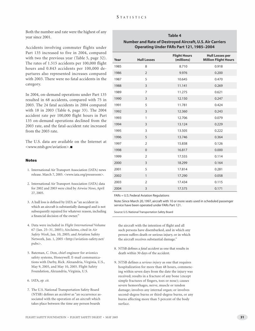
FLIGHT SAFETY FOUNDATION • FLIGHT SAFETY DIGEST • MAY 2005 31
S T A T I S T I C S
Both the number and rate were the highest of any year since 2001.
Accidents involving commuter flights under Part 135 increased to five in 2004, compared with two the previous year (Table 5, page 32). The rates of 1.515 accidents per 100,000 flight hours and 0.843 accidents per 100,000 de-partures also represented increases compared with 2003. There were no fatal accidents in the category.
In 2004, on-demand operations under Part 135 resulted in 68 accidents, compared with 75 in 2003. The 24 fatal accidents in 2004 compared with 18 in 2003 (Table 6, page 33). The 2004 accident rate per 100,000 fl ight hours in Part 135 on-demand operations declined from the 2003 rate, and the fatal-accident rate increased from the 2003 rate.
The U.S. data are available on the Internet at <www.ntsb.gov/aviation>. ■
Notes
1. International Air Transport Association (IATA) news release. March 7, 2005. <www.iata.org/pressroom>.
2. International Air Transport Association (IATA) data for 2002 and 2003 were cited by Airwise News, April 27, 2005.
3. A hull loss is defi ned by IATA as “an accident in which an aircraft is substantially damaged and is not subsequently repaired for whatever reason, including a fi nancial decision of the owner.”
4. Data were included in Flight International Volume 67 (Jan. 25–31, 2005); Airclaims, cited in Air Safety Week, Jan. 10, 2005; and Aviation Safety Network, Jan. 1, 2005 <http://aviation-safety.net/pubs>.
5. Bateman, C. Don, chief engineer for avionics safety systems, Honeywell. E-mail communica-tions with Darby, Rick. Alexandria, Virginia, U.S., May 9, 2005, and May 10, 2005. Flight Safety Foundation, Alexandria, Virginia, U.S.
6. IATA, op. cit.
7. The U.S. National Transportation Safety Board (NTSB) defi nes an accident as “an occurrence as-sociated with the operation of an aircraft which takes place between the time any person boards
the aircraft with the intention of fl ight and all such persons have disembarked, and in which any person suffers death or serious injury, or in which the aircraft receives substantial damage.”
8. NTSB defi nes a fatal accident as one that results in death within 30 days of the accident.
9. NTSB defines a serious injury as one that requires hospitalization for more than 48 hours, commenc-ing within seven days from the date the injury was received; results in a fracture of any bone (except simple fractures of fingers, toes or nose); causes severe hemorrhages, nerve, muscle or tendon damage; involves any internal organ; or involves second-degree burns or third-degree burns, or any burns affecting more than 5 percent of the body surface.
Table 4
Number and Rate of Destroyed Aircraft, U.S. Air Carriers Operating Under FARs Part 121, 1985–2004
Year Hull LossesFlight Hours
(millions)Hull Losses per
Million Flight Hours
1985 8 8.710 0.918
1986 2 9.976 0.200
1987 5 10.645 0.470
1988 3 11.141 0.269
1989 7 11.275 0.621
1990 3 12.150 0.247
1991 5 11.781 0.424
1992 3 12.360 0.243
1993 1 12.706 0.079
1994 3 13.124 0.229
1995 3 13.505 0.222
1996 5 13.746 0.364
1997 2 15.838 0.126
1998 0 16.817 0.000
1999 2 17.555 0.114
2000 3 18.299 0.164
2001 5 17.814 0.281
2002 1 17.290 0.058
2003 2 17.434 0.115
2004 3 17.575 0.171
FARs = U.S. Federal Aviation Regulations
Note: Since March 20, 1997, aircraft with 10 or more seats used in scheduled passenger service have been operated under FARs Part 121.
Source: U.S. National Transportation Safety Board

FLIGHT SAFETY FOUNDATION • FLIGHT SAFETY DIGEST • MAY 200532
S T A T I S T I C S
Tab
le 5
Acc
iden
ts, F
atal
itie
s an
d A
ccid
ent
Rat
es, U
.S. A
ir C
arri
ers
Op
erat
ing
Un
der
FA
Rs
Par
t 1
35
, Sch
edu
led
Ser
vice
, 19
85
–20
04
Year
Acc
iden
tsFa
talit
ies
Flig
ht
Ho
urs
M
iles
Flo
wn
D
epar
ture
s
Acc
iden
ts
per
10
0,0
00
Fl
igh
t H
ou
rs
Acc
iden
ts
per
1,0
00
,00
0
Mile
s Fl
ow
n
Acc
iden
ts p
er
10
0,0
00
Dep
artu
res
All
Fat
al
To
tal
Ab
oar
d
All
Fat
al
All
Fat
al
All
Fat
al
1985
187
3736
1,73
7,10
630
0,81
7,00
02,
561,
463
1.03
60.
403
0.05
980.
0233
0.70
30.
273
1986
142
44
1,72
4,58
630
7,39
3,00
02,
798,
811
0.81
20.
116
0.04
550.
0065
0.50
00.
071
1987
3310
5957
1,94
6,34
935
0,87
9,00
02,
809,
918
1.69
50.
514
0.09
400.
0285
1.17
40.
356
1988
182
2121
2,09
2,68
938
0,23
7,00
02,
909,
005
0.86
00.
096
0.04
730.
0053
0.61
90.
069
1989
195
3131
2,24
0,55
539
3,61
9,00
02,
818,
520
0.84
80.
223
0.04
830.
0127
0.67
40.
177
1990
153
64
2,34
1,76
045
0,13
3,00
03,
160,
089
0.64
10.
128
0.03
330.
0067
0.47
50.
095
1991
238
9977
2,29
1,58
143
3,90
0,00
02,
820,
440
1.00
40.
349
0.05
300.
0184
0.81
50.
284
1992
*23
721
212,
335,
349
507,
985,
000
3,11
4,93
20.
942
0.30
00.
0433
0.01
380.
706
0.22
5
1993
164
2423
2,63
8,34
755
4,54
9,00
03,
601,
902
0.60
60.
152
0.02
890.
0072
0.44
40.
111
1994
103
2525
2,78
4,12
959
4,13
4,00
03,
581,
189
0.35
90.
108
0.01
680.
0050
0.27
90.
084
1995
122
99
2,62
7,86
655
0,37
7,00
03,
220,
262
0.45
70.
076
0.02
180.
0036
0.37
30.
062
1996
111
1412
2,75
6,75
559
0,72
7,00
03,
515,
040
0.39
90.
036
0.01
860.
0017
0.31
30.
028
1997
165
4646
982,
764
246,
029,
000
1,39
4,09
61.
628
0.50
90.
0650
0.02
031.
148
0.35
9
1998
80
00
353,
670
50,7
73,0
0070
7,07
12.
262
—0.
1576
—1.
131
—
1999
135
1212
342,
731
52,4
03,0
0067
2,27
83.
793
1.45
90.
2481
0.09
541.
934
0.74
4
2000
121
55
369,
535
44,9
43,0
0060
3,65
93.
247
0.27
10.
2670
0.02
231.
988
0.16
6
2001
72
1313
300,
432
43,0
99,0
0055
8,05
22.
330
0.66
60.
1624
0.04
641.
254
0.35
8
2002
70
00
273,
559
41,6
33,0
0051
3,45
22.
559
—
0.16
81 —
1.36
3 —
2003
21
22
319,
206
47,4
04,0
0058
0,80
50.
627
0.31
30.
0422
0.02
110.
344
0.17
2
2004
50
00
330,
000
51,1
00,0
0059
3,00
01.
515
—
0.09
78 —
0.
843
—
FARs
= U
.S. F
eder
al A
viat
ion
Reg
ula
tio
ns
No
te: 2
004
dat
a ar
e p
relim
inar
y.
Flig
ht
ho
urs
, mile
s an
d d
epar
ture
s ar
e co
mp
iled
by
the
U.S
. Fed
eral
Avi
atio
n A
dm
inis
trat
ion
(FA
A).
Sin
ce M
arch
20,
199
7, a
ircr
aft
wit
h 1
0 o
r mo
re s
eats
use
d in
sch
edu
led
pas
sen
ger
ser
vice
hav
e b
een
op
erat
ed u
nd
er F
ARs
Par
t 12
1.
Year
s fo
llow
ed b
y th
e sy
mb
ol *
are
th
ose
in w
hic
h a
n il
leg
al a
ct w
as re
spo
nsi
ble
for a
n o
ccu
rren
ce in
th
is c
ateg
ory
. Th
ese
acts
, su
ch a
s su
icid
e, s
abo
tag
e an
d te
rro
rism
, are
incl
ud
ed in
th
e to
tals
for
acci
den
ts a
nd
fata
litie
s b
ut
are
excl
ud
ed fr
om
acc
iden
t ra
tes.
Bas
ed o
n a
Feb
ruar
y 20
02 F
AA
leg
al in
terp
reta
tio
n p
rovi
ded
to t
he
U.S
. Nat
ion
al T
ran
spo
rtat
ion
Saf
ety
Bo
ard
(NTS
B),
any
FARs
Par
t 13
5 o
per
atio
n c
on
du
cted
wit
h n
o re
ven
ue
pas
sen
ger
s ab
oar
d is
co
nsi
der
ed a
no
nsc
hed
ule
d fl
igh
t o
per
atio
n. T
his
inte
rpre
tati
on
has
bee
n a
pp
lied
to a
ccid
ents
beg
inn
ing
in t
he
year
200
2. It
has
no
t b
een
ap
plie
d re
tro
acti
vely
to 3
6 ac
cid
ents
, nin
e o
f th
em fa
tal,
that
occ
urr
ed d
uri
ng
th
e p
erio
d 1
983–
2001
.
Sou
rce:
U.S
. Nat
ion
al T
ran
spo
rtat
ion
Saf
ety
Bo
ard

FLIGHT SAFETY FOUNDATION • FLIGHT SAFETY DIGEST • MAY 2005 33
S T A T I S T I C S
Table 6
Accidents, Fatalities and Accident Rates, U.S. Air Carriers Operating Under FARs Part 135, Nonscheduled Service, 1985–2004
Year
Accidents Fatalities
Flight Hours
Accidents per 100,000 Flight Hours
All Fatal Total Aboard All Fatal
1985 157 35 76 75 2,570,000 6.11 1.36
1986 118 31 65 61 2,690,000 4.39 1.15
1987 96 30 65 63 2,657,000 3.61 1.13
1988 102 28 59 55 2,632,000 3.88 1.06
1989 110 25 83 81 3,020,000 3.64 0.83
1990 107 29 51 49 2,249,000 4.76 1.29
1991 88 28 78 74 2,241,000 3.93 1.25
1992 76 24 68 65 2,844,000 2.67 0.84
1993 69 19 42 42 2,324,000 2.97 0.82
1994 85 26 63 62 2,465,000 3.45 1.05
1995 75 24 52 52 2,486,000 3.02 0.97
1996 90 29 63 63 3,220,000 2.80 0.90
1997 82 15 39 39 3,098,000 2.65 0.48
1998 77 17 45 41 3,802,000 2.03 0.45
1999 74 12 38 38 3,204,000 2.31 0.37
2000 80 22 71 68 3,930,000 2.04 0.56
2001 72 18 60 59 2,997,000 2.40 0.60
2002 60 18 35 35 2,911,000 2.06 0.62
2003 75 18 42 40 2,927,000 2.56 0.61
2004 68 24 65 64 3,072,000 2.21 0.78
FARs = U.S. Federal Aviation Regulations
Note: 2004 data are preliminary.
Flight hours are estimated by the U.S. Federal Aviation Administration (FAA). Miles fl own and departure information for nonscheduled Part 135 operations are not available.
In 2002, FAA changed its estimate of nonscheduled (on-demand) activity. The revision was applied retroactively, beginning with the year 1992. In 2003, FAA again revised fl ight-activity estimates for 1999 to 2002.
Source: U.S. National Transportation Safety Board
10. NTSB classifi es as a major accident one in which a U.S. Federal Aviation Regulations (FARs) Part 121 aircraft was destroyed, or there were multiple fatali-ties or there was one fatality and a Part 121 aircraft was substantially damaged.
11. NTSB classifi es as a serious accident one in which there was one fatality without substantial damage to a Part 121 aircraft or there was at least one serious injury and a Part 121 aircraft was substantially damaged.
12. NTSB classifies as an injury accident a nonfatal ac-cident with at least one serious injury and without substantial damage to a Part 121 aircraft.
13. NTSB classifies as a damage accident an accident in which no person was killed or seriously injured, but in which any aircraft was substantially dam-aged. organ; or involves second-degree burns or third-degree burns, or any burns affecting more than 5 percent of the body surface.

34 FLIGHT SAFETY FOUNDATION • FLIGHT SAFETY DIGEST • MAY 2005
PUBLICATIONS RECEIVED AT FSF JERRY LEDERER
AVIATION SAFETY LIBRARY
‘Root Causes’ in the SystemCan Underlie Human ErrorOperational human error in accidents is often only the final manifestation of ‘latent’
human error in management, design and maintenance. An open organizational culture
and user-centered design are said to be among the ways to minimize human error.
— FSF LIBRARY STAFF
Books
The Blame Machine: Why Human Error Causes Accidents. Whittingham, R.B. Oxford, England: Elsevier Butterworth-Heinemann, 2004. 288 pp. Figures, tables, appendix, references, index.
“In the immediate aftermath of a serious ac-cident, there is a natural tendency, especially
by the media, quickly to suggest a cause and maybe attribute blame,” says the author. “Quite often the words ‘it is believed the accident was a result of human error’ are heard. There is an air of fi nality about this statement, it being implicit that no more can be said or done. The inevitable has happened. [It is hoped that] the accident investigation which is held later does not accept human error as inevi-table, but goes on to reveal the underlying reasons why the error occurred.”
The book focuses on system faults that can make errors more likely, the author says. Part I classifi es types of errors and suggests ways of estimating their frequency, so that their frequency can be minimized. Part II comprises studies of serious accidents in various industries, including aviation, to show how systemic errors were implicated.
“The direct cause [of the accidents discussed] is usually a human error, while the root cause tends to be the main underlying system fault that made the error possible or more likely,” says the author. “The contributory causes are less signifi cant factors or systems that also infl uenced the probability of error. The system of interest may be an item of equipment, a procedure or an organizational system.”
Although some instances of human error are “active” — occurring in operations — many are “latent,” the author says. Types of latent errors that he discusses in connection with pertinent acci-dents include organizational and management errors, design errors and maintenance errors.
Among the factors that can minimize human error that is encouraged by systemic failure, the author says, are the following:
• An open organizational culture that ac-knowledges mistakes and learns from them, emphasizing underlying causes more than individual actions; and,
• User-centered design, in which “the design of the system is matched as closely as possible
FLIGHT SAFETY FOUNDATION • FLIGHT SAFETY DIGEST • MAY 2005 35
R E S O U R C E S
to human capabilities and limitations.” This is contrasted with system-centered design, in which the system rather than the human operating it is the focus of attention. The author says, “There are numerous examples of complex technological systems that have been designed mainly with system func-tionality in mind, ignoring the capabilities and limitations of the user. Such systems invariably result in degraded levels of hu-man performance, with grave consequences for productivity, equipment availability and safety.”
The Wright Brothers Legacy: Orville and Wilbur Wright and Their Aeroplanes. Burton, Walt; Findsen, Owen. New York, New York, U.S.: Harry N. Abrams, 2003. 224 pp. Photographs.
“An important aspect of the Wright Brothers’ quest to fl y was their use of photography,
because it provided irrefutable evidence that on that cold and barren stretch of beach [at Kitty Hawk, North Carolina, U.S.] they had succeeded,” says Alexander Lee Nyerges, director and CEO of the Dayton [Ohio, U.S.] Art Institute, in his foreword. “It is quite fi tting that the Wrights had the foresight to employ photography in their endeavors. … Not only did they use pho-tography as a documentary tool, but they took great pains to ensure that it was dramatic and aesthetically powerful. The beauty and majesty of the ‘fi rst fl ight’ photograph is not the result of good fortune alone. The Wrights planned to capture that fl eeting moment on fi lm. And they were successful.”
The book was published in connection with an exhibition at the Dayton Art Institute, of which Orville Wright was a founding trustee. It includes photographs — black-and-white, sepia and hand-tinted — by, and of, the Wright broth-ers. Wright-related material, including postcards, news photographs, magazine covers and souvenirs, also is represented.
“Starting about 1898, Wilbur and Orville pur-chased a four[-inch] by fi ve[-inch] [10-centimeter by 13-centimeter] glass-plate camera and built a darkroom in a shed in their backyard,” say the au-thors. “It began as another of their many hobbies, but when they began fl ying gliders at Kitty Hawk in 1900, their photographs served as a visual record
of their fl ying experiments. … Between 1900 and 1906, they made hundreds of pictures of gliders and airplanes in fl ight, including their famous im-age, taken Dec. 17, 1903, of the fi rst moment that man left the ground in a heavier-than-air, powered fl ying machine.”
John Daniels, one of the crewmembers from a nearby life-saving station who had volunteered as assistants and witnesses, took the Dec. 17 photo-graph. “Daniels forgot about the camera, but when Orville inspected it [after the fl ight], the shutter had been released,” the authors say. “Daniels had automatically squeezed his hand in the excitement. It was the only photograph he ever took. And it was not until days later, when the brothers went into their darkroom in the shed behind their Dayton home, that they held the glass plate up to the safe light and saw that they had the picture, one of the most famous photographs ever taken.”
The photograph, which shows the Flyer, as the airplane was called, after it had risen from the launching track, with Orville stretched out at the controls and Wilbur running alongside, is repro-duced in a double-page spread.
Both the text and the photographs follow the ca-reers of the brothers as they continued to develop later airplane models and worked to create a suc-cessful business from their invention. Although they never fully capitalized on their work or cre-ated a long-lasting aviation manufacturing com-pany, the Wright brothers are recognized today as outstanding inventors and craftsmen who turned a page of history and changed the ways that the world pursues business, pleasure, national defense and many other aspects of life.
Reports
The Airport System Planning Process. U.S. Federal Aviation Administration (FAA) Advisory Circular (AC) 150/5070-7. Nov. 10, 2004. Figures, appendixes, glossary, references. 83 pp. Available from FAA via the Internet at <www.airweb.faa.gov> or by mail.*
FAA says that the primary purpose of airport system planning is to study the performance
and interaction of an entire aviation system to understand the interrelationship of member

FLIGHT SAFETY FOUNDATION • FLIGHT SAFETY DIGEST • MAY 200536
R E S O U R C E S
airports. These may include airports serving a large metropolitan area, a single state or several bordering states within the United States. The airport system may include all types and combi-nations of airports, heliports, spaceports (opera-tions involving horizontally launched reusable vehicles) and seaplane bases.
A systemwide planning process determines the type, extent, location, timing and costs of development needed to establish or maintain a viable system of airports in a specifi c geographic area. Four main activities of the process are as follows:
• Conduct an overall needs assessment;
• Determine cost estimates and funding sources;
• Identify standards prescribed by federal, state, regional and local governing bodies (e.g., en-vironmental considerations); and,
• Implement studies, surveys and other actions to determine specific needs.
The product of the process is a cost-effective plan of action consistent with established goals and objectives that contributes to local and national transportation systems and serves aviation-user requirements.
This AC is a guidance document, organized to guide planners through the process. The intended audience includes members of the public, govern-ment agencies and regulatory entities, planning commissions, airport proprietors, and members of the aviation community.
The AC identifies reports, books and other reference materials from academia, special-interest organizations, FAA, the U.S. Department of Transportation, and state and local organizations.
[The Airport System Planning Process cancels AC 150/5050-3B, Planning the State Aviation System, dated January 1989, and AC 150/5070-5, Planning the Metropolitan Airport System, dated May 1970. The Airport System Planning Process AC incorporates guidance information from previously canceled AC 150/5050-5, dated November 1975.]
Caring for Precious Cargo, Part II: Behavioral Techniques for Emergency Aircraft Evacuations With Infants Through the Type III Overwing Exit. U.S. Federal Aviation Administration (FAA) Offi ce of Aerospace Medicine. DOT/FAA/AM-05/2. Final report. March 2005. Corbett, Cynthia L. Figures, tables, appendixes, references. 24 pp. Available on the Internet at <www.cami.jccbi.gov> or through NTIS.**
In 1995, FAA estimated that infant enplane-ments represented approximately 1 percent of
all passenger enplanements. FAA has projected 80 million infant enplanements for the 10-year period, 2000–2009. An accurate number of child passengers fl ying on U.S.-registered carriers is not easily obtainable by airlines or government organizations because children younger than two years can fl y seated on an adult’s lap and without a purchased ticket.
The report says that there are few recommended procedures for management of these “invisible” passengers in emergencies, and their effect on emergency evacuations is generally unknown. The intent of this study was to identify a set of recommended procedures for passengers with infants and small children to follow when evacuating an airplane using Type III overwing exits.
Simulated overwing evacuations were conducted with adult passengers, some of whom carried anthropomorphic dummies representing infants ranging in age from two months to 24 months. During the fi rst and last trials, no instructions were given as to how the dummies should be carried. In intervening trials, passenger carriers were told to follow printed instructions for carrying infant dummies horizontally, carrying them vertically and passing them to people who already had ex-ited the passageway.
Results showed that dummy size, carrying method and maneuvers through an exit with an infant af-fected egress speed. Carrying an infant dummy either horizontally or vertically permitted faster egress than passing the dummy through the exit to a waiting adult.
Most participants said that carrying an infant ver-tically against the body was the easiest method,

FLIGHT SAFETY FOUNDATION • FLIGHT SAFETY DIGEST • MAY 2005 37
R E S O U R C E S
except for larger, 24-month dummies. Larger dummies were slightly easier to pass through an exit to a waiting person. “Results confi rm that passing an infant to another participant pro-duces slower egress than carrying the infant,” the report says. The report also compares individual egress times for passengers with infants and for passengers without infants, noting that egress with infants did not signifi cantly infl uence egress times of other individuals.
Participants also identifi ed risks of injuries to infants regardless of the method used, such as an infant’s head or limbs striking the exit frame or an infant being dropped as it was passed through an exit to another adult.
An earlier study (DOT/FAA/AM-1/18) had been similarly conducted using Type I fl oor-level exits with infl atable escape slides. Information ob-tained from both studies will be used to develop passenger-education materials, pre-evacuation briefi ngs, safety cards and training programs about the safest and most effi cient techniques for emergency evacuation of all passengers, es-pecially infants.
Regulatory Materials
LASORS 2005. U.K. Civil Aviation Authority (CAA), 2005. Figures, tables, appendixes, illustrations, photographs, glossaries, references, index, cross-references. 608 pp. Available on the Internet at <www.caa.co.uk> or from The Stationery Offi ce (TSO).***
The U.K. CAA is empowered by the U.K. Air Navigation Order (ANO) to grant
European Joint Aviation Authorities (JAA) and U.K. flight crew licenses and associated ratings, as appropriate.
This book says, “A holder of a Joint Aviation Regulations–Flight Crew License (JAR-FCL) is entitled to act as a member of fl ight crew in an aircraft registered in JAA member states within the privileges of the license or rating. A holder of a U.K. national license is entitled to act as a member of fl ight crew in aircraft registered in the U.K. within the privileges of the license or rating concerned.”
LASORS 2005 (LAS: Licensing Administration and Standardization; ORS: Operating Requirements and Standards) explains the responsibilities and requirements of JAA and U.K. national licenses and associated ratings and explains administrative procedures for issuance, revalidation and renewal. LASORS 2005 is designed “to give pilots a one-stop reference for all aspects of safe airplane operation,” the CAA says.
The “LAS” section combines into one source all fl ight crew licensing information from the JAR-FCL, the U.K. ANO, Aeronautical Information Circulars (AICs) and the old U.K. Civil Aviation Papers (CAPs) 53/54.
LAS encompasses licensing and standardization procedures as applied by the U.K. CAA Safety Regulation Group. It provides guidance on how licenses and ratings are obtained and revalidated. Subparts link information to locations within JAR-FCL documentation.
The following licenses are discussed: fl ight radio telephony operator, private pilot, commercial pilot, airline transport pilot and fl ight engineer. Ratings discussed include instrument, IMC (in-strument meteorological conditions) and night qualifi cation; type and class; and instructor.
The “ORS” section focuses on private pilots of airplanes. The CAA says, however, that the in-formation and advice are relevant to all pilots whatever their experience or type of aircraft fl own. Information specifi c to helicopter pilots and balloon pilots is included.
LASORS is published annually. Interim changes, additions and updates to regulations and proce-dures are transmitted through AICs and also are published on the Internet.
Standards for Airport Markings. U.S. Federal Aviation Administration (FAA) Advisory Circular (AC) 150/5340-1H. Change 2. Dec. 6, 2004. References. 12 pp. Available from FAA via the Internet at <www.airweb.faa.gov> or from the U.S. Government Printing Offi ce.****
FAA says, “By Jan. 1, 2007, airport operators holding an airport operating certifi cate issued
under U.S. Federal Aviation Regulations (FARs) Part 139, Certifi cation of Airports, must comply

FLIGHT SAFETY FOUNDATION • FLIGHT SAFETY DIGEST • MAY 200538
R E S O U R C E S
with POFZ/TERPS [precision obstacle-free zone/terminal instrument procedures] marking and sign standards.”
Change 2 to the AC, Standards for Airport Markings, refl ects revisions to AC 150/5300-13, Airport Design. Change 2 incorporates new man-datory hold markings, primarily in the section titled “Holding Position Markings for Instrument Landing System (ILS)/Precision Obstacle-free Zone (POFZ).”
Changes are made to the standards for marking the boundary of the POFZ and to holding positions of Category (CAT) II/III operations.
Revisions to related ACs and FAA manuals, such as new separation standards for some taxiways and changes in sign standards, are refl ected in Change 2. Other affected FAA documents are identifi ed.
Airworthiness Certifi cation of Civil Aircraft, Engines, Propellers, and Related Products Imported to the United States. U.S. Federal Aviation Administration (FAA) Advisory Circular (AC) 21-23B. Nov. 17, 2004. Figures, appendixes, references. 68 pp. Available from FAA via the Internet at <www.airweb.faa.gov> or from the U.S. Department of Transportation (USDOT).*****
The AC says, “FAA does not issue standard airworthiness certificates, nor grant air-
worthiness approvals, for aeronautical products manufactured in a country with which the [United States] does not have a BAA [Bilateral Airworthiness Agreement] or a BASA [Bilateral Airworthiness Safety Agreement] with IPA [Implementation Procedures for Airworthiness] for the kinds of products concerned. [FAA] must issue a type certifi cate prior to the issuance of an FAA standard airworthiness certifi cate.”
BAA and BASA agreements are described in gen-eral terms, and countries that are exceptions are noted. Bilateral agreements related to airworthi-ness are listed by country, agreement type, and application or scope of U.S. acceptance. A tabular
list of products eligible for U.S. importation is included with notations specifi c to participat-ing countries — product types (e.g., aircraft, engines and parts), agreement dates and other information.
This AC offers guidance on some of the most common situations encountered in the design-approval process for FAA type certifi cation or for FAA Technical Standard Order (TSO) design approval. Guidance for obtaining FAA airworthi-ness certifi cation or approval of civil aeronautical products to be imported to the United States has been updated to refl ect the latest BASA IPAs.
References to related FAA documents, contact information for FAA directorates and their as-signed product responsibilities, and Internet ad-dresses for obtaining the text of BAAs and BASAs are included.
[This AC cancels AC 21-23A, Airworthiness Certifi cation of Civil Aircraft, Engines, Propellers, and Related Products Imported to the United States, dated Oct. 20, 2000.]
Sources
* U.S. Federal Aviation Administration 800 Independence Ave. SWWashington, DC 20591 U.S.
** National Technical Information Service (NTIS)5285 Port Royal RoadSpringfi eld, VA 22161 U.S.Internet: <www.ntis.gov>
*** The Stationery Offi ceTSO–London51 Nine Elms LaneLondon SW8 5DR U.K.Internet: <www.tso.co.uk>
**** U.S. Government Printing Offi ce 732 N. Capitol Street NWWashington, DC 20401 U.S.Internet: <www.access.gpo.gov>
***** U.S. Department of TransportationSubsequent Distribution Offi ceArdmore East Business Center3341 Q 75th AvenueLandover, MD 20785 U.S.
LIBRARY

39FLIGHT SAFETY FOUNDATION • FLIGHT SAFETY DIGEST • MAY 2005
Severe Vibration Accompanies Braking During Landing Rollout
The following information provides an awareness of problems through which such occurrences may be prevented in the future. Accident/incident briefs are
based on preliminary information from govern-ment agencies, aviation organizations, press infor-mation and other sources. This information may not be entirely accurate.
Investigation Reveals Broken Landing-gear Torsion LinkBoeing 737. Minor damage. No injuries.
After a night fl ight from Spain to Wales, the crew conducted an instrument landing system (ILS)
approach to Runway 30 with anti-skid “ON,” auto-brakes “OFF” and 30 degrees of fl ap. Winds were from 040 degrees at 20 knots, gusting to 31 knots.
The crew said that the landing was “fi rm but not heavy and without excessive sideways drift.” The crew selected reverse thrust and applied the wheel brakes.
“Almost immediately, the crew experienced very heavy vibration and felt the aircraft pulling to the left,” the report said. “Braking application was re-duced, and the vibration lessened. Firm braking was again applied at an estimated 60 knots, and extremely heavy vibration again occurred. Both pi-lots felt a signifi cant lateral acceleration to the left. … The commander used the tiller in an attempt to regain the runway centerline, and he brought the aircraft to a halt on the runway.”
Aircraft rescue and fi re fi ghting personnel found no fi re but said that brake parts appeared to be on the runway. The airplane was shut down on the runway, and passengers were disembarked.
One day before the incident, another pilot said that after a normal landing, he felt “an unusual juddering” through the rudder pedals when he applied heavy braking. The vibration stopped as braking was eased.
Examination of the airplane revealed that the lower torsion link on the left main landing gear had broken “at a point where a cutout in the fl ange
ACCIDENT/INCIDENT BRIEFS
After the landing at an airport in Wales, ground personnel found what appeared
to be brake parts on the runway.
— FSF EDITORIAL STAFF
AIR
CA
RR
IER
FLIGHT SAFETY FOUNDATION • FLIGHT SAFETY DIGEST • MAY 200540
A C C I D E N T S / I N C I D E N T S
of the link formed two ‘T’ section limbs, both of which had fractured,” the report said. “The frac-tures had resulted from overload, approximately in the plane of the link, with the left limb having failed fi rst and the right limb fracture showing signs of very low-cycle, very high-stress load reversals.”
The report said that the manufacturer had attrib-uted similar failures over a number of years to excessive wear of the torsion link apex joint.
Delayed Repairs Cited in Excess-trim IncidentAirbus A300-600. No damage. One minor injury.
During a climb to cruise altitude with the autopilot (AP) engaged, the fl ight crew for
the domestic fl ight in Germany observed that the airplane was about to exceed the maximum al-lowable airspeed (VMO). They reduced the preset speed and selected a higher climb rate, then ob-served that the airspeed was continuing to increase and that the nose was beginning to pitch down. They disengaged the AP and, while hand-fl ying the airplane and establishing the proper fl ight at-titude, found that excessive nose-down trim had been applied.
“A great amount of control force had to be ap-plied until the wrong trim could be correct[ed] by means of the electrical trim device,” the incident report said. “Vertical acceleration was so great during the re-establishment of the original fl ight attitude that one [cabin] crewmember fell and injured herself slightly. The fl ight was continued with disengaged AP and no further incidents.”
In the A300-600, the AP moves the elevator, and the trim system 1 (PTS 1) adjusts the horizontal stabilizer; the report said that these functions are intended to maintain the horizontal stabilizer in the neutral position. In the event that PTS 1 is not available or that it fails, a backup trim system (PTS 2) controls the horizontal stabilizer.
The airplane’s APs were checked during periodic maintenance two days before the incident, and a malfunction was corrected by changing compo-nents. During a fl ight the day before the incident, two irregularities were observed: “It was only
possible to adjust the [horizontal stabilizer] if PTS 1 was disengaged, and if AP 2 was engaged, the [horizontal stabilizer] was always set to ‘pitch down.’” The irregularities were noted in the tech-nical logbook.
Repairs to the PTS 1 irregularity were postponed, with reference to the minimum equipment lists, because of lack of time. The PTS 2/AP 2 irregular-ity was checked, no fault was identifi ed, and the problem was signed off as “fi xed.” The airplane was returned to service.
The report said that causes of the incident were:
• “As a result of the deferred elimination of a fault on PTS 1, the AP could be operated with PTS 2 only;
• “There was a fault on PTS 2 for which there was no confirmation or elimination;
• “At a certain airspeed, the signal interruption between engaged AP 2 and PTS 2 caused a continuous change of the [horizontal stabi-lizer] in the direction of pitch down;
• “Because of a system deficiency caused by [a software error], the continuous change of the [horizontal stabilizer] did not result in a warning and the self-deactivation of the system; [and,]
• “The prescribed procedure for abnormal functions of the horizontal stabilizer [trim] was not executed in time.”
Engine Damaged By High-pressure Compressor-blade Failure
Boeing 767. Minor damage. No injuries.
After departure from an airport in Australia on a fl ight to Brunei, as the crew fl ew the airplane
through 11,000 feet, they heard a loud bang and observed an elevated exhaust gas temperature (EGT), accompanied by a decrease in power from the right engine.
They then observed that the right EGT indicated 662 degrees Celsius (C; 1,224 degrees Fahrenheit
FLIGHT SAFETY FOUNDATION • FLIGHT SAFETY DIGEST • MAY 2005 41
A C C I D E N T S / I N C I D E N T S
[F]), 12 degrees C (22 degrees F) higher than the maximum operating temperature, for 22 seconds. They closed the throttle for the right engine; de-clared mayday, a distress condition; and returned to the departure airport for a single-engine, over-weight landing.
An investigation revealed that the high-pressure section of the engine could not be rotated and that there was molten metal debris in the exit screens of a bleed-air valve and metal spray in the exhaust duct. The accident report said that the engine damage was “consistent with the failure of a sixth-stage [high-pressure com-pressor] blade.” The report said that the blade had failed because of “high cyclic stress … in turbulent airflow created by [an] off-schedule stator-vane angle.”
Loose Fuel Line Cited in Engine FailurePiper PA-31-350 Chieftain. No damage. No injuries.
Daytime instrument meteorological condi-tions prevailed for the fl ight from an air-
port in Australia. Soon after departure, the pilot observed “light aerodynamic shuddering” through the airframe; he considered this “an idiosyncrasy of this particular aircraft” and continued the fl ight, the report said.
Later, the right propeller speed fl uctuated and the right engine misfired. The pilot adjusted the propeller lever for the right engine, checked the fuel fl ow and initiated a climb. At 9,000 feet, the misfi ring by the right engine increased, the exhaust-gas-temperature gauge indicated “above the redline and in excess of normal operating parameters,” and the fuel-fl ow indication was decreasing, the report said.
The pilot shut down the right engine and feath-ered the right propeller; declared pan-pan, an urgent condition; and prepared for landing at an en route airstrip. The pilot said that during the diversion, he was unable to prevent the airplane from descending below the lowest safe altitude. He believed that the attitude indicator was providing incorrect information, so he began using the at-titude indicator on the copilot’s panel, observed
the ground through a hole in the clouds at about 400 feet, descended and landed the airplane at the airstrip.
A maintenance inspection revealed a loose fuel line on the right engine, which had caused the engine’s fuel starvation. The pilot observed that the fl aps were extended about fi ve degrees, although the fl ap selector was in the retracted position.
“The pilot believed that the aerodynamic drag produced by the fl aps in that position would have contributed to the inability to maintain altitude with one engine inoperative and may also have caused the shuddering during the takeoff,” the report said.
The airplane owner said that the fl aps had been in that position “for some time”; they were repaired after the incident.
Maintenance personnel found no problem with the primary attitude indicator.
Cockpit Fills With Smoke During ApproachCessna 550 Citation II. Minor damage. No injuries.
Nighttime visual meteorological conditions prevailed as the flight crew conducted a
positioning fl ight to England from an airport in Scotland. The crew received vectors from air traffi c control for the approach to the destination airport. When the airplane was at 8,000 feet, the crew smelled burning electrical insulation and observed that the passenger cabin was fi lled with smoke.
The fi rst offi cer donned his oxygen mask while the captain declared mayday, a distress condition. His communication with air traffi c control was hindered by breathing problems caused by the thick smoke entering the cockpit. The smoke also obscured the instrument panel and forward vi-sion. The captain began the “SMOKE REMOVAL” checklist from memory, opening the dump valve to depressurize the airplane and partially clear the smoke, but did not complete all checklist proce-dures because he considered landing the airplane to be the top priority.
AIR
TA
XI/
CO
MM
UT
ER
FLIGHT SAFETY FOUNDATION • FLIGHT SAFETY DIGEST • MAY 200542
A C C I D E N T S / I N C I D E N T S
The crew landed the airplane at the destination airport as smoke increased in the cockpit. They stopped the airplane on the runway, shut down both engines and switched off all electrical power. Aircraft rescue and fi re fi ghting person-nel arrived as the crew exited the airplane. An inspection revealed no fi re, but smoke continued to emerge from the open cabin door for about 20 minutes.
An inspection revealed that the circuit breaker for the motor of the cabin defog fan blower had tripped; the motor was found to be defective.
The report said that completion of the emer-gency checklists might have removed power from the defective fan and minimized the smoke. Nevertheless, the report said that the captain’s decision not to complete all relevant emergency procedures “was infl uenced by the time available and the need to concentrate on the approach and landing.”
Runway Surface Cited inLoss of Braking ActionCessna 310J. Substantial damage.No injuries.
Daytime visual meteorological conditions pre-vailed for the business fl ight in the United
States. The pilot said that he was fl ying a “standard approach” to Runway 21 at an approach speed be-tween 105 knots and 110 knots, with 35 degrees of fl ap. The airplane touched down about 500 feet to 700 feet (153 meters to 214 meters) past the threshold of the 3,800-foot (1,159-meter) runway, and the pilot immediately applied the brakes. The pilot described braking action as “ineffective.” The airplane departed the right side of the runway and struck a hangar, then spun 120 degrees and struck a fuel truck.
The aircraft landing performance chart indicates that, with 35 degrees of fl aps and in no-wind con-ditions, the airplane requires between 766 feet (234 meters) and 1,114 feet (340 meters) for landing. (The report did not discuss wind conditions at the time of the accident.)
The runway surface had been treated eight months before the accident with a coal-tar sealer/rejuvenator
that conformed to specifi cations for road tar. The pilot said that the ineffective braking action was a result of the treatment.
During the accident investigation, an inspector examined the runway surface and described it as “having the consistency of putty.” In a skid test using highway vehicle test equipment, the friction rating was categorized as “poor.”
The probable cause of the accident was “the poor friction value on the runway rendering braking action inadequate.” Contributing fac-tors were “excessive approach speed and the pilot’s inability to maintain directional control of the aircraft.”
Airplane Strikes Terrain During Crosswind LandingCirrus Design SR-22. Substantial damage. No injuries.
Daytime visual meteorological conditions pre-vailed for the business fl ight in the United
States, and no fl ight plan had been fi led. The pilot said that before landing, he received “computer weather information” and information from the destination airport’s automated weather observing system. The preliminary accident report said that the pilot then told his passenger that he would “make one attempt at the crosswind landing and if he was unable to maintain the runway heading, they would divert.”
The maximum demonstrated crosswind compo-nent for the accident airplane was 20 knots.
The report did not provide wind information for the destination airport but said at the time of the accident, winds at the closest weather-reporting facility, 20 statute miles (32 kilometers) east-southeast of the accident site, were from 170 degrees at 18 knots, gusting to 26 knots.
The pilot said that he “used half fl aps for the landing approach and was maintaining the run-way heading using full left rudder when a gust of wind moved the airplane left of the runway centerline.” The pilot applied power, and the left wing struck the ground about 10 feet (three me-ters) left of the runway; the airplane’s nose also struck the ground.
CO
RP
OR
AT
E/B
US
INE
SS

FLIGHT SAFETY FOUNDATION • FLIGHT SAFETY DIGEST • MAY 2005 43
A C C I D E N T S / I N C I D E N T S
Section of Elevator Separates During FlightCessna 402C. Substantial damage. No injuries.
Visual meteorological conditions prevailed just after sunset for a fl ight in the United States.
About 70 nautical miles (130 kilometers) north of the destination airport, the pilot began a 500-foot-per-minute descent at 185 knots.
About fi ve nautical miles (nine kilometers) north of the airport, the airplane “pitched sharply nose down, with an uncontrollable back-and-forth oscillation of the control yoke,” a preliminary report said. “A loud shearing noise was heard from the right rear of the aircraft before pitch control was regained. The oscillation lasted for about fi ve seconds.”
When the pilot looked to the rear of the airplane, he observed “sheet metal fl apping in the wind near the elevator section,” the report said. The pilot declared an emergency, extended the landing gear and fl aps, slowed the airspeed and conducted a landing.
A preliminary examination revealed that about 16 inches (41 centimeters) of the right elevator’s outboard area was missing. The missing section was found about fi ve nautical miles north of the airport in a residential area.
The report said, “The remaining outboard of the elevator up to the inboard attaching hinge was peeled up and aft. The bolt connecting the elevator trim tab to the elevator trim actuator rod was missing.”
Engine Fails During Aerobatic ManeuversNorth American P-51D-20 Mustang. Minor damage. No injuries.
Daytime visual meteorological conditions prevailed for the aerobatics display at an air
show in England and for the fl ight to return the airplane to its home airstrip. As the pilot fl ew the airplane over the airstrip, he performed several aerobatic maneuvers. Then, while beginning a “moderately steep” climb from an altitude of less than 1,000 feet, the engine failed.
The pilot was unable to restore engine power, so he moved the propeller to “full coarse pitch” and landed the airplane in a fi eld. He used his cellular telephone to call family members who had been watching from the airstrip and air show colleagues, who sent the crew of the air show’s emergency-response helicopter to help the pilot.
The accident report said, “Circumstantial evi-dence suggests the engine power loss was caused by a short period of fuel starvation … probably caused by aerobatic maneuvering, momentarily uncovering the outlet in the left fuel tank, which was selected at the time.”
Pilots of Fish-patrol Aircraft Land Safely After Collision
Cessna 185. Minor damage. No injuries.Cessna 185. Minor damage. No injuries.
Daytime visual meteorological conditions pre-vailed for the fl ights of two fl oat-equipped
airplanes in Canada in support of different fi shing operations. The pilot of one airplane was on a private business fl ight in support of company fi shing vessels and was monitoring two radio frequencies. The pilot of the second airplane was conducting a charter fl ight for a government agency to observe herring spawn and was monitoring a different radio frequency.
The pilot of the charter airplane began a left turn to land near a boat operated by the government agency; he did not see the other airplane. The pilot of the private airplane saw the charter airplane too late to avoid the collision, which occurred 400 feet above the water. Both pilots maintained control of their airplanes; they established radio contact with each other, and each assessed the damage to the other airplane. They then landed the airplanes.
The accident report said that any of fi ve radio fre-quencies would have been appropriate for pilots operating in the area, including the three frequen-cies being monitored by the two pilots.
“Risks associated with visual fl ight are well docu-mented,” the report said. “These risks are known to be mitigated by radio position reporting; such reporting requires aircraft to be on a common fre-quency. … Independent fl ight operations in the same area but operating on different frequencies increase the risks associated with visual fl ight.”
OT
HE
R G
EN
ER
AL
AV
IAT
ION

FLIGHT SAFETY FOUNDATION • FLIGHT SAFETY DIGEST • MAY 200544
A C C I D E N T S / I N C I D E N T S
RO
TOR
CR
AFT Faulty Training Cited in
Mishandling of EmergencyEurocopter AS 350B3. Minor damage. No injuries.
The helicopter was being fl own at 700 feet off the eastern coast of Canada for surveillance
of a lobster-fi shing dispute. As the pilot conducted a right turn, the red “GOV” (governor) warning light illuminated and the cockpit alarm sounded. The pilot continued the turn and headed toward the shore, where he planned a precautionary land-ing. He observed an increase in rotor revolutions per minute (rpm) above the limit and felt a severe rotor vibration.
“The pilot lowered the collective and reduced twist-grip throttle, but there was no apparent reduction in rotor rpm,” the incident report said. “Believing that manual control of the throttle was lost, the pilot reopened the throttle to the ‘FLIGHT’ detent and tried to reach the overhead fuel-control mode-selector switch to move it to the manual position; however, the severe vibrations made it diffi cult to activate the caged switch.”
The pilot then attempted to decrease main-rotor rpm by raising the collective, but there was no apparent change, and the helicopter continued its rapid descent. After landing, a severe ground reso-nance (destructive vibration induced by rotor-blade oscillation) developed; the pilot hovered the heli-copter, but the vibrations continued, and he again landed the helicopter and activated the fuel shutoff lever on the ceiling to shut down the engine.
The report said that the pilot “had not received adequate fl ight training for the red ‘GOV’ light emergency and did not realize that the twist-grip throttle still controlled fuel fl ow to the engine. Consequently, the emergency was mishandled, resulting in a severe overspeed of the aircraft’s dynamic components.”
At the time of the incident, the operator required neither a pilot-proficiency check nor a pilot-competency check, and the operator was unaware that the pilot had received “less-than-adequate training” on the helicopter type, the report said.
After the incident, the operator issued a memoran-dum to its AS 350B3 pilots to discuss illumination
of a red “GOV” light and changed the operations manual to show that helicopter pilots were re-quired to have a profi ciency check ride every two years and a route check in alternate years.
Helicopter Strikes Mountain on Flight in Clouds, FogBell 206B JetRanger. Destroyed. Four fatalities.
The helicopter was being fl own on a daytime heli-skiing fl ight in Switzerland and was trans-
porting three passengers to a mountain glacier. The helicopter struck a mountain at 10,400 feet.
At the time of the accident, fog and low clouds prevailed in the area, with mountain peaks obscured.
Stuck-pedal Demonstration Ends in Rollover Accident
Robinson R22 Beta II. Minor damage. No injuries.
Visual meteorological conditions and calm winds prevailed for the instructional fl ight
in South Africa. The instructor intended to dem-onstrate to the student what might happen if the right pedal were to become stuck while applying power during hover fl ight.
“The recovery technique involved raising the collec-tive while simultaneously rolling off the throttle and reducing main[-rotor revolutions per minute (rpm)] and tail-rotor rpm to keep the helicopter aligned with the fl ight path,” the accident report said. “The inten-tion was to land the aircraft following the exercise; however, during the attempted landing, the left skid gear touched down fi rst, positively, with slight lateral drift, which resulted in a rolling motion from which the instructor was unable to recover.”
The main-rotor blades struck the ground, and the helicopter fell onto its left side.
The report said that the probable cause of the ac-cident was that the instructor allowed the left-skid-fi rst touchdown on an uneven surface and that he was unable to overcome the student’s “strong reaction on the controls.” ■

Now you have the safety tools to make a difference.
The Flight Safety Foundation is a comprehensive and practical resource on
compact disc to help you prevent the leading causes of fatalities in com mer cial aviation:
approach-and-landing ac ci dents (ALAs), including those involving controlled fl ight into ter rain (CFIT).
Put the FSF to work for you TODAY!• Separate lifesaving facts from fi ction among the data that confi rm ALAs and CFIT are the leading killers in avi a tion. Use FSF data-driven studies to reveal
eye-opening facts that are the nuts and bolts of the FSF ALAR Tool Kit.
• Volunteer specialists on FSF task forces from the international aviation industry studied the facts and de vel oped data-based con clu sions and recommendations to help pilots, air traffi c controllers and others prevent ALAs and CFIT. You can apply the results of this work — NOW!
• Review an industrywide consensus of best practices included in 34 FSF ALAR Briefi ng Notes. They provide practical in for ma tion that every pilot should know … but the FSF data confi rm that many pilots didn’t know — or ignored — this information. Use these benchmarks to build new standard operating pro ce dures and to im prove current ones.
• Related reading provides a library of more than 2,600 pages of factual information: sometimes chilling, but always useful. A versatile search engine will help you explore these pages and the other components of the FSF ALAR Tool Kit. (This collection of FSF publications would cost more than US$3,300 if purchased individually!)
• Print in six different languages the widely acclaimed FSF CFIT Checklist, which has been adapted by users for ev ery thing from checking routes to evaluating airports. This proven tool will enhance CFIT awareness in any fl ight department.
• Five ready-to-use slide presentations — with speakers’ notes — can help spread the safety message to a group, and enhance self-development. They cover ATC communication, fl ight op er a tions, CFIT prevention, ALA data and ATC/aircraft equipment. Customize them with your own notes.
• An approach and landing accident: It could happen to you! This 19-minute video can help enhance safety for every pilot — from student to professional — in the approach-and-landing environment.
• CFIT Awareness and Prevention: This 33-minute video includes a sobering description of ALAs/CFIT. And listening to the crews’ words and watching the accidents unfold with graphic depictions will imprint an un for get ta ble lesson for every pilot and every air traffi c controller who sees this video.
• Many more tools — including posters, the FSF Approach-and-landing Risk Awareness Tool and the FSF Approach-and-landing Risk Reduction Guide — are among the more than 590 mega bytes of in for ma tion in the FSF ALAR Tool Kit. An easy-to-navigate menu and book marks make the FSF ALAR Tool Kit user-friendly. Applications to view the slide pre sen ta tions, videos and pub li ca tions are included on the CD, which is designed to operate with Microsoft Windows or Apple Macintosh operating systems.
Tool Kit
Flight Safety Foundation
Approach-and-landing Accident Reduction
Order the FSF :Member price: US$40 Nonmember price: $160 Quantity discounts available!
Contact: Ahlam Wahdan, membership services coordinator, +1 (703) 739-6700, ext. 102.
Recommended System Requirements:
Windows®
• A Pentium®-based PC or compatible computer• At least 128MB of RAM• Windows 98/ME/2000/XP system software
Mac® OS• A 400 MHz PowerPC G3 or faster Macintosh computer• At least 128MB of RAM• Mac OS 8.6/9, Mac OS X v10.2.6–v10.3x
Mac OS and Macintosh are trademarks of Apple Computer Inc. registered in the United States and other countries. Microsoft and Windows are either registered trademarks or trade marks of Microsoft Corp. in the United States and/or other countries.
The FSF ALAR Tool Kit is not endorsed or sponsored by Apple Computer Inc. or Microsoft Corp.

Flight Safety FoundationAn independent, industry-sup port ed,
nonprofi t or ga ni za tion for the exchange of safety information
for more than 50 years
What can you do to improve aviation safe ty?Join Flight Safety Foundation.
• Receive 54 FSF periodicals including Accident Pre ven tion, Cabin Crew Safety and Flight Safety Digest that members may reproduce and use in their own publications.
• Receive discounts to attend well-es tab lished safety seminars for airline and corporateaviation managers.
• Receive member-only mailings of special reports on important safety issues such as controlled fl ight into terrain (CFIT), approach-and-landing accidents, human factors, and fatigue coun ter mea sures.
• Receive discounts on Safety Services including operational safety audits.
Your organization on the FSF membership list and Internet site presents your commitment to safety to the world.
Want more information about Flight Safety Foundation?
Contact Ann Hill, director, membership and developmentby e-mail: <hill@fl ightsafety.org> or by telephone: +1 (703) 739-6700, ext. 105.
Visit our Internet site at <www.fl ightsafety.org>.
We Encourage ReprintsArticles in this publication, in the interest of aviation safety, may be reprinted in whole or in part, but may not be offered for sale directly or indirectly, used commercially or distributed electronically on the Internet or on any other electronic media without the express written permission of Flight Safety Foundation’s director of publications. All uses must credit Flight Safety Foun da tion, Flight Safety Digest, the specifi c article(s) and the author(s). Please send two copies of the reprinted material to the director of pub li ca tions. These restrictions apply to all Flight Safety Foundation publications. Reprints must be ordered from the Foundation. For more information, contact the director of publications by telephone: +1 (703) 739-6700, ext. 116; or by e-mail: <rozelle@fl ightsafety.org>.
What’s Your Input?In keeping with the Foundation’s independent and non par ti san mission to disseminate objective safety in for ma tion, FSF publications solicit credible con tri bu tions that foster thought-provoking dis cus sion of aviation safety issues. If you have an article proposal, a completed manuscript or a technical paper that may be appropriate for Flight Safety Digest, please contact the director of publications. Rea son able care will be taken in handling a manu script, but Flight Safety Foundation assumes no responsibility for material submitted. The publications staff reserves the right to edit all pub lished sub mis sions. The Foundation buys all rights to manuscripts and payment is made to authors upon publication. Contact the Publications De part ment for more in for ma tion.
Flight Safety DigestCopyright © 2005 by Flight Safety Foundation Inc. All rights reserved. ISSN 1057-5588
Suggestions and opinions expressed in FSF pub li ca tions belong to the author(s) and are not nec es sar i ly endorsed by Flight Safety Foundation. This information is not intended to supersede operators’/manufacturers’ policies,
practices or requirements, or to supersede gov ern ment regulations.
Staff: Roger Rozelle, director of publications; Mark Lacagnina, senior editor; Wayne Rosenkrans, senior editor; Linda Werfelman, senior editor; Rick Darby, associate editor; Karen K. Ehrlich, web and print production coordinator; Ann L. Mullikin, pro duc tion designer;
Susan D. Reed, production specialist; and Patricia Setze, librarian, Jerry Lederer Aviation Safety Library
Subscriptions: One year subscription for 12 issues includes postage and handling: US$280 for members/US$520 for nonmembers. Include old and new addresses when requesting address change. • Attention: Ahlam Wahdan, membership services coordinator, Flight Safety Foun da tion, Suite 300, 601 Madison Street, Al ex an dria, VA 22314 U.S. • Tele phone: +1 (703) 739-6700 • Fax: +1 (703) 739-6708 • E-mail: <wahdan@fl ightsafety.org>