Embed Size (px)
Citation preview

Murcia, Gómez, Cerón-Muñoz & Portilla - Flight Path Analysis in Sounding Rocket “Libertador I” with Computational Simulation on Three Degrees of Freedom
1
FLIGHT PATH ANALYSIS IN SOUNDING ROCKET “LIBERTADOR
I” WITH COMPUTATIONAL SIMULATION ON THREE DEGREES OF
FREEDOM
J. Murciaa S. Gómezb H. Cerón-Muñozc y G. Portillad
a Ingeniería y Tecnologías Espaciales - Instituto Nacional de Pesquisas Espaciales INPE.
Av. dos astronautas 1758, Jd. Granja – CEP 12227-010.
São José dos Campos – SP. Brasil.
Email: [email protected], [email protected] bDepartamento de Ingeniería Aeronáutica – Fundación Universitaria Los Libertadores.
Bogotá – Colombia.
Email: [email protected]
cEscuela de Ingeniería de São Carlos – Universidad de São Paulo - EESC - USP
Departamento de Ingeniería Aeronáutica. São Carlos – Brasil.
Email: [email protected] dObservatorio Astronómico Nacional – Universidad Nacional de Colombia – OAN - UNAL.
Bogotá – Colombia.
Email: [email protected]
ABSTRACT
This paper presents obtained results from computer simulations in order to analyze the flight path of
the sounding rocket Libertador I, developed in 2012 at the Fundación Universitaria Los Libertadores.
The main aspects that affect the motion of a rocket are propulsion and aerodynamics effects.
Numerical algorithms were implemented to value the thrust provided by the rocket motor as well as
aerodynamic loads. Then, the differential equations of the motion are solved using the Runge-Kutta
method, RK9. Trajectory and other numerical results are calculated from a code developed in
FORTRAN. Finally, graphs of the flight path, curves of the vehicle velocity as function of time are
presented. Also, the algorithm permits to determine the maximum altitude and possible impact sites.
Key Words: Flight path, flight simulation, rocket motor, solid propellant, sounding rocket.
1. INTRODUCTION
Sounding rocket is an experimental aerospace vehicle used in helio-physics, astronomy and earth
sciences. It has a suborbital flight path reaching supersonic speeds and is powered by one or more
rocket motors [8]. Since 2012, Fundación Universitaria Los Libertadores has been developing a
research project about the design and construction of a sounding rocket, named Libertador I. The
mission of this rocket is to transport an atmospheric data computer from the earth surface to the
troposphere or stratosphere [6]. The project has the support of the Escola de Engenharia de Sao
Carlos – EESC, Universidad de Sao Paulo – USP in Brazil.
1.1. Rocket motor
Libertador I will be propelled by a solid rocket motor; the motor can generate up to 184 kg of thrust
with a propellant mass of 5 kg, its dimensions are 64 mm on outside diameter and 0,9 m of length. The
combustion chamber is made of aluminum alloy, 2024-T3. The solid propellant generates the
necessary energy for the lift-off, it contain potassium nitrate - KNO3 in 65%, molar fraction, and
Dextrose - DX in 35%. The amount of gas ejected varies in time due to the geometry and the projected
area of the propellant bar. The fundamental equation that describes the behavior of the total thrust on
the rocket motor systems Eq. 1 is defined as [11]:
T =mVe+Ae(Pe-Pa), (1)
Murcia, Gómez, Cerón-Muñoz & Portilla - Flight Path Analysis in Sounding Rocket “Libertador I” with Computational Simulation on Three Degrees of Freedom
2
Where, T is the total thrust, which depends of the product between the mass flowm, gas ejected, and
the exhaust velocity Ve on the nozzle exit Ae, this term is named momentum thrust. The right side of
equation shows an additional term called aerodynamic thrust, it is defined by the exit area Ae, static
pressure Pe , on the nozzle exit and the atmospheric pressure Pa, the last one change with the altitude.
1.2. Rocket aerodynamics and recovery system
Another aerodynamic device for the rocket mission is the parachute or recovery system, it is ejected at
the highest point of flight trajectory, apogee. The objective of the parachute is to increase the drag
force in order to reduce the impact velocity, thus, recovery and reuse is possible. With a CAD model
of system rocket-parachute, an analysis CFD is conducted to valuate aerodynamic loads under
different velocities. The rocket geometry should minimize drag forces, for this reason it has three delta
wings with supersonic diamond airfoils, a boat tail, and a Von-Karman ogive of 381 mm in length and
a diameter 38,1 mm. The complete geometry of the rocket is showed in the figure 1 [6].
Figure 1. Rocket geometry in millimeters.
1.3. Rocket flight dynamics
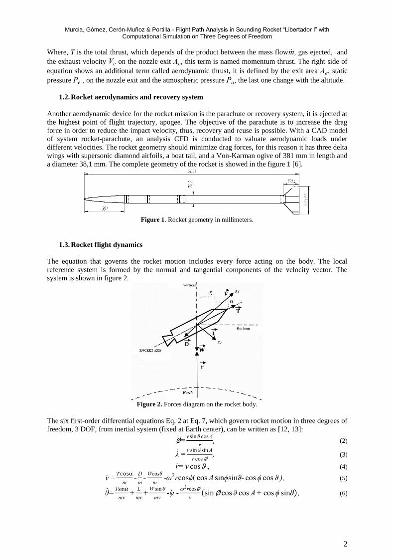
The equation that governs the rocket motion includes every force acting on the body. The local
reference system is formed by the normal and tangential components of the velocity vector. The
system is shown in figure 2.
Figure 2. Forces diagram on the rocket body.
The six first-order differential equations Eq. 2 at Eq. 7, which govern rocket motion in three degrees of
freedom, 3 DOF, from inertial system (fixed at Earth center), can be written as [12, 13]:
∅=v sin ϑ cos A
r, (2)
λ =v sin ϑ sin A
r cos ∅, (3)
r= v cos ϑ , (4)
v =𝑇cosα
m-
D
m-
Wcosϑ
m-ω2rcosϕ( cos A sinϕsinϑ- cos ϕ cos ϑ ), (5)
ϑ=Tsin𝛼
mv+
L
mv+
W sin ϑ
mv-ψ -
ω2rcos∅
v(sin ∅ cos ϑ cos A + cos ϕ sinϑ), (6)

Murcia, Gómez, Cerón-Muñoz & Portilla - Flight Path Analysis in Sounding Rocket “Libertador I” with Computational Simulation on Three Degrees of Freedom
3
Α=v sin ϑ tan ϕ sin A
r+
ω2r sin ϕ cos ϕ sin A
vsinϑ-
2ω(cos ϑ cos ϕ cos A- sin ϑ sin ϕ)
sinϑ , (7)
Where r is the radial vector, v is velocity, α is angle of attack, ϕ and λ are latitude and longitude
angles, ϑ is flight path angle, A is azimuth angle from the Earth’s geometric north to the east, W is the
rocket weight that change on the time, D is aerodynamic drag force, L is lift force and T is the thrust
force. The last three equations include the angular velocity of the Earth in the equator, ω, which
generate Coriolis and centripetal forces [9, 10, 14]. Equations 2 to 7 are mutually coupled and is
necessary a computational code to solve them.
As the vehicle moves through the Earth's atmosphere, aerodynamic forces of drag and lift change due
to the variation of air density with altitude. Therefore, is necessary to implement a standard
atmosphere model such as US1976 [1, 5].
2. METHODOLOGY
This section presents the computational methods for solving differential equations mentioned above.
2.1. Numerical integrator
The numerical integration of Runge-Kutta - RK9 was implemented in order to resolve the differential
equations of three degrees of freedom. The method used is an implicit runge-kutta method (RADAU)
of order 15 known as RA15 which is used in the solution of differential equations in celestial
mechanics [9]. The computer code is written in FORTRAN, it includes data from the thrust provided
by the rocket motor and the aerodynamic coefficients. The time step that is used in the integrator is
1ms. The implemented algorithm is a variant of another one that analyzes the flight path of space
launch vehicles developed in the ObservatorioAstronomico Nacional - OAN from University Nacional
de Colombia - UNAL [7].
3. Results and discussion
3.1. Thrust force as function of time
Inner geometry of the rocket and the solid propellant determinates the thrust force in function of time
on conditions of sea level, Fig. 3. These results are included in the code for modeling mass and the
thrust force for each instant of time. With the mass flow, the net weight of the rocket can be
calculated.
Figure 3. Thrust vs. combustion time solid propellant rocket motor.
3.2. Drag coefficients
Supersonic speeds are generated on the flight path of the rocket. In the Fig. 4 is plotted the drag
coefficient of the body as a function of Mach number, considering that in this case the value of the
angle of attack is constant and equal to 0º; it does not take into account the rotation of the rocket or the
influence of crosswinds [7]. Like the thrust force, the results of the aerodynamics loads obtained by
CFD are added to the flight path code as a subroutine.

Murcia, Gómez, Cerón-Muñoz & Portilla - Flight Path Analysis in Sounding Rocket “Libertador I” with Computational Simulation on Three Degrees of Freedom
4
Figure 4. Rocket drag coefficient with AOA 0º vs. Mach number.
3.3. Flight path
Rocket flight was simulated in the computer code under two cases: launched vertically and with the
opening of its parachute at the apogee. The moments of inertia in the rocket body are not taken into
account, because it is not a simulation of 6DOF; it does not have any control over the rocket body,
phenomenon caused by winds are neglected, an ideal atmosphere is assumed, and its angle of attack
during the entire flight path is equal to 0°. Also, pitching moments caused by the change of the center
of gravity - GC due to the consumption of propellant are neglected.
The first variable taken into account is the change of the mass versus time. As was mentioned, the
mass flow is variable because the burning area of the propellant is not constant. The initial mass of the
rocket is 10 kg and when the propellant is consumed it descends to 5 kg, Fig. 5.
Figure 5. Rocket mass vs time.
3.3.1. Variation on Flight Path Angle (FPA).
Gaori, located in Colombia, was chosen as a possible launch site for the sounding rocket. Its
coordenades are: longitude of 68°41’08¨ W and latitude of 05°31’28¨ N. Military and academic
rockets have been previously tested in this place [3]. First, the flight path is analyzed under the
influence of changes in FPA at launch with a constant azimuth of 90° (west-east), initial mass 10 kg,
final mass 5 kg, without payload, and ballistic flight without parachute or recovery system. The
changes in FPA goes from 0º to 45º with intervals of 15º. Figure 6 shows that the maximum altitude or
apogee is under 22 km with 0º FPA and flight time around 140 s. Similarly, it is observed that
increasing the FPA decreases flight time and altitude (apogee).
Behavior of the total velocity of rocket is obtained too, as is shown in Fig. 7, where the minimum
velocity is achieved in the apogee with 0º FPA. This path is ideal to operate the parachutes. Also, the
plots of the figure 7 show that the velocity increases as the system loses mass and reaches its peak at
the end of combustion, after it begins to go down until to reach the apogee, where gravitational
attraction causes the body starts to fall, increasing its velocity to the point where the air density is
greatest and aerodynamic drag increases due to dynamic pressure (Fig. 8), without parachutes, the
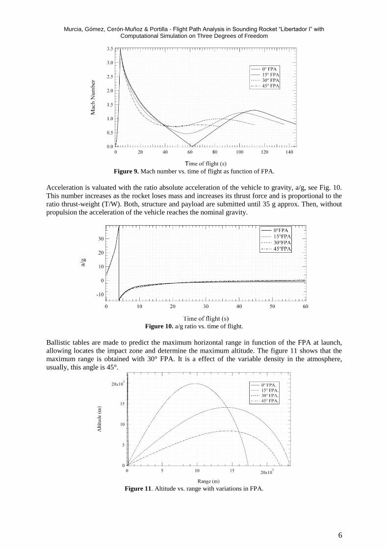
rocket descent at supersonic speeds. Similar to Fig. 7, Fig. 9 shows the Mach number as a function of

Murcia, Gómez, Cerón-Muñoz & Portilla - Flight Path Analysis in Sounding Rocket “Libertador I” with Computational Simulation on Three Degrees of Freedom
5
time, considering that the speed of sound changes with the altitude and temperature of the atmosphere.
The maximum Mach reached by the rocket is 3.5 approx.
Figure 6. Altitude vs. time flight as function of FPA.
Figure 7. Velocity vs. time flight as function of FPA.
Figure 8 shows that the maximum dynamic pressure is achieved at the end of combustion too, where it
reaches a value greater than seven times the atmospheric pressure at sea level, it is the design load to
be supported by the structure, then the dynamic pressure decays as the rocket descends into the Earth's
atmosphere.
Figure 8. Dynamic pressure vs. time of flight as function of FPA.
Murcia, Gómez, Cerón-Muñoz & Portilla - Flight Path Analysis in Sounding Rocket “Libertador I” with Computational Simulation on Three Degrees of Freedom
6
Figure 9. Mach number vs. time of flight as function of FPA.
Acceleration is valuated with the ratio absolute acceleration of the vehicle to gravity, a/g, see Fig. 10.
This number increases as the rocket loses mass and increases its thrust force and is proportional to the
ratio thrust-weight (T/W). Both, structure and payload are submitted until 35 g approx. Then, without
propulsion the acceleration of the vehicle reaches the nominal gravity.
Figure 10. a/g ratio vs. time of flight.
Ballistic tables are made to predict the maximum horizontal range in function of the FPA at launch,
allowing locates the impact zone and determine the maximum altitude. The figure 11 shows that the
maximum range is obtained with 30° FPA. It is a effect of the variable density in the atmosphere,
usually, this angle is 45°.
Figure 11. Altitude vs. range with variations in FPA.
Murcia, Gómez, Cerón-Muñoz & Portilla - Flight Path Analysis in Sounding Rocket “Libertador I” with Computational Simulation on Three Degrees of Freedom
7
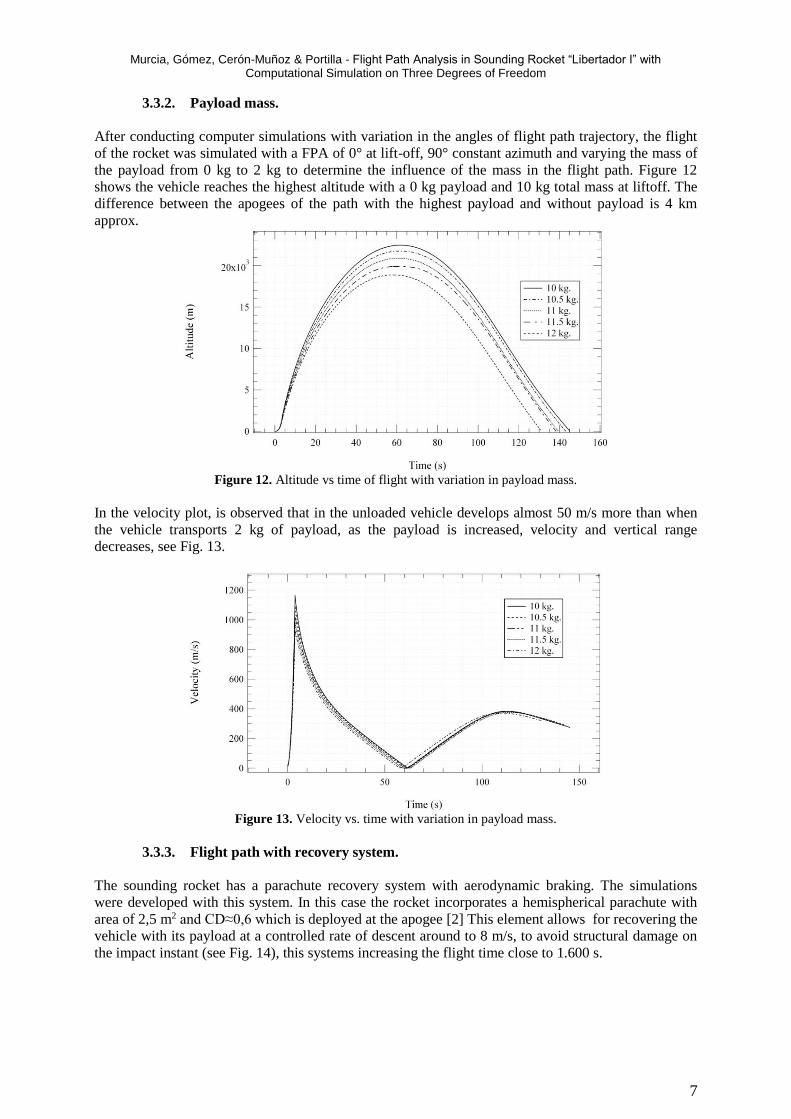
3.3.2. Payload mass.
After conducting computer simulations with variation in the angles of flight path trajectory, the flight
of the rocket was simulated with a FPA of 0° at lift-off, 90° constant azimuth and varying the mass of
the payload from 0 kg to 2 kg to determine the influence of the mass in the flight path. Figure 12
shows the vehicle reaches the highest altitude with a 0 kg payload and 10 kg total mass at liftoff. The
difference between the apogees of the path with the highest payload and without payload is 4 km
approx.
Figure 12. Altitude vs time of flight with variation in payload mass.
In the velocity plot, is observed that in the unloaded vehicle develops almost 50 m/s more than when
the vehicle transports 2 kg of payload, as the payload is increased, velocity and vertical range
decreases, see Fig. 13.
Figure 13. Velocity vs. time with variation in payload mass.
3.3.3. Flight path with recovery system.
The sounding rocket has a parachute recovery system with aerodynamic braking. The simulations
were developed with this system. In this case the rocket incorporates a hemispherical parachute with
area of 2,5 m2 and CD≈0,6 which is deployed at the apogee [2] This element allows for recovering the
vehicle with its payload at a controlled rate of descent around to 8 m/s, to avoid structural damage on
the impact instant (see Fig. 14), this systems increasing the flight time close to 1.600 s.

Murcia, Gómez, Cerón-Muñoz & Portilla - Flight Path Analysis in Sounding Rocket “Libertador I” with Computational Simulation on Three Degrees of Freedom
8
Figure 14. Altitude vs. time of flight with recovery system.
3.3.4. Impact zones
Given the coordinates of the possible launch site were simulated a series of flight paths with 45° FPA
without payload or parachute, were varying the azimuth angle from 0° to 360° at 15° to get the
coordinates of the impact point located nearly 22 km from the launch site. In Figure 15are observed
coordinates of impact zones.
Figure 15. Impact zone coordinates.
4. Conclusions
The use of computational codes to predict the partial performance of the rocket during its flight helps
to validate the design of the vehicle and learn the operating ranges to which instruments onboard will
be subjected, payload and systems recovery. It is expected to corroborate the results of the simulations
with experimental data obtained in the systems, including the rocket engine implementation in a test
stand that is being developed by the group, the wind tunnel data in scale models of rocket for the
aerodynamic and real trajectory data from flight computers and payload.
The design of this sounding rocket serves to perform many experiments in diverse areas of study such
as supersonic aerodynamics, dynamic aerospace structures, propulsion, aerospace medicine, among
others.
The results of the simulations are used to determine the best operating conditions of the vehicle at the
time of its release, according to the payload to be transported and the experiment to be performed, for
example, in the first flight will be transport a mass of 0,5 kg from the data computer to collect
temperature, humidity and atmospheric pressure data, in this case is select a launch with 0° FPA and
can estimate the maximum altitude obtained through simulations with 10,5 kg of total liftoff mass.
The development of these projects is very beneficial to the integration of professionals in various areas
of knowledge, being a productive exercise for an educational institution. There are not antecedents
about this kind of project in Colombia, so the computer simulations shows, first, an approximation
regarding the performance of the rocket, which allows validation and improvement in some systems
both subsystems in the design stage without having to spend resources on production and testing.

Murcia, Gómez, Cerón-Muñoz & Portilla - Flight Path Analysis in Sounding Rocket “Libertador I” with Computational Simulation on Three Degrees of Freedom
9
Additionally, a computational code with 6DOF and 9DOF simulations should be include once the
vehicle would be built and assembled, after which we proceed to verify the results of the simulations
with the flight of the rocket that is expected to be in 2015.
Acknowledgements
The authors wish to express their gratitude to each of the institutions to which they are attached.
REFERENCES
1. Anderson, J., 2010, “Introduction to Flight”. McGraw Hill 6a. ed. New York.
2. Cerón-Muñoz, H. D.,et. al.,2012, “Modelación Dinámica del Sistema de Recuperación de un
Cohete”. Universidad Distrital Francisco José de Caldas. Cuarto Congreso Internacional en
Ciencia y Tecnología Aeroespacial CICTA 2012. Bogotá.
3. Gutiérrez, R., 2012, “Programa Espacial de la Fuerza Aérea Colombiana (FAC), Avances y
Proyección”. Universidad Distrital Francisco José de Caldas. Cuarto Congreso Internacional en
Ciencia y Tecnología Aeroespacial CICTA 2012. Bogotá.
4. Humble, R., Henry, G., and Larson, W., 1995. “Space Propulsion Analysis and Design”.
McGraw Hill 3a. ed. New York.
5. Minzner, R., Champion, K., and Pond, H., 1959, “The ARDC model atmosphere, 1959”. Air
Force Surveys in Geophysics No 115. Cambridge. England.
6. Murcia, J.O.,et. al., 2012. “Diseño Conceptual, Preliminar y Análisis de la Trayectoria de Vuelo
de un Cohete Sonda de Propelente Solidó para Carga Útil de 2 kg”. Universidad Distrital
Francisco José de Caldas. Cuarto Congreso Internacional en Ciencia y Tecnología Aeroespacial
CICTA 2012. Bogotá.
7. Murcia, J.O., 2012, “Estudio de la Trayectoria de un Cohete de Tres Etapas Lanzado desde el
Territorio Colombiano”. Tesis de Maestría en Ciencias Astronomía. Universidad Nacional de
Colombia. Bogotá.
8. NASA, 2011. National Aeronautics and Space Administration. “Sounding Rockets 2011 Annual
Report”. Goddard Space Flight Center. 1a. ed. Wallops Island. Virginia.
9. Portilla, J.G., 1996, “El Problema de los dos Cuerpos y el Problema Principal del Satélite
Artificial en Ecuaciones Diferenciales de Primer Orden”. Revista Academia Colombiana de
Ciencias. Vol. 20. No. 76. pp. 25-32.
10. Portilla, J.G., 2009. “Elementos de Astronomía de Posición”. Unibiblos. 1a.ed. Bogotá.
11. Sutton, G.P. and Biblarz, O., 2010. “Rocket Propulsion Elements”. Jhon Wiley and Sons, Inc. 8a.
ed. New York.
12. Tewari, A., 2006. “Atmospheric and Space Flight Dynamics”. Birkhauser. 1a. ed. Berlin.
13. Weiland, C., 2010. “Computational Space Flight Mechanics”. Springer. 1a. ed. Berlin.
14. Zipfel, P., 2007,“Modeling and Simulation of Aerospace Vehicle Dynamics”. AIAA. 2a. ed.