Embed Size (px)
Citation preview

Flight Operational Safety Assessment
Requirements for New Procedures (RNP-AR)
Cláudia Alexandra Fernandes Cabaço
Dissertação para obtenção do Grau de Mestre em
Engenharia Aeroespacial
Júri Presidente: Prof. Doutor Fernando Lau
Orientador: Profª Doutora Maria do Rosário Macário
Vogais: Prof. Doutor Jorge Miguel Reis Silva – Universidade da Beira Interior
Outubro 2010

1
Table of Contents
I - RESUMO ............................................................................................................................................. 3
II - ABSTRACT ........................................................................................................................................ 4
III - ACKNOLEDGEMENTS ..................................................................................................................... 5
IV - LIST OF FIGURES ........................................................................................................................... 6
V - LIST OF TABLES ............................................................................................................................... 7
VI - LIST OF CHARTS ............................................................................................................................. 7
VII - LIST OF EQUATIONS ..................................................................................................................... 7
VIII - LIST OF ABBREVIATIONS ............................................................................................................ 8
IX - LIST OF DEFINITIONS................................................................................................................... 11
X - EXECUTIVE SUMMARY ................................................................................................................. 13
1 - INTRODUCTION AND OBJECTIVES .............................................................................................. 18
2- STATE OF THE ART ........................................................................................................................ 22
2.1 Safety Assessment .......................................................................................................................... 22
2.1.1 Hazard Identification Methods ...................................................................................................... 31
2.1.2 Risk Assessment Methods ........................................................................................................... 34
2.2 The RNP concept ............................................................................................................................ 47
3 - RNP-AR ............................................................................................................................................ 57
3.1 RNP-AR Advantages ....................................................................................................................... 63
3.2 RNP-AR Operational Approval - FOSA Requirement ..................................................................... 64
4 – FOSA METHODOLOGY - THE CASE OF RNP-AR ....................................................................... 68
4.1 Step 1: System and safety criteria definition ................................................................................... 69
4.1.1 SyStem Definition ......................................................................................................................... 69
4.1.2 Safety Criteria Definition ............................................................................................................... 71
4.2 Step 2: Hazards Identification ......................................................................................................... 73
4.3 Step 3: Hazard Severity eSTIMATION ............................................................................................ 79
4.4 Step 4: Hazard Likelihood estimation .............................................................................................. 80
4.5 Step 5: Risk Estimation ................................................................................................................... 82
4.6 Step 6: Risk Acceptability ................................................................................................................ 84
4.7 Step 7: Safety Assessment Documentation .................................................................................... 84
4.8 Monitoring Proposal ......................................................................................................................... 84

2
5 – CONCLUSIONS AND RECOMMENDATIONS ............................................................................... 86
6 – BIBLIOGRAPHY .............................................................................................................................. 90
APPENDIX I .......................................................................................................................................... 93
APPENDIX II ......................................................................................................................................... 94
APPENDIX III ........................................................................................................................................ 95
APPENDIX IV ........................................................................................................................................ 96
APPENDIX V ....................................................................................................................................... 100
APPENDIX VI ...................................................................................................................................... 101

3
I - RESUMO
O mais recente procedimento de navegação aérea aplicável à fase de aproximação, é conhecido por
RNP-AR - Required Navigation Performance – Authorization Required. A implementação deste novo
conceito operacional tem o potencial de contribuir significativamente para o nível de segurança das
operações de voo, por isso uma das condições do processo de aprovação operacional é a execução
de uma avaliação de segurança da operação de voo – FOSA. A finalidade deste requisito é
demonstrar que o nível de segurança exigido é atingido. No entanto, não está disponível ao domínio
público documentação oficial produzida pela EASA, sobre o que é uma metodologia FOSA.
O objectivo desta investigação é auxiliar os operadores aeronáuticos no cumprimento deste requisito.
Para tal, foram analisadas metodologias de avaliação de segurança actualmente disponíveis.
Esta análise esclareceu que uma metodologia FOSA não é diferente da metodologia genérica de
avaliação de segurança e propõe uma metodologia prática, que estabelece um equilíbrio entre
avaliação numérica e qualitativa, contemplando a avaliação da interdependência dos potenciais riscos
de todas as áreas participativas, com base no processo de avaliação de segurança de 7 fases,
proposto pela ICAO. Para a execução das três fases principais, foram seleccionadas as ferramentas:
técnica de informante-chave, sessões de brainstorming, softwares Excel e @ Risk, a fim de beneficiar
dos recursos, experiência e conhecimentos disponíveis na maioria dos operadores aeronáuticos.
Concluiu-se também que, independentemente das ferramentas utilizadas em cada uma das fases, a
avaliação de segurança será sempre uma metodologia subjectiva, dependente da experiência
daqueles que nela participam.
Palavras-chave: RNP-AR, FOSA, Avaliação de Segurança, Avaliação de Risco, Segurança, Risco

4
II - ABSTRACT
The utmost development of aircraft operational performance based on navigation performance for
approach and missed approach, using area navigation avionics systems is known as RNP-AR.
Because the implementation of this new operational concept has the potential to contribute
significantly to the safety level of flight operations, EASA requires operators to perform a Flight
Operational Safety Assessment (FOSA) as part of the operational approval process. The purpose of
this FOSA is to demonstrate that the target level of safety is achieved. However, no official
documentation produced or supported by EASA is available to the public domain regarding what a
FOSA methodology is.
The purpose of this research is to assist Aircraft Operators with this requisite. In order to achieve this
goal, an analysis of the main methods currently available was performed. This analysis clarified that a
FOSA is no different than a safety assessment and proposes a practical methodology, balancing
between numeric and qualitative assessment and assessment of the interdependence of all potential
hazards from all areas, based on the ICAO 7-step safety assessment process. For the execution of
the three main steps the use of key informant technique, brainstorming sessions, Excel and @Risk
software‟s was selected, in order to benefit from the resources, experience and expertise available at
the majority of the aircraft operators.
It also concluded that independently of the tools used for each step, safety assessment will always be
a subjective methodology, highly dependent of the expertise of those participating in it.
Keywords: RNP-AR, FOSA, Safety Assessment, Risk Assessment, Safety, Risk, Hazard

5
III - ACKNOLEDGEMENTS
I would like to thank my Supervisor, Profª Rosário Macário, for believing in the theme of this research
from the first moment I proposed it, for her assistance in providing me direction and continuous
technical support, encouragement and patient, despite the challenges this research has experienced.
Sincere thanks to Nuno Aghdassi, Paulo Pestana, Marco Pereira and Erik Verheijden, for their
continuous support and enthusiasm for this research and for devoting their precious time in performing
the hazard synergy matrix exercise.
Special thanks to Catherine Thompson for introducing me to the RNP-AR‟s theme and to Mischa
Frank for providing me support material, for their continuous encouragement to pursue this research
and exchanges of knowledge, which helped enrich this experience.
To my family I show gratitude in our mother tongue…
Agradeço à minha família, em especial aos meus pais, Isabel e Fernando, pelo seu constante e
incondicional apoio ao longo de toda a minha vida; por serem a minha fonte inesgotável de motivação
e pela sua perseverança em não me deixar desistir quando a minha motivação era reduzida.
Last but not least, a big and special thank you to my partner for life, Pedro, without whose love, patient
and encouragement I would have not finished this research.
Thank you.
Cláudia Cabaço
October, 2010

6
IV - LIST OF FIGURES
Figure 1 – ICAO Risk Management Process, [40] ................................................................................ 24
Figure 2 – Contributing factors to the safety level of the aviation industry. ........................................... 28
Figure 3 - Safety assessment representation........................................................................................ 27
Figure 4 – SIRA Method – ARMS [39] .................................................................................................. 29
Figure 5 – Risk Assessment Sample Matrix [4]..................................................................................... 36
Figure 6 – Probability and Severity relationship for Failure Condition Effects. [15] .............................. 38
Figure 7 – Navigation Procedure – Safety Analysis Integration ............................................................ 40
Figure 8 – Example of the FTA of an Airplane Crash, [24] ................................................................... 42
Figure 9 – Conventional Instrument Flight Procedure [37] .................................................................... 47
Figure 10 – RNAV Procedure [37] ......................................................................................................... 48
Figure 11 – RNP Capability and Containment Limit .............................................................................. 50
Figure 12 – Total Navigation System Error – Lateral and Longitudinal Directions [48] ........................ 51
Figure 13 – Total System Error per Dimension .................................................................................... 51
Figure 14 – System Error – Lateral Dimension (95%) [37] ................................................................... 52
Figure 15 – System error - Along Track [37] ......................................................................................... 52
Figure 16 – PBN Benefits [49] ............................................................................................................... 55
Figure 17 – Flight Path trajectories evolution up to RNP under PBN concept [49] ............................... 56
Figure 18 – RNAV and RN in all phases of the flight [48] ..................................................................... 58
Figure 19 – Differences between Conventional RNP and RNP-AR approach [59] ............................... 59
Figure 20 –Curved segments – Radius-to-Fix [46] ............................................................................... 60
Figure 21 – Improved access to Bishop Airport [49] ............................................................................. 60
Figure 22 – Traffic de-confliction between JFK and La Guardia Airport [49] ........................................ 61
Figure 23 – Lateral Protection (plan view): Non RNP-AR vs. RNP-AR. [46] ........................................ 61
Figure 24 – RNP-AR Segment width and lateral protection (cross section view) [46] .......................... 62
Figure 25 – Gulfstream GV-SP (G550) cockpit [27] .............................................................................. 62
Figure 26 – Benefits of RNP-AR: approaches for parallel, converging and adjacent runways [49]...... 64
Figure 27 – Benefits of RNP-AR: Example of a tailored routing [48] ................................................... 64
Figure 28 – RNP-AR System elements interaction ............................................................................... 70
Figure 29 – Hazard Synergy Matrix ....................................................................................................... 76
7
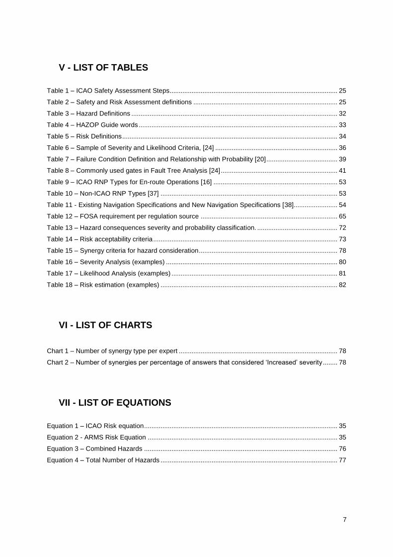
V - LIST OF TABLES
Table 1 – ICAO Safety Assessment Steps ............................................................................................ 25
Table 2 – Safety and Risk Assessment definitions ............................................................................... 25
Table 3 – Hazard Definitions ................................................................................................................. 32
Table 4 – HAZOP Guide words ............................................................................................................. 33
Table 5 – Risk Definitions ...................................................................................................................... 34
Table 6 – Sample of Severity and Likelihood Criteria, [24] ................................................................... 36
Table 7 – Failure Condition Definition and Relationship with Probability [20] ....................................... 39
Table 8 – Commonly used gates in Fault Tree Analysis [24] ................................................................ 41
Table 9 – ICAO RNP Types for En-route Operations [16] .................................................................... 53
Table 10 – Non-ICAO RNP Types [37] ................................................................................................. 53
Table 11 - Existing Navigation Specifications and New Navigation Specifications [38]........................ 54
Table 12 – FOSA requirement per regulation source ........................................................................... 65
Table 13 – Hazard consequences severity and probability classification. ............................................ 72
Table 14 – Risk acceptability criteria ..................................................................................................... 73
Table 15 – Synergy criteria for hazard consideration ............................................................................ 78
Table 16 – Severity Analysis (examples) .............................................................................................. 80
Table 17 – Likelihood Analysis (examples) ........................................................................................... 81
Table 18 – Risk estimation (examples) ................................................................................................. 82
VI - LIST OF CHARTS
Chart 1 – Number of synergy type per expert ....................................................................................... 78
Chart 2 – Number of synergies per percentage of answers that considered „Increased‟ severity ........ 78
VII - LIST OF EQUATIONS
Equation 1 – ICAO Risk equation .......................................................................................................... 35
Equation 2 - ARMS Risk Equation ........................................................................................................ 35
Equation 3 – Combined Hazards .......................................................................................................... 76
Equation 4 – Total Number of Hazards ................................................................................................. 77

8
VIII - LIST OF ABBREVIATIONS
ABRM – Analytical Blunder Risk Model
ADF - Automatic Direction Finder
AFM – Aircraft Flight Manual
AIP – Aeronautical Instrument Procedure
AOC – Aircraft Operations Certificate
APCH – Approach
ARMS – Airline Risk Management Solutions
ATC – Air Traffic Controller
ATS – Air Traffic Service
ATM – Air Traffic Management
CCF – Common Cause Failure
CFIT – Control Flight Into Terrain
CNS – Communication, Navigation and Surveillance
DA/H - Decision altitude/height
DME – Distance Measuring Equipment
EASA – European Aviation Safety Agency
EGPWS – Enhanced Ground Proximity Warning System
ERC – Event Risk Classification
ETA – Event Tree Analysis
EUROCAE – European Organization for Civil Aviation Equipment
FAA – Federal Aviation Administration
FANS – Future Air Navigation System
FAF – Final Approach Fix
FDR – Flight Data Record
FDM – Flight Data Monitoring
FHA – Fault Hazard Analysis
FMS – Flight Management System
FORAS – Flight Operational Risk Assessment System
FOSA – Flight Operational Safety Assessment
FTA – Fault Tree Analysis
FTE – Flight Technical Error
GNSS - Global Navigation Satellite System
GNSSP - Global Navigation Satellite System Panel
HFACS – Human Factors Analysis and Classification System
HAZOP – Hazard and Operability Tool
IFR – Instrument Flight Rules
ICAO – International Civil Aviation Authority
ILS – Instrument Landing System

9
INAC – Instituto Nacional de Aviação Civil
IMC – Instrument Metereological Condition
INS - Inertial Navigation System
LOC - Localizer
LORAN-C – Long Range Navigation
MEL – Minimum Equipment List
MLS – Microwave Landing System
NAA – National Aviation Authority
NASA – National Aeronautics and Space Administration
NAVAID – Navigation Aid
NDB – Non Directional Beacon
NLR – National Aerospace Laboratory
NM – Nautical Miles
NOTAM – Notice to Airmen
OCA/H - Obstacle Clearance Altitude/Height
OEM – Original Equipment Manufacturer
OEI – One Engine Inoperative
PBN – Performance Based Navigation
PRA – Probabilistic Risk Assessment
QAR – Quick Access Recorder
QRAS – Quantitative Risk Assessment System
RAIM – Receiver Autonomous Integrity Monitoring
RF – Radius to Fix
RGCSP - Review of the General Concept of Separation Panel
RNPC - Required Navigation Performance Capability
RNAV - Area Navigation
RNP – Required Navigation Performance
RNP-AR - Required Navigation Performance-Authorization Required
RNPSORSG – Required Navigation Performance Special Operations Requirements Study Group
RTCA – Radio Technical Commission for Aeronautics
SAM – Safety Assessment Methodology
SARPS – Standards and Recommended Practices
SIDs – Standard Instrument Departures
SIRA – Safety Issue Risk Assessment
SSA – System Safety Assessment
SMS – Safety Management System
SRM – Safety Risk Management
USA – United States of America
TAWS – Terrain Awareness Warning System
THERP - Technique for Human Error Rate Prediction

10
TOPAZ – Traffic Organization and Perturbation Analyzer.
TLS – Target Level of Safety
TSE – Total System Error
VEB – Vertical Error Budget
VOR – Very High Frequency Omni Directional Radio Range

11
IX - LIST OF DEFINITIONS
Along-track error - A fix error along the flight track resulting from the total error contributions. [16]
Containment limit (cross-track vs. along-track) - A region about an aircraft desired position, as determined by the airborne navigation system, which contains the true position of the aircraft to a probability of 99.999 per cent. [16]
Containment value (containment distance) - The distance from the intended position within which flights would be found for at least ninety-five per cent of the total flying time. [16]
Cross-track error - The perpendicular deviation to the left or right of the desired aircraft track. [16] En-route operations - Operations conducted on published ATS routes, direct point-to-point operations between defined way-points or along great circle routes which are other than take-off, landing, departure, arrival or terminal operations. [16]
Error: An omission or incorrect action by a crewmember or maintenance personnel, or a mistake in
requirements, design, or implementation.
Failure: An occurrence, which affects the operation of a component, part, or element such that it can
no longer function as intended (this includes both loss of function and malfunction). NOTE: Errors may
cause failures, but are not considered failures. [21]
Failure condition: A condition having an effect on the aeroplane and/or its occupants, either direct or
consequential, which is caused or contributed to by one or more failures or errors, considering flight
phase and relevant adverse operational or environmental conditions, or external events. [21]
Likelihood – the estimated probability or frequency, in quantitative or qualitative terms, of an
occurrence related to the hazard.
Navigation - The means by which an aircraft is given guidance to travel from one known position to another known position. [16]
Navigation guidance - The calculation of steering commands to maintain the desired track from the present aircraft position to a new position. [16]
Receiver Autonomous Integrity Monitoring (RAIM) – A technique whereby a GPS
receiver/processor determines the integrity of the GPS navigation signals using only GPS signals or
GPS signals augmented with altitude. This determination is achieved by a consistency check among
redundant pseudo-range measurements. At least one satellite in addition to those required for
navigation must be view for the receiver to perform the RAIM function. [19]
Residual safety risk – The remaining safety risk that exists after all control techniques have been
implemented or exhausted and all controls have been verified. Only verified controls can be used for
the assessment of residual safety risk. [24]
Safety Issue – Manifestation of a hazard or combination of several hazards in a specific context. [40]
Safety risk control – Anything that reduces or mitigates the safety risk of a hazard. Safety risk
controls must be written in requirements language, measurable and monitored to ensure
effectiveness. [24]

12
Serious Incident – An incident involving circumstances indicating that an accident nearly occurred.
The difference between accident and serious incident lies only in the result. [50]
Severity – The consequence or impact of a hazard in terms of degree of loss or harm. [50]

13
X - EXECUTIVE SUMMARY
The airspace density is limited by the vertical and horizontal separation between aircrafts. Currently
this separation is established by State requirements, achieved by on-board and ground equipment
requirements associated with navigation requisites. Due to the continuing air traffic increase, in order
to allow the air space capacity to growth, new procedures and navigation concepts are necessary.
Therefore, it is necessary to ensure that acceptable levels of safety risk are met.
One of the latest aircraft navigation operational concept to be regulated and its use permitted to
aircraft operators is Required Navigation Performance – Authorization Required. This type of
operation entails aircraft qualification, operator approval and instrument procedures to be designed in
order to address the majority of technical and procedural factors. Once new operational concepts and
its implementation have the potential to contribute significantly to the safety level and efficiency of
flight operations, EASA [Appendix I] requires operators to perform a Flight Operational Safety
Assessment (FOSA) as part of the operator approval process for this navigation requirement.
A safety assessment consists in the process of hazards identification and the assessment of the
associated risks against an acceptable level of safety, which for the case of RNP-AR operations is a
probability of risk collision of less than 10-7
per flight or approach.
The purpose of this type of methodology is to support the formal assessment of the magnitude of the
safety risks posed by certain occurrences due to the new type of operation that the operator will or is
expected to experience, during the decision making process.
The scope of this research is to propose a flight operational safety assessment methodology to
support the implementation of RNP-AR into the daily operation of an European Aircraft Operator,
specifically a business jet operator. The main objective is to ensure the safe introduction of the use of
RNP-AR.
The aim of this research is to present a clear, coherent, complete and integrated approach to aircraft
operators to perform a FOSA, part of the document package to be sent to the national authority
requiring operational approval to conduct RNP-AR operations.
In order to achieve this goal a top down approach was used, constituted by the following parts:
Safety assessment and risk assessment state of the art analysis;
Clarification of the differences between a safety and a risk assessment;
Assessment of existing safety and risk assessment methods and tools;
RNP state of the art analysis;
RNP-AR analysis - It is not the intention of this research to fully investigate the details that
allow the design of a RNP-AR approach procedure. Therefore only a summary of the main
characteristics of RNP-AR approaches procedures, which differentiate from any other RNP

14
approach, will be provided. Further guidance and details on procedure design requirements
are available in ICAO [Appendix I] RNP-AR manual [46] ;
Analysis of the RNP-AR FOSA regulatory requisite;
Development a practical FOSA methodology, based on existing methods and tools readily
available to the majority of the aircraft operators;
Test the proposed FOSA methodology in a business jet operator;
Investigation revealed that safety assessment and risk assessment expressions are widely used in the
aviation industry across the world as processes to assess the safety and/or risk level of operations,
but there is a lack of terminology standardization and understanding regarding these two approaches
and their differences.
Analysis of the different meanings for safety and risk assessment used by different stakeholders
revealed that none of them intends to be prescriptive, rather to provide guidance regarding acceptable
methods that can be adopted and adapted to systematically manage safety in a rational and thoughtful
way, independently of the environment being assessed. These two approaches share the same
purpose and goal and what sets the distinction between the two is their applicability, i.e. a safety
assessment is applied to a new system/operation/process while risk assessment is applied to a known
or on-going operation.
If a safety assessment and a FOSA share the same objective, i.e. demonstrate that the acceptable
level of safety of an operation is met (target level of safety, as per EASA AMC 20-26, [28]), according
to a pre-set safety criteria, and both are to be applicable to a new operation, than a FOSA
methodology should be no different from a generic safety assessment methodology, having per basis
the 7 step process safety assessment widely accepted in the aviation industry.
1) System analysis and safety criteria definition
2) Hazards identification
3) Estimation of the hazard(s) consequences severity
4) Estimation of the hazard(s) occurrence likelihood
5) Risk estimation
6) Risk acceptability/mitigation
7) Safety assessment documentation
The safety assessment results from the combination of methods and/or tools used for each of the
steps. Three main steps drive the safety assessment: hazard identification, hazard severity
identification and hazard likelihood estimation. The methods and tools used for each one set the
difference between safety and risk assessments available in the public domain. All types of tools
analyzed are time consuming and require the participation of subject matter experts, the more the
better as the more reliable the results will be. It is concluded that independently of the tools selected
safety and risk assessment will always be a subjective assessment, highly dependent of the expertise

15
of the participants. The larger the representation the better, because - more data will be available for
identifying the distributions and hence the higher the confidence level in the results is.
For the execution of the three main steps and in order to benefit from the resources, experience and
expertise available at the majority of the aircraft operators, from a practical and finance perspective,
for the case of RNP-AR the use of key informant technique, brainstorming sessions and Excel
software from Microsoft was selected.
RNP-AR approach operations safety assessment requires input from 3 main areas: Systems Integrity,
Aircraft Operations and Air Navigation Services, which account for all the RNP-AR requirements to be
addressed for the operational approval.
Because an accident rarely occurs due to a single factor but rather due to a chain of contributing
factors/hazards/errors, besides assessing each individual hazard, it is necessary to assess their
synergy and its impact in the severity on the final outcome when compared to the outcome severity of
a standalone hazard occurrence. In order to assist this step, the concept of „Hazard Synergy Matrix‟
was created.
It was requested to 14 experts from a Business Jet Operator which aims to request RNP-AR
operational approval in a near future, to analyse the synergy of the 37 generic hazards to RNP-AR,
using the „Hazard Matrix Synergy‟. This group accounted expertise from the following areas: Flight
Crew – Flight Operations, Flight Crew Training, Dispatch, Maintenance and Safety (accident/incident
investigation expertise). In the absence of identical answers from all key informants and in order to
decide whether or not the synergy needs to be considered as an additional hazard, statistical analysis
were performed for each possible synergy. Only positive synergies were considered by more than
50% of the experts were considered. Unfortunately at the time of production of this report only 4
answers had been received.
The statistic analysis of the answers, revealed 558 new hazards. This results in a total of 595 hazards
to be assessed. The different results from each expert substantiate the subjectivity of the hazard
analysis process. From the analysis of the results it was possible to conclude that the hazard synergy
identification process is dependent of:
- Individual area expertise;
- Time available to perform the analysis;
- Knowledge of the operation under assessment;
- Knowledge of safety/risk assessment processes (especially of what a hazard is).
Should a different group of experts have been used, then the result could have been different.
The expert‟s participation on the following steps was not possible, due to lack of availability.
Nevertheless a proposal on how to perform each of the following steps is left to be tested.
The use of brainstorming sessions and statistical analysis, similar to the hazard identification step are
proposed.

16
One of the main challenges is the establishment of a numerical relationship between the probability of
occurrence between the hazards resultant from the airplane systems integrity, air navigation services
and the human interactions/errors, due to lack of quantitative data from aircraft operations.
Furthermore the human interaction is in fact the larger contributor to the impairment of the safety level
of the operation and the contributor with the highest level of uncertainty. Therefore the main challenge
lies in the identification of the likelihood of occurrence of these types of hazards.
The demonstration that the probability of the aircraft exiting the lateral and vertical extent of the
obstacle clearance volume must not exceed 10-7
, per flight hour is achieved by demonstrating that
each one of the potential contributing factors has an „Acceptable‟ level of risk, according to the risk
acceptability criteria. Should any potential hazard have a „Not-acceptable‟ risk, mitigating actions need
to be implemented to either reduce its likelihood of occurrence or its severity, or preferably reduce
both components.
Because the safety assessment steps that drive it are dependent of expertise inputs, consensus will
most probably not be achieved between all the participants and due to the high number of hazards, it
becomes an impractical task to perform the risk estimation manually. Due to the variability and
uncertainty of the parameters, severity and likelihood, a probabilistic approach is recommended to be
used. It is therefore advantageous the use of a mathematical tool to support the risk estimation
process, by facilitating the quantitative method for assessing the impact of risk decisions and
determining all possible outcomes for each hazard. The use of @Risk, from Palisade, is
recommended to support the risk estimation and decision making process regarding risk acceptability
or not.
The use of @Risk tool is only beneficial if assessing a large amount of the data, unfortunately due to
unavailability of experts participation from the operator contacted, it was not possible to gather this
data and consequently the use of @Risk was not tested.
Hence it is concluded that a safety assessment of an aircraft operation:
Requires the use of a methodology oriented to performance-based, where in order to meet
the safety objective it is necessary to consider qualitative and quantitative analyses and
assessment of the interdependence of all potential hazards from all areas, namely navigation
systems, aircraft systems, operational procedures and operational environment. Hazard
synergy matrix assists in the interdependence analysis.
Must balance between probabilistic and qualitative assessment.
Independently of the tools used for each step, will always be a subjective methodology, highly
dependent of the expertise and knowledge of those participating in the safety assessment.
The negative impact of this subjectivity can only be reduced through a good representation of
all the areas involved in the operation.

17
It is impractical to develop a safety assessment method that fits all objects of assessment,
such as all aircraft operations, all aircraft types, all airspace users, all navigation users, etc..
It is important to understand that a safety assessment tool itself does not guarantee a safe operation
and that it is only an additional tool to help the Aircraft Operator and the Aviation Regulatory Authority
to make sound safety decisions in order to demonstrate that the safety criteria is met. Operational
safety is a shared responsibility between all stakeholders.

18
1 - INTRODUCTION AND OBJECTIVES
The rapid worldwide increase of air traffic and aircraft technological development demands a rapidly
changing and adaptation of aviation operational environments, where the boundaries are rarely limited
to single countries. Along with this continuous change, the assurance of safe aviation operations is
paramount. However, absolute safety does not exist and it is unachievable to completely eliminate
accidents and serious incidents. Failures will always occur, in spite of the most accomplished and
prevention efforts, as it is impossible to completely eliminate all risks. No human-made
system/technology can be free from risk and error. However risk and error are acceptable if controlled
in an inherently safe system. So how is it possible to ensure that aircraft operations are safe if it is not
possible to eliminate all risks? What is safety? As per ICAO definition [15], page 16, Safety “is the
state in which the risk of harm to persons or property damage is, reduced to, and maintained at or
below, an acceptable level through a continuing process of hazard identification and risk
management.” Therefore whenever new operations, equipments are to be put in place, it is necessary
to ensure that the acceptable level of safety is guaranteed.
Safety and risk assessment are the two main terms used in the aviation to address the demonstration
of the safety level of an aircraft operation. The purpose of this assessment is to identify the safety level
associated to a specific action/operation through the identification of the expected risk(s), by providing
guidance in the decision-making roles in order to either accept or not the risk(s) to which the operation
is expected to be exposed. Through this evaluation, based on a pre-determined acceptable level of
risk, mitigation strategies/corrective actions can and should be implemented according to the specific
safety risks in order to reduce their potential effect(s).
Nowadays, the terminology safety assessment and risk assessment has merged into each other in
such a way that it became difficult to understand whether or not they represent two distinct methods. If
distinct, in which situations should we use each of them; or if they complement each other and the
performance of one‟s mandates the accomplishment of the other. Nevertheless, despite these
uncertainties, it is widely understood that their ultimate objective is common - identify what and where
actions need to be considered to guarantee the planned acceptable level of safety.
The Required Navigation Performance - RNP is a concept that is used in the aviation industry for
some years. It consists on the ability of the aircraft navigation system to monitor its achieved
navigation performance and to inform the pilot whether the operational requirement is or is not being
met during its operation, and on the optimization of instrument procedure design based for aircraft
required navigation performance. It allows reducing aircraft separation en route and in terminal areas
to optimize arrival and departures procedures, reducing operating minima over and above traditional
non-precision and conventional RNAV approaches.

19
The utmost development of aircraft operational performance based on navigation performance for
approach, missed approach and departure, using area navigation avionics systems where
authorization is required is known under two different names:
FAA [Appendix I] refer to it as RNP SAAAR - Special Aircraft and Aircrew Authorization
Required – published in December 15th 2005 through AC 90-101 [3];
ICAO and EASA refer to it as Required Navigation Performance – Authorization Required,
RNP-AR
o ICAO first introduced this concept in the PBN Manual, [37].
o EASA published RNP-AR in Decision 2009/019/R, of 16th December, 2009, amending
the „General Acceptable Means of Compliance of Airworthiness of Products, Parts
and Appliances («AMC-20») – AMC 20-26, [28];
Albeit the requirements established by FAA and EASA are almost identical, the requirements
established by EASA are a little more stringent. This research follows EASA requirements and
guidelines. These approach procedures are characterized by:
RNP values ≤ 0.3 NM, i.e. an obstacle clearance of 0.3NM or less from the aircraft flight track;
Curved flight path before and after the final approach point (where it is decided to continue the
approach or perform a go-around);
Protections areas laterally limited to 2xRNP value without any additional buffer, maximum
0.6NM;
The application of RNP-AR procedures to terminal area and approach operations is expected to
provide an opportunity to utilize current aircraft capability and performance in order to improve safety,
efficiency and capacity through the incorporation of additional navigational accuracy, integrity and
functional capabilities. It allows operations to be implemented in circumstances where other types of
approach procedures are not operationally satisfactory or possible. Safety will be improved when
RNP-AR procedures replace visual procedures or non-precision approaches, and efficiency through
more repeatable and optimum flight paths. Capacity will be improved by de-conflicting traffic during
instrument conditions.
RNP-AR operations are accessible to aircraft and operators complying with specific airworthiness and
operational requirements. Aircraft operators have to apply to their competent State Aeronautical
Authority for operational approval. As part of the operational approval process, the operator must
demonstrate that all appropriate requirements have been properly addressed and that the aimed
target level of safety is achieved, by performing of a Flight Operational Safety Assessment - FOSA.
The target level of safety or acceptable level of safety for RNP-AR operations is a probability of risk
collision of less than 10-7
per flight or approach.
However, no official documentation produced or supported by ICAO or EASA is available to the public
domain regarding what a FOSA methodology is. How can the Operator demonstrate to the Authority
that its RNP-AR operations meet the target level of safety established in the regulations? Is it a FOSA
the same as safety assessment or a risk assessment? But what is the difference between a safety and

20
a risk assessment? Is a FOSA methodology different from a generic safety assessment, when they
aim for the same objective?
Additionally, the major difference between European and USA regulation is that the latter does not
require a FOSA, which means that no previous experience can be used from USA aircraft operators to
support the compliance of this item.
Although several aircraft operators are known to request this type of operational approval, at the time
of production of this report no European aircraft operator had been granted operational approval and
several have raised concerns regarding the lack of guidance on the subject of the FOSA methodology.
Also several airports are under approval process to allow aircraft operators to fly into it under RNP-AR
approach procedures. At the time of production of this report, a working draft document, produced by
Eurocontrol presenting guidance on FOSA for RNP-AR applications was made available by EASA,
[45]. It is believed that EASA supports this approach however; no official communication about this
document has been made to the European Aircraft Operators. On October 20th, 2010 EASA will held a
workshop with the aim to review the process of RNP (AR) operations within the emerging EU
regulatory framework. It is expected Eurocontrol‟s document to be officially presented at this meeting.
In the mean time, from the AOC perspective, once it is focused in obtaining the operational approval
the question still remains: What is a FOSA methodology? How can the Operator demonstrate to the
Authority that its flight operations meet the target level of safety established in the regulations?
The objective of this research is to assist European aircraft operators (AOC holders) with the
compliance of the FOSA requisite, by providing an acceptable mean of compliance. It aims to be a
clear, coherent, complete and integrated approach for aircraft operators to perform a FOSA, part of
the document package to be sent to the national authority requiring operational approval to conduct
RNP-AR operations. For achievement of this goal, this research endeavors to:
Clarify the distinction between a safety and a risk assessment;
Clarify if a FOSA is any different from a generic safety assessment;
Clarify under which conditions a FOSA is required;
Propose a FOSA practical methodology, balancing between numeric and qualitative
assessment, to be applied by an aircraft operator as part of its RNP-AR operational approval
process.
In order to achieve this goal a top down approach to the problem was used, comprising the following
parts:
Safety assessment and risk assessment state of the art analysis;
Clarification of the differences between a safety and a risk assessment;
Assessment of existing safety and risk assessment methods and tools;
RNP state of the art analysis;

21
RNP-AR analysis - It is not the intention of this research to fully investigate the details that
allow the design of a RNP-AR approach procedure. Therefore only a summary of the main
characteristics of RNP-AR approaches procedures, which differentiate from any other RNP
approach, will be provided. Further guidance and details on procedure design requirements
are available in ICAO RNP-AR manual [46];
Analysis of the RNP-AR FOSA regulatory requisite;
Development a practical FOSA methodology, based on existing methods and tools readily
available to the majority of the aircraft operators;
Test the proposed FOSA methodology in a business jet operator.

22
2- STATE OF THE ART
2.1 SAFETY ASSESSMENT
Over the yearS aviation regulatory authorities and industry experts have been continuously developing
and enhancing methods and tools to assess the continuous improvement of the aviation industry, with
the aim to guarantee acceptable levels of safety while improving flight operational capability,
increasing airspace efficiency and reducing operational costs.
The concept of safety in the aviation industry may have different perceptions; ICAO in its Safety
Management Manual [9] highlights some of them:
Zero accidents or serious incidents;
Freedom from hazards;
Attitudes of employees of aviation organizations towards unsafe acts and conditions;
Error avoidance;
Regulatory compliance.
All of these perceptions have a common understatement: ensure a control state over anything “that
can precipitate bad or damaging outcomes”. It is accepted that this control can only be relative rather
than absolute, as there is no such thing as zero accidents or serious incidents or even absolute
freedom from hazards. Therefore when it is mentioned „acceptable level of safety‟ it refers to a
reasonable degree of control of parameters control within a system, that can contribute to undesirable
scenarios. This acceptable level of safety can be set of numerous ways, based on quantitative or
qualitative data, regulatory requirements, operators‟ requirements, manufacturer requirements, user‟s
expectations (public opinion), etc. and it is dependent of the activity under safety assessment.
However, independently of the type of criteria and the numerous methods available to identify it, a
high degree of subjectivity is always associated to it.
For the purpose of the aviation industry ICAO defines Safety as: “The state in which the possibility of
harm to persons or of property damage is reduced to, and maintained at or below, an acceptable level
through a continuing process of hazard identification and safety risk management.” [15]
Whenever new equipment is developed or for example a new flight operational procedure is planned
to be implemented, it is very common in the aviation industry the demand to conduct a safety
assessment or risk assessment before the new technology or procedure is put in place. Very often
this is triggered by operator/manufacturer own will, through aviation associations/working groups‟
recommendation or from a regulatory requirement. An assessment generally implies a general
evaluation of something – here called a system, which can include or not detailed analysis of specific
sub-systems.

23
The purpose of the assessment is to identify the safety level associated to a specific action/operation
through the identification of the expected risk(s), by providing guidance in the decision-making roles in
order to either accept or not the risk(s) to which the operation is expected to be exposed. Through this
evaluation, based on a pre-determined acceptable level of risk, mitigation strategies/corrective actions
can and should be implemented according to the specific safety risks aiming to reduce their potential
effect(s). Safety and risk assessments are the most used terms for this evaluation.
Nowadays, the terminology safety assessment and risk assessment have merged into each other in
such a way that it became difficult to understand whether or not they represent two distinct methods. If
distinct, in which situations one should use each of them; or if they complement each other and the
performance of one‟s mandates the performance of the other. Nevertheless, despite these
uncertainties, it is widely understood that their ultimate objective is common and it is to identify what
and where actions need to be considered to guarantee the planned acceptable level of safety.
Therefore it is imperative to find answers to the following questions:
1) What is a safety assessment?
2) What is a risk assessment?
3) Are these independent or dependent methods?
4) In which conditions should one be applied?
5) By which order shall they be conducted?
ICAO Annexes 1, 6, 8, 11, 13 and 14 establish that training organizations, aircraft operators,
maintenance organizations, design and manufacturer organizations, air traffic services and
aerodromes that are exposed to safety risks during the provision of their services, implement a Safety
Management System (SMS). As any management system it represents a systematic management of
something. In this case it addresses the systematic management of an organization‟s safety risks.
ICAO‟s SMS standards and recommendations are established in SMS manual, [15].
In ICAO‟s SMS manual 1st edition, [40], a chapter was dedicated to „Safety Assessment‟ (Chapter 13)
however the same does not occur in its second edition (2009). In the first edition, page 70, Safety
Assessment is referred as the „criteria used for the assessment of planed new systems or procedures‟
therefore to be conducted prior to the implementation of a new system or change that has the potential
to affect the safety level of the operation, in order to guarantee that acceptable level of safety is
achieved and/or maintained through implementation of appropriate measures, if necessary.
Consequently a safety assessment is a proactive mechanism for the identification of hazard(s) and
means to control the associated risks due to the implementation of new systems or procedures. As per
ICAO recommendation in the SMS manual 1st edition, page 54, “The scope of the safety assessment
must be wide enough to cover all aspects of the system that may be affected by the change either
directly or indirectly, and should include human, equipment and procedural elements.” As a result
safety assessment endeavors to answer to 3 fundamental questions:
1) What could go wrong?

24
2) What could be the consequences?
3) How often is it likely to occur?
Should the safety assessment conclude that the risks are not acceptable; actions should be
implemented to reduce it. The act of reducing it up to an acceptable level is called risk mitigation; this
means that risk mitigation is an integral part of the safety assessment. However, as per ICAO
approach risk mitigation is an integrant part of the risk management process. In the same SMS
manual‟s 1st edition page 76, [40], risk management - Figure 1 is defined as: “The identification,
analysis and elimination and/or mitigation to an acceptable or tolerable level of those hazards, as well
as the subsequent risks, that threaten the viability of an organization. In other words, it assists to
achieve the balance between assessed risks and possible risk mitigating actions.
Figure 1 – ICAO Risk Management Process, [40]
As per ICAO SMS manual‟s first edition what differentiates a safety assessment from a risk
assessment is the fact that a safety assessment is applied to a new system/operation/process while
risk assessment applies to a known or on-going operation. Alternatively ICAO [page 155, 40] defines
Safety Assessment as a „particular application of the risk management process, building upon the
systematic process of risk management.‟
ICAO defined Safety Assessment process into 7 steps:

25
Table 1 – ICAO Safety Assessment Steps
Step 1 Development of a complete description of the system to be evaluated and of the
environment in which is to be operated.
Step 2 Identification of hazards.
Step 3 Estimation of the severity of the consequences of a hazard occurring.
Step 4 Estimation of the likelihood of a hazard occurring.
Step 5 Evaluation of risk.
Step 6 Mitigation of risk.
Step 7 Development of safety assessment documentation.
In ICAO‟s SMS manual 2nd
edition, [15], although the term „safety assessment‟ is mentioned, neither a
chapter is dedicated to it nor is a definition presented. Nevertheless the risk management and risk
assessment steps are once more presented in same detail level.
Additionally, different definitions from the ICAO ones, are also used nowadays by different aviation
stakeholders. Table 2 highlights some of them.
Table 2 – Safety and Risk Assessment definitions
Source Safety Assessment Risk Assessment
CAA UK – CAP 760,
[41]
Does not establish a definition for Safety
Assessment however it does for Safety
Assessment Criteria: The set of quantitative
or qualitative criteria to be used in a safety
assessment to determine the acceptability
of the assessed level of safety.
A process that for identified
hazards, evaluates their risk in
term of probability and severity
of consequences.
CAA UK – CAP 728,
[42]
A systematic, comprehensive evaluation of
an implemented system to show that the
safety requirements are met.
Assessment of the system of
component to establish that the
achieved risk level is lower than
or equal to the tolerable risk
level.
FAA AC 120-92, [4]
Assessment: Process of measuring or
judging the value or level of something.
System Assessment: The organization shall
assess the performance of safety-related
functions of operational processes against
their requirements. It shall result in a finding
of:
1) Conformity with existing safety risk
control(s)/SMS requirement(s);
No definition is presented.

26
2) Nonconformity with existing safety risk
control(s)/SMS requirement(s); and
3) New hazard(s) found.
CAA Canada – TP
13095 No definition is presented
Process of detecting hazards
and systematically assessing
associated risks.
Although different definitions and meanings are used to describe what a safety and risk assessment
is, the 7-step process is largely common to all of them. The steps can be breakdown in higher levels of
detail or not, however the 4 main steps are consistent across the stakeholders, which are:
Hazard Identification - section 2.1.1 describe what a hazard is and presents possible methods
and tools to use to identify it;
Risk Assessment – section 2.1.2 presents possible methods and tools to conduct risk
assessment;
o Severity of the undesirable scenarios
o Probability of Occurrence
Risk Acceptability Analysis;
Risk Mitigation;
As per the analysis of the different meanings for safety assessment and risk assessment used by
different stakeholders it is concluded that none of them intends to be prescriptive, rather to provide
guidance regarding acceptable methods that can be adopted and adapted to manage safety,
independently of the environment being assessed. What all different guidelines have in common is
that are considered a systematic way to assess the risk, rational and thoughtful ways to address and
prioritize safety risks.
Although ICAO‟s position in SMS manual 1st edition is that, safety assessment is a particular
application of the risk management process, built upon the systematic process of risk assessment, the
opposite is concluded. Risk management is an integrant part of the Safety Assessment process. The
proposed relationship between safety assessment, risk management and risk assessment is
represented in Figure 2.
The main objective of a safety assessment is to identify what are the potential risks that a new
operation/system is expected to be exposed to and which are acceptable or not, based on a safety
criteria set, normally, by aviation regulators. The unacceptable risks need to be corrected or mitigated
up to an acceptable level, this is, need to be managed in a systematic manner – Risk Management.
It is concluded that there is a lack of terminology standardization in regards to risk assessment vs.
safety assessment in the aviation industry.

27
New
operation/process
(system) to be
evaluated?
Is the risk
acceptable?
Are hazards
known?
RIS
K A
SS
ES
SM
EN
T
RIS
K M
AN
AG
EM
EN
T
SA
FE
TY
A
SS
ES
SM
EN
T
Mitigate the riskAccept the risk
System analysis and
safety criteria definition
Hazards identification
Estimation of the
hazard(s) consequences
severity
Estimation of the
hazard(s) occurrence
likelihood
Risk evaluation
YES
NO YES
NOYES
NO
Figure 2 - Safety assessment representation.

28
Six main areas contribute to the safety level of the aviation industry - Figure 3. Any change in one of
these areas can contribute to the change of the safety level in the aviation industry. Therefore it is
imperative to assess the impact a change may have in the safety level of the aviation industry, for
example changes in current regulations, implementation of new regulations allowing the performance
of new types of operations, certification of new equipment, changes in personnel licensing
requirements and their training. The impact of a change in the safety level of an operation can be
analyzed through the performance of a safety assessment. The scope and level of detail of the safety
assessment will depend on the respective change and the implicated areas, comprising one or several
areas.
Aircraft
Operations
ATC
Ser
vice
s
Personnel Training & Licensing
Aerodrom
es
Aircr
aft
Man
ufac
ture
r
Aircraft Design
Economic Climate & Public Perception of the Industry
Regulations
SAFETYLEVEL
Figure 3 – Contributing factors to the safety level of the aviation industry.
In the last two decades, several attempts to develop safety and risk assessments techniques
applicable to specific areas and to be used by aircraft operators have been made. Some resulted to be
more successful than others. For example:
A promising technique known as FORAS – Flight Operational Risk Assessment System was initiated
by Icarus Committee of the Flight Safety Foundation, sometime between 1997 and 1999. It aimed to
design a methodological framework for the identification and representation of risk factors and
structures, and the qualitative assessment of particular risks associated with flight operations; a tool to
“encode” human knowledge about a type risk and that would not be dependent on statistical
probabilities, but on variables that constitute risk. The FORAS method proposed the use of a „fuzzy‟
expert system to identify the factors which have the greatest impact on overall risk. However, the
latest status, public available (found at the time of production of this report) is the paper presented at
2002 International Air Safety Seminar from FSF. It is believed that this project has been stopped, due
to unknown reasons.

29
Eurocontrol has made available to the public domain extensive guidelines of safety assessment
methodologies, exploring in a great extend of detail the synergy between two perspectives: ATC and
Operator. However, it is believed they lack of guidance from the perspective of the Operator, who for
example, may be just requiring operational approval with no focus in any specific airport.
In March 2009, the ARMS – Airline Risk Management Solutions Working Group, constituted by
several aircraft operators and Airbus, presented a new core methodology for operational risk
assessment. All documentation is available to the public in the Skybrary website (www.sybrary.aero)
and presented to the worldwide aviation industry during the 21st European Aviation Safety Seminar
from FSF in 2009.
This new method aims to overcome the difficulties associated to the subjectivity involved in
determining the severity of the consequences when a hazard is released and to the lack of
quantitative information on the probability of hazard occurrence. It is intended to be used by all type of
aviation organizations linked to flight operations. ARMS methodology is broken down into two key
points:
1) Event Risk Classification (ERC) - risk assessment of historical events.
2) Safety Issue Risk Assessment (SIRA) – Safety assessment of future safety issues/risks. It is a
simplified bow-tie approach, involving four main areas: frequency of a triggering event
(hazard), effectiveness of the avoidance barriers, effectiveness of the recovery barriers and
severity of the most probable accident outcome. The practical SIRA tool can be an Excel
sheet or a paper-based system with 3 matrices. As per ARMS working group, safety issue is a
manifestation of a hazard or a combination of several hazards in a specific context.
Figure 4 – SIRA Method – ARMS [39]
This new methodology brings new interpretations and definitions comparatively to the ones
established by ICAO regarding what is a safety issue and risk and what exactly needs to be risk

30
assessed. It aims to be a pragmatic and useful method, while remaining conceptually robust and is
available to the whole aviation industry.
However this method fails to provide assistance in the production of safety assessment, because it
relays in the identification of safety issues, which in the analysis of a new operation is not known. Also
it relays in a great extent of variability of data not available for new operations.
In December 16th, 2009, EASA published the Decision 2009/019/R amending the „General Acceptable
Means of Compliance of Airworthiness of Products, Parts and Appliances («AMC-20»). AMC 20-26,
[28] establishes the acceptable means of compliance for airworthiness approval and operational
criteria for RNP Authorisation Required (RNP-AR) operations and lays out the conditions for which a
Flight Operation Safety Assessment (FOSA) should be conducted to obtain the referred airworthiness
and operational approval. This means that, should AOC holders wish to request operational approval
to their respective NAAs to conduct RNP-AR operations, a FOSA needs to be conducted by the
operator, in order to demonstrate that the acceptable level of safety is guaranteed, according to the
criteria established in the regulation, while conducting this type of operation under certain conditions.
However, no official documentation produced or supported by ICAO or EASA is available to the public
domain regarding what a FOSA methodology is. The target level of safety or acceptable level of safety
for RNP-AR operations is a probability of risk collision of less than 10-7
per flight or approach.
At the time of production of this research, a working draft document, produced by Eurocontrol
presenting guidance on FOSA for RNP-AR applications was made available by EASA, [45]. It is
believed that EASA supports this approach, however no official communication about this document
has been made to the European Aircraft Operators. On October 20th, 2010 EASA will held a workshop
with the aim to review the process of RNP-AR operations within the emerging EU regulatory
framework. It is expected Eurocontrol‟s document to be officially presented at this meeting.
In this document Eurocontrol states that the term FOSA is a sub-safety assessment of a global safety
assessment (that takes into account all aspects of the operation – air and ground) and describes the
safety assessment that supports RNP-AR operations. This proposal provides mitigations to certain
hazard conditions, taking into account the aircraft capability. The conceptual methodology used by
Eurocontrol is consistent with the one used by the majority of the stakeholders analyzed in this
research and with the conceptual approach proposed in - Figure 2. Differences exist in the detail of
each sub-step.
The analysis of this document reveals that is greatly focused on the perspective of the navigation
service provider rather than on the AOC holder that seeks operational approval.
From the AOC perspective, once it is focused in obtaining the operational approval the question still
remains: What is a FOSA methodology? How can the Operator demonstrate to the Authority that its
flight operations meet the target level of safety established in the regulations?
The ultimate objective of a FOSA, as described in EASA AMC 20-26, [28] and of a generic Safety
Assessment is the same: demonstrate if the risk level of an activity, in this case the flight operations

31
activity, meet the acceptable level, according to a pre-established criteria. Hence, once more the lack
of terminology standardization is present in the aviation industry and in the scope of safety
assessment. Is it indeed necessary to attribute different names to safety assessments in function of
the type of activity/operation being assessed? This research concludes not and demonstration will
follow.
As presented above, a safety assessment can be described as a sequence of seven main steps
largely common in the aviation industry. However no discussion has been made regarding how to
complete each step. Besides the differences of terminology for the method name, the main differences
between methods lay on the execution of each of the steps. From these seven steps, two main ones
need to be highlighted – hazard identification and risk evaluation. Therefore it can be said that a safety
assessment is the result of the combination of methods and/or tools used for these two main steps.
The selection of the methods and tools to use, depends on the operation/activity being assessed, this
is the system complexity. Different methodologies and tools have been developed and used
throughout the years in order to come up with more effective and practical approaches to conduct
safety assessments. Also the Operator‟s financial and resources constraints will play an important role
in this selection process.
2.1.1 HAZARD IDENTIFICATION METHODS
The understanding and definition of what a hazard is, has changed all over the years in the aviation
industry and still nowadays it continues to be subject of discussion and debate throughout the aviation
community. In the early 50s, safety improvement was related with the correction of technical issues
and in the late 60s the contributing causal factor(s) of an incident or accident would be often
determined as being human error. Around the 80s organizational factors started to be identified also
as potential hazards, contributing or causal factors to the safety level of an operation. Currently it is
accepted that when assessing hazards or contributing factors, their source of nature will be from a
combination of different areas.
The most used hazard definition is the one published and recommended by ICAO in the SMS Manual,
page 62, [15]: Hazard is a “Condition, object or activity with the potential of causing injuries to
personnel, damage to equipment or structures, loss of material, or reduction of ability to perform a
prescribed function”. Therefore a hazard can be any factor within the four main categories:
Technical
Human
Organizational
Environmental
Other definitions can be found in the aviation industry -Table 3.

32
Table 3 – Hazard Definitions
Source Hazard definition
CAA UK, [41] and
Eurocontrol, [43]
Any condition, event, or circumstance which could induce an accident.
CAA UK, [42] A physical situation, often following from some initiating event that can lead to an accident.
FAA, [4] Any existing or potential condition that can lead to injury, illness, or death to people; damage to or loss of a system, equipment or property; or damage to the environment. A hazard is a condition that is a prerequisite to an accident or incident.
CAA Canada, [45] A source of potential harm, or a situation with a potential for causing harm in terms of human injury; damage to health, property, the environment, and other things of value; or some combination of these. Condition, object, or activity with the potential of causing injury to personnel, damage to equipment or structures, loss of material, or reduction of ability to perform a prescribed function
For the purpose of this research it is selected to use the ICAO definition.
Hazard identification is traditionally a subjective task and hence its effectiveness relies on the
expertise of the individual or team analyzing it. Different analytical methods and sources of information
are available in the industry to support the hazard identification process, either through operational
observations or through process analysis, for example:
→ Interviews with operational experts and key informant surveys: This method is considered to be
very limited and restricted as it will only rely in the knowledge and limitations of the individual.
→ Hazard brainstorming sessions: With experts from all the operational areas: considered beneficial
and efficient in finding as many possible hazards as possible. This method is highly dependent on
the expertise and experience of the experts. Guidance on how to conduct these sessions and
techniques to use is easily available to the public domain in the internet.
→ Hazard and Operability Tool (HAZOP): It is a brainstorming technique to be used during
brainstorming sessions for identifying hazards and operability problems at completion of the
process design or for planned modifications. This technique is dependent on the expertise and
experience of the team gathered, which should be as much interdisciplinary as possible, in order
to identify all possible deviations from the intended process, system or operation. This tool is
considered very useful for new operations were other methods that rely on experienced personnel
are less effective, because the team uses probing questions based on a series of standard
guidewords to generate the list of possible deviations, that is determined by combining the guide
word - Table 4, with a variable parameter or process term: Guide word + Parameter = Deviation.

33
Table 4 – HAZOP Guide words
No This is the complete negotiation of the design intention. No part of the intention is
achieved and nothing else happens.
More This is a quantitative increase
Less This is a quantitative decrease
As well as All the design intention is achieved together with additions
Part of Only some of the design intention is achieved
Reverses The logical opposite of the intention is achieved
Other than Complete substitution, where no part of the original intention is achieved but something
quite different happens
Early Something happens earlier than expected relative to clock time
Late Something happens later than expected relative to clock time
Before Something happens before it is expected, relating to order of sequence
After Something happens after it is expected, relating to order of sequence
→ Fault Hazard Analysis (FHA):
It is a systematic and comprehensive method for the examination of functions to identify and clarify
failure conditions of those functions according to their potential severity. Can be used exclusively as a
qualitative analysis or if desired expanded to a quantitative one. It requires a detailed top-down
investigation of the subsystems to determine component hazard modes, causes of the hazards and
consequential effects on the systems/operation. Aims to provide answers to the following questions:
What can fail?
How can it fail?
How frequently will it fail?
What are the respective effects if it fails?
How important, from a safety viewpoint, are these failure effects?
→ Company internal sources of information: Efficient to monitor and assess on-going operations, in
order to identify new hazards, monitor known ones and identify trends. Examples: Dispatch logs;
Maintenance reports; Manufacture reports; Safety reporting database and Aircraft flight data
monitoring (Flight data extracted from aircraft equipment, such as FDR or QAR).
→ External public sources of information: Beneficial to highlight to Operators known hazardous
conditions, that can be temporary or permanent. For example NOTAMs, AIPs, Aviation
regulations.
→ HFACS: Tool used to classify the human error and contributing factors (based on Prof. James
Reason‟s model) in accidents, serious incidents, incidents and other safety-related events during

34
their investigation and analysis. It also contributes greatly to the identification of where corrective
actions or mitigating actions are necessary to eliminate the hazard and consequently the risk.
2.1.2 RISK ASSESSMENT METHODS
Risk analysis methods/tools provide a mean to undertake formal or informal information analysis of the
risk that results from a proposed action or of the risk involved in not performing a certain action.
Support the assessment of the magnitude of the risks posed by occurrences that an aircraft operator
is or may be exposed; additionally help to indentify which events pose the greatest threat of leading to
a serious incident or accident.
Risk assessment methods were initially developed for the nuclear industry and along the years several
methods and tools were adapted into a variety of applications, since the Chemistry up to the
Aeronautical industry.
Nowadays a wide range of different risk assessment models are applied in all different types of
business industries and there is no consistent in the methodology used worldwide.
Quantitative and qualitative assessments co-exist and all must take into consideration operational risk
mitigating methods. Many successful risk management practitioners rarely perform risk assessment in
quantitative analysis, and reserve their use for only those risks that require numerical justification or
rationale for mitigation plan approval. Qualitative analysis of risk exposure (designating high, medium,
or low probability or impact) is considered sufficient to sort through a large number of risks to select
the most important.
But what exactly is risk? Once more lack of standardization of terminology is identified in this subject
in the aviation industry. Different risk definitions can be found in the literature – Table 5.
Table 5 – Risk Definitions
Source Risk Definition
ICAO, [40] Risk is the likelihood of injury to personnel, damage to equipment or structures, loss of material, or reduction of ability to perform a prescribed function, measured in terms of probability and severity. Risk is the assessed potential for adverse consequences resulting from a hazard. It is the likelihood that the hazard‟s potential to cause harm will be realized.
FAA, [4] The composite of predicted severity and likelihood of the potential effect of a hazard in the worst credible system state.
Stolzer, Alan J.,
Halford, Carl D.,
Goglia, John J
An estimate of the effectiveness (or lack thereof) of hazards controls in preserving the value of an asset in a given „scenario‟.

35
[23]
Douglas W.
Hubbard*
*Director of Applied
Information
Economics (AIE)
Risk is a state of uncertainty where some of the possibilities involve a loss, catastrophic, or other undesirable outcome.
CAA Canada (TP
13905) The possibility of injury or loss.
For the purpose of this research and to promote standardization it is selected to use the ICAO
definition, although the definition used by Douglas W. Hubbard is considered as the more simple and
comprehensive.
Independently of the definition details, the regulation tendency is to break down the risk in two
components of the hazard, again differences appear on the labeling of the two components: likelihood
(or probability) of the occurrence given the adverse consequence due to a certain hazard, severity (or
magnitude) of the adverse consequence that can potentially result from the given hazard. Likelihood is
dependent of the exposure, as the measurement of the opportunity for the sequence of events to
occur set in terms of cycles, intervals, people, etc.. Therefore, depending how the likelihood is
calculated, exposure can be integrated in the likelihood or not. The likelihood of an adverse
consequence becomes greater through increased exposure to unsafe conditions. Therefore it is
common to present risk as:
Risk = Likelihood x Severity
Equation 1 – ICAO Risk equation
The ARMS working presents risk as a breakdown of each one of the four components:
Risk = (Likelihood x Frequency of Avoidance) x (Frequency of Recoverability x Severity)
Equation 2 - ARMS Risk Equation
It is impossible to properly safety assess an operation without considering in the hazard
consequences likelihood calculation the exposure to the hazard, effectiveness of the barriers that
avoid the materialization of the hazard and the effectiveness of the barriers to recover and not allow
the achievement of the worst case scenario (worst possible scenario), as depicted in ARMS bow-tie
diagram. However, because these considerations have a high degree of subjectivity associated, it
does not necessarily need to be depicted in the risk formula. Therefore, for the purpose of this
research and to promote terminology standardization, again ICAO option for the risk formula is
selected.
Different methodologies present the two components through a risk matrix although each one with
different levels and acceptance criteria – Figure 5 and Table 6. Authorities recommend each operator
to develop their own matrix, as also severity-likelihood criteria that best represent their operational
environment.

36
Figure 5 – Risk Assessment Sample Matrix [4]
If the severity of the consequence(s) and their likelihood of occurrence are both expressed
qualitatively (e.g., through words like high, medium, or low), the risk assessment is called a qualitative
risk assessment. An example of a qualitative criteria used by an Aircraft Operator is provided in Table
6.
Table 6 – Sample of Severity and Likelihood Criteria, [24]
Severity of Consequences Likelihood of Occurrence
Severity
Level
Definition Value Likelihood
Level
Definition Value
Catastrophic Equipment destroyed; multiple deaths.
5 Frequent Likely to occur many times.
5
Hazardous
Large reduction in safety margins, physical distress or a workload such that operators cannot be relied upon to perform their tasks accurately or completely. Serious injury or death to a number of people. Major equipment damage.
4 Occasional Likely to occur sometimes.
4
Major
Significant reduction in safety margin, reduction in the ability of operators to cope with adverse operating conditions impairing their efficiency. Serious incident. Injury to persons.
3 Remote Unlikely but possible to occur.
3
Minor Nuisance. Operating limitations. Use of emergency procedures. Minor incident.
2 Improbable Very unlikely to occur.
2
Negligible Little consequence. 1 Extremely
Improbable
Almost inconceivable that the event will occur.
1
In a quantitative risk assessment or a probabilistic risk assessment, consequences are expressed
numerically (e.g., the number of people potentially hurt or killed) and their likelihoods of occurrence
are expressed as probabilities or frequencies (i.e., the number of occurrences or the probability of
occurrence per unit time).

37
Historically systems engineering design and analysis have been driving the quantitative criteria.
Aircraft regulators have long established quantitative acceptable level of criteria in the certification
specifications of any equipment or system to be installed in an aircraft. Non-compliance with these
requirements does not allow the certification of the specific equipment.
For example in Europe, EASA CS 25.1309, [20] establishes the requirements for equipments, systems
and installations in large aeroplanes:
“a) The aeroplane equipment and systems must be designed and installed so that:
(1) Those required for type certification or by operating rules, or whose improper functioning
would reduce safety, perform as intended under the aeroplane operating and
environmental conditions.
(2) Other equipment and system are not a source of danger in themselves and not adversely
affect the proper functioning of those covered by sub-paragraph (a)(1) of this paragraph.
a) The aeroplane systems and associated components, considered separately and in relation to
other systems must be designed so that –
(1) Any catastrophic failure condition
(i) Is extremely improbable; and
(ii) Does not result from a single failure; and
(2) Any hazardous failure condition is extremely remote; and
(3) Any major failure condition is remote.”
Acceptable means of compliance of this requirement are given in CS-25 AMC 25.1309, [20], which
establish:
Failure condition classification and probability terms;
Safety objectives: acceptable level criteria for equipment and systems as installed on the
aeroplane;
Methodologies and guidelines to identify and assess failure conditions.
As per AMC 25.1309, [40], failure conditions are classified according to the severity of their effects -
Figure 6 and Table 7.
The disadvantage of the system certification specification and its safety criteria, is that it was
developed to be applicable to the risk assessment of equipment‟s failure conditions and not to inherent
aircraft‟s performance characteristics. For example, it is applicable to assess the failure conditions of
the stall warning system but not the condition of the aircraft stall, the latter is the operator‟s task. Risk
assessment aims to provide answers to the following generic questions:
a. What and how severe are the potential consequences?
b. How likely are to occur the undesirable consequences or what are their probabilities?
Then based on the answers, the decision making body accept or not the expected level of risk
identified. Should the risk level be considered unacceptable, corrective or mitigating actions should be
put in place and then the risk must be reassessed, by the same methods/tools in order to identify if it is
already accepted or not. This exercise shall be repeated until the risk achieves an acceptable level.

38
That's why safety and risk assessment and risk management are structured and systematic processes
for the identification of hazards and the assessment of the risk associated with each hazard or group
of hazards. The acceptability of the risk is determined by comparing the assessed level of risk to a
predetermined criteria or safety objectives.
Figure 6 – Probability and Severity relationship for Failure Condition Effects. [15]
The safety level of a flight operation can be impaired by hazards from different areas, however it will
only be impaired once a flight initiates. For example, an air traffic service provider is responsible for
guaranteeing the navigation service provisions, but is not responsible for the operation of the aircraft
that use its service, however the risk assessment of a flight operation from an operator perspective
needs to take in account the contributions both from the ATC navigation provisions and from the
operation of the aircraft.
Nowadays flight operations are highly dependent on aircraft navigation equipment integrity therefore it
is vital to clarify the relationship between aircraft system integrity, ground system analysis and the
flight operation risk assessment, because it requires the integration of all the contributing hazards.
How can this integration be done? What safety criteria shall be applied to assess aircraft‟s
performance and operational failures, a qualitative or quantitative approach? If the latter, can systems
design safety criteria be used as operational safety criteria as well? Should a balance between
qualitative and quantitative be obtained?

39
Table 7 – Failure Condition Definition and Relationship with Probability [20]
Failure Condition
Definition Qualitative Probability
Quantitative Probability – Average
probability per flight hour
No Safety Effect
Failure conditions that would have no effect on safety; that would not affect the operational capability of the aeroplane or increased workload.
No probability requirement
No probability requirement
Minor
Failure conditions which would not significantly reduce aeroplane safety, and which involve crew actions that are well within their capabilities. May include, for example, a slight reduction in safety margins or functional capabilities, a slight increase in crew workload, such as routine flight plan changes, or some physical discomfort to passengers or cabin crew.
Probable – that can be anticipated to occur one or more times during the entire operational life of each aeroplane.
Probability > 1x10⁻⁵
Major
Failure conditions which would reduce the capability of the aeroplane or the ability of the crew to cope with adverse operating conditions to the extent that there would be, for example, a significant reduction in safety margins or functional capabilities, a significant increase in crew workload or in conditions impairing crew efficiency, or discomfort to the flight crew, of physical distress to passengers or cabin crew, possibly including injuries.
Remote – unlikely
to occur to each aeroplance during its total life, but which may occur several times when considering the total operational life of a number of aeroplanes of the type.
1x10⁻⁷
< Prob.< 1x10⁻⁵
Hazardous
Failure conditions, which would reduce the capability of the aeroplane or the ability of the crew to cope with adverse operating, conditions to the extent that would be: i) A large reduction in safety margin
or functional capabilities; ii) Physical distress or excessive
workload such that the flight crew cannot the relied upon to perform their tasks accurately or completely; or
iii) Serious or fatal injury to a relatively small number of the occupants other than flight crew.
Extremely Remote – not
anticipated to occur to each aeroplane during its total life but which may occur a few times when considering the total operational life o all aeroplanes of the type.
1x10⁻⁹
< Prob. < 1x10⁻⁷
Catastrophic Failure conditions which would result in multiple fatalities, usually with the loss of the aeroplane.
Extremely Improbable – Unlikely that they are not anticipated occurring during the entire operational life of all aeroplanes of one type.
Probability< 1x10⁻⁹

40
For the case of RNP – AR the challenge is to establish the relationship between airplane system
safety analysis, air navigation services safety analysis and the operational safety assessment - Figure
7.
AIRCRAFT
OPERATIONS
AIR
NAVIGATION
SERVICES
SYSTEMS
INTEGRITY
Figure 7 – Navigation Procedure – Safety Analysis Integration
Several risk assessment tools and methods are available and can be divided into three main groups:
Safety Engineering, Causal analysis and Risk prediction, for each type a summarized example of
methodologies and/or tools is described based on the information obtained in Flight Safety Foundation
documentation – [25] and [26].
Due to the lack of standardization of safety and risk assessment terminology, it can be discussed if
some of the tools presented below are safety or risk assessment. Nevertheless they are presented
here as risk assessment, because are accepted in the aviation industry as such.
Some of the tools described below are not widely used in the airline safety management field,
however their application in the aviation industry was already tested. The list of tools and
methodologies presented is not exhaustive but , it is considered to be significantly representative of
those currently available in the market and that may have a potential application on the object of
study.
2.1.2.1 SAFETY ENGINEERING:
Safety engineering tools and methods consist in analytical methods that were developed for the field
of reliability engineering. Mainly used for applications where the probability of a failure is small, but the
potential consequences are large.
→ Fault Tree Analysis (FTA):
It is a graphical tool used for analyzing complex systems in order to determine its potential failure
modes and its respective probabilities, commonly used in reliability engineering and systems safety
engineering. It uses a logic block diagram with symbols and standard Boolean algebra which indicate
different state and allow the quantification of individual probabilities that lead to the probability or rate

41
of the undesirable event. It is a helpful tool in understanding the consequences of an initiating event
and the expected frequency of each consequence. It postulates the success of failure of the mitigating
systems and continues through all alternate paths, considering each consequence as a new initiating
event. It is built in a top-down perspective, beginning with a potential failure mode or undesirable
scenario. Pathways using standard logic symbols are used to interconnect the sequence of events
that lead to the undesirable scenario, such as AND, OR, etc -Table 8.
It is a methodology universally applicable to all kinds of systems, with the following ground rules:
Events that are to be analyzed/abated and their contributors must be foreseen.
Each of those system events must be analyzed individually.
Table 8 – Commonly used gates in Fault Tree Analysis [24]
Symbol Name Description
OR Gate The event above this gate occurs if any of the events below the gate occurs OR means union of events.
AND Gate The event above this gate occurs if all the events below the gate occur. AND means intersection of events.
Exclusive OR
Gate The event above this gate occurs if only one of the events below the gate occur.
Priority AND
Gate The event above this gate occurs if all the events below the gate occur in the order specified.
Basic Event The lowest level of failure possible.
House Event
Type of event employed for specific uses, such as representing an event that is expected to occur, or to disable parts of the fault tree to make them non-functional. In general, these events can be set to occur or not occur; this is they have a fixed probability of 0 or 1.
Two software‟s are available in the market to allow the computational use of this method:
Fault Tree+, is a software available in the market that provides a graphical method associated
with the probability calculation for both event and fault tree analysis, through a module for
each one of the analysis. This software is capable of analyzing large and complex event tree
models originating from different initiating events, CCF event and consequence tables. It
provide a flexible import/export facility (32-bit operating system) which allows the user to
transfer data to and from MS Access database, MS Excel spreadsheets, text limited and fixed
length files. It is capable of analyzing complex event trees and provides users the capability to
construct a single project database containing generic data and event tables, event trees
originating from different initiating events, and consequence tables.
FaultrEASE, is a software that allows the creation, display of fault trees and computation of the
global risk probability with minimal effort and knowledge of the software. It performs fault tree
mathematics, including mixed probability and frequency calculations, Boolean reduction and
cut sets. When drawing trees with FaultrEASA the user only needs to be concerned with the

42
tree‟s content, as it‟s from is adjusted automatically. After each edit is made, FaultrEASA will
balance the tree, center labels, place statistics, transfers and tags.
Figure 8 – Example of the FTA of an Airplane Crash, [24]
Advantages: Event tree analysis can be useful in the pre-incident or post-accident modeling and aid in
understanding where the safety improvement should be focused. It is a system reliable analysis tool,
which allows event tree analysis to be performed in an integrated environment.
Disadvantages: The presumption that relevant events have been identified and that contributing
factors have been adequately identified and explored in sufficient depth. It is a methodology
enormously time consuming, that cannot be undertaken without formal study over a period of several
days to weeks, combined with some practical experience. Therefore it should be reserved to system
wherein risks are thought to be high and well concealed. Apart from these limitations, the technique
usually practiced is regarded as among the most thorough of those prevalent for general system
application; significant training and experience is necessary to use this technique properly.
Application, though time-consuming, is not difficult once the technique has been mastered.
→ Safety and Risk Evaluation using Bayesian Nets (SERENE):
It is a tool used for quantifying the safety of a complex system using Bayesian Networks, [26]. This
method is mainly concerned with the functional safety of complex systems, this means by the system‟s
ability to the designed actions in order to achieve the expected safe state. It takes into account both
systematic and random failures. This tool allows the user to build large scale risks models quickly and
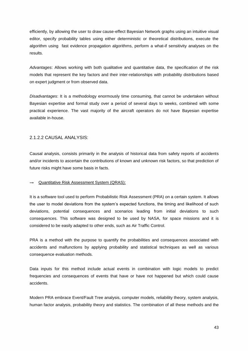
43
efficiently, by allowing the user to draw cause-effect Bayesian Network graphs using an intuitive visual
editor, specify probability tables using either deterministic or theoretical distributions, execute the
algorithm using fast evidence propagation algorithms, perform a what-if sensitivity analyses on the
results.
Advantages: Allows working with both qualitative and quantitative data, the specification of the risk
models that represent the key factors and their inter-relationships with probability distributions based
on expert judgment or from observed data.
Disadvantages: It is a methodology enormously time consuming, that cannot be undertaken without
Bayesian expertise and formal study over a period of several days to weeks, combined with some
practical experience. The vast majority of the aircraft operators do not have Bayesian expertise
available in-house.
2.1.2.2 CAUSAL ANALYSIS:
Causal analysis, consists primarily in the analysis of historical data from safety reports of accidents
and/or incidents to ascertain the contributions of known and unknown risk factors, so that prediction of
future risks might have some basis in facts.
→ Quantitative Risk Assessment System (QRAS):
It is a software tool used to perform Probabilistic Risk Assessment (PRA) on a certain system. It allows
the user to model deviations from the system‟s expected functions, the timing and likelihood of such
deviations, potential consequences and scenarios leading from initial deviations to such
consequences. This software was designed to be used by NASA, for space missions and it is
considered to be easily adapted to other ends, such as Air Traffic Control.
PRA is a method with the purpose to quantify the probabilities and consequences associated with
accidents and malfunctions by applying probability and statistical techniques as well as various
consequence evaluation methods.
Data inputs for this method include actual events in combination with logic models to predict
frequencies and consequences of events that have or have not happened but which could cause
accidents.
Modern PRA embrace Event/Fault Tree analysis, computer models, reliability theory, system analysis,
human factor analysis, probability theory and statistics. The combination of all these methods and the

44
appropriate engineering disciplines are integrated into a formal process that addresses the two
components of risk: likelihood/probability and severity/consequences.
Advantages: It provides a systematic, consistent and coherent framework for estimating risks and
evaluating then before making decisions.
Disadvantages: Application of this software excludes human failure modes, it is limited to hardware.
2.1.2.3 RISK PREDICTION:
Risk prediction tools allow the estimation of the probability of a certain occurrence that will happen,
given a certain set of assumptions. These types of tools differ from Safety Engineering Tools, because
they consider the geometry of the system movement along with time delays and errors in human
responses, contrarily to the latter ones that consider the system as a hardware component.
→ @Risk from Palisade:
It is a quantitative method that represents the outcome of a hazard as a probability distribution. Is a
risk analysis and simulation software tool from Palisade for Microsoft Excel intended to facilitate
quantification and analysis of uncertainty. Provides an iterative process that recalculates spreadsheets
hundreds of times based on the @Risk functions entered. Provides information on what can happen in
a certain situation and how likely it is that it will happen. Probabilities distributions are entered directly
into Excel as a standard worksheet formula, using custom distribution functions, or through myriad
graphical interfaces. For each iteration the spreadsheet is recalculate with a new set of sample values
and a new possible result is generated for output cells – new possible outcomes are generated with
each iteration.
@Risk uses Monte Carlo techniques simulation for the risk analysis, which will be performed in four
steps:
1. Developing the model – defining the scenario in Excel spreadsheet format;
2. Indentify uncertainty – in variables in Excel spreadsheets and specifying their possible
values with probability distributions and identifying the uncertainty spreadsheets results to be
analyzed;
3. Analyzing the Model with Monte Carlo simulations – determine the range of probabilities of
all possible outcomes for the results of the worksheet.
4. Making a decision based on the results provided and personal preferences @Risk helps with
the first 3 steps by providing a powerful and flexible tool that works with Excel to facilitate
model building and Risk analysis.

45
Advantages: Facilitates the quantitative method for assessing the impact of risk decisions and
determining all possible outcomes of a model. Only a basic knowledge of probability theory is
required. And because nowadays most companies and individuals have Excel, @Risk is a valuable
add-in and versatile tool capable of supporting quantitative risk assessment. It is applicable to any
type of hazard: hardware or human related.
Disadvantages: Requires a significant large amount of data, from different experts, for the
development of probabilities distribution for each hazard and a good knowledge of the correlation and
synergy of hazards, in order to produce reliable outputs. Complex systems to be assessed can be
time-consuming.
Several aviation companies are known to be using this software: Northwest Airlines, Cessna Aircraft
Company, Lockheed Martin, Boeing, NASAM Air New Zealand, LOT and US Air Force.
→ Analytical Blunder Risk Model (ABRM):
This 3-D software model estimates the in-air collision risk inherent in a reported (or hypotheticay) air
traffic controller error or pilot deviation. It computes the probability that a particular error will result in
a collision, by calculating the probability of a collision, given a particular error (from controller, pilot or
equipment malfunction) between one aircraft involved in the error and another aircraft. It can assume
two independent scenarios: the probability of a collision occurring with no intervention and the
probability of the timely intervention by pilots or controllers. It uses empirical probability distributions
for reaction times and a closed form probability equation to compute the probability that a collision
will occur.
Advantage: Allows considering combinations of events with small probabilities efficiently and
accurately. Potentially it can be used to compare relative risks between various types of errors in
order to weight the importance of investment in efforts to prevent certain types of errors from
happening.
Disadvantage: Is known to have been used only in theoretical exercises.
→ Traffic Organization and Perturbation Analyzer (TOPAZ):
It is a risk assessment methodology, based on stochastic modeling approach towards risk
assessment and tool set for evaluation of existing or new ATM operational concepts. It accounts for
all types of events (both the nominal and non-nominal) and dynamics of ATM operations, including
interactions between human operators, technical systems and procedures. It facilitates the
quantitative safety assessment and provides safe spacing criticality feedback to developers. The
assessment cycle consists of four steps:

46
1) Identification of operation and hazards.
2) Mathematical modeling.
3) Accident risk assessment.
4) Feedback to operational experts.
Steps 2 and 3 are performed using the following TOPAZ tools:
SIMULATOR: specification and implementation of the mathematical mode and application of
Monte Carlo analysis to the model.
COLLIR: methodology and tool that supports the evaluation of collision risks in the terminal
maneuvering area and en-route.
TAXIR: methodology and tool that supports the evaluation of accident risk at the airport.
CRITER: Risk criteria framework that supports the judgment of the acceptability of the risks
assessed.
Advantages: Dynamic models of non-nominal events. It covers a significant type of hazards and their
correlations.
Disadvantages: It is a very complex system that requires experience from a large number of
disciplines to create new scenarios to risk assess.
This software has developed and has been used since 1992 by NLR in several studies with
EUROCONTROL, European Commission and NASA.
2.1.2.1 RISK ASSESSMENT TOOLS ANALYSIS
All types of risk assessment tools are time consuming and require the participation of different
experiences from subject matter experts, the more the better because the more reliable the results will
be.
Of the three types of risk assessment groups presented, for the purpose of a safety assessment,
which means that a new operation is to be assessed, risk prediction tools is the appropriate group to
use, because:
Safety engineering tools have been developed for the field of reliability engineering and do not
account for the interaction of non-hardware factors, such as human, organizational and
operational factors where historical data is not available. The interdependence of all factors
independently of their type, must be taken under consideration in a safety assessment of a
flight operation.
Causal tools are applied to on-going operations, consequently historical data is available for at
least the majority of the hazards, which for a new operation it isn‟t.
Risk prediction tools allow the estimation of the probability of a certain occurrence that will
happen and takes into account its uncertainty, given a certain set of assumptions. This is
extremely important for the assessment of new operations, which integrates factors from

47
different areas and for each no historical data is available. It uses a probabilistic approach
rather than deterministic and it takes in consideration the interdependence of the different
types of factors present.
For the case of RNP-AR, from the 3 risk prediction tools presented, the @Risk tool, using Monte Carlo
simulations, is considered the more suitable for calculation of the expected risk level. In this case the
risk level will be a probability distribution rather than a deterministic level. This tool is coupled to a well
known tool and readily accessible for all Operators.
The main challenges while using @Risk, is that the hazard likelihood distribution is subjective to the
expertise available therefore, it is important to have a large representation of all integrant areas of the
new operation under safety assessment; development of the hazard scenarios, can be a very
challenging and highly time-consuming task for complex systems.
The reliability of the risk assessment results is highly dependent of the type and quantity of experts,
due to the inexistence of historical data for the hazards, their likelihood of occurrence will be identified
based on individuals judgments. The more judgments, the more data for developing the distributions
and then the higher the confidence level in the results.
2.2 THE RNP CONCEPT
The first ATC system designed, following the ICAO convention used analog radio systems for the
aircraft Communication, Navigation and Surveillance – CNS. Aircraft flew from A to B not in a straight
line, but in the direction of one ground-base navigation aid (NAVAID) and then another - beacons. This
is, flew in a zig-zag trajectory, connecting the dots across the sky until the aircraft would arrive at the
final destination - Figure 9.
Figure 9 – Conventional Instrument Flight Procedure [37]
Ground-base navigation infrastructure aids were used as the sole means to provide pilots with a
navigation capability for all phases of flight. Examples include: Non directional Beacon (NDB), VHF
Omni Directional Radio Range (VOR), Distance Measuring Equipment (DME), Long Range Navigation
(LORAN-C), Inertial Navigation System (INS), Global Navigation Satellite System (GNSS), Microwave
Landing System (MLS), Instrument Landing System (ILS) and Localizer (LOC). Most of these are still
used nowadays, for example [35]:

48
An NDB is a radio station broadcasting an electronic signal on a specific frequency. This device is
unsophisticated and simply provides a crude navigation signal. From a pilot‟s perspective, all it does is
provide a bearing to the signal source. There is no indication of how far an aircraft is from the station
and the only way of knowing is when station passage occurs and the needle reverses direction on the
flight instrument called the Automatic Direction Finder (ADF).
A VOR is a device that provides to the pilot information regarding his position with respect to this
device, through a very high frequency unidirectional radio range. It also provides the pilot with a
bearing to the transmission site that can be integrated into other flight instruments.
A DME is a device that provides the aircraft with a distance (in nautical miles) from its transmitter. This
information if often combined with either the NDB or VOR based position to give both a bearing and
distance to a navigation aid. This provides the pilot with a more complete information of where the
aircraft is.
In the late 60s, a new method of navigation was developed known as RNAV - Area Navigation. It
allowed an aircraft to choose any desired flight path course within coverage of a network of equipment
available, rather than flying directly from beacon to beacon, using waypoints based on radial/DME
from VOR/DME navigation facilities, Figure 10.
RNAV - “A method of navigation that permits aircraft operation on any desired course within the
coverage of station referenced navigation signals or within the limits of a self contained system
capability, or a combination of these. “
Figure 10 – RNAV Procedure [37]
RNAV Advantages:
Flight distance is conserved;
Airspace congestion is reduced, by establishing more direct routes, resulting in shorter
distances → Better use of airspace;
Establishment of dual or parallel routes to accommodate a greater flow of en-route traffic;
Route not tied with fly-over navigation aids → More lateral freedom;
Instrument flight plans started to be used into airports without beacons.
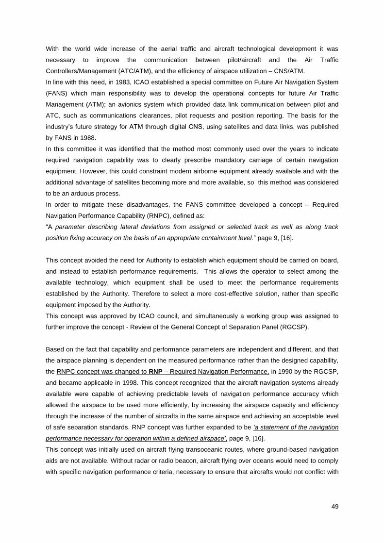
49
With the world wide increase of the aerial traffic and aircraft technological development it was
necessary to improve the communication between pilot/aircraft and the Air Traffic
Controllers/Management (ATC/ATM), and the efficiency of airspace utilization – CNS/ATM.
In line with this need, in 1983, ICAO established a special committee on Future Air Navigation System
(FANS) which main responsibility was to develop the operational concepts for future Air Traffic
Management (ATM); an avionics system which provided data link communication between pilot and
ATC, such as communications clearances, pilot requests and position reporting. The basis for the
industry‟s future strategy for ATM through digital CNS, using satellites and data links, was published
by FANS in 1988.
In this committee it was identified that the method most commonly used over the years to indicate
required navigation capability was to clearly prescribe mandatory carriage of certain navigation
equipment. However, this could constraint modern airborne equipment already available and with the
additional advantage of satellites becoming more and more available, so this method was considered
to be an arduous process.
In order to mitigate these disadvantages, the FANS committee developed a concept – Required
Navigation Performance Capability (RNPC), defined as:
“A parameter describing lateral deviations from assigned or selected track as well as along track
position fixing accuracy on the basis of an appropriate containment level.” page 9, [16].
This concept avoided the need for Authority to establish which equipment should be carried on board,
and instead to establish performance requirements. This allows the operator to select among the
available technology, which equipment shall be used to meet the performance requirements
established by the Authority. Therefore to select a more cost-effective solution, rather than specific
equipment imposed by the Authority.
This concept was approved by ICAO council, and simultaneously a working group was assigned to
further improve the concept - Review of the General Concept of Separation Panel (RGCSP).
Based on the fact that capability and performance parameters are independent and different, and that
the airspace planning is dependent on the measured performance rather than the designed capability,
the RNPC concept was changed to RNP – Required Navigation Performance, in 1990 by the RGCSP,
and became applicable in 1998. This concept recognized that the aircraft navigation systems already
available were capable of achieving predictable levels of navigation performance accuracy which
allowed the airspace to be used more efficiently, by increasing the airspace capacity and efficiency
through the increase of the number of aircrafts in the same airspace and achieving an acceptable level
of safe separation standards. RNP concept was further expanded to be „a statement of the navigation
performance necessary for operation within a defined airspace‟, page 9, [16].
This concept was initially used on aircraft flying transoceanic routes, where ground-based navigation
aids are not available. Without radar or radio beacon, aircraft flying over oceans would need to comply
with specific navigation performance criteria, necessary to ensure that aircrafts would not conflict with

50
each other. RNP could be seen as the evolution of RNAV. This is, an RNAV navigation specification
that includes requirements for on-board performance monitoring and alerting:
“monitoring”: onboard equipment monitors the aircraft‟s performance, in regard of its ability to
determine positioning error and/or to follow the desired path.
“alerting”: the flight crew is alerted if the aircraft‟s navigation system does not perform as
expected.
Specific RNP types are identified by a single accuracy value, RNP - X, that define the navigation
performance, in nautical miles, of the aircraft operating within the airspace appropriate to the
navigation capability. This specifies the navigation performance accuracy of the airspace users and of
the navigation system combinations within the airspace. In practical terms, it contributes to route
definition regarding widths and minimum traffic separation requirements. However, as a standalone
parameter it does not imply or express a separation standard or minima. In order to increase the
confidence level to prevent aircraft conflicts, RNP containment region/limit of an area of 2x RNP-X was
developed. This containment region assures with accuracy, integrity and continuity that the probability
per flight hour of the aircraft position to be within the containment region is 10-5
, equivalent to 99,999%
of flight time.
Each RNP specification establishes the level of onboard equipment required to monitor and alert the
crew, when the RNAV system is not complying with the required performance.
Desired Flight Path
RNP Capability: RNP-X
XX
Whithin bounds 95% of flight time
Whithin bounds 95% of flight time
Containment Limit – 2x RNP-X2X
2XWhithin bounds 99,999% of flight time
Whithin bounds 99,999% of flight time
Figure 11 – RNP Capability and Containment Limit
Each RNP type, this is the system accuracy value known as Navigation Performance Accuracy,
correspond to a total navigation system error (TSE), which is allowed in the horizontal dimension,
including lateral (cross-track) and longitudinal direction (along-track).

51
Figure 12 – Total Navigation System Error – Lateral and Longitudinal Directions [48]
The Total System Error results from a combination of several factors – Figure 13.
Total System Error
Lateral Dimension
(cross - track)
TSE= True position- Centre line of the route flight
programmed
Longitudinal Dimension
(along-track)
TSE= Displayed distance to a specific way-point – True distance
to that point
Navigaton System Error
RNAV Computation Error
Display System Error
Flight Technical Error
Navigation System Error
RNAV Computation Error
Display System Error
POSSIBLE CAUSES
Figure 13 – Total System Error per Dimension
For an aircraft in order to able to navigate with a specific RNP type, both dimensions need to be
evaluated independently, Figure 14 and Figure 15, and in each one the TSE must not exceed the
specified RNP type during 95% of the flight time in any part of any flight, as established by ICAO [16].
Example: RNP 1 – during the approval process for RNP 1, it needs to be proved that the TSE in each
dimension must not exceed the specified RNP type during 95% of the flight in any part of the
flight, this is:
The true position of the aircraft must be within 1 NM of the programmed centre; and
The true distance to way-points must be within 1 NM of the displayed distance to way-points.

52
Figure 14 – System Error – Lateral Dimension (95%) [37]
Figure 15 – System error - Along Track [37]
It is not the purpose of this research to analyze the calculation of the Total System Error. Detailed
description of its calculus is available in ICAO Performance-Based Navigation manual, [38].
The RNP concept is only achievable if both the State and the Aircraft Operator provide the necessary
provisions, this is:
The State must ensure that all necessary CNS services within a specific type of airspace provide
safe separation, and
The Aircraft Operator must ensure that the aircraft is equipped with the appropriate equipment to
the required navigation performance.
Compliance with RNP requirements can be achieved in several ways. Neither the State nor the
Operator is restricted as to how RNP is achieved, as long as it is guaranteed that the requirements are
met.
Since it was first established, the RNP concept has been related to different definitions, with different
levels of performance for different uses. Different types of RNP have been created in order to provide
specific known levels of accuracy for navigation and to support the development of airspace design,
ATC procedures and operational procedures.
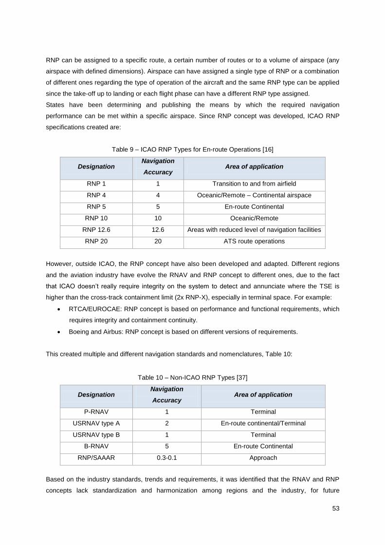
53
RNP can be assigned to a specific route, a certain number of routes or to a volume of airspace (any
airspace with defined dimensions). Airspace can have assigned a single type of RNP or a combination
of different ones regarding the type of operation of the aircraft and the same RNP type can be applied
since the take-off up to landing or each flight phase can have a different RNP type assigned.
States have been determining and publishing the means by which the required navigation
performance can be met within a specific airspace. Since RNP concept was developed, ICAO RNP
specifications created are:
Table 9 – ICAO RNP Types for En-route Operations [16]
Designation Navigation
Accuracy Area of application
RNP 1 1 Transition to and from airfield
RNP 4 4 Oceanic/Remote – Continental airspace
RNP 5 5 En-route Continental
RNP 10 10 Oceanic/Remote
RNP 12.6 12.6 Areas with reduced level of navigation facilities
RNP 20 20 ATS route operations
However, outside ICAO, the RNP concept have also been developed and adapted. Different regions
and the aviation industry have evolve the RNAV and RNP concept to different ones, due to the fact
that ICAO doesn‟t really require integrity on the system to detect and annunciate where the TSE is
higher than the cross-track containment limit (2x RNP-X), especially in terminal space. For example:
RTCA/EUROCAE: RNP concept is based on performance and functional requirements, which
requires integrity and containment continuity.
Boeing and Airbus: RNP concept is based on different versions of requirements.
This created multiple and different navigation standards and nomenclatures, Table 10:
Table 10 – Non-ICAO RNP Types [37]
Designation Navigation
Accuracy Area of application
P-RNAV 1 Terminal
USRNAV type A 2 En-route continental/Terminal
USRNAV type B 1 Terminal
B-RNAV 5 En-route Continental
RNP/SAAAR 0.3-0.1 Approach
Based on the industry standards, trends and requirements, it was identified that the RNAV and RNP
concepts lack standardization and harmonization among regions and the industry, for future

54
operations. As there was no clear distinction of which type of operations required or not on board
monitoring and alerting, based on the designation of the operations.
During the ICAO Global Navigation Satellite System Panel (GNSSP), held on June 3th 2003, a working
group was created in order to act as a focal point for addressing all standardization issues regarding
RNAV and RNP operations – RNPSORSG – Required Navigation Performance Requires Special
Operations Requirements Study Group.
This group recognized the vital need of on-board performance monitoring and alerting requirements as
it was considered of most importance especially in critical flight phases, such as final approach.
However, it was considered that these capabilities would not necessarily be required to satisfy
operational requirements in all types of airspaces and not always within certain airspaces it would be
cost-beneficial. Therefore, it was concluded it would be more beneficial to have a concept focused on
performance based navigation and to develop harmonizing elements for the industry and ICAO
navigation concepts. As a result the Performance Based Navigation (PBN) concept was created. This
concept is applicable to all flight phases, from en-route to terminal and approach areas.
This working group had two main initiatives: harmonization between navigation specifications
nomenclature, based on the monitoring and alerting requirements, between USA/Europe and
development of more capable RNP specifications - Table 11.
Table 11 - Existing Navigation Specifications and New Navigation Specifications [38]
The PBN specifies that for proposed operations within a certain airspace concept, RNAV system
performance requirements, when supported by the adequate navigational aid infrastructure, shall be
defined in terms of:
Accuracy;
Integrity;
Availability;
Continuity;
Functionality.
Under PBN, a navigation specification will either be an RNAV specification or a RNP specification.

55
PBN relies on area navigation systems that include satellite signals with advanced cockpit technology
to fly the aircraft without depending on navigation to/from conventional ground-based navigational
aids. The majority of the navigation systems are already implemented and available however, due to
lack of regulations its use was not possible before.
PBN allows navigation system technology to grow over time without requiring procedures to be
reviewed as long as the navigation performance requirements, such as in the level of accuracy,
integrity, availability, continuity and functionality, for a proposed operation are continuously met by the
navigation system. Benefits of PBN implementation, Figure 16:
Increased airspace safety through implementation of stabilized descent procedures using vertical
guidance;
Fuel savings by reduced track miles and continuous descent profiles;
Fewer denied boarding due to payload restrictions;
Fewer delays and flight diversions;
Lower engine maintenance rate;
Reduced environmental impact through more efficient use of airspace (route assignment, fuel
efficiency and noise abatement);
No need for development of sensor-specific operation for each new evolution of navigation
systems;
More effective aircraft utilization;
More efficient gate utilization;
Introduction of precise and curved paths on the aircraft trajectory - Figure 17;
Figure 16 – PBN Benefits [49]

56
Figure 17 – Flight Path trajectories evolution up to RNP under PBN concept [49]
As mentioned already the ICAO provisions are considered insufficient for terminal airspace
requirements. Following the PBN concept and in line with already existed in the USA, ICAO utmost
development of aircraft operational performance based navigation for approach and missed approach,
using avionics systems where authorization is required, is known as RNP-AR.

57
3 - RNP-AR
Aircraft required navigation performance requirements consist on the optimization of instrument
procedure design based on aircraft required navigation performance – RNP. It allows reducing aircraft
separation en route and in terminal areas to optimize arrival and departures procedures, reducing
operating minima over and above traditional non-precision and conventional RNAV approaches.
As explained in Chapter 2, the RNP concept outside ICAO has evolved into different bases by ICAO
States and Industry, originating some discrepancies between nomenclatures.
Required Navigation Performance – Authorization Requirement (RNP-AR) consists of a new aviation
RNP operational concept. This type of operation requires aircraft qualification, operator approval and
instrument procedures to be designed in order to address the majority of technical and procedure
factors. New operational concepts and its implementation have the potential to contribute significantly
to the safety and efficiency of flight operations. And therefore the safety level is increased.
This utmost development of aircraft operational performance based on navigation performance for
approach, missed approach and departure, using area navigation avionics systems where
authorization is required is known under two different names:
FAA refer to it as RNP SAAAR - Special Aircraft and Aircrew Authorization Required –
published in December 15th 2005 through AC 90-101, [3];
ICAO and EASA refer to it as RNP-AR
o ICAO first introduced this concept in PBN Manual, [37];
o EASA published RNP-AR in Decision 2009/019/R, of 16th December, 2009, amending
the „General Acceptable Means of Compliance of Airworthiness of Products, Parts
and Appliances («AMC-20») – AMC 20-26, [28].
Albeit the requirements established by FAA and EASA are almost identical, the requirements
established by EASA are a little more stringent. This research follows EASA requirements and
guidelines.
The application of RNP-AR procedures to approach and terminal area operations, known as RNP-AR
APCH, is expected to provide an opportunity to utilize current aircraft capability and performance in
order to improve safety, efficiency and capacity through the incorporation of additional navigational
accuracy, integrity and functional capabilities. This allows operations with reduced obstacle clearance
tolerances that enable approach procedures to be implemented in circumstances where other types of
approach and departure procedures are not operationally satisfactory or possible.

58
Figure 18 – RNAV and RN in all phases of the flight [48]
The required navigation specification for this type of approach procedures will only be approved and/or
published where local authorities (NAA, Airport authorities and Navigation Service Providers) consider
that significant operational advantages can be achieved while preserving or improving safety of
operation. Any published RNP-AR procedures will be made available to AOC holders in the State AIP.
Also approach procedures can be private and tailored to AOC holders operational needs, in this case
not available to others operators in the State AIP.
It was not the intention of this research to fully investigate the details that allow the design of a RNP-
AR approach procedure. Therefore only a summary of the main characteristics of RNP-AR
approaches procedures, which differentiate from any other RNP approach, will be provided. Further
guidance and details on procedure design requirements are available in ICAO RNP-AR manual [46].
RNP-AR approach procedures are characterized by:
Narrow lateral linear segments - RNP values ≤ 0.3 NM - Figure 19;
Lower decision altitude/height (DA/H) limits;
Curved segments anywhere along the approach – Radius-to-Fix (RF) legs, Figure 20, before
and after the final approach point. The use of RF legs allows access to airports not previously
available, for example, Bishop airport in California, Figure 21, and contributes to traffic de-
confliction between airports in close proximity, for example JFK and La Guardia airports in the
USA, Figure 22;
Note: RNP-AR Approach procedure charts are depicted in with the the RNAV(RNP)
identification.
Reduced lateral and vertical obstacles clearance surface, Figure 23;
Protections areas laterally limited to 2xRNP value without any secondary buffer - Figure 23
and Figure 24:
o Default values: Lateral TSE of +/- 1 NM in the initial, intermediate and missed
approach segments and TSE of +/- 0.3 NM in the final approach segment;

59
o Lateral TSE as low as +/- 0.1 NM can be require on any segment of the approach
procedure;
o The RNP value should be as high as possible, but low as necessary;
o Vertical accuracy to be maintained as detailed in ICAO PBN Manual, [37] ,volume II,
Chapter 6;
Reduced Vertical Obstacle Clearance (VEB);
Precise missed approach guidance – minima as low as RNP 0.1 on both final approach and
missed approach.
Figure 19 – Differences between Conventional RNP and RNP-AR approach [59]
Currently the majority of airports with published RNP-AR approaches procedures are located in the
USA. In April 2010, 60 airports had published RNP-AR approaches in the USA, such as Chicago, New
York - JFK and La Guardia, Newark, San Francisco, Washington, etc.. However, worldwide new RNP-
AR approach procedures are under approval process and it is expected that in the next coming years
the number airports with public RNP-AR approach procedures and tailored to increase significantly,
especially in Europe. For example: in May 28, 2010, it was officially communicated that Air China had
completed RNP-AR validation flight at Ali airport, in Tibetan Autonomous Region of China, for the
Airbus A310 aircraft, using a tailored RNP-AR procedure; as referred in section 3
2, EASA has made available to some aircraft operators a guidance document, produced by
Eurocontrol on how to conduct a FOSA. This document was developed based on a study made by
Eurocontrol at Bastia and Tromsø airports, where it is planned to implement RNP-AR approaches.

60
Figure 20 – Curved segments – Radius-to-Fix [46]
Figure 21 – Improved access to Bishop Airport [49]

61
Figure 22 – Traffic de-confliction between JFK and La Guardia Airport [49]
Figure 23 – Lateral Protection (plan view): Non RNP-AR vs. RNP-AR. [46]

62
Figure 24 – RNP-AR Segment width and lateral protection (cross section view), [46]
RNP-AR critical component builds on the RNP concept that requires the ability of the aircraft
navigation system to monitor its achieved navigation performance and to identify to the pilot whether
the operational requirement is or is not being met during the operation. This monitoring and alerting is
made available to the pilot through the Flight Management System (FMS) in the flight displays, Figure
25, which computes the aircraft position, based on data from different sensors: Inertial, GPS and radio
navigation (DME and VOR) and computes the Estimated Position Error. Therefore RNP-AR
approaches are only authorized based on GNSS as the primary Navaid infrastructure. The use of
DME/DME as a reversionary capability is only authorized for individual operators where the
infrastructure supports the required performance. RNP-AR operations should not be used in areas of
known navigation signal (GNSS) interference.
Figure 25 – Gulfstream GV-SP (G550) cockpit [27]
Flight Displays
FMS

63
3.1 RNP-AR ADVANTAGES
The main operational benefits of RNP-AR are, Figure 26 and Figure 27:
Additional navigation accuracy, integrity and functional capabilities, by taking advantage of
current aircraft capabilities;
Improved safety level of operations, by replacement of visual procedures or non-precision
approaches, improved situation awareness;
Allows fully automated operation – reduces pilot‟s workload and stress and allows them to
focus on monitoring the flight and react quickly and appropriately in case of an unexpected
event;
Contains the aircraft trajectory in the predefined flight plan;
Better access to terrain-challenged airports and special use airspace. For example Samedan
airport, in mountains terrain in Switzerland, which prevents the installation of ILS;
Enables parallel runway, converging and adjacent airport operations;
Improved access to business airports in proximity to high traffic airports;
Increased airport access in poor weather conditions (low clouds, strong wind, turbulence, etc.);
Increase airport capacity;
Increase airspace capacity by de-conflicting traffic during instrument conditions;
Reduced flight time due to optimized routing;
Smaller environmental footprint due to reduced noise and fuel use;
Enables early, guided turns or missed approach;
Improved efficiency: more reliable, repeatable and optimum flight paths;
The use of RNP-AR can enable accurate navigation and obstacle avoidance in instrument
meteorological conditions (IMC) under the IFR. This can significantly reduce the likelihood of
accidents involving controlled flight into terrain (CFIT). CFIT can be more likely in complex,
non-precision approaches with lack vertical guidance and which impose a high mental work
load on the flight crew.

64
Figure 26 – Benefits of RNP-AR: approaches for parallel, converging and adjacent runways [49]
Figure 27 – Benefits of RNP-AR: Example of a tailored routing [48]
3.2 RNP-AR OPERATIONAL APPROVAL - FOSA REQUIREMENT
RNP-AR approach procedures are accessible to aircraft and operators (AOC holders) that comply with
specific airworthiness and operational requirements, which respective approval has to be requested to
the competent State Aeronautical Authority.
The requirements to obtain operational approval applicable for a European AOC holder are
established in EASA [28] and ICAO‟s PBN [38] and RNP-AR [46] manuals – summary in Table 12.
EASA AMC 20-26, [28] provides means of compliance for applicants for an airworthiness approval to
conduct RNP-AR operations and the applicable criteria to obtain the operational approval. The
operational criteria assumes that the airworthiness approval has already been granted to the aircraft.

65
The authorization process includes approval of Operator‟s operating procedures and crew training
needs. Approval of operating procedures requires the operator to demonstrate to the State Regulator
of Registry, for example for a Portuguese AOC holder this demonstration needs to be done to Instituto
Nacional de Aviação Civil (INAC), that all elements of intended RNP-AR operations have been
appropriately addressed and these include:
1) Determination of aircraft qualification;
2) Training: flight crews, dispatch, etc;
3) MEL, continuing airworthiness;
4) Requirements for operation procedures;
5) Dispatch procedures;
6) Maintenance procedures;
7) Conditions or limitations for approval;
8) Procedure operational validation for each aircraft type, and;
9) Conduct a Flight Operational Safety Assessment (FOSA).
Table 12 – FOSA requirement per regulation source
RNP-AR Manual [46]
1.1.4 Prior to authorization for the conduct of RNP-AR APCH operations an operator must
demonstrate to the State regulator that all appropriate elements of the RNP-AR APCH operations
have been appropriately addressed including:
,…,
i) conduct of a Flight Operational Safety Assessment (FOSA)
1.1.4.6 The specific conditions and issues for these areas are as described in detail in the PBN
Manual.
PBN Manual [38]
6.4.1.1 The safety objective for RNP-AR APCH operations is to provide for safe flight operations.
Traditionally, operational safety has been defined by a target level of safety and specified as a risk of
collision of 10-7
per approach. For RNP-AR APCH a flight operational safety assessment (FOSA)
methodology is used. The FOSA is intended to provide a level of flight safety that is equivalent to the
traditional TLS, but instead using methodology oriented performance-based flight operations. Using
the FOSA the operational safety objective is met by considering more than the aircraft navigation
systems alone. The FOSA blends quantitative and qualitative analyses and assessments for
navigation systems, aircraft systems, operational procedures, hazards, failure mitigations, normal,
rare-normal and abnormal conditions, hazards, and the operational environment. The FOSA relies on
the detailed criteria for aircraft qualification, operator approval and instrument procedure design to
address the majority of general technical, procedural and processing factors. Additionally, technical
and operational expertise and experience are essential to the conduct and conclusion of the FOSA.

66
6.4.1.3 A FOSA should be conducted for RNP-AR APCH procedures where aircraft specific
characteristics, operational environment, obstacle environment, etc, warrant an additional review to
ensure operational safety objectives are still achieved. The assessment should give proper attention
to the interdependence of the elements of design, aircraft capability, crew procedures and operating
environment.
AMC 20-26 [28]
6.1.3 The required demonstration of RNP system performance, including lateral and vertical path
steering performance (FTE), will vary according to the type of AR operation being considered e.g. low
RNP for obstacle clearance or separation in an obstacle rich environment or high density air traffic
environment. It will be for the competent Authority, responsible for the approval of the procedure, to
assess the RNP level for the considered operation in accordance with the Flight Operations Safety
Assessment (FOSA) – Appendix 5.
In supporting the FOSA exercise, the applicant will be required to demonstrate the aircraft capability
in terms of RNP system performance under a variety of operational conditions, rare normal conditions
and non-normal conditions.
For the non-normal conditions the applicant should conduct a safety impact assessment, which
identifies from the existing aircraft System Safety Assessments (SSA), those Failure Conditions that
have an impact on the RNP system performance. This safety assessment should encompass the
additional Failure Conditions introduced by any specific feature designed and implemented and
mitigation for RNP-AR operations (e.g. lateral deviation display) and also identify and document any
additional flight crew procedures and training, necessary to support the overall safety of the
operation, Appendix 5: Exact information as in PBN Manual - section 6.4.
The major difference between European and USA regulation is that the latter does not require the
performance of a FOSA. As per EASA regulation, the AOC holder has to conduct the FOSA to
determine and demonstrate the level of RNP requiring the approval, within the expected environment
of operation, taking into account both normal and abnormal conditions. However, it is unclear in AMC
20-26, [28] if the airline is required to conduct the FOSA even in the conditions where the intended
RNP is higher than the RNP value evaluated and accounted by the manufacturer during the
airworthiness certification.
Analysis of the applicable regulation reveals some inconsistencies:
As per ICAO RNP-AR Manual, [46,] the FOSA is part of the application package for the
operational approval. However, as per AMC 20-26, [28] and PBN Manual the FOSA is only
required to be conducted where the more stringent aspects of the normal procedure are
applied, such as: RF legs after the FAF, RNP missed approaches less than 1.0, RNP final
approaches less than 0.3 or where the operating environment presents specials hazards.

67
In ICAO PBN Manual the safety assessment scope guidance is for the development and
approval of the RNP-AR procedure and not for the Operator to obtain operational approval.
From USA experience, once an operator obtains operational approval, is able to fly all RNP-
AR public procedures. However, ICAO and European regulation are ambiguous in this item.
The European operator shall require a one-time operational approval, valid for all future RNP-
AR procedures or request an approval per each RNP-AR procedure that intends to fly?

68
4 – FOSA METHODOLOGY - THE CASE OF RNP-AR
Due to the lack of guidance available to the public domain and no previous experience and knowledge
to use from USA operators, that already perform RNP-AR (RNP SAAAR) operations, on how to
conduct a FOSA, this research aims to assist European aircraft operators with the compliance of the
FOSA requirement, by providing an acceptable mean of compliance of this requirement.
According to the discussion presented in section 2, of this document, a FOSA methodology should be
no different from a generic safety assessment, once they aim the same objective. This is, a safety
assessment of RNP-AR flight operations. Its objective, as described in EASA AMC 20-26, [28], is the
demonstration of the risk level of this activity and if it meets aimed target level of safety.
As described in section 2 of this document, any type of safety assessment, whether it is to be
performed from the perspective of the Air Navigation Service Provider, Aircraft Operator, Manufacturer
or the Aviation Authority must have per basis the 7 step process safety assessment, Figure 2:
1) System analysis and safety criteria definition
2) Hazards identification
3) Estimation of the hazard(s) consequences severity
4) Estimation of the hazard(s) occurrence likelihood
5) Risk estimation
6) Risk acceptability/mitigation
7) Safety assessment documentation
Because, differences exist on the execution of each of the steps, a safety assessment results from the
combination of methods and/or tools used, for example to identify the hazards and calculate the risk
level. The selection of the methods and tools to use will depend on the system complexity being
assessed and the type of data available.
For the case of safety assessment of RNP-AR flight operations, a failure approach from the
perspective of the aircraft operator is proposed, assuming that in normal conditions the acceptable
level of safety is achieved by compliance of the safety requirements for all the system components.
This is, demonstration of the safety criteria achievement in rare-normal and abnormal conditions is
done by considering what could go wrong and affect the normal system, impair the aimed level of
safety and identify where mitigating actions need to be considered by the operator to reduce the risk
up to the acceptable level.
As referred in AMC 20-26 [28], the FOSA requires the use of a methodology oriented to performance-
based flight operations, where in order to met the safety objective it is necessary to consider
qualitative and quantitative analyses and assessment of the interdependence of navigation and

69
aircraft systems, operational procedures, operational environment, hazards, failure mitigations,
normal and abnormal conditions.
The methodology proposed is intended to be applicable to the following conditions:
Any type of AOC holder requesting the operational approval to perform public RNP-AR approach
procedures. However, examples for a Business Jet operator will be used;
Does not address procedure design and approval. It is considered that if the procedure was
approved, compliance with the safety criteria has been demonstrated;
Does not address aircraft airworthiness certification. It is considered that the Original Equipment
Manufacturer (OEM) has conducted the System Safety Assessment (SSA) necessary to obtain
the airworthiness approval, according to the applicable regulation (e.g. CS-25). Support
documentation from the manufacturer must be obtained for the operational approval request,
describing the aircraft navigation capabilities in the context of RNP-AR operations. A statement in
the AFM (e.g. for the case of the Gulfstream G550 aircraft, in Appendix II) is necessary however
not sufficient;
RNP-AR approach procedures where more stringent aspects of the nominal procedure design
criteria may be applied:
o RNP ≤ 0.3;
o RNP 0.1 missed approach;
o RF legs;
o RNP missed approaches with less than 1.0;
Any aircraft type. However, for the purpose of this research data of the Gulfstream G550 will be
used.
One of the objectives of this research was to apply the proposed methodology to an aircraft operator
undergoing the process of requesting RNP-AR operational approval. Unfortunately due to
unavailability of the operator contacted this was not possible nevertheless, participation and
cooperation from experts from a business jet operator was possible in the hazard identification step.
Therefore a theoretical approach is presented and left to be tested in a forthcoming future.
4.1 STEP 1: SYSTEM AND SAFETY CRITERIA DEFINITION
4.1.1 SYSTEM DEFINITION
In this section a comprehensive description of the flight operation under safety assessment and clear
purpose of the safety assessment, shall be included. This description shall identify all stakeholders for
this operation and respective elements that contribute to RNP-AR approaches.
Section 4 of this document provides a simplified description of RNP-AR approach operations. An
extensive description can be found in ICAO RNP-AR [46] and PBN [37] manuals and EASA AMC 20-

70
26, [28]. The latter also presents the airworthiness and operational approval criteria for this type of
approach.
As depicted in Figure 7, RNP-AR approach operations safety assessment requires input from 3 main
areas: Systems Integrity, Aircraft Operations and Air Navigation Services, which account for all the
RNP-AR requirements to be addressed for the operational approval, Figure 28.
AIRCRAFT
OPERATIONS
AIR
NAVIGATION
SERVICES
SYSTEMS
INTEGRITY
- Aircraft Airworthiness
Approval;
- Aircraft Performance;
- Maintenance Procedures;
- MEL Revision;
- Crew and Dispacth Training;
- Operating Environment;
- Operational Procedures;
- Database Approval;
- ATC Training;
- ATC Procedures;
- Navigation Equipment
Insfrastructures (e.g. GNSS);
Figure 28 – RNP-AR System elements interaction
As per EASA AMC 20-26, [28] in normal conditions, the compliance of all the requirements provides
an acceptable level of safety. Therefore for normal conditions, the FOSA is simplified to demonstration
of compliance of the requirements. However, the FOSA must assess the rare and abnormal conditions
that have the potential to impair the TLS. For this reason, in order to assess the rare and abnormal
conditions it is assumed that:
Aircraft performance is capable of RNP-AR (default conditions) demonstrated by the Type
Certificate holder;
Aircraft Airworthiness certification has been granted to the aircraft type;
Aircraft equipment failure conditions probabilities are provided by the OEI;
Maintenance procedures approved;
MEL revision approved;
Dispatch procedures approved;
Crew and Dispatch training approved;
Approach procedure approved by the Aviation Regulatory Authority;

71
Navigation Database approved;
ATC approval (including training and procedures).
4.1.2 SAFETY CRITERIA DEFINITION
In this section the target level of safety and the criteria against what it is expected to be compared is
presented. Depending on the operation under assessment and the regulation applicable, it can either
be pre-set by the Regulator or set by the Operator, in line with the system definition. Also the criteria
can be quantitative or qualitative.
The objective of the FOSA is to provide evidence that RNP-AR approach operations have been
implemented to be acceptably safe. Demonstration of target level of safety achievement entails
demonstration that the safety criteria is met:
The risk collision per flight /approach ≤ 10-7
the probability of the aircraft exiting the
lateral and vertical extent of the obstacle clearance volume must not exceed 10-7
per flight
hour.
The overall risk of the approach will be lower than the equivalent risk with the „current
operations‟, such as visual approaches and non-precision approaches;
The risk is reduced as far as reasonably practicable.
Because RNP-AR operations are in the terminal airspace area and due to the inherent characteristics
of RNP-AR operations, the underlying safety issues (ARMS definition) to be risk assessed are a mid-
air collision and a control flight into terrain (CFIT). This is, demonstrating that the target safety level is
met, means that the probability of experiencing a mid-air collision and/or a control flight into terrain are
as low as practicable possible and therefore accepted.
This safety criteria encompasses qualitative and quantitative objectives. In order to promote
standardization of criteria and avoid developing one more set risk criteria, CS-25 failure conditions
safety criteria will be used and applied to any type of hazard, either to an equipment failure or a
human or organization failure, Table 13 and Table 14. Minor adjustments were made to the qualitative
probability labeling for clarification purposes, this is:
Extremely Improbable Unlikely
Extremely Remote Rare

72
Table 13 – Hazard consequences severity and probability classification.
Severity Definition Qualitative Probability
Quantitative Probability – Average
probability per flight hour
No Safety Effect
Conditions that would have no effect on safety; that would not affect the operational capability of the aeroplane or increased workload.
No probability requirement
No probability requirement
Minor Conditions which would not significantly reduce aeroplane safety, and which involve crew actions that are well within their capabilities. May include, for example, a slight reduction in safety margins or functional capabilities, a slight increase in crew workload, such as routine flight plan changes, or some physical discomfort to passengers or cabin crew.
Probable Probability > 1x10⁻⁵
Major Conditions which would reduce the capability of the aeroplane or the ability of the crew to cope with adverse operating conditions to the extent that there would be, for example, a significant reduction in safety margins or functional capabilities, a significant increase in crew workload or in conditions impairing crew efficiency, or discomfort to the flight crew, of physical distress to passengers or cabin crew, possibly including injuries.
Remote 1x10⁻⁷
< Prob. < 1x10⁻⁵
Hazardous Conditions, which would reduce the capability of the aeroplane or the ability of the crew to cope with adverse operating, conditions to the extent that would be: i) A large reduction in safety margin or
functional capabilities; iii) ii) Physical distress or excessive workload
such that the flight crew cannot the relied upon to perform their tasks accurately or completely, or;
ii) Serious or fatal injury to a relatively small number of the occupants other than flight crew.
Unlikely 1x10⁻⁹
< Prob. < 1x10⁻⁷
Catastrophic Conditions which would result in multiple fatalities, usually with the loss of the aeroplane.
Rare Probability< 1x10⁻⁹
Due to lack of quantitative data from aircraft operations, it is not possible to assemble quantitative
data from all the 3 main areas, Systems Integrity, Aircraft Operations and Air Navigation Services, the
demonstration that the probability of the aircraft exiting the lateral and vertical extent of the obstacle
clearance volume must not exceed 10-7
per flight hour is achieved by demonstrating that each one of
the potential contributing factors has an „Acceptable‟ level of risk, according to the risk acceptability
criteria. Should any potential hazard have a „Not-acceptable‟ risk, mitigating actions need to implement
to either reduce its likelihood of occurrence or its severity, or preferably reduce both risks‟
components.

73
Table 14 – Risk acceptability criteria
Catastrophic Hazardous Major Minor
Rare
(Probability < 1x10⁻⁹
) Acceptable Acceptable Acceptable Acceptable
Unlikely
(1x10⁻⁹
< Probability < 1x10⁻⁷
) Not acceptable Acceptable Acceptable Acceptable
Remote
(1x10⁻⁷
< Probability < 1x10⁻⁵
) Not acceptable Not acceptable Acceptable Acceptable
Probable
Probability > 1x10⁻⁵
Not acceptable Not acceptable Not acceptable Acceptable
4.2 STEP 2: HAZARDS IDENTIFICATION
The objective of this section is to identify all hazards that can impair the safety level of the operation
under assessment.
Independently of the method and tool used, hazard identification is inherently a subjective task and
hence its effectiveness relies on the expertise of the individual or team analyzing it, especially in the
analysis of new type of operations where operational observations cannot be used. Therefore for new
operations, it is vital that a systematic process is applied in order to assure that all areas of the
operation under assessment are considered.
Because for new operations, there are no observational data/historical records that can be used, a
top-down approach analysis of each one of the sub-systems must be performed, in order to determine
the failures and hazards that can impair each sub-system. This approach shall be performed by a
team – Assessment team, where expertise, available at the AOC holder‟s organization, from each of
the contributing areas is represented, facilitated by an individual who is knowledgeable of safety.
Since RNP-AR approach operations require the participation of several areas and it is necessary to
identify the rare and abnormal conditions that have the potential to impair the safety level of the
operation, it is advisory to gather expertise from each of the 3 areas involved. This team should aim to
answer to the following questions: What can fail? And how it can fail?
From the analysis of the tools available that can assist the execution of this step, the following tools
are identified as the most appropriate to use for new operations:
1) Identification of hazards provided in applicable regulatory documentation: ICAO PBN [37] and
RNP-AR [46] Manuals and EASA AMC 20-26, [28], provide an extensive list of generic hazards for
any type of AOC holder, RNP-AR approaches with RNP ≤ 0.3, to any airport and to any aircraft
type. This exercise should be performed by the facilitator of the assessment team.

74
2) Functional Hazard Assessment brainstorming sessions: This session(s) should focus in identifying
the hazards inherent to the AOC holder, such as organizational hazards and human factors
related to organizational processes directly related to the stakeholders previously identified and to
the specific approach procedure to be flown, which cannot be predicted in the regulatory
documentation due to its individuality, in addition to the generic hazards. This step should be
conducted by a manageable group of experts from the AOC holder which will be involved in the
future operation, if possible expertise from the following areas should be present:
a. Avionics
b. Maintenance procedures / MEL
c. Pilots
d. Dispatch
e. Procedure design
f. Training
g. Standard Operations Procedures
h. Safety – accident/incident investigation
The hazards identified in these sessions are subject to the expertise and experience of each one of
the participants; therefore it is of most importance to have a wide number of areas represented.
This type of brainstorming sessions was not conducted during this research, since no specific airport
approach is under analysis. Detailed information on how to prepare and conduct FHA brainstorming
sessions is available in Eurocontrol SAM manual, [43].
The generic hazards applicable to any RNP-AR approach have been identified based on the analysis
of the regulatory documentation applicable to any RNP-AR. In total 37 generic hazards have been
identified:
Dispatch Hazards:
DIS1) Aircraft dispatched with incorrect RNP assessment
DIS2) Unqualified crew assigned to perform the flight
DIS3) Dispatch failure to identify NOTAMs regarding GPS un-serviceability
Infrastructure Hazards:
INF1) Loss of all navigation information during flight
IINF2) GNSS failure / Loss of GNSS signal during flight
Aircraft Hazards:
A/C 1) Outdated EGPWS database – Nuisance EGPWS warnings/alerts
A/C 2) Outdated navigation database – incorrect cycle (28 days)
A/C 3) Incorrect data/database coding error
A/C 4) Loss of integrity (e.g. RAIM) function (assuming it was available during the pre-flight planning)
– coverage issue
A/C 5) Autopilot failure

75
A/C 6) FMS display failure
A/C 7) FMS total failure
A/C 8) Failure of flight instrument system
A/C 9) Flap retraction problem
A/C 10) Malfunction of air data system or altimetry
A/C 11) Engine failure – One Engine Inoperative
Flight Crew Hazards:
FC1) Incorrect procedure selection or loading in the FMS – Pilot error (e.g. incorrect RNP entry)
FC2) Inadequate reaction to equipment failures
FC3) Erroneous barometric altimeter setting
FC4) Incorrect flight control mode selected – Pilot error
FC5) Poor RNP monitoring
FC6) Poor speed management – excessive speed
FC7) Poor flight crew briefing
FC8) Balked or rejected landing at or below DA/H
ATC Hazards:
ATC1) ATC vectors aircraft onto approach such that performance cannot be achieved
ATC2) Procedure assigned to incapable aircraft
ATC3) Loss of communications
ATC4) Inappropriate altitude clearance
ATC5) Inappropriate separation or sequencing errors
ATC6) Excessive tail wind condition, unexpected before flight planning and take-off
ATC7) Inappropriate speed request for air spacing
ATC8) Inappropriate vectoring
Environment Hazards:
ENV1) Extreme temperature
ENV2) Tailwind above limits
ENV3) Cross wind above limits
ENV4) Severe Turbulence
ENV5) TCAS TA or RA
Throughout the years, the analysis/investigations of aviation accidents/incidents have revealed that an
accident/incident is rarely to occur due to a single factor but rather due to a chain of contributing
factors/hazards/errors. Therefore besides assessing each individual hazard, it is necessary to assess
their synergy and its impact in the severity of the final outcome when compared to the outcome
severity of a standalone hazard occurrence. E.g. Hazard X followed by the occurrence of hazard Y. It
is necessary to analyze the impact of the latter hazard occurrence in the global severity of the
outcome. Will the severity of the consequences resultant from the occurrence of hazard X followed by
the occurrence of hazard Y, be affected due to occurrence of the hazard Y? This is, the severity of
hazard X consequences will increase, reduce or remain the same due to the occurrence of hazard Y?
In order to analyze the synergy between each two hazards, the following matrix was developed -
Figure 29.

76
Figure 29 – Hazard Synergy Matrix
The size of the matrix will be NxN, where N is the number of all individual hazards identified, this is
the generic hazards and the hazards specific to a RNP-AR approach procedure.
The hazard synergy matrix resultant for the RNP-AR generic list of hazards is a 37x37 matrix –
Appendix III.
How to use the Synergy Matrix:
Start reading the matrix in the vertical scale and for each hazard analyze the synergy between its
occurrence followed by the occurrence of each one of the hazards in the horizontal hazard scale. For
each synergy the appropriate impact in the consequences must be selected, this is the impact on the
outcome severity, according to the following criteria:
R – Reduced - Green colour
N – Not impaired/No change in the severity – Yellow colour
I – Increased – Red colour
For example:
The occurrence of hazard 1 accounts for certain consequences and a respective severity.
Assuming the occurrence of hazard 1 is followed by the occurrence of hazard 2, the resultant
consequences and respective severity will increase/decrease or not be impaired due to the
occurrence of hazard 2 when compared to the stand alone severity of hazard 1 occurrence?
If two hazards synergy analysis reveals that the severity will increase this represents a new hazard
and its severity and likelihood must be assessed in addition to the individual hazards. This represents
the potential of assessing an additional number of new hazards to the generic hazards, resultant from
their synergy analysis – Combined hazards. It is assumed that a once a hazard has occurred, the
consecutive occurrence of an identical hazard will not impair the severity of the outcome, as that
severity is already expected to occur since the first manifestation of the hazard.
Assuming all hazards synergy analysis reveal that in all possible combinations the severity increases,
then the number of new hazards identified is:
Combined hazards1st synergy matrix = NN 2
Equation 3 – Combined Hazards
A second hazard synergy and subsequent matrixes have to be performed until the hazards synergies
have reached a status where the operator feels comfortable to disregard consecutive possible
combinations, based on a low likelihood of occurrence. The more complex the combination, the lower

77
the likelihood of the combination to occur. The last possible combination is the one which involves all
the N hazards and its combinations identified:
Total No. Hazards = N + Combined hazards1st synergy matrix + Combined hazards2nd synergy matrix + …
Equation 4 – Total Number of Hazards
Therefore, assuming that the synergy analysis of the 37 generic hazards, reveals that in all synergies
the severity increases, then 1332 hazards need to be analyzed. The synergy of reoccurrence of the
same hazard is excluded.
This means that a safety assessment may require the analysis of an extreme high number of hazards,
resulting in a high-time-consuming and cumbersome manual process.
However, the identification of two or more hazards synergy is not a deterministic process but a very
subjective process, highly dependent of the expertise and experience of the individual performing it.
For this reason, the hazard synergy analysis cannot rely in just one‟s individual analysis, but in the
maximum possible number of experts from all the hazards areas considered. This analysis must be
done by individual and not as a team. The higher number of analysis collected, the higher the
confidence level of the identification of the synergy type.
It was requested to 14 experts from a Business Jet Operator which aims to request RNP-AR
operational approval in a near future, to analyse the synergy of the 37 generic hazards. This group
accounted expertise from the following areas:
Flight Crew – Flight Operations;
Flight Crew Training;
Dispatch;
Maintenance;
Safety (accident/incident investigation expertise);
At the time of production of this report only 4 answers (available in Appendix IV) had been received.
Chart 1 presents the summary of the synergy analysis results per expertise. The different results
substantiate the subjectivity of the hazard analysis process. From the analysis of the results it is
possible to conclude that the hazard synergy identification process is dependent of:
Individual area expertise;
Time available to perform the analysis;
Knowledge of the operation under assessment;
Knowledge of safety/risk assessment processes (especially of what a hazard is);

78
Chart 1 – Number of synergy type per expert
In the absence of identical answers from all key informants and in order to decide ether or not the
synergy needs to be considered as an additional hazard, it is necessary to perform statistical analysis
to the answers received for each possible synergy. An example of an acceptability synergy criteria is
presented – Table 15. This criteria can be customized by the operator.
Table 15 – Synergy criteria for hazard consideration
Severity Increases (I) - % of Answers
≤ 50% of the answers Disregard synergy
> 50% of the answers Consider hazard
For the case of RNP-AR, the statistic analysis of the key informant synergy answers revealed that
from the 1332 possible combinations, 558 synergies (Appendix V) need to be considered - Chart 2.
A total of 595 hazards have to be assessed. Should a different group of experts had been used, then
the result could have been different.
Chart 2 – Number of synergies per percentage of answers that considered „Increased‟ severity

79
The hazards identified in this step are all the conditions that need to be accounted for rare and
abnormal conditions and that have the potential to impair the TLS.
4.3 STEP 3: HAZARD SEVERITY ESTIMATION
Following the identification of the number of hazards that need to be considered, each one must be
analysed in order to identify what is/are its potential consequences and classify its severity according
to the risk classification criteria - Table 14. A proper assessment of the hazard consequences requires
the consideration of the one of the concepts highlighted by ARMS work - recoverability, i.e. once a
hazard occurs what is currently in place to recover from the potential consequence, worst case
scenario a catastrophic accident.
Due to the hazards nature, its analyses is divided it in two main groups:
1) Aircraft Failure Hazards – These failures had to be considered during the aircraft airworthiness
certification therefore the severity should be extracted from the regulatory documentation or
from the supporting documentation to be provided by the OEM, once it was responsible for
conducting the SSA for the airworthiness approval. This is a straight forward analysis, with no
margin for interpretations from operator to operator. Obtaining this information from the
manufacturer may be the main challenge.
2) Human Factors and Environment Hazards – No previous information or classification is
available regarding these types of hazards, except the overall acceptance that they do
constitute a potential hazard to the operation. Therefore the analysis of these types of
hazards is subjective to the individual knowledge and experience because it is very difficult to
accurately identify a single severity classification due to the lack of quantitative data. For this
reason, the following approach is proposed:
a. Brainstorming sessions with experts, who have participated in step 2. The aim of
these brainstorming sessions is to identify the potential consequences of each hazard
and its classification in terms of severity, according to the risk acceptability criteria.
Once more it is highly advantageous to have experts from all the areas under
consideration. Depending on the expert group‟ analysis per hazard one or multiple
severities will be identified for each hazard.
Due to the lack of availability from experts to participate in this step, it was not possible to perform it.
It is very common in the aviation industry to use a hazard log to record each of the hazard
analysis. Here it is called Safety Assessment log and is to be constituted by several modules,
respectively from each step of the safety assessment process. Three examples of hazard
severity analysis are provided for an aircraft failure hazard and for a human factor - Table 16.

80
Table 16 – Severity Analysis (examples)
Hazard FMS display failure
Consequences The crew looses the capacity of monitoring the aircraft position.
Looses the capacity of monitoring deviations.
Current recoverability defence(s) Abandon the RNP approach and divert if possible.
Severity Major
Hazard Erroneous barometric altimeter setting
Consequences Deviation from intended flight track and inadequate monitoring
of aircraft position.
Current recoverability defence(s) Radio altimeter cross–checks at a certain altitude as per
Standard Operating Procedures.
Severity Major
Hazard Loss of navigation database
Consequences Vertical and/or lateral deviation from the intended flight track.
Loss of obstacle and terrain clearance
Current recoverability defence(s) Visual obstacle and terrain clearance.
Severity Catastrophic or Hazardous
4.4 STEP 4: HAZARD LIKELIHOOD ESTIMATION
The performance of this step is no different from step 3. Except that the object of analysis is the
likelihood of occurrence of the hazard consequences, according to the risk classification criteria -
Table 14.
Also due to the hazards nature, its analyses is divided it in two main groups:
1) Aircraft Failure Hazards – These failures had to be considered during the aircraft airworthiness
certification therefore the likelihood should be extracted from the regulatory documentation or
from the supporting information provided by the manufacturer. This must be a straight forward
analysis extracted from the SSA, with no margin for different analysis from operator to
operator.
2) Human Factors and Environment Hazards - The analysis of these types of hazards is
subjective to the individual knowledge and experience because it is very difficult to accurately
identify a single likelihood classification due to the uncertainty of occurrence, lack of previous
knowledge and historical records from this operation and therefore lack of quantitative data.
For this reason, the brainstorming sessions referred in step 3, should address the
identification of the two risk components.
RNP-AR operations depend highly on airplane systems for integrity but, the main challenge when
performing the RNP-AR safety assessment is the relationship between the airplane systems and the
human interactions/human error. Furthermore the latter is in fact the larger contributor to the
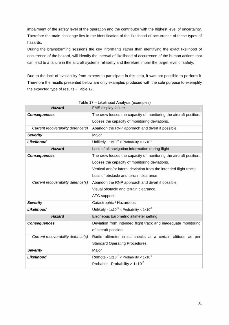
81
impairment of the safety level of the operation and the contributor with the highest level of uncertainty.
Therefore the main challenge lies in the identification of the likelihood of occurrence of these types of
hazards.
During the brainstorming sessions the key informants rather than identifying the exact likelihood of
occurrence of the hazard, will identify the interval of likelihood of occurrence of the human actions that
can lead to a failure in the aircraft systems reliability and therefore impair the target level of safety.
Due to the lack of availability from experts to participate in this step, it was not possible to perform it.
Therefore the results presented below are only examples produced with the sole purpose to exemplify
the expected type of results - Table 17.
Table 17 – Likelihood Analysis (examples)
Hazard FMS display failure
Consequences The crew looses the capacity of monitoring the aircraft position.
Looses the capacity of monitoring deviations.
Current recoverability defence(s) Abandon the RNP approach and divert if possible.
Severity Major
Likelihood Unlikely - 1x10⁻⁹
< Probability < 1x10⁻⁷
Hazard Loss of all navigation information during flight
Consequences The crew looses the capacity of monitoring the aircraft position.
Looses the capacity of monitoring deviations.
Vertical and/or lateral deviation from the intended flight track;
Loss of obstacle and terrain clearance
Current recoverability defence(s) Abandon the RNP approach and divert if possible.
Visual obstacle and terrain clearance.
ATC support.
Severity Catastrophic / Hazardous
Likelihood Unlikely - 1x10⁻⁹
< Probability < 1x10⁻⁷
Hazard Erroneous barometric altimeter setting
Consequences Deviation from intended flight track and inadequate monitoring
of aircraft position.
Current recoverability defence(s) Radio altimeter cross–checks at a certain altitude as per
Standard Operating Procedures.
Severity Major
Likelihood Remote - 1x10⁻⁷
< Probability < 1x10⁻⁵
Probable - Probability > 1x10⁻⁵

82
4.5 STEP 5: RISK ESTIMATION
The main challenge of the safety assessment is the calculation of the risk level and demonstration that
the safety criteria is achieved, this is, the calculation of the risk index for each one of the hazards
identified.
As identified in step 4, for non aircraft failures a single or multiples several classifications were
identified per approach; the same occurs for the likelihood of occurrence, where an interval(s) of
occurrence was identified - both risk components results can be represented as probability
distributions. Therefore the risk analysis will output a range of possible risk levels, instead of a single
value. Consequently a high degree of uncertainty is present for these types of hazards regarding their
severity and likelihood of occurrence. Table 18 for example.
Table 18 – Risk estimation (examples)
Hazard Loss of all navigation information during flight
Consequences The crew looses the capacity of monitoring the aircraft position.
Looses the capacity of monitoring deviations.
Vertical and/or lateral deviation from the intended flight track;
Loss of obstacle and terrain clearance
Current recoverability defence(s) Abandon the RNP approach and divert if possible.
Visual obstacle and terrain clearance.
ATC support.
Severity Catastrophic / Hazardous
Likelihood Unlikely - 1x10⁻⁹
< Probability < 1x10⁻⁷
Current Risk „Not acceptable‟ and „Acceptable‟
Hazard Loss of all navigation information during flight (INF1) x
Erroneous barometric altimeter setting (FC3)
Consequences The crew looses the capacity of monitoring the aircraft position.
Looses the capacity of monitoring deviations.
Vertical and/or lateral deviation from the intended flight track.
Loss of obstacle and terrain clearance.
Incorrect speed and altitude information.
Current recoverability defence(s) Abandon the RNP approach and divert if possible.
Visual obstacle and terrain clearance.
ATC support.
Severity Catastrophic
Likelihood From INF1:
- Unlikely - 1x10
-9 < Probability < 1x10
-7
From FC3:
- Remote - 1x10
-7 < Probability < 1x10
-5

83
- Probable - 1x10⁻⁵
< Probability < 1
Synergy likelihood: Rare / Unlikely
Current Risk „Acceptable‟ and „Not acceptable‟
The results of the risk analysis per hazard shall be recorded in the Safety Assessment Log, similar to
the previous safety assessment steps.
According to the risk classification criteria the risk of „Loss of all navigation information during flight‟ is
uncertain, it can either be „Not acceptable‟ or „Acceptable‟.
As already referred the purpose of the safety assessment is to identify the safety level associated to a
specific action/operation through the identification of the expected risk(s), by providing guidance to the
decision-making roles in order to either accept or not the risk(s) to which the operation is expected to
be exposed. So, what should be decided regarding this hazard‟s risk level? Is the information provided
sufficient to support the decision making-process? Two approaches can be used in order to answer to
these questions:
A conservative approach, this is, select the higher risk level obtained. If „Not Acceptable‟,
implement corrective measures and reassess the residual risk until it achieves an acceptable
level. Disadvantages of this approach are related to unnecessary costs and business
implications.
Obtain complementary information to support the risk decision making process, in order to
ensure a higher confidence level when deciding the risk level. This is only possible through
the use of a different risk estimation method. Due to the variability and uncertainty of the
parameters, severity and likelihood, a probabilistic approach can be used. Additionally due to
the high number of hazards to be analyzed, it becomes an arduous task to perform the risk
estimation manually. It is therefore advantageous the use of a mathematical tool to support
the risk analysis process, by facilitating the quantitative method for assessing the impact of
risk decisions and determining all possible outcomes for each hazard.
Based on the tools presented in section 2, it is recommended the use of @Risk from Palisade to
support the risk analysis and decision making process regarding risk acceptability or not. This
software uses Monte Carlo techniques simulation to provide an iterative process that recalculates
spreadsheets hundreds of times based on the @Risk functions entered. Provides information on what
can happen in a certain situation and how likely it is that it will happen. Probabilities distributions are
entered directly into Excel as a standard worksheet formula, using custom distribution functions, or
through myriad graphical interfaces. For each iteration the spreadsheet is recalculate with a new set of
sample values and a new possible result is generated for output cells – new possible outcomes are
generated with each iteration.
The use of this tool addresses 3 steps:
1) Definition of the model (for each hazard): Risk = Severity x Probability;

84
2) Identification of the uncertainty – in variables in Excel spreadsheets and specifying their
possible values with probability distributions, and identifying the uncertainty spreadsheets
results to be analyzed;
3) Analyzing the Model with Monte Carlo simulations – determine the range of probabilities of
all possible outcomes for the results of the worksheet.
Nevertheless, extrapolating data from statistic rare events must be done with great care, because if it
fails to account important factors or excessive conservative assumptions are made, requirements may
increase up to the point where potential safety and operational benefits are unbalanced.
The use of @Risk tool is only advantageous if assessing a large amount of the data, unfortunately due
to unavailability of participation of experts from the operator contacted, it was not possible to gather
this data and consequently the use of @Risk was not tested.
4.6 STEP 6: RISK ACCEPTABILITY
Once the risk level or distribution is estimated, it needs to be compared to the pre-set target level of
safety by regulations and to the safety criteria used - Table 14. Should the risk fall within the non-
acceptable range, operation must not commence prior to the implementation of mitigating measures
and reassessment of the residual risk until it achieves an acceptable level.
4.7 STEP 7: SAFETY ASSESSMENT DOCUMENTATION
The prime driver of the need to perform a FOSA is the demonstration to the Aviation Authority that the
safety requirements are met. Therefore it is extremely important that all safety assessments steps are
properly recorded and made available to the Aviation Authority. A Safety Assessment Log shall
compile the results from steps 2 to 6.
4.8 MONITORING PROPOSAL
As per AMC 20-26, [28], the operational approval requires the aircraft operator to implement a RNP-
AR monitoring programme to ensure continued compliance with the guidance provided by collecting
data periodically and analyse it in order to identify any negative safety concerns and trends in
operational performance, for a minimum period of 90 days – considered an interim approval period.
This data shall be sent every 30 days to the Civil Aviation Authority.
The main purpose of this monitoring program is to assess the current safety level of the operations
and if additional mitigating measures are necessary to reduce the risk up to an acceptable level.
The information to be collected is:
1) Total number of RNP-AR procedures conducted.

85
2) Number of satisfactory approaches by aircraft/system. It is considered satisfactory if it was
completed as planned without any navigation or guidance system anomalies.
3) Reasons for unsatisfactory approaches, such as:
a. „UNABLE REQ NAV PERF‟, „NAC ACCUR DOWNGRADA‟, or other RNP messages
during approaches
b. Excessive lateral or vertical deviation
c. TAWS warning
d. Autopilot system disconnect
e. Navigation data errors
f. Pilot report of any anomaly
4) Crew comments
Based on this requirement, AOC holders can establish their monitoring program using one or two
sources of information:
The use of a RNP-AR Monitoring Form that shall be filled by the crew after each RNP-AR
approach procedure completed. The data collect through this form shall be systematically
analysed in order to identify any negative trends related to the procedure performance. The
safety reporting system, as required by EU-OPS 1.420 and hazard identification methods
used by AOC holder are considered appropriate mechanisms for the data collection and
respective analysis. Appendix VI presents a form proposal, or
Flight data analysis, through the Flight Data Monitoring (FDM) program. This source of
information provides more accurate and realistic data. However, once this is only mandatory,
per EU-OPS 1.037, to have in place for aircrafts with a maximum take-off mass higher than
27000kg, some AOC holders may not have this program in place and its implementation
requires a significant financial investment. Cost benefit analysis to be performed regarding its
implementation or not. Nevertheless flight data can also be obtained by download of FDR
data after each flight.

86
5 – CONCLUSIONS AND RECOMMENDATIONS
Conclusions
The purpose of this research was to provide an understanding of the FOSA requirement, stated in
EASA AMC 20-26, [28], necessary to be conducted by an aircraft operator in order to be granted
RNP-AR operational approval and propose a practical approach towards this requisite‟s compliance.
The objective of the „FOSA methodology‟ is clearly extracted from the applicable regulation:
demonstrate that the acceptable level of safety for RNP-AR operations is met, i.e. that the probability
of risk of collision is less than 10-7
per flight or approach. However, no official documentation produced
or supported by ICAO or EASA is available to the public domain regarding what a FOSA methodology
is. How can the aircraft operator demonstrate that the target level of safety is achieved?
The first question this research tried to answer was: What is a FOSA methodology? Investigation
revealed that safety assessment and risk assessment expressions are widely used in the aviation
industry across the world as processes to assess the safety and/or risk level of operations, but there is
a lack of terminology standardization and understanding regarding these two approaches and their
differences. Many differences have also been identified regarding safety and risk definitions. For the
purpose of this research and to promote standardization it is selected to use the ICAO definition.
Analysis of the different meanings for safety and risk assessment used by different stakeholders
revealed that none of them intends to be prescriptive, rather to provide guidance regarding acceptable
methods that can be adopted and adapted to systematically manage safety in a rational and thoughtful
way, independently of the environment being assessed. These two approaches share the same
purpose and goal and what sets the distinction between the two is their applicability, i.e. a safety
assessment is applied to a new system/operation/process while risk assessment is applied to a known
or on-going operation. Additionally a risk assessment is an integrant part of a safety assessment,
because once an operation is put in place, the safety level must be oversight and systematically
managed respectively by risk assessment and risk management.
If a safety assessment and a FOSA share the same objective, i.e. demonstrate that the acceptable
level of safety of an operation is met (target level of safety, as per EASA AMC 20-26, [28]), according
to a pre-set safety criteria, and both are to be applicable to a new operation, than a FOSA
methodology should be no different from a generic safety assessment methodology, having per basis
the 7 step process safety assessment widely accepted at the aviation industry.
1) System analysis and safety criteria definition
2) Hazards identification
3) Estimation of the hazard(s) consequences severity
4) Estimation of the hazard(s) occurrence likelihood

87
5) Risk estimation
6) Risk acceptability/mitigation
7) Safety assessment documentation
The safety assessment shall result from the combination of methods and/or tools used for each of the
steps. Three steps drive the safety assessment: hazard identification, hazard severity identification
and hazard likelihood estimation. The methods and tools used for each one set the difference between
safety and risk assessments available in the public domain. All types of tools analyzed are time
consuming and require the participation of subject matter experts, the more the better as the more
reliable the results will be. It is concluded that independently of the tools selected, safety and risk
assessment will always be a subjective assessment, highly dependent of the expertise of the
participants, due to the inexistence of historical data for the hazards, their likelihood of occurrence will
be identified based on individuals judgments. The larger the representation the better because, more
data will be available for identifying the distributions and then the higher the confidence level in the
results is.
For the execution of the three main steps and in order to benefit from the resources, experience and
expertise available at the majority of the aircraft operators, from a practical and finance perspective,
for the case of RNP-AR the use of key informant technique, brainstorming sessions and Excel
software from Microsoft was selected.
Because an accident rarely occurs due to a single factor but rather due to a chain of contributing
factors/hazards/errors, besides assessing each individual hazard, it is necessary to assess their
synergy and its impact in the severity on the final outcome when compared to the outcome severity of
a standalone hazard occurrence. In order to assist this step the concept of „Hazard Synergy Matrix‟
was created.
Another challenge identified for the case of RNP – AR is the establishment of a numerical relationship
between the probability of occurrence between the hazards resultant from the airplane systems
integrity, air navigation services and the human interactions/errors, due to lack of quantitative data
from aircraft operations. Furthermore the latter is in fact the larger contributor to the impairment of the
safety level of the operation and the contributor with the highest level of uncertainty. Therefore the
main challenge lies in the identification of the likelihood of occurrence of these types of hazards. The
demonstration that the probability of the aircraft exiting the lateral and vertical extent of the obstacle
clearance volume must not exceed 10-7
per flight hour is achieved by demonstrating that each one of
the potential contributing factors has an „Acceptable‟ level of risk, according to the risk acceptability
criteria. Should any potential hazard have a „Not-acceptable‟ risk, mitigating actions need to implement
to either reduce its likelihood of occurrence or its severity, or preferably reduce both risks‟
components.
88
Because the safety assessment steps that drive the safety assessment are dependent of expertise
inputs and consensus most probably will not be achieved between all the participants and due to the
high number of hazards, it becomes an impractical task to perform the risk estimation manually. Due
to the variability and uncertainty of the parameters, severity and likelihood, a probabilistic approach
must be used. It is therefore advantageous the use of a mathematical tool to support the risk
estimation process, by facilitating the quantitative method for assessing the impact of risk decisions
and determining all possible outcomes for each hazard. The use of @Risk, from Palisade, is
recommended to support the risk analysis and decision making process regarding risk acceptability or
not.
Hence it is concluded that a safety assessment of an aircraft operation:
Requires the use of a methodology oriented to performance-based, where in order to meet the
safety objective it is necessary to consider qualitative and quantitative analyses and
assessment of the interdependence of all potential hazards from all areas, namely navigation
systems, aircraft systems, operational procedures and operational environment. The hazard
synergy matrix assists in the interdependence analysis.
Must balance between probabilistic and qualitative assessment.
Independently of the tools used for each step, will always be a subjective methodology, highly
dependent of the expertise and knowledge of those participating in the safety assessment.
The negative impact of this subjectivity can only be reduced through a good representation of
all the areas involved in the operation.
It is impractical to develop a safety assessment method that fits all objects of assessment,
such as all aircraft operations, all aircraft types, all airspace users, all navigation users, etc..
It is important to understand that a safety assessment tool itself does not guarantee a safe operation.
It is only an additional tool to help the Aircraft Operator and the Aviation Regulatory Authority to make
sound safety decisions in order to demonstrate that the safety criteria is met. Operational safety is a
shared responsibility between all stakeholders.
Recommendations for further improvement:
Test the effectiveness and practicality of each FOSA‟s step proposed and not tested, including
the use of @Risk software from Palisade, on an aircraft operator undergoing the process of
requesting RNP-AR operational approval.
Aviation Regulators should promote standardization and harmonization of nomenclature and
processes regarding safety and risk assessment and avoid the creation of new methodology
names, which aim the same goals as from those of existent generic approaches, without
clearly explaining what is expected to be done. This standardization should also address risk
definition.

89
EASA should provide guidance to Civil Aviation Authorities regarding the acceptable means of
compliance for the FOSA requirement. The current ambiguity has the potential to result in
different Civil Aviation Authorities approving their aircraft operators under different methods to
demonstrate safety compliance, resulting in a potential exposure to unacceptable levels of
safety in some airspace.
As per ICAO RNP-AR Manual, the FOSA is part of the application package for the operational
approval. However, as per AMC 20-26, [28] and PBN Manual the FOSA is only required to be
conducted where the more stringent aspects of the normal procedure are applied, such as: RF
legs after the FAF, RNP missed approaches less than 1.0, RNP final approaches less than 0.3
or where the operating environment presents specials hazards. EASA shoul clarify the
conditions when the execution of a FOSA is necessary.
Manufactures must assist the Aircraft Operators in the operational approval request by
providing documentation regarding the system safety assessment conducted at the time of the
airworthiness approval.
From USA experience, once an operator obtains operational approval, is able to fly all RNP-
AR approved procedures. However, ICAO and European regulation are ambiguous in this
item. EASA must clarify in AMC 20-26, [28], if a European operator shall require a one-time
operational approval, valid for all future RNP-AR procedures or request an approval per each
RNP-AR procedure that intends to fly and consequently what are conditions where the FOSA
is required.
Because conventional risk assessment methodologies have significant limitations, a practical
and user friendly methodology, balancing between numeric and qualitative assessment must
be developed for operations that depend highly of airplane systems integrity and human
interaction.
Although the method used in this research to obtain intervals of likelihood of occurrence for
human related hazards results in a numeric interval and the process to achieve it is extremely
subjective. It is recommended to test the use of another approach to quantify the probabilities
of human error rate. A well accepted method is the Technique for Human Error Rate
Prediction (THERP).
Due to the inherent subjectivity and identified limitations of safety and risk assessment
techniques and to the specificities of this new type of RNP operation, is important that Aviation
Regulators should promote a strategy for an active sharing of experience, knowledge and
information between all stakeholders and operators involved in RNP-AR operations. It is
precisely for this reason that the monitoring is so critical.

90
6 – BIBLIOGRAPHY
[1] Federal Aviation Administration [FAA] (2000). Use of Barometric Vertical Navigation (VNAV)
for Instrument Approach Operations Using Decision Altitude (AC 90-97), October 19th, USA
[2] Federal Aviation Administration [FAA] (2007). U.S. Terminal and En Route Area Navigation
(RNAV) Operations (AC 90-100A), March 1st, USA
[3] Federal Aviation Administration [FAA] (2005). Approval Guidance for RNP Procedures with
Special Aircraft and Aircrew Authorization Required (AC 90-101), December 15th, USA
[4] Federal Aviation Administration [FAA] (2006). Introduction to Safety Management Systems for
Air Operators (AC 120-92), June 22th, USA
[5] Federal Aviation Administration [FAA] (2003). Developing and Implementing a Continuing
Analysis and Surveillance System (AC 120-79), April 21st,USA
[6] Federal Aviation Administration [FAA] (2004). Flight Operational Quality Assurance (AC 120-
82), April 12th
, USA
[7] Federal Aviation Administration [FAA] (2007), Flight Risk Assessment Tool (Info 0701), March
7th, USA
[8] European Aviation Safety Agency [EASA] (2008). Airworthiness and Operational Approval for
On Board Equipment Related to Required Navigation Performance/Area
Navigation(RNP/RNAV) Approach Operations (NPA.14.2008), May 26th, Köln, Germany
[9] International Civil Aviation Organization [ICAO] (2007). Procedures for Air Navigation Services
– Air Traffic Management, 15th edition (Doc. 4444), Montreal, Canada
[10] International Civil Aviation Organization [ICAO] (2008). Regional Supplementary Procedures,
5th
edition, (Doc. 7030), Montreal, Canada
[11] International Civil Aviation Organization [ICAO] (1994). Aeronautical Chart Catalogue,1st
edition (Doc. 7101), Montreal, Canada
[12] International Civil Aviation Organization [ICAO] (2003). Aeronautical Information Services
Manual, 6th edition, (Doc. 8126), Montreal, Canada
[13] International Civil Aviation Organization [ICAO]. Volume I – Flight Procedures, (Doc 8169),
Montreal, Canada
[14] International Civil Aviation Organization [ICAO] (2004). ICAO Abbreviations and Codes, 6th
edition (Doc 8400), Montreal, Canada
[15] International Civil Aviation Organization [ICAO] (2009). Safety Management System, 2th
edition (Doc 9859), Montreal, Canada
[16] International Civil Aviation Organization [ICAO] (1999). Manual on Required Navigation
Performance, 2nd
edition, (Doc 9613), Montreal, Canada
[17] Reason J. (2002), Managing the Risks of Organizational Accidents, Ashgate

91
[18] Stamatelatos, Dr. Michael. Probabilistic Risk Assessment: What is and Why is it worth
performing it?, Retrieved May 2009 at 17:59 from
http://www.hq.nasa.gov/office/codeq/qnews/pra.pdf
[19] Andrews J.D., Moss T.R. (2002) Reliability and Risk Assessment, 2nd
edition, Professional
Engineering Publishing
[20] Boeing, Air Traffic Alliance (2005), Air Traffic Alliance – Boeing Required Navigation
Performance Joint Position, Retrieved on September 17th, 2009. from
http://www.ecacnav.com/downloads/4.1%20Boeing%20Air%20Traffic%20Alliance%20joint.pdf
European Aviation Certification Specification [EASA] (2009), Certification Specifications for
Large Aeroplanes CS-25 (Annex to ED Decision 2009/017/R), Amendment 8, December 18th
[21] Boeing (2000), Required Navigation Performance (RNP) and Area Navigation, August
[22] Koller, Glenn (2005). Risk Assessment and Decision Making in Business and Industry, 2nd
edition, Chapman & Hall/CRC
[23] Stolzer, Alan J., Halford, Carl D., Goglia, John J.(2008) Safety Management Systems in
Aviation, 1st edition, Ashgate
[24] Flight Safety Foundation (2003). Guide to Methods & Tools for Airline Flight Safety Analysis,
2nd
edition, June
[25] Flight Safety Foundation (2003). Guide to Methods & Tools for Safety Analysis in Air Traffic
Management, 1st edition, June
[26] http://en.wikipedia.org/wiki/Future_Air_Navigation_System, Retrieved on April 5th, 2009 at
12:11 (UTC+1)
[27] Honeywell (2009). C&PS Flight Operations - Primus Certification, USA
[28] European Aviation Safety Aviation [EASA] (2009). AMC 20-26, Airworthiness Approval and
Operational Criteria for RNP Authorization Required (RNP-AR) Operations (ED Decision
2009/019/R),December 16th, Köln, Germany
[29] International Civil Aviation Organization [ICAO] (2008). Guidance material on required
navigation performance authorization required (RNP-AR) procedure design (State Letter
08.58), Montreal, Canada
[30] Federal Aviation Administration [FAA] (2205). United States Standard for Required Navigation
Performance (RNP) Approach Procedures with Special Aircraft and Aircraft and Aircrew
authorization required (Order 8260-52), June, USA
[31] International Civil Aviation Organization [ICAO] (1994). Facts about ICAO, (Order No.
3120023A), Montreal, Canada
[32] http://www.ecacnav.com/PBN, Retrieved on July 16th, 2009, at 23:11 (UTC+1)
[33] http://www.airlines.org, Retrieved on July 17th, 2009 at 00:04 (UTC+1)
[34] JetPro Canada. Conventional Navigational Aids, Retrieved July 27, 2009 at, 17:59 from
http://www.jetpro.ca/Article%202.html
[35] International Civil AviationI Organizatio [ICAO], Eurocontrol (2009). RNP RNAV – A Global
Navigation Concept, Retrieved from http://www.ecacnav.com/downloads/YCoutier%20-
%20RNP%20RNAV.pdf on July 26th at 17:17 (UTC+1)
92
[36] Airbus - Flight Operations Support and Services (2008). Getting to Grips with RNP-AR, May,
France
[37] International Civil Aviation Organization [ICAO] (2008). Performance-Based Navigation
Manual, 3rd
Edition. (Doc.9613). Montreal, Canada
[38] International Civil Aviation Organization [ICAO] (2006). Heading for Performance based
Navigation (14th SIIV IFIS Conference Preceding), June 12-16
th, France
[39] Airline Risk Management Solutions [ARMS] (2009). Operational Risk Assessment – Next
Generation Methodology, Retrieved from http://www.skybrary.aero/bookshelf/books/694.pdf (
on September 13th at 15:39 (UTC+1)
[40] International Civil Aviation Organization [ICAO] (2006). Safety Management System Manual,
1st edition, (Doc. 9859), Montreal, Canada
[41] UK Civil Aviation Authority [CAA] (2006). Guidance on the Conduct of Hazard Identification,
Risk Assessment and the Production of Safety Cases – For Aerodrome Operators and Air
Traffic Service Providers (CAP 760), January, UK
[42] UK Civil Aviation Authority [CAA] (2003), The Management of Safety – Guidance to
Aerodromes and Air Traffic Service Units on the Development of Safety Management
Systems (CAP 728), March, UK
[43] Eurocontrol (2010). Safety Assessment Made Easier – Part 1: Safety Principles and an
Introduction to Safety Assessment , 1st edition, January
[44] Eurocontrol (2010). Guidance Material on Flight Operational Safety Assessment (FOSA) for
RNP Applications, (Working draft) Edition. 0.3, January
[45] Transport Canada (2001). Pilotage Risk Management Methodology (TP13741E), 2001,
Canada
[46] International Civil Aviation Organization [ICAO] (2009), Required Navigation Performance
Authorization Required (RNP-AR) Procedure Design Manual, Advanced Edition (Unedited)
(Doc 9905), Montreal, Canada
[47] Oxford Aviation Training (2007). Navigation, OATmedia
[48] Bill Dunlay, Leigh Fisher Associates (2006), Near Term Potential for System Capacity Gains
from RNP and RNAV procedures, (Asilomar Conference Preceding), March
[49] Honeywell (2010), RNP SAAR Pilot Training Gulfstream (350/450/500/550), (RNP-AR
Training Course at INAC), June, Portugal
[50] International Civil Aviation Organization [ICAO], Aircraft Accident and Incident Investigation,
9th Edition, (Annex 13), Montreal, Canada

93
APPENDIX I
International Civil Aviation Authority - ICAO
In December 1944, 54 world states met in Chicago and established what is known as the Chicago
Convention. This convention launched the creation of ICAO, an agency of the United Nations. The aim
of this authority is to serve as the intermediate between world states through which the necessary
international aviation understanding, cooperation in the air and agreement can be reached.
One of the main pillars of ICAO activities is the establishment of International Standards,
Recommended Practices and Procedures covering all fields of aviation: rules of the air, aeronautical
meteorology, aeronautical charts, units of measurement, operation of the aircraft, airworthiness,
aeronautical telecommunications, air traffic services, search and rescue, licensing of personnel,
nationality and registration marks, aircraft accident investigation, aerodromes, aeronautical information
services, aircraft noise and engine emissions, security and the safe transport of dangerous goods.
Standards and recommendations to each one of fields listed are presented in ICAO Annexes.
Currently 18 annexes are in place and due to the rapid development of international civil aviation
these annexes are constantly under revision.
In order to achieve standardization, various International Standards and Recommended Practices
(SARPs) and Procedures for Air Navigation Services (PANS) are published.
European Aviation Safety Agency - EASA
http://easa.europa.eu/frequently-asked-questions.php , July 31st, 09:47
EASA is a Community Agency of the European Union. Was set up by a Council and Parliament
regulation, Regulation (EC) 1592/2002 repealed by Regulation (EC) No 216/2008, and was given
specific regulatory and executive tasks in the field of civil aviation safety and environmental protection.
Its mission is to promote the highest common standards of safety and environmental protection in civil
aviation. The Agency develops common safety and environmental rules at the European level. It
monitors the implementation of standards through inspections in the Member States and provides the
necessary technical expertise, training and research. The Agency works hand in hand with the
national authorities which continue to carry out many operational tasks, such as certification of
individual aircraft or licensing of pilots.
Federal Aviation Administration - FAA
http://en.wikipedia.org/wiki/Federal_Aviation_Administration , July 31st, 10:01
The FAA is an agency of the United States Department of Transportation with authority to regulate
and oversee all aspects of civil aviation in the U.S.A. The Federal Aviation Act of 1958 created the
group under the name "Federal Aviation Agency", and adopted its current name in 1967 when it
became a part of the United States Department of Transportation.

94
APPENDIX II

95
APPENDIX III
RNP-AR Hazard Synergy Matrix HAZARD DS
1
DS
2
DS
3
IN
F1
IN
F2
A/
C1
A/
C2
A/
C3
A/
C4
A/
C5
A/
C6
A/
C7
A/
C8
A/
C9
A/
C1
0
A/
C1
1
FC
1
FC
2
FC
3
FC
4
FC
5
FC
6
FC
7
FC
8
AT
C1
AT
C2
AT
C3
AT
C4
AT
C5
AT
C6
AT
C7
AT
C8
EN
V1
EN
V2
EN
V3
EN
V4
EN
V5
DS1
DS2
DS3
INF1
INF2
A/C1
A/C2
A/C3
A/C4
A/C5
A/C6
A/C7
A/C8
A/C9
A/C10
A/C11
FC1
FC2
FC3
FC4
FC5
FC6
FC7
FC8
ATC1
ATC2
ATC3
ATC4
ATC5
ATC6
ATC7
ATC8
ENV1
ENV2
ENV3
ENV4
ENV5

96
APPENDIX IV - RNP-AR Hazard Synergy Matrix Results
From Safety Expertise:
Mr. Nuno Aghdassi - Assistant Head of Flight Safety at NetJets Europe HAZARD DS1 DS2 DS3 INF1 INF2 A/C1 A/C2 A/C3 A/C4 A/C5 A/C6 A/C7 A/C8 A/C9 A/C1
0 A/C1
1 FC1 FC2 FC3 FC4 FC5 FC6 FC7 FC8 ATC
1 ATC
2 ATC
3 ATC
4 ATC
5 ATC
6 ATC
7 ATC
8 ENV
1 ENV
2 ENV
3 ENV
4 ENV
5
DS1 I I I I N I I I N N I I N I N I N I I I I N N I I N I N I I I N I I I N
DS2 I I I I N I I I N N I I N I N I N I I I N N N I I N N I I I I N I I I N
DS3 I I I I I I I I N I I I N I N I N I I I N I N I I I N N N N I N N N N N
INF1 N N N I I I I I N N I I N I N I N I I I N N N I N I I N N N I N N N N N
INF2 I I I I I I I I N N I I N I N I N I I I N N N I I I N N N N I N I I I N
A/C1 N N I I I I I I N N I I N I N N N I I N N N N N N N I N N N N N I N I N
A/C2 I N I I I I N N N N I I N I N N N I I N N N N N I N N N N N N N N N N N
A/C3 N N I N I I N N N N I I N I N N N N N I N N N I N I I N N N N N N N N N
A/C4 N N I I I I I N N N I I N I N I N I I I N N N I N I I N I N I N I I I N
A/C5 N N N I I N N N N N I I N I N N I I N N N N I N I N N N N N N N N N N N
A/C6 N N N I N N N N N N I I N I N N N N I I N N N I N I N N N N N N N N N N
A/C7 I I I N I N N N N N N I N I N N N I I I N N N I N I I I I N I N I I I N
A/C8 I I I I I I I I I I N I N N N I N N N N I N I I I I I I I I N I I I I N
A/C9 N N N N N N N N N N N N N N I N N N N N N N I N N N N N N N N N N N N N
A/C10 I I I I I I N N N I N I N N N N N N I I N N N N I I N N I I N I I I I N
A/C11 N N N N N N N N N N N N N I N N I N I N N I I N N I N N I N N N N I N N
FC1 I I I N I N N N I N N I N N I N N I N I N I N N N I N N N N N N N N N N
FC2 N N N I I N N N N I I I I I I I N N N N N N I N N I N N N N N N N N N N
FC3 I I I I I N N N N N N I I N I N N N N I N N I N N I I N N N N I N N N N
FC4 N N N N N N N N N N N N N I I I N I N N N N I N N I I I N I N N N N N N
FC5 I I I I I N I N I N N I I N I N I N I I I I N I N I I I N I I N I I I N
FC6 N I N I I N N N N N N I N I N N I I N N N N N I I I N N N I I N N N N N
FC7 N I N I N N N N I N I I I I I N I I N N N I I I I I I I I N I N I I N N
FC8 N N N N N N N N N N N I I I I I N I I I N N I N N I I I I N N N I I I N
ATC1 N N N N N N N N N N N N N N I N N N I N I N I N I I I I I I I N I I I N
ATC2 N N N N N N N N N I N I I N I N N N N N I I I N I I I I I I I N I I I N
ATC3 N N N I I I I I I N N I I N I N N I N N N N I N I I N N N N I N N N N I
ATC4 N N N I I I I I I N N I I N I N N N I I I I I I I I I N N N N N N N N N
ATC5 N N I I I N I I I N N I I N I N N I I I N I I N I I I N I I I N I N I N
ATC6 N N I N N N N N I N I I I N I N I I I I I I I N I I I I I I I N N N N N
ATC7 I I I I N N N N N N I I I N I N N I I I I I I N I I I I I I I N N N N N
ATC8 N N N N N I I I I N N I I N I N I I I N N N I N I I I I I I I N I I I N
ENV1 N N N N N N N N N N N N N I N I N I N N N N N I N N N N N N N N I I I N
ENV2 I I N N N N N N N N I I I N I N N I I N I N I I I I N N N N N N I I I N
ENV3 N N N N N N N N N N I I I N I N N I I N I N I I I I N N N N N N I I I N
ENV4 N N N N N N N N N N I I I I I I N N N N N N N N N N N N N I I I I I I N
ENV5 N N N N N N N N N N N N N N N N N N N N N N N N N N I N N N N N N N N N
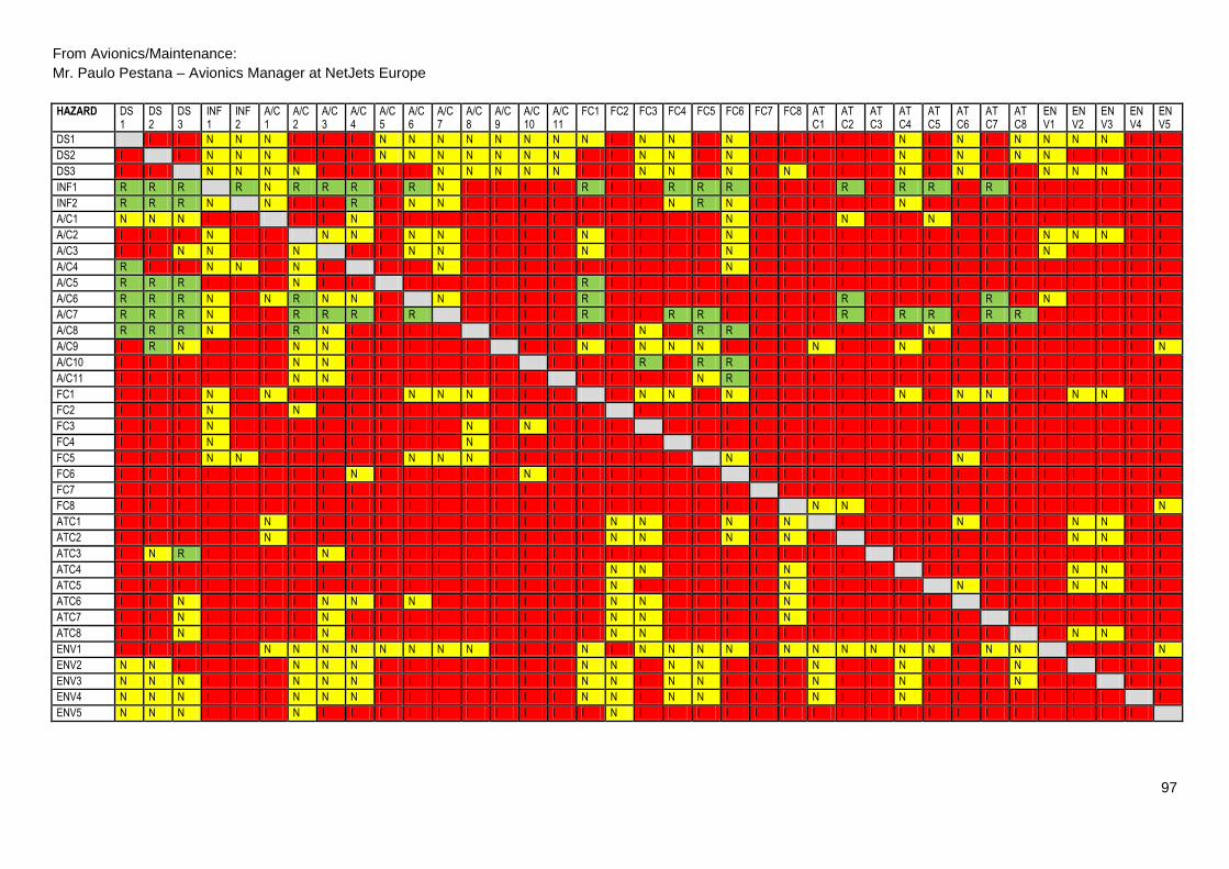
97
From Avionics/Maintenance:
Mr. Paulo Pestana – Avionics Manager at NetJets Europe
HAZARD DS1
DS2
DS3
INF1
INF2
A/C1
A/C2
A/C3
A/C4
A/C5
A/C6
A/C7
A/C8
A/C9
A/C10
A/C11
FC1 FC2 FC3 FC4 FC5 FC6 FC7 FC8 ATC1
ATC2
ATC3
ATC4
ATC5
ATC6
ATC7
ATC8
ENV1
ENV2
ENV3
ENV4
ENV5
DS1 I I N N N I I I N N N N N N N N I N N I N I I I I I N I N I N N N N I I
DS2 I I N N N I I I N N N N N N N I I N N I N I I I I I N I N I N N I I I I
DS3 I I N N N N I I I I N N N N N I I N N I N I N I I I N I N I I N N N I I
INF1 R R R R N R R R I R N I I I I R I I R R R I I I R I R R I R I I I I I I
INF2 R R R N N I I R I N N I I I I I I I N R N I I I I I N I I I I I I I I I
A/C1 N N N I I I I N I I I I I I I I I I I I N I I I N I I N I I I I I I I I
A/C2 I I I N I I N N I N N I I I I N I I I I N I I I I I I I I I I N N N I I
A/C3 I I N N I I N I I N N I I I I N I I I I N I I I I I I I I I I N I I I I
A/C4 R I I N N I N I I I N I I I I I I I I I N I I I I I I I I I I I I I I I
A/C5 R R R I I I N I I I I I I I I R I I I I I I I I I I I I I I I I I I I I
A/C6 R R R N I N R N N I N I I I I R I I I I I I I I R I I I I R I N I I I I
A/C7 R R R N I I R R R I R I I I I R I I R R I I I I R I R R I R R I I I I I
A/C8 R R R N I I R N I I I I I I I I I N I R R I I I I I I N I I I I I I I I
A/C9 I R N I I I N N I I I I I I I N I N N N I I I N I I N I I I I I I I I N
A/C10 I I I I I I N N I I I I I I I I I R I R R I I I I I I I I I I I I I I I
A/C11 I I I I I I N N I I I I I I I I I I I N R I I I I I I I I I I I I I I I
FC1 I I I N I N I I I I N N N I I I I N N I N I I I I I N I N N I I N N I I
FC2 I I I N I I N I I I I I I I I I I I I I I I I I I I I I I I I I I I I I
FC3 I I I N I I I I I I I I N I N I I I I I I I I I I I I I I I I I I I I I
FC4 I I I N I I I I I I I I N I I I I I I I I I I I I I I I I I I I I I I I
FC5 I I I N N I I I I I N N N I I I I I I I N I I I I I I I N I I I I I I I
FC6 I I I I I I I I N I I I I I N I I I I I I I I I I I I I I I I I I I I I
FC7 I I I I I I I I I I I I I I I I I I I I I I I I I I I I I I I I I I I I
FC8 I I I I I I I I I I I I I I I I I I I I I I I N N I I I I I I I I I I N
ATC1 I I I I I N I I I I I I I I I I I N N I I N I N I I I I N I I I N N I I
ATC2 I I I I I N I I I I I I I I I I I N N I I N I N I I I I I I I I N N I I
ATC3 I N R I I I I N I I I I I I I I I I I I I I I I I I I I I I I I I I I I
ATC4 I I I I I I I I I I I I I I I I I N N I I I I N I I I I I I I I N N I I
ATC5 I I I I I I I I I I I I I I I I I N I I I I I N I I I I N I I I N N I I
ATC6 I I N I I I I N N I N I I I I I I N N I I I I N I I I I I I I I I I I I
ATC7 I I N I I I I N I I I I I I I I I N N I I I I N I I I I I I I I I I I I
ATC8 I I N I I I I N I I I I I I I I I N N I I I I I I I I I I I I I N N I I
ENV1 I I I I I N N N N N N N N I I I N I N N N N I N N N N N N I N N I I I N
ENV2 N N I I I I N N N I I I I I I I N N I N N I I I N I I N I I I N I I I I
ENV3 N N N I I I N N N I I I I I I I N N I N N I I I N I I N I I I N I I I I
ENV4 N N N I I I N N N I I I I I I I N N I N N I I I N I I N I I I I I I I I
ENV5 N N N I I I N I I I I I I I I I I N I I I I I I I I I I I I I I I I I I

98
From Flight Crew 1:
Mr. Marco Pereira – Captain and Flight Ops Technical Pilot at NetJets Europe
HAZARD DS1
DS2
DS3
INF1
INF2
A/C1
A/C2
A/C3
A/C4
A/C5
A/C6
A/C7
A/C8
A/C9
A/C10
A/C11
FC1 FC 2
FC3 FC4 FC5 FC6 FC7 FC8 ATC1
ATC2
ATC3
ATC4
ATC5
ATC6
ATC7
ATC8
ENV1
ENV2
ENV3
ENV4
ENV5
DS1 I I I I I N I I I I I I I I I I I I I I I I I I I I I I I I I I I I I N
DS2 I I I I I I I I I I I I I I I I I I I I I I I I I I I I I I I I I I I I
DS3 I I N N I I I N I I I I N N I I I I N I N I I N I I N N N N N N N N N N
INF1 N I N N I I I I I I I I I I I I I I I I I I I I I I I I I I I N I I I I
INF2 I I I I I I I I I I I I I I I I I I I I I I I I I I I I I I I I I I I I
A/C1 I I I I I I I I I I I I N I I I I I I I I I I I I I I I I I I I I I I I
A/C2 I I I I I I I I I I I I I I I I I I I I I I I I I I I I I I I I I I I I
A/C3 I I I I I I I I I I I I I I I I I I I I I I I I I I I I I I I I I I I I
A/C4 I I I I I I I I I I I I I I I I I I I I I I I I I I I I I I I I I I I I
A/C5 I I I I I I I I I I I I I I I I I I I I I I I I I I I I I I I I I I I I
A/C6 I I I I I I I I I I I I I I I I I I I I I I I I I I I I I I I I I I I I
A/C7 I I I I I I I I I I I I I I I I I I I I I I I I I I I I I I I I I I I I
A/C8 I I I I I I I I I I I I I I I I I I I I I I I I I I I I I I I I I I I I
A/C9 I I I I I I I I I I I I I I I I I I I I I I I I I I I I I I I I I I I I
A/C10 I I I I I I I I I I I I I I I I I I I I I I I I I I I I I I I I I I I I
A/C11 I I I I I I I I I I I I I I I I I I I I I I I I I I I I I I I I I I I I
FC1 I I I I I I I I I I I I I I I I I I I I I I I I I I I I I I I I I I I I
FC2 I I I I I I I I I I I I I I I I I I I I I I I I I I I I I I I I I I I I
FC3 I I I I I I I I I I I I I I I I I I I I I I I I I I I I I I I I I I I I
FC4 I I I I I I I I I I I I I I I I I I I I I I I I I I I I I I I I I I I I
FC5 I I I I I I I I I I I I I I I I I I I I I I I I I I I I I I I I I I I I
FC6 I I I I I I I I I I I I I I I I I I I I I I I I I I I I I I I I I I I I
FC7 I I I I I I I I I I I I I I I I I I I I I I I I I I I I I I I I I I I I
FC8 I I I I I I I I I I I I I I I I I I I I I I I I I I I I I I I I I I I I
ATC1 I I I I I I I I N I I I I I I I I I I I I I I I I I I I I I I I I I I I
ATC2 I I I I I I I I I I I I I I I I I I I I I I I I I I I I I I I I I I I I
ATC3 I I I I I I I I I I I I I I I I I I I I I I I I I I I I I I I I I I I I
ATC4 I I I I I I I I I I I I I I I I I I I I I I I I I I I I I I I I I I I I
ATC5 I I I I I I I I I I I I I I I I I I I I I I I I I I I I I I I I I I I I
ATC6 I I I I I I I I I I I I I I I I I I I I I I I I I I I I I I I I I I I I
ATC7 I I I I I I I I I I I I I I I I I I I I I I I I I I I I I I I I I I I I
ATC8 I I I I I I I I I I I I I I I I I I I I I I I I I I I I I I I I I I I I
ENV1 I I I I I I I I I I I I I I I I I I I I I I I I I I I I I I I I I I I I
ENV2 I I I I I I I I I I I I I I I I I I I I I I I I I I I I I I I I I I I I
ENV3 I I I I I I I I I I I I I I I I I I I I I I I I I I I I I I I I I I I I
ENV4 I I I I I I I I I I I I I I I I I I I I I I I I I I I I I I I I I I I I
ENV5 I I I I I I I I I I I I I I I I I I I I I I I I I I I I I I I I I I I I

99
From Flight Crew 2:
Mr. Erik Verheijden – Captain and Flight Ops Technical Pilot at NeJets Europe
HAZARD DS1 DS2 DS3 INF1
INF2
A/C1
A/C2
A/C3
A/C4
A/C5
A/C6
A/C7
A/C8
A/C9
A/C10
A/C11
FC1 FC2 FC3 FC4 FC5 FC6 FC7 FC8 ATC1
ATC2
ATC3
ATC4
ATC5
ATC6
ATC7
ATC8
ENV1
ENV2
ENV3
ENV4
ENV5
DS1 R R N I N N N N N N N N N N N I N N I N N I I N I N N I I N N N I I N N
DS2 N N I N N N N N N N N N N N N I N N N N N I N N N N N N I N N N I I N N
DS3 N N N I N N N I N N N N N N N N I N N N N N N N N N N N N N N N I I N N
INF1 N N N N N N N N I N N N N I I R I N N R N N N N I N N N N N N N I I N N
INF2 N N I I N N N N N N I N N I N N I N N N N N N N N N N N N N N N N N N N
A/C1 N N N N N N N N N N N N N N N N N N N N N N N N N N N N N N N N N N N I
A/C2 N N N N N N I N N N N N N N N I N N N I N I N N I N I N N N N N I I N N
A/C3 N N N N N N N N N N N N N N N I N N N N N N N N I N N N N N N N N N N N
A/C4 N N N N I N N N N N N N N N N N I N N N N N N N N N N N N N N N N N N N
A/C5 N N N N N N N N N I I I I I N N I I N N N I N N N N N N N N N N N N N N
A/C6 N N N N N N N N N N N N N N N I I N N N N N N N N N N N N N N N N N N N
A/C7 N N N N N N N N N N N I N N I N I N N N N N N N N N N N N N N N N N N N
A/C8 I N N N N N N N N I I I I I I N I I N N N N N N N N N N N N N N N N N I
A/C9 N N N N N N N N N I N N I I N N I N N N N N N N N N N N N N N N I I N N
A/C10 N N N I I N N N N I I I I I N N I I N N I N N N N N N N N N N I N N I I
A/C11 N N N N N N N N N I I I I I I N N N N N N N N N N N N N N N N N N N N N
FC1 N I I N N N I N N N I I N N N N N N N N N N N N N N N I N N I N N N N N
FC2 N N N I I N N N N I I I I I I I N N N N N N N N N N N N N N N N N N N N
FC3 N N N N N N I I N N N N I N I N N N N N I N N N N N I N N N N N N N N N
FC4 N N N N I I N N I I I I I I I N N N N N I N N N N N N N N N N N N N N N
FC5 I I I I I N I I I N N N N N N N I N N N N I N N N N N N N N N N N N N N
FC6 N N N N I N N N N N N N N N I N N N N N N I N N N N N N N N N N N N N N
FC7 N N N N N N N I N N N N N N N N I N N N I N I N N N I N N N I N N N N N
FC8 I N N N N N N N N I N N I I I N N N N N N N N N N N N N N N N N N N N N
ATC1 I N N N N N N N N I I I I N N N N N N I N I N N N N I N N N N N N N N N
ATC2 I I I N N N N N N N N N N N N N I N N N N N N N N N N N N N N N N N N N
ATC3 N N N I I N I I N N N N I N N N I I I N I N N N N N I N N N N N N N N I
ATC4 N N N N N N N I I N N N N N N N N N N N N N I N N N N I N N N N N N N I
ATC5 N N N N N N N N N N N N N N N N I N N N N N N N I N N N N N N N N N N I
ATC6 I I N N N N N N N N N N N N N N N N N N N N N N N N N N N N N N I I N N
ATC7 N N N N N N N N I I N N N N N N I N I I N I I N N N N N I N N N N N N I
ATC8 N N N N N N N N N I I I N N I N I N I I N I N N I N N I N N I N N N N N
ENV1 N N N N N N N N N N N N N N N N N N I N N N I I N N N N N N N N N N N N
ENV2 N N N N N N N N N N N N N N N N N N N N N I N N N N N N N N N N N I N N
ENV3 N N N N N N N N N N N N N N N N N N N N N I N N N N N N N N N N N N N N
ENV4 N N N N N N N N N N N N N N N N N N N N N I N N N N N N N N N N N N N N
ENV5 N N N N N I N N N N N N N I N N N N N N N N N N N N N N N N N N N N N N

100
APPENDIX V – STATISTICAL ANALYSIS FOR INCREASED SEVERITY
HAZARD DS1 DS2 DS3 INF
1 INF2
A/C1
A/C2
A/C3
A/C4
A/C5
A/C6
A/C7
A/C8
A/C9
A/C10
A/C11
FC1 FC2 FC3 FC4 FC5 FC6 FC7 FC8 ATC1
ATC2
ATC3
ATC4
ATC5
ATC6
ATC7
ATC8
ENV1
ENV2
ENV3
ENV4
ENV5
DS1 0 0,75 0,75 0,5 0,75 0,25 0,5 0,75 0,75 0,25 0,25 0,5 0,5 0,25 0,5 0,25 0,75 0,5 0,5 0,75 0,75 0,5 0,75 0,75 0,75 1 0,5 0,5 0,75 0,75 0,75 0,5 0,25 0,75 0,75 0,75 0,25
DS2 0,75 0 0,75 0,75 0,5 0,25 0,75 0,75 0,75 0,25 0,25 0,5 0,5 0,25 0,5 0,25 1 0,5 0,5 0,5 0,75 0,25 0,75 0,5 0,75 0,75 0,5 0,25 0,75 0,75 0,75 0,5 0,25 1 1 0,75 0,5
DS3 0,75 0,75 0 0,25 0,5 0,5 0,5 0,75 0,75 0,5 0,75 0,5 0,5 0 0,25 0,25 0,75 0,75 0,5 0,25 0,75 0 0,75 0,25 0,5 0,75 0,75 0 0,25 0 0,25 0,5 0 0,25 0,25 0,25 0,25
INF1 0 0,25 0 0 0,25 0,5 0,5 0,5 0,5 0,75 0,25 0,5 0,75 0,5 1 0,75 0,5 0,75 0,75 0,5 0,5 0,25 0,5 0,5 0,75 0,5 0,75 0,5 0,25 0,5 0,25 0,75 0,25 0,75 0,75 0,5 0,5
INF2 0,5 0,5 0,75 0,75 0 0,5 0,75 0,75 0,5 0,5 0,25 0,75 0,75 0,5 1 0,5 0,75 0,75 0,75 0,5 0,5 0,25 0,5 0,5 0,75 0,75 0,75 0,25 0,5 0,5 0,5 0,75 0,5 0,75 0,75 0,75 0,5
A/C1 0,25 0,25 0,5 0,75 0,75 0 0,75 0,75 0,5 0,5 0,5 0,75 0,75 0,25 0,75 0,5 0,5 0,5 0,75 0,75 0,5 0,25 0,5 0,5 0,5 0,25 0,5 0,75 0,25 0,5 0,5 0,5 0,5 0,75 0,5 0,75 0,75
A/C2 0,75 0,5 0,75 0,5 0,75 0,75 0 0,5 0,25 0,5 0,25 0,5 0,75 0,5 0,75 0,5 0,5 0,5 0,75 0,75 0,75 0,25 0,75 0,5 0,5 1 0,5 0,75 0,5 0,5 0,5 0,5 0,25 0,5 0,5 0,5 0,5
A/C3 0,5 0,5 0,5 0,25 0,75 0,75 0,25 0 0,5 0,5 0,25 0,5 0,75 0,5 0,75 0,5 0,5 0,5 0,5 0,5 0,75 0,25 0,5 0,5 0,75 0,75 0,75 0,75 0,5 0,5 0,5 0,5 0,25 0,5 0,5 0,5 0,5
A/C4 0,25 0,5 0,75 0,5 0,75 0,75 0,5 0,5 0 0,5 0,5 0,5 0,75 0,5 0,75 0,5 0,75 0,75 0,75 0,75 0,75 0,25 0,5 0,5 0,75 0,5 0,75 0,75 0,5 0,75 0,5 0,75 0,5 0,75 0,75 0,75 0,5
A/C5 0,25 0,25 0,25 0,75 0,75 0,5 0,25 0,5 0,5 0 0,75 1 1 0,75 1 0,5 0,25 1 1 0,5 0,5 0,5 0,75 0,75 0,5 0,75 0,5 0,5 0,5 0,5 0,5 0,5 0,5 0,5 0,5 0,5 0,5
A/C6 0,25 0,25 0,25 0,5 0,5 0,25 0,25 0,25 0,25 0,5 0 0,5 0,75 0,5 0,75 0,5 0,5 0,75 0,5 0,75 0,75 0,5 0,5 0,5 0,75 0,25 0,75 0,5 0,5 0,5 0,25 0,5 0,25 0,5 0,5 0,5 0,5
A/C7 0,5 0,5 0,5 0,25 0,75 0,5 0,25 0,25 0,25 0,5 0,25 0 1 0,5 0,75 0,75 0,25 0,75 0,75 0,5 0,5 0,5 0,5 0,5 0,75 0,25 0,75 0,5 0,5 0,75 0,25 0,5 0,5 0,75 0,75 0,75 0,5
A/C8 0,75 0,5 0,5 0,5 0,75 0,75 0,5 0,5 0,75 1 0,75 1 0 0,75 0,75 0,75 0,75 0,75 0,5 0,5 0,25 0,5 0,5 0,75 0,75 0,75 0,75 0,75 0,5 0,75 0,75 0,5 0,75 0,75 0,75 0,75 0,75
A/C9 0,5 0,25 0,25 0,5 0,5 0,5 0,25 0,25 0,5 0,75 0,5 0,5 0,75 0 0,75 0,75 0,25 0,75 0,25 0,25 0,25 0,5 0,5 0,75 0,25 0,5 0,5 0,25 0,5 0,5 0,5 0,5 0,5 0,75 0,75 0,5 0,25
A/C10 0,75 0,75 0,75 1 1 0,75 0,25 0,25 0,5 1 0,75 1 0,75 0,75 0 0,5 0,5 0,75 0,5 0,75 0,5 0,5 0,5 0,5 0,5 0,75 0,75 0,5 0,5 0,75 0,75 0,5 1 0,75 0,75 1 0,75
A/C11 0,5 0,5 0,5 0,5 0,5 0,5 0,25 0,25 0,5 0,75 0,75 0,75 0,75 1 0,75 0 0,5 0,75 0,5 0,75 0,25 0,25 0,75 0,75 0,5 0,5 0,75 0,5 0,5 0,75 0,5 0,5 0,5 0,5 0,75 0,5 0,5
FC1 0,75 1 1 0,25 0,75 0,25 0,75 0,5 0,75 0,5 0,5 0,75 0,25 0,5 0,75 0,5 0 0,5 0,5 0,25 0,75 0,25 0,75 0,5 0,5 0,5 0,75 0,25 0,75 0,25 0,25 0,75 0,5 0,25 0,25 0,5 0,5
FC2 0,5 0,5 0,5 0,75 1 0,5 0,25 0,5 0,5 1 1 1 1 1 1 1 0,5 0 0,5 0,5 0,5 0,5 0,5 0,75 0,5 0,5 0,75 0,5 0,5 0,5 0,5 0,5 0,5 0,5 0,5 0,5 0,5
FC3 0,75 0,75 0,75 0,5 0,75 0,5 0,75 0,75 0,5 0,5 0,5 0,75 0,75 0,5 0,75 0,5 0,5 0,5 0 0,5 0,75 0,75 0,5 0,75 0,5 0,5 0,75 1 0,5 0,5 0,5 0,5 0,75 0,5 0,5 0,5 0,5
FC4 0,5 0,5 0,5 0,25 0,75 0,75 0,5 0,5 0,75 0,75 0,75 0,75 0,5 1 1 0,75 0,5 0,75 0,5 0 0,5 0,75 0,5 0,75 0,5 0,5 0,75 0,75 0,75 0,5 0,75 0,5 0,5 0,5 0,5 0,5 0,5
FC5 1 1 1 0,75 0,75 0,5 1 0,75 1 0,5 0,25 0,5 0,5 0,5 0,75 0,5 1 0,5 0,75 0,75 0 0,5 1 0,5 0,75 0,5 0,75 0,75 0,75 0,25 0,75 0,75 0,5 0,75 0,75 0,75 0,5
FC6 0,5 0,75 0,5 0,75 1 0,5 0,5 0,5 0,25 0,5 0,5 0,75 0,5 0,75 0,5 0,5 0,75 0,75 0,5 0,5 0,5 0 0,75 0,5 0,75 0,75 0,75 0,5 0,5 0,5 0,75 0,75 0,5 0,5 0,5 0,5 0,5
FC7 0,5 0,75 0,5 0,75 0,5 0,5 0,5 0,75 0,75 0,5 0,75 0,75 0,75 0,75 0,75 0,5 1 0,75 0,5 0,5 0,75 0,75 0 1 0,75 0,75 0,75 1 0,75 0,75 0,5 1 0,5 0,75 0,75 0,5 0,5
FC8 0,75 0,5 0,5 0,5 0,5 0,5 0,5 0,5 0,5 0,75 0,5 0,75 1 1 1 0,75 0,5 0,75 0,75 0,75 0,5 0,5 0,75 0 0,25 0,25 0,75 0,75 0,75 0,75 0,5 0,5 0,5 0,75 0,75 0,75 0,25
ATC1 0,75 0,5 0,5 0,5 0,5 0,25 0,5 0,5 0,25 0,75 0,75 0,75 0,75 0,5 0,75 0,5 0,5 0,25 0,5 0,75 0,75 0,5 0,75 0,25 0 0,75 0,75 1 0,75 0,5 0,75 0,75 0,5 0,5 0,5 0,75 0,5
ATC2 0,75 0,75 0,75 0,5 0,5 0,25 0,5 0,5 0,5 0,75 0,5 0,75 0,75 0,5 0,75 0,5 0,75 0,25 0,25 0,5 0,75 0,5 0,75 0,25 0,75 0 0,75 0,75 0,75 0,75 0,75 0,75 0,5 0,5 0,5 0,75 0,5
ATC3 0,5 0,25 0,25 1 1 0,75 1 0,75 0,75 0,5 0,5 0,75 1 0,5 0,75 0,5 0,75 1 0,75 0,5 0,75 0,5 0,75 0,5 0,75 0,75 0 0,75 0,5 0,5 0,5 0,75 0,5 0,5 0,5 0,5 1
ATC4 0,5 0,5 0,5 0,75 0,75 0,75 0,75 1 1 0,5 0,5 0,75 0,75 0,5 0,75 0,5 0,5 0,25 0,5 0,75 0,75 0,75 1 0,5 0,75 0,75 0,75 0 0,75 0,5 0,5 0,5 0,5 0,25 0,25 0,5 0,75
ATC5 0,5 0,5 0,75 0,75 0,75 0,5 0,75 0,75 0,75 0,5 0,5 0,75 0,75 0,5 0,75 0,5 0,75 0,5 0,75 0,75 0,5 0,75 0,75 0,25 1 0,75 0,75 0,5 0 0,5 0,75 0,75 0,5 0,5 0,25 0,75 0,75
ATC6 0,75 0,75 0,5 0,5 0,5 0,5 0,5 0,25 0,5 0,5 0,5 0,75 0,75 0,5 0,75 0,5 0,75 0,5 0,5 0,75 0,75 0,75 0,75 0,25 0,75 0,75 0,75 0,75 0,75 0 0,75 0,75 0,5 0,75 0,75 0,5 0,5
ATC7 0,75 0,75 0,5 0,75 0,5 0,5 0,5 0,25 0,75 0,75 0,75 0,75 0,75 0,5 0,75 0,5 0,75 0,5 0,75 1 0,75 1 1 0,25 0,75 0,75 0,75 0,75 1 0,75 0 0,75 0,5 0,5 0,5 0,5 0,75
ATC8 0,5 0,5 0,25 0,5 0,5 0,75 0,75 0,5 0,75 0,75 0,75 1 0,75 0,5 1 0,5 1 0,5 0,75 0,75 0,5 0,75 0,75 0,5 1 0,75 0,75 1 0,75 0,75 1 0 0,5 0,5 0,5 0,75 0,5
ENV1 0,5 0,5 0,5 0,5 0,5 0,25 0,25 0,25 0,25 0,25 0,25 0,25 0,25 0,75 0,5 0,75 0,25 0,75 0,5 0,25 0,25 0,25 0,75 0,75 0,25 0,25 0,25 0,25 0,25 0,5 0,25 0,25 0 0,75 0,75 0,75 0,25
ENV2 0,5 0,5 0,5 0,5 0,5 0,5 0,25 0,25 0,25 0,5 0,75 0,75 0,75 0,5 0,75 0,5 0,25 0,5 0,75 0,25 0,5 0,75 0,75 0,75 0,5 0,75 0,5 0,25 0,5 0,5 0,5 0,25 0,75 0 1 0,75 0,5
ENV3 0,25 0,25 0,25 0,5 0,5 0,5 0,25 0,25 0,25 0,5 0,75 0,75 0,75 0,5 0,75 0,5 0,25 0,5 0,75 0,25 0,5 0,75 0,75 0,75 0,5 0,75 0,5 0,25 0,5 0,5 0,5 0,25 0,75 0,75 0 0,75 0,5
ENV4 0,25 0,25 0,25 0,5 0,5 0,5 0,25 0,25 0,25 0,5 0,75 0,75 0,75 0,75 0,75 0,75 0,25 0,25 0,5 0,25 0,25 0,75 0,5 0,5 0,25 0,5 0,5 0,25 0,5 0,75 0,75 0,75 0,75 0,75 0,75 0 0,5
ENV5 0,25 0,25 0,25 0,5 0,5 0,75 0,25 0,5 0,5 0,5 0,5 0,5 0,5 0,75 0,5 0,5 0,5 0,25 0,5 0,5 0,5 0,5 0,5 0,5 0,5 0,5 0,75 0,5 0,5 0,5 0,5 0,5 0,5 0,5 0,5 0,5 0

101
APPENDIX VI
RNP-AR MONITORING
1. DATE OF FLIGHT 2. LOCAL TIME 3. AIRCRAFT TYPE 4. AIRCRAFT REGISTRATION
D M Y DAY NIGHT
____ / ____ / ______ _____H_____
5. CREW 6. PILOT FLYING
7. AIRPORT ID
(ICAO CODE)
8. PROCEDURE FLOWN
PIC:_______________________________ PIC SIC
SIC: _______________________________
9. PROCEDURE RESULT: SATISFACTORY UNSATISFACTORY
10. IF UNSATISFACTORY - What Navigation System (CASS/FMS) message(s) were received:
Excessive Lateral Deviation: L R +/- ________
Excessive Vertical Deviation: A B +/- ________
EGPWS Alert: Y N
Autopilot System Disconnect: Y N
(Not pilot initiated)
Navigation Data Errors: HDG ________ DIST ________ WAYPT ________
Satellites Tracked:
FOM:________________________________________________________________________________________
Other :_______________________________________________________________________________________
11. CREW COMMENTS:
FILING INSTRUCTIONS:
SEND TO …..
BY FAX Nº:……, or
BY E-MAIL: ……
SIGNATURE PILOT LICENSE & Nº
REPORT NR. º
____________