Embed Size (px)
Citation preview

Flicker Noise Modeling in BSIM6
Compact Model
Harshit Agarwal, Yogesh S. Chauhan
Nanolab
Department of Electrical Engineering
Indian Institute of Technology Kanpur, India

Outline
• Introduction to BSIM6 Model
• Flicker Noise Modeling in BSIM6
• Flicker Noise Model for Halo Implanted
MOSFETs
2

BSIM6: Industry Standard Bulk Model
3Fig: BSIM6 core model
1- Calculate pinch-off potentialYp
2- Next, source and drain inversion charge density is calculated
3- Calculate drain current 4- Obtain Charges : gate, drain, source and body charge
• BSIM6 is the latest industry standard model of bulk MOSFET
• It inherits popular real device effects, like CLM, DIBL etc., from BSIM4.
BSIM6 Core Model

BSIM6 Validation – IDS-VGS
4
gm (linear)
gm (sat)
Both linear and sat region
Excellent accuracy

BSIM6 Validation – Gate Capacitance
5
PMOS NMOS

1. McWhorter’s – Fluctuation in carrier number due to trapping/de-trapping
2. Hooge’s – Fluctuation in mobility due to phonon scattering
Flicker Noise Model
Source of Flicker Noise – Traps in Gate Dielectric
Two parallel theories for flicker noise-
6K. Hung, et al., IEEE Trans. Electron Devices, vol. 37, no. 37, pp. 654-665, March 1990
𝛿𝜇 → 𝛿𝐼𝐷𝑆
𝛿𝑁 → 𝛿𝐼𝐷𝑆
Unified Models – Takes care of both number and
mobility fluctuation theories
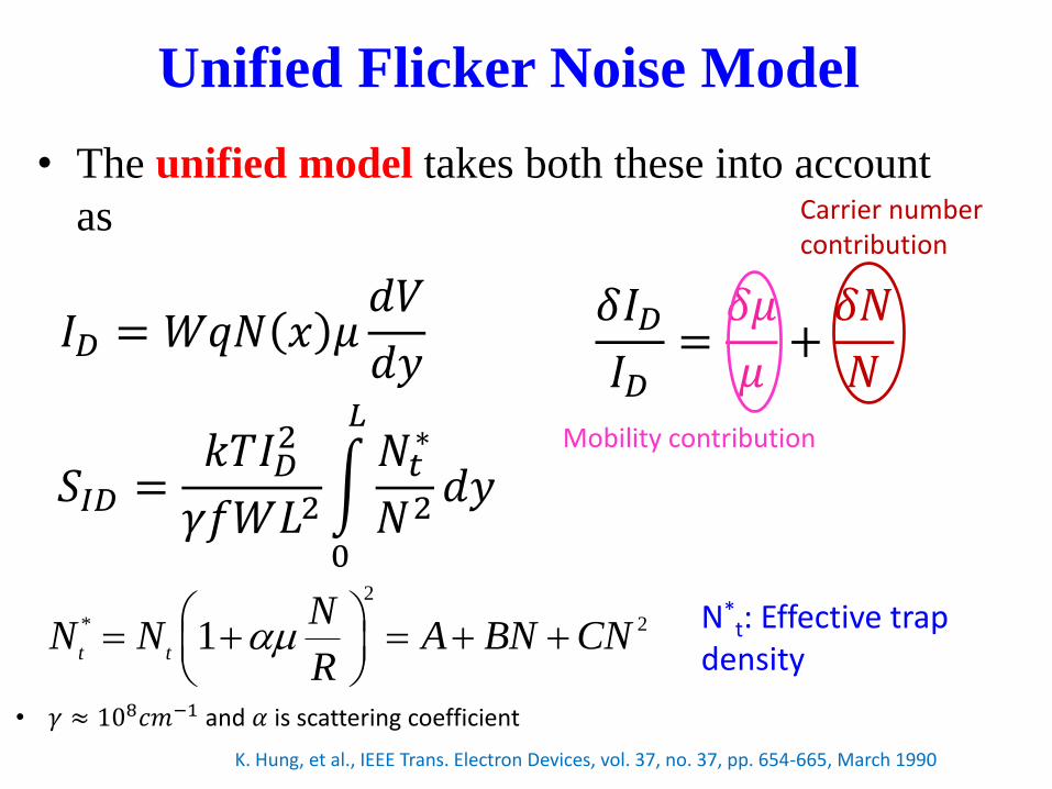
Unified Flicker Noise Model
• The unified model takes both these into account
as
K. Hung, et al., IEEE Trans. Electron Devices, vol. 37, no. 37, pp. 654-665, March 1990
• 𝛾 ≈ 108𝑐𝑚−1 and 𝛼 is scattering coefficient
𝛿𝐼𝐷𝐼𝐷=𝛿𝜇
𝜇+𝛿𝑁
𝑁
𝑆𝐼𝐷 =𝑘𝑇𝐼𝐷
2
𝛾𝑓𝑊𝐿2
0
𝐿𝑁𝑡∗
𝑁2𝑑𝑦
𝐼𝐷 = 𝑊𝑞𝑁 𝑥 𝜇𝑑𝑉
𝑑𝑦
Mobility contribution
Carrier number contribution
2
* 21t t
NN N A BN CN
R
N*t: Effective trap
density

Unified Flicker Noise Model
Unified flicker noise model
– Implemented in many commercial models
– More than a decade old, captures noise behavior over
different technologies and across devices and biases
– Takes care of both carrier number and mobility
fluctuation effects
How good is it to model noise in advance structures
involving halo implants ..
8

Flicker Noise in Presence of Halo
Implant
9
• Advanced CMOS structures require halo implants to control
short channel effects.
N. Paydavosi, et al., “Flicker Noise Analysis in Advance CMOS Technologies”, ESSDERC, 2013.
• Noise behavior is qualitatively and quantitatively different
from uniformly doped devices
• Unified flicker noise model in its original form cannot
capture noise behavior of halo implanted devices
Possible reasons
1. Higher trap density in the
halo region
2. Non-uniform threshold
voltage along the channel

Summary
10
• Currently BSIM6 has flicker noise model which is
based on unified model
• Flicker Noise behavior of halo implanted structure is
different from uniformly doped MOSFETs
• Halo MOSFETs depicts significant gate bias
dependency
• Popular unified model in raw form cannot model flicker
noise
• New analytical model proposed

Acknowledgement
• Model users
• EDA Vendors
• CMC Members
• Funding agencies
• SRC/GRC
• CMC
• DST, Govt. of
India
• IIT Kanpur
11

Joint Development & Collaboration
• Working closely with universities/companies on
model development and support
12

Thank You
13