Embed Size (px)
Citation preview
Flexure Analysis
CCAT‐TM‐121
David Woody, July 17, 2013
Version 2: Change bipod dimensions to match the stiffness of SGH 10 mm thick flex plates with 6DOF
constraints top and bottom. Add more case studies.
Introduction
The design and performance of the connection between the steel tipping platform and the CFRP truss
is a critical part of the design of the CCAT primary. The connections must be rigid in the axial and
circumferential direction and very compliant in the radial direction to avoid transferring stress
between the steel tipping structure and the CFRP truss during large uniform temperature changes.
The seismic loads are quite high whereas only a small radial or squeezing stress will significantly distort
the truss. The problem is accentuated by the 3 m dia clearance cylinder through the truss along the
elevation axis required to accommodate instruments with a 1 deg field of view. Uniform radial
squeezing of the base of an axially symmetric truss would produce mostly a focus change, but in an
asymmetric truss this squeezing produces astigmatism and higher order distortions. This document
shows the FEA results for several different designs for the connection between the steel tipping
platform and the bottom of the truss.
Basic design and modelling approach
The SGH CCAT‐v14 model uses 10 mm thick x 250 mm high x 300 mm solid blades with 6 degrees of
freedom, DOF, constraints at both ends. The deflection of this plate as a function of lateral force was
modelled in Inventor. A bipod model was also built and modelled in Inventor with the cross‐section
adjusted to match the bending stiffness of the SGH blades. The bipods are modelled as beams and
are connected to the nodes in the bottom layer 5 of the truss. Because the Algor truss model above
the bipods uses pure truss members, i.e. pinned at the ends of the struts, the Inventor model for the
bipod has angular releases at the top whereas the Inventor version of the blade model has a sliding
constraint to mimic the 6DOF attachment to the truss beams in the CCAT‐v14 truss. The worst case
deformation (maximum thermal, axial and circumferential loads applied together) and stress for the
two models are shown in figs. 1 & 2.
The radial compliance of the attachment flexures can be changed by adjusting the thickness of the
blade flexure, using hinges at the top and bottom of the plate or changing the blade geometry.
Thinning the blades improves the radial compliance but the stress in the blade and buckling failure
become a serious problem. The hinge option gives the weakest radial compliance and hence the best
thermal performance but with added complexity and maintenance requirements. The bending
stiffness of a blade scales at the square of its thickness while the maximum stress for in plane force
scales linearly with the thickness. Thus you can use multiple thinner blades in parallel to preserve the
maximum load carrying capability while decreasing the bending stiffness. Buckling is still an issue and
so a more complex blade design is required that is thinner at the ends and thicker in the middle. The
width of the blades can also be changed to make the flexures stronger in the tangential direction but
this doesn’t help much because of local distortions at the attachment to the truss nodes.
Another parameter that can be adjusted to improve the thermal performance is the cross‐section of
the CFRP struts in the bottom layer 5 of the truss. Making layer 5 stiffer decreases the strain from the
squeezing stress from the blades and decreases the deformation of the truss.
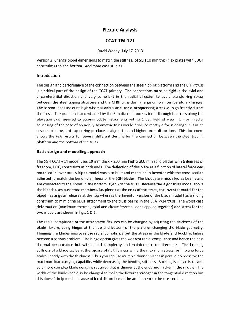
The Algor model constrains the bottom of the bipods in a fixed reference frame. The differential
expansion between where the bipods attach to the steel tipping platform with a CTE of 10 ppm/C and
the CFRP truss with 0.2 ppm/C was simulated by increasing the soak temperature change from 10 C
to 10C*(10ppm/C‐0.2ppm/C)/(0.2ppm/C)=500 C.
Fig. 1. Single blade flexure, 250 mm high x 300 mm wide x 10 mm thick. The loads are 750 N radial,
142 kN vertically and 81 kN circumferentially. The top displacement in X is 0.12 mm.
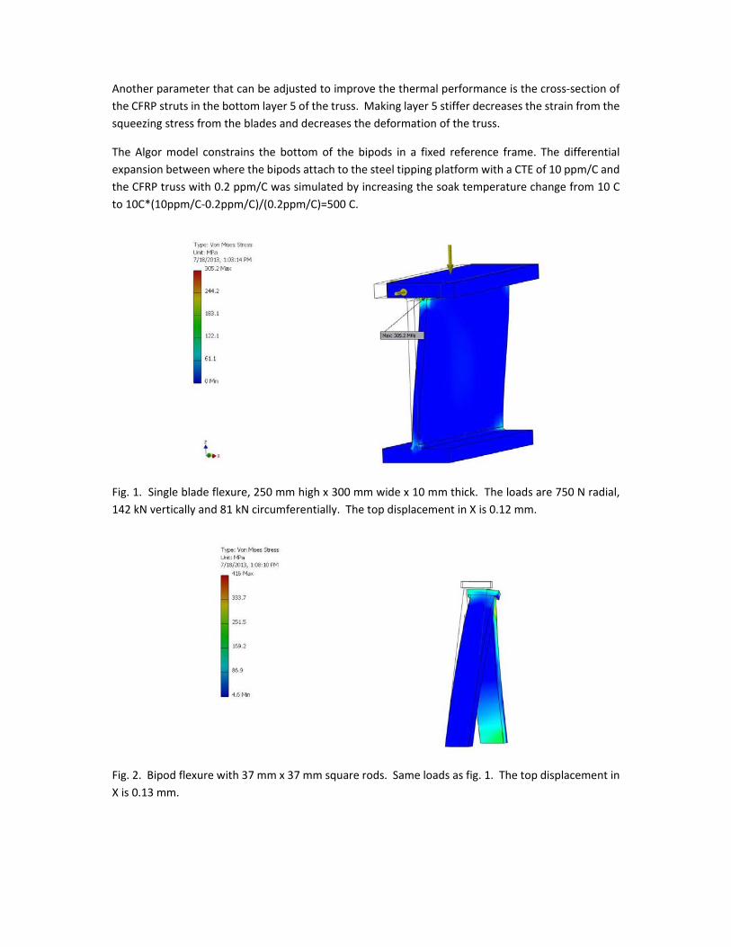
Fig. 2. Bipod flexure with 37 mm x 37 mm square rods. Same loads as fig. 1. The top displacement in
X is 0.13 mm.

Case studies
Several cases have been analyzed, starting from an approximation of the SGH model (CCAT‐v14) under
thermal load and then modification of the bipods and layer 5 struts in stages to arrive at viable designs
for the bottom truss layer and flexures.
Case1: SGH CCAT‐v14 model approximation using 37 mm square bipods. The layer 5 strut cross‐
section is the nominal 430 mm2.
The lowest modal frequency, f0, for this case is 11.1255 Hz.
The radial displacement in layer 5 outer node ring relative to steel platform varied from 0.499 to 0.514
mm. The nominal displacement without any connection between the truss and tipping platform
would have been 0.580 mm, e.g. the flexures compressed the bottom layer of the truss by ~0.07 mm.
The large 3 m diameter cylindrical cut out of the truss along the elevation axis for instruments causes
a 15 m asymmetry in this deformation. Fig. 3 shows that the compressive forces in the outer radial
struts vary from 210 to 1300 N. The largest forces are in the struts directly below the elevation axis.
The bottom layer nodes along the X‐axis are not connected to the upper part of the truss and hence
have to carry the full squeezing force from the blade flexures whereas at the other nodes most of the
squeezing force is carried by the struts that connect to next layer of the truss. This produces a
distortion throughout the truss and deforms the final actuator node positions.
Figs. 4‐7 show the deflection in the axial or Z‐direction. The deflections are mostly a uniform
expansion as expected but there is a small asymmetric deviation from thermal homology caused the
non‐uniform response of the truss to the squeezing forces from the flexures. A measure of this effect
is the 11 m peak‐to‐peak variation in the Z deflection around the rim.

Fig. 3. Case 1 axial forces in the layer 5 struts. The elevation axis is along the X‐direction and the
asymmetry in the forces is apparent.
Fig. 4. Case 1 Z deflections. Side view along the elevation axis.

Fig. 5. Case 1 Z deflections for the actuator nodes. Side view.
Fig. 6. Case 1 Z deflections for the actuator nodes. Top view.

Fig. 7. Case 1 Z deflections for the actuator nodes. Top view with an expanded scale to show the 11
m p‐p asymmetric distortions around the rim.
Case 2: Increase the cross‐section of the layer 5 struts from 430 mm2 to 3,200 mm2, the same as the
struts connecting layer 5 to layer 4. The bipods cross‐section is still 37 mm x 37 mm with 6DOF
constraints at their attachment to the steel tipping platform.
The radial displacement of the layer 5 outer node ring relative to steel platform varies from 0.560 to
0.563 mm. The asymmetry is reduced to 3 m. The forces in the layer 5 radial struts are more uniform,
varying from 680 to 1500 N with less force being carried by the struts connecting to layer 4.
The plots of the axial deflections look essentially the same as figs. 4‐7 but the p‐p deflections at the
rim are now only 2.6 m.
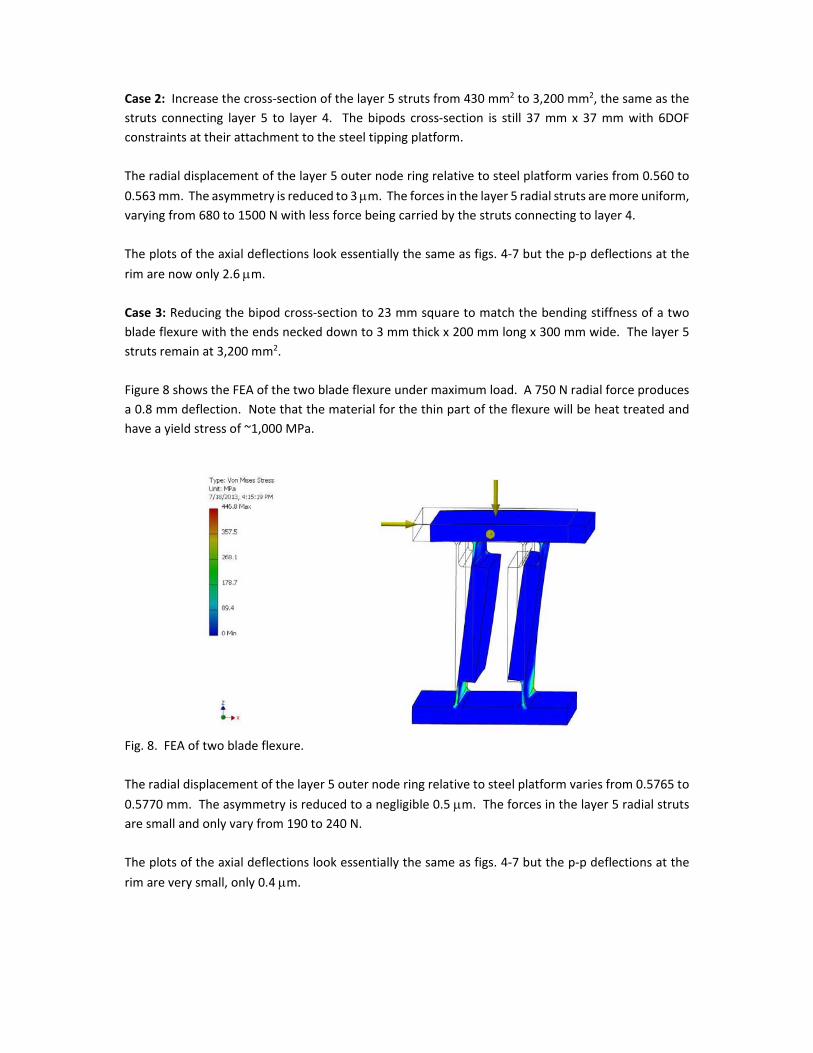
Case 3: Reducing the bipod cross‐section to 23 mm square to match the bending stiffness of a two
blade flexure with the ends necked down to 3 mm thick x 200 mm long x 300 mm wide. The layer 5
struts remain at 3,200 mm2.
Figure 8 shows the FEA of the two blade flexure under maximum load. A 750 N radial force produces
a 0.8 mm deflection. Note that the material for the thin part of the flexure will be heat treated and
have a yield stress of ~1,000 MPa.
Fig. 8. FEA of two blade flexure.
The radial displacement of the layer 5 outer node ring relative to steel platform varies from 0.5765 to
0.5770 mm. The asymmetry is reduced to a negligible 0.5 m. The forces in the layer 5 radial struts
are small and only vary from 190 to 240 N.
The plots of the axial deflections look essentially the same as figs. 4‐7 but the p‐p deflections at the
rim are very small, only 0.4 m.

Case 4: Reduce the layer 5 strut cross‐section from 3,200 mm2 to 860 mm2, twice its original value.
The bipod cross‐section is still 23 mm square to match the bending stiffness of the two blade flexure
shown in case 3. The equivalent single blade flexure that is appropriate for thermal analysis but not
sufficient for the maximum seismic load is 5 mm thick.
f0 for this case is 11.1618 Hz.
The layer 5 outer node ring radial displacement relative to steel platform varied from 0.569 to 0.572
mm. The asymmetry is 3 m. The forces in the layer 5 radial struts vary from 150 to 260 N. The plots
of the axial deflections look essentially the same as figs. 4‐7 and the p‐p deflections at the rim are an
acceptable 1.4 m.
Case 5: Mimic the SGH CCAT‐v14 model with 10 mm thick hinge plates with angular release along the
tangential direction at the top and bottom. The bipods have a 37 mm square cross‐section with
angular releases at the bottom and layer 5 struts have the original 430 mm2 cross‐section.
f0 for this case is 11.1212 Hz, 0.04 Hz lower than case 4.
The layer 5 outer node ring radial displacement relative to steel platform is a very uniform 0.5796 mm
with no asymmetry. The forces in the layer 5 radial struts are less the 10‐6 N, i.e. zero. The deflections
are simply uniform expansion and there is no detectable asymmetry in the rim deflections
Conclusion
Case 5 shows that hinge plates work exactly as expected and the truss deforms homologously with
the parabolic surface deforming to a parabolic surface with a slightly different focal length for a
uniform temperature change. It reality this will be limited by the uniformity of the temperature and
CTE of the truss. This requires good hinges using high quality preloaded rolling element bearings.
Case 4 using the double blade flexures shows acceptably small thermal soak distortions without having
to resort to hinge plates while still using modest size struts in layer 5. The ease of installation and no
required maintenance, just annual inspection, favours this solution. The trade space between layer 5
strut size and design of the double flex plate can be further optimized using detailed FEA of the
components and the full telescope structure to make sure the solution is robust and cost effective.
The lowest modal frequency of the primary for all of these cases are within a few 10s of mHz of being
the same and it is expected these changes will have no significant effect on the seismic load response
or on the telescope drive performance.