Embed Size (px)
Citation preview
Specimen Failure modea Mmax (Nm) TEN F/10 (mJ) c / (mJ)c
N1 A 9.1 89 31.7 (78.8) 152 (56.4) N2 A 11.9 69
N3 A 46.8 237 N4 A 58.8 215 G1b B 89.6 63117
65.7 (10.5) 8840 (10.9) G2 C 60.0 9652 G3 C 63.8 9089 G4 C 73.4 7778 C1 D 47.6 62
28.1 (47.3) 551 (75.5) C2 D 22.9 1079 C3 D 18.1 552 C4 E 23.6 512 S1 E 67.1 1914
57.9 (15.7) 2324 (56.3) S2 E 52.7 4199 S3 E 47.9 1154 S4 E 64.0 2028 P1 E 51.6 393
49.3 (5.0) 1093 (67.9) P2 C 49.6 1015 P3 D 46.7 1871 B1 D 30.8 2225
29.6 (14.7) 1484 (54.2) B2 D 33.3 1599 B3 D 24.8 629
a According with Figure 3. b Discarded data in the calculation of the average values. c Coefficient of variation in brackets (%).
SummaryThe negligible tensile strength of rammed earth and its lack of strain energy dissipation along tensile breaking process might compromise its application in many structural elements. Our research proposes using textile grids as a reinforcement system to enhance the tensile properties of rammed earth. An adapted methodology to assess the effect of embedding fibre grids, which is based on standards for fibrereinforced concrete elements is used. The ultimate bending moment and the flexural toughness have been determined for 22 compressed earth specimens using different types of grids and materials to reinforce them. The optimum solution is a flexible fibre grid with large spacing between fibre tows that ensures the connection to the earthen matrix.
IntroductionA few researches aimed to increase the tensile strength and the dissipated energy after the rammed earth cracks in tension have been found. These might be divided in two groups: the proposals aimed to externally strengthen earthen structures and those aimed to provide a reinforcing system placed inside the earthen material when casting the structure. Blondet et al. [1] worked in both alternatives, Liu et al. [2] proposed an external strengthening system and Tarque et al. [3] have even proposed a numerical model to simulate externally strengthened adobe walls.In parallel, using high performance fibre grids embedded into a inorganic matrixes to externally strengthen structures has been studied considering different points of view: experimental (see [4,5]), analytical (see [6]) or even with numerical simulations (see [7,8]).Gathering both knowledge resources, a
comprehensive experimental campaign focusedon analysing the structural response of fibre grid reinforced rammed earth specimens is presented. Different types of fibre grids are considered. The tests are focused on analysing the flexural toughness, so the Japanese Standard JSCE-SF4 [9] is taken into account as a reference as previously done in other experimental studies (see [10]).
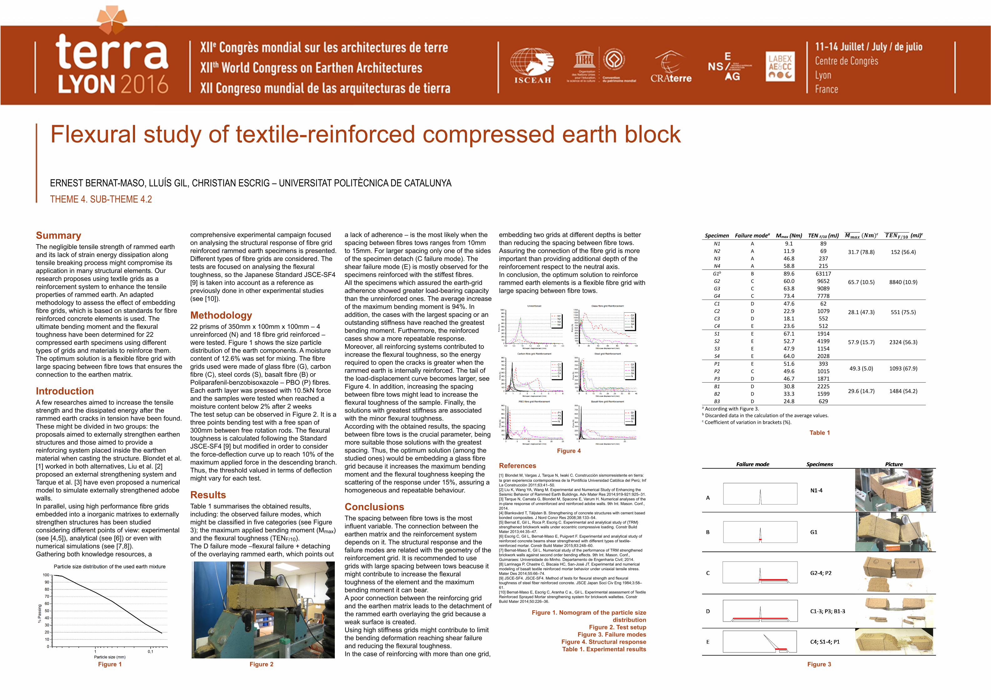
Methodology22 prisms of 350mm x 100mm x 100mm – 4 unreinforced (N) and 18 fibre grid reinforced –were tested. Figure 1 shows the size particle distribution of the earth components. A moisture content of 12.6% was set for mixing. The fibregrids used were made of glass fibre (G), carbon fibre (C), steel cords (S), basalt fibre (B) or Poliparafenil-benzobisoxazole – PBO (P) fibres. Each earth layer was pressed with 10.5kN force and the samples were tested when reached a moisture content below 2% after 2 weeksThe test setup can be observed in Figure 2. It is a three points bending test with a free span of 300mm between free rotation rods. The flexural toughness is calculated following the Standard JSCE-SF4 [9] but modified in order to consider the force-deflection curve up to reach 10% of the maximum applied force in the descending branch. Thus, the threshold valued in terms of deflection might vary for each test.
ResultsTable 1 summarises the obtained results, including: the observed failure modes, which might be classified in five categories (see Figure 3); the maximum applied bending moment (Mmax) and the flexural toughness (TENF/10).The D failure mode –flexural failure + detaching of the overlaying rammed earth, which points out
a lack of adherence – is the most likely when the spacing between fibres tows ranges from 10mmto 15mm. For larger spacing only one of the sides of the specimen detach (C failure mode). The shear failure mode (E) is mostly observed for the specimens reinforced with the stiffest fibres. All the specimens which assured the earth-grid adherence showed greater load-bearing capacity than the unreinforced ones. The average increase of the maximum bending moment is 94%. In addition, the cases with the largest spacing or an outstanding stiffness have reached the greatest bending moment. Furthermore, the reinforced cases show a more repeatable response. Moreover, all reinforcing systems contributed to increase the flexural toughness, so the energy required to open the cracks is greater when the rammed earth is internally reinforced. The tail of the load-displacement curve becomes larger, see Figure 4. In addition, increasing the spacing between fibre tows might lead to increase the flexural toughness of the sample. Finally, the solutions with greatest stiffness are associated with the minor flexural toughness.According with the obtained results, the spacing between fibre tows is the crucial parameter, being more suitable those solutions with the greatest spacing. Thus, the optimum solution (among the studied ones) would be embedding a glass fibregrid because it increases the maximum bending moment and the flexural toughness keeping the scattering of the response under 15%, assuring a homogeneous and repeatable behaviour.
ConclusionsThe spacing between fibre tows is the most influent variable. The connection between the earthen matrix and the reinforcement system depends on it. The structural response and the failure modes are related with the geometry of thereinforcement grid. It is recommended to use grids with large spacing between tows beacuse it might contribute to increase the flexural toughness of the element and the maximum bending moment it can bear.A poor connection between the reinforcing grid and the earthen matrix leads to the detachment of the rammed earth overlaying the grid because a weak surface is created. Using high stiffness grids might contribute to limit the bending deformation reaching shear failure and reducing the flexural toughness.In the case of reinforcing with more than one grid,
embedding two grids at different depths is better than reducing the spacing between fibre tows. Assuring the connection of the fibre grid is more important than providing additional depth of the reinforcement respect to the neutral axis.In conclusion, the optimum solution to reinforce rammed earth elements is a flexible fibre grid with large spacing between fibre tows.
References[1] Blondet M, Vargas J, Tarque N, Iwaki C. Construcción sismorresistente en tierra: la gran experiencia contemporánea de la Pontificia Universidad Católica del Perú; InfLa Construcción 2011;63:41–50.[2] Liu K, Wang YA, Wang M. Experimental and Numerical Study of Enhancing the Seismic Behavior of Rammed Earth Buildings. Adv Mater Res 2014;919-921:925–31.[3] Tarque N, Camata G, Blondet M, Spacone E, Varum H. Numerical analyses of the in-plane response of unreinforced and reinforced adobe walls. 9th Int. Mason. Conf., 2014.[4] Blanksvärd T, Täljsten B. Strengthening of concrete structures with cement based bonded composites. J Nord Concr Res 2008;38:133–54.[5] Bernat E, Gil L, Roca P, Escrig C. Experimental and analytical study of {TRM} strengthened brickwork walls under eccentric compressive loading. Constr Build Mater 2013;44:35–47.[6] Escrig C, Gil L, Bernat-Maso E, Puigvert F. Experimental and analytical study of reinforced concrete beams shear strengthened with different types of textile-reinforced mortar. Constr Build Mater 2015;83:248–60.[7] Bernat-Maso E, Gil L. Numerical study of the performance of TRM strengthened brickwork walls against second order bending effects. 9th Int. Mason. Conf., Guimaraes: Universidade do Minho. Departamento de Engenharia Civil; 2014.[8] Larrinaga P, Chastre C, Biscaia HC, San-José JT. Experimental and numerical modeling of basalt textile reinforced mortar behavior under uniaxial tensile stress. Mater Des 2014;55:66–74.[9] JSCE-SF4. JSCE-SF4. Method of tests for flexural strength and flexural toughness of steel fiber reinforced concrete. JSCE Japan Soci Civ Eng 1984;3:58–61.[10] Bernat-Maso E, Escrig C, Aranha C a., Gil L. Experimental assessment of Textile Reinforced Sprayed Mortar strengthening system for brickwork wallettes. ConstrBuild Mater 2014;50:226–36.
Figure 1. Nomogram of the particle size distribution
Figure 2. Test setupFigure 3. Failure modes
Figure 4. Structural responseTable 1. Experimental results
Flexural study of textile-reinforced compressed earth block
ERNEST BERNAT-MASO, LLUÍS GIL, CHRISTIAN ESCRIG – UNIVERSITAT POLITÈCNICA DE CATALUNYATHEME 4. SUB-THEME 4.2
Figure 1 Figure 2 Figure 3
Table 1
Figure 4


![SteelDesign Flexural Fu[1]](https://img.dokumen.tips/doc/110x75/577cd8e61a28ab9e78a242e9/steeldesign-flexural-fu1.jpg)