Embed Size (px)
Citation preview
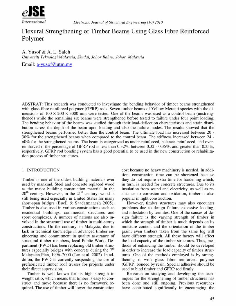
Electronic Journal of Structural Engineering (10) 2010
45
1 INTRODUCTION
Timber is one of the oldest building materials ever used by mankind. Steel and concrete replaced wood as the major building construction material in the 20
th century. However, in the 21
st century, wood is
still being used especially in United States for many short-span bridges (Buell & Saadatmanesh 2005). Timber is also used in various constructions such as residential buildings, commercial structures and sport complexes. A number of nations are also in-volved in the structural use of timber in multi-storey constructions. On the contrary, in Malaysia, due to lack in technical knowledge in advanced timber en-gineering and commitment in quality assurance of structural timber members, local Public Works De-partment (PWD) has been replacing old timber struc-tures especially bridges with concrete during the 7
th
Malaysian Plan, 1996–2000 (Tan et al. 2002). In ad-dition, the PWD is currently suspending the use of prefabricated timber roof trusses for projects under their direct supervision.
Timber is well known for its high strength to weight ratio, which means that timber is easy to con-struct and move because there is no formwork re-quired. The use of timber will lower the construction
cost because no heavy machinery is needed. In addi-tion, construction time can be shortened because they do not require extra time for hardening which, in turn, is needed for concrete structures. Due to its insulation from sound and electricity, as well as re-sistance to corrosion and oxidation, timber is also popular in light construction.
However, timber structures may also encounter problems due to design failure, excessive loading, and infestation by termites. One of the causes of de-sign failure is the varying strength of timber in which the strength of timber is much depends on its moisture content and the orientation of the timber grain; even timbers taken from the same log will have different strength. All these factors will affect the load capacity of the timber structures. Thus, me-thods of enhancing the timber should be developed in order to increase the load capacity of timber struc-tures. One of the methods employed is by streng-thening it with glass fibre reinforced polymer (GFRP) bonded by resin. Special adhesive should be used to bind timber and GFRP rod firmly.
Research on studying and developing the tech-niques for the strengthening of timber structures has been done and still ongoing. Previous researches have contributed significantly in encouraging the
Flexural Strengthening of Timber Beams Using Glass Fibre Reinforced Polymer
A. Yusof & A. L. Saleh Universiti Teknologi Malaysia, Skudai, Johor Bahru, Johor, Malaysia
Email: [email protected]
ABSTRAT: This research was conducted to investigate the bending behavior of timber beams strengthened with glass fibre reinforced polymer (GFRP) rods. Seven timber beams of Yellow Meranti species with the di-mensions of 100 × 200 × 3000 mm were tested. One of the beams was used as a control beam (unstreng-thened) while the remaining six beams were strengthened before tested to failure under four point loading. The bending behavior of the beams was studied through their load-deflection characteristics and strain distri-bution across the depth of the beam upon loading and also the failure modes. The results showed that the strengthened beams performed better than the control beam. The ultimate load has increased between 20 - 30% for the strengthened beams when compared to the control beam. The stiffness increased between 24 - 60% for the strengthened beams. The beam is categorized as under-reinforced, balance- reinforced, and over- reinforced if the percentage of GFRP rod is less than 0.32%, between 0.32 - 0.35%, and greater than 0.35%, respectively. GFRP rod bonding system has a good potential to be used in the new construction or rehabilita-tion process of timber structures.
Electronic Journal of Structural Engineering (10) 2010
47
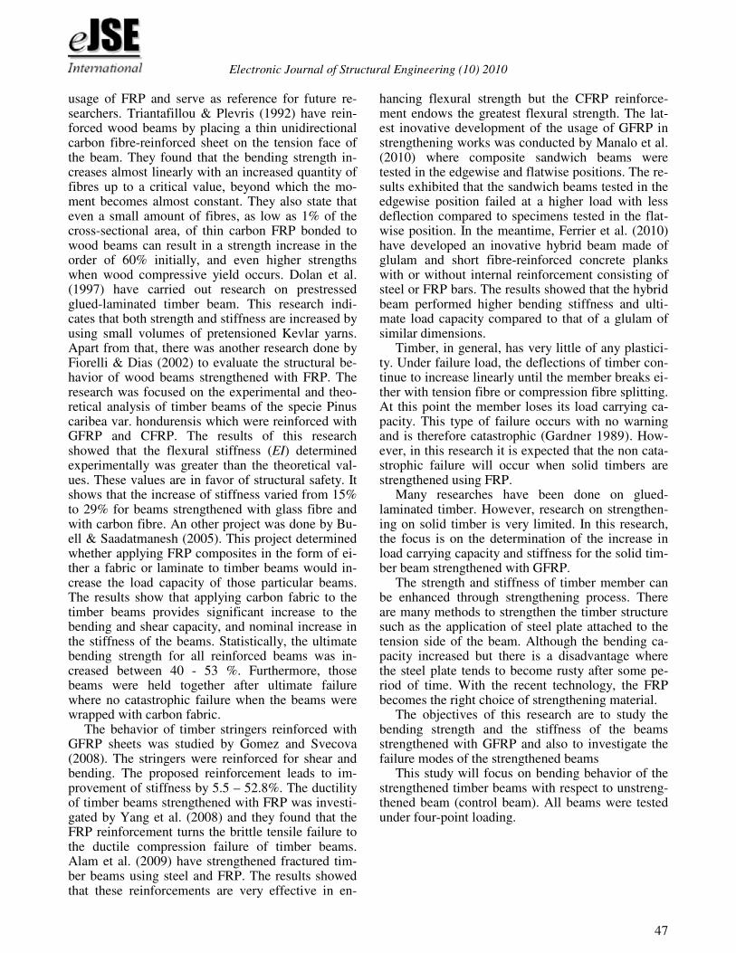
usage of FRP and serve as reference for future re-searchers. Triantafillou & Plevris (1992) have rein-forced wood beams by placing a thin unidirectional carbon fibre-reinforced sheet on the tension face of the beam. They found that the bending strength in-creases almost linearly with an increased quantity of fibres up to a critical value, beyond which the mo-ment becomes almost constant. They also state that even a small amount of fibres, as low as 1% of the cross-sectional area, of thin carbon FRP bonded to wood beams can result in a strength increase in the order of 60% initially, and even higher strengths when wood compressive yield occurs. Dolan et al. (1997) have carried out research on prestressed glued-laminated timber beam. This research indi-cates that both strength and stiffness are increased by using small volumes of pretensioned Kevlar yarns. Apart from that, there was another research done by Fiorelli & Dias (2002) to evaluate the structural be-havior of wood beams strengthened with FRP. The research was focused on the experimental and theo-retical analysis of timber beams of the specie Pinus caribea var. hondurensis which were reinforced with GFRP and CFRP. The results of this research showed that the flexural stiffness (EI) determined experimentally was greater than the theoretical val-ues. These values are in favor of structural safety. It shows that the increase of stiffness varied from 15% to 29% for beams strengthened with glass fibre and with carbon fibre. An other project was done by Bu-ell & Saadatmanesh (2005). This project determined whether applying FRP composites in the form of ei-ther a fabric or laminate to timber beams would in-crease the load capacity of those particular beams. The results show that applying carbon fabric to the timber beams provides significant increase to the bending and shear capacity, and nominal increase in the stiffness of the beams. Statistically, the ultimate bending strength for all reinforced beams was in-creased between 40 - 53 %. Furthermore, those beams were held together after ultimate failure where no catastrophic failure when the beams were wrapped with carbon fabric.
The behavior of timber stringers reinforced with GFRP sheets was studied by Gomez and Svecova (2008). The stringers were reinforced for shear and bending. The proposed reinforcement leads to im-provement of stiffness by 5.5 – 52.8%. The ductility of timber beams strengthened with FRP was investi-gated by Yang et al. (2008) and they found that the FRP reinforcement turns the brittle tensile failure to the ductile compression failure of timber beams. Alam et al. (2009) have strengthened fractured tim-ber beams using steel and FRP. The results showed that these reinforcements are very effective in en-
hancing flexural strength but the CFRP reinforce- ment endows the greatest flexural strength. The lat-est inovative development of the usage of GFRP in strengthening works was conducted by Manalo et al. (2010) where composite sandwich beams were tested in the edgewise and flatwise positions. The re-sults exhibited that the sandwich beams tested in the edgewise position failed at a higher load with less deflection compared to specimens tested in the flat-wise position. In the meantime, Ferrier et al. (2010) have developed an inovative hybrid beam made of glulam and short fibre-reinforced concrete planks with or without internal reinforcement consisting of steel or FRP bars. The results showed that the hybrid beam performed higher bending stiffness and ulti-mate load capacity compared to that of a glulam of similar dimensions.
Timber, in general, has very little of any plastici-ty. Under failure load, the deflections of timber con-tinue to increase linearly until the member breaks ei-ther with tension fibre or compression fibre splitting. At this point the member loses its load carrying ca-pacity. This type of failure occurs with no warning and is therefore catastrophic (Gardner 1989). How-ever, in this research it is expected that the non cata-strophic failure will occur when solid timbers are strengthened using FRP.
Many researches have been done on glued-laminated timber. However, research on strengthen-ing on solid timber is very limited. In this research, the focus is on the determination of the increase in load carrying capacity and stiffness for the solid tim-ber beam strengthened with GFRP.
The strength and stiffness of timber member can be enhanced through strengthening process. There are many methods to strengthen the timber structure such as the application of steel plate attached to the tension side of the beam. Although the bending ca-pacity increased but there is a disadvantage where the steel plate tends to become rusty after some pe-riod of time. With the recent technology, the FRP becomes the right choice of strengthening material.
The objectives of this research are to study the bending strength and the stiffness of the beams strengthened with GFRP and also to investigate the failure modes of the strengthened beams
This study will focus on bending behavior of the strengthened timber beams with respect to unstreng-thened beam (control beam). All beams were tested under four-point loading.
Electronic Journal of Structural Engineering (10) 2010
48
2 RESEARCH SIGNIFICANCE
When a beam is strengthened at tension zone, the mode of failure for the timber structures may change from tension failures to compression failures. In oth-er words, this method increases the tensile capacity of the structure, as well as fully utilizing the com-pression capacity of timber. As a result, it can be ap-plied in new construction projects, as well as in the rehabilitation of existing timber structures. The re-habilitation and strengthening of the existing timber structures will definitely increase its load capacity and save the cost of timber structure replacement. In addition, effective strengthening techniques will also reduce the size or depth of the timber beams that are required for construction (Haiman & Zagar 2002). Bigger section of timber beams are getting difficult to be obtained, thus small section of timber beams after strengthened can have equivalent capacity as big section.
Yellow Meranti, a widely distributed wood spe-cies in Malaysia, is not a high-performance material for structural usage because of its low strength and durability. Since Yellow Meranti is cheap and used in furniture industry, research has been conducted at UTM to study the feasibility of utilizing the low-grade Yellow Meranti for structural usage by rein-forcing it with FRP composites.
3 RESEARCH MATERIALS
3.1 Yellow Meranti timber beams
The main research material was Yellow Meranti timber beams which obtained from Segamat, Johor. The size of the beam is 100 × 200 × 3000 mm. Yel-low Meranti, also known as yellow seraya is the im-portant commercial light hardwood in Malaysia which is exported as sawn timber and logs (Desch 1981). Table 2.2 in MS 544: PART 2 (2001) catego-rized the strength of Yellow Meranti is in strength group 6 and it requires preservative treatment before being used in construction. However, for this re-search, untreated Yellow Meranti was used.
Yellow Meranti has density between 575 - 735 kg/m
3 at air dry (MTC Wood Wizard 2006). The
average density is 680kg/m3 at 19% of moisture con-
tent (MS 544: PART 2: 2001). The durability of the heartwood can be classified as moderately durable while sapwood of Yellow Meranti is susceptible to powder-post beetle attack. In terms of working quali-ties, Yellow Meranti gives a good finish in most op-erations by hand and machine tools.
3.2 Glass fibre reinforced polymer (GFRP)
The GFRP rods were obtained from Polymer Com-posite Asia at Nilai, Negeri Sembilan. Three sizes of rods were used i.e. 6.35 mm, 9.53 mm and 12.7 mm.
Fibres are the main component in a fibre rein-forced composite material. The primary function of fibres or reinforcements is to carry load along the length of the fibre. Glass fibres are one type of fibres that is considered strong in strength but lack in rigid-ity due to their molecular structure. Whereas, the po-lymer has low tensile strength but high rigidity. Combining these two materials will provide good composite element. GFRP is a brittle material and has low elasticity modulus when compared to steel (Shin 2003). GFRP are available in very long lengths, easy to handle and installed in construction due to its light weight. All FRP materials have the same behavior when subject to tension load. FRP will react elastically in the beginning until final brit-tle rupture.
3.3 Adhesives
The adhesive used to bond the timber and GFRP rods was Sikadur
®-30 which is a product from Sika
Kimia Sdn Bhd. It consists of component A which is white in color and component B which black/grey in color. By mixing these two components where the ratio of A:B is equal to 3:1 either by weight or vo-lume for at least 3 minutes, the mixture becomes smooth in consistency and uniform grey color. It is normally used at temperature between 8
oC to 35
oC.
Table 1 shows the characteristics of Sikadur®
-30.
Table 1. Characteristic of Sikadur-30
Characteristics Sikadur-30
Elastic Modulus (N/mm2) 12,800 (Static) Compressive Strength (N/mm2)
85 – 95 (7 days at +35 o
C)
Tensile Strength (N/mm2) 26 – 31 (7 days at +35
oC)
Shear Strength (N/mm2) 16 – 20 (7 days at +35 oC) Shrinkage(%) 0.04 Pot life (minutes) 40 (at 35
oC)
4 LABORATORY WORKS
Tests were conducted to determine the bending be-havior of strengthened and unstrengthened timber beams. The dimension of timber beam was 100 × 200 × 3000 mm and seven timber beams were taken randomly. The clear span was 2700 mm. All beams were tested in accordance to American Society for Testing and Materials (ASTM: D198-27, 1992).
Electronic Journal of Structural Engineering (10) 2010
49
4.1 Testing of moisture content of timber beams
Since the strength of the timber beams varies with moisture content, it is necessary to determine the moisture content of each timber beam. The preferred result is that all timber beams will have the same moisture content. This is to ensure that the effect of moisture content to the strength can be eliminated. Hence the variation in strength of timber comes from the effect of strengthening. The testing of moisture content was conducted in accordance to ASTM Standards (ASTM: D 4442 – 92, 1992).
4.2 Static bending test of Yellow Meranti specimens
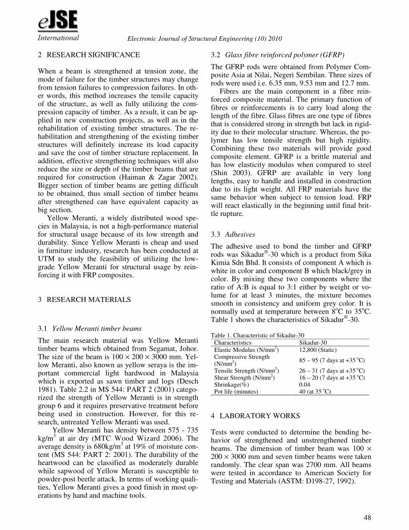
The static bending test was carried out based on BS 373:1957. The dimensions of the sample are 50 mm × 50 mm × 1000 mm. Twelve samples were pre-pared for this test. The distance between the supports and the distance between the applied point load and the support are shown in Figure 1.
The load was applied at such a rate that loading head moves at a constant speed of 0.13 in/min (0.1 in/min in ASTM D143-83). The sample was sup-ported by pin and roller support so that the sample is free to follow the bending action and not be re-strained by friction to avoid any longitudinal stresses due to friction force.
900 mm50 50
50 mm
50 mm
a = 150 mm
P/2 P/2
P/2 P/2l = 500 mm
a = 150 mm
Figure 1. Static bending test: four point loading method
4.3 Tensile test of GFRP rods
The tensile test was carried out in accordance to ASTM D3039. The standard did not mention in de-tails on how to prepare the samples. However, Val-ter et al. (2009) have suggested to use a conical po-lymeric head that fits a conical hole inside the anchoring device at grip heads. Nine samples were prepared for this test. The test was conducted in or-der to determine direct tensile strength, elasticity modulus and stress-strain relationship for GFRP rods due to the lack of information from manufacturer.
4.4 Strengthening of timber beams
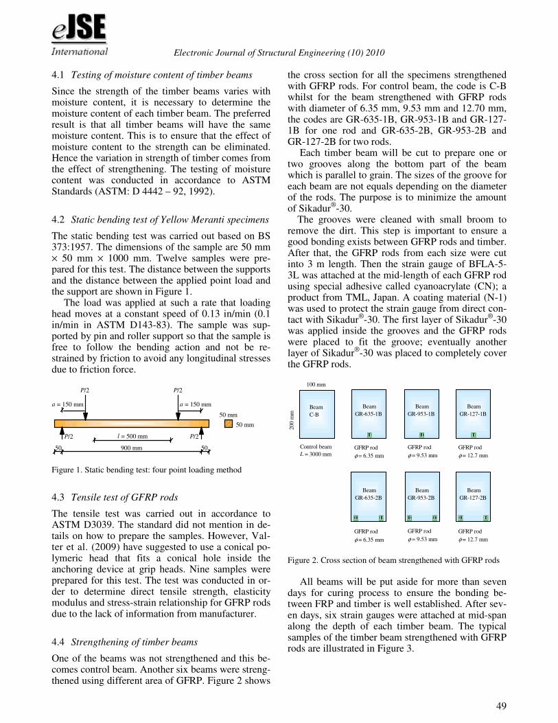
One of the beams was not strengthened and this be-comes control beam. Another six beams were streng-thened using different area of GFRP. Figure 2 shows
the cross section for all the specimens strengthened with GFRP rods. For control beam, the code is C-B whilst for the beam strengthened with GFRP rods with diameter of 6.35 mm, 9.53 mm and 12.70 mm, the codes are GR-635-1B, GR-953-1B and GR-127-1B for one rod and GR-635-2B, GR-953-2B and GR-127-2B for two rods.
Each timber beam will be cut to prepare one or two grooves along the bottom part of the beam which is parallel to grain. The sizes of the groove for each beam are not equals depending on the diameter of the rods. The purpose is to minimize the amount of Sikadur
®-30.
The grooves were cleaned with small broom to remove the dirt. This step is important to ensure a good bonding exists between GFRP rods and timber. After that, the GFRP rods from each size were cut into 3 m length. Then the strain gauge of BFLA-5-3L was attached at the mid-length of each GFRP rod using special adhesive called cyanoacrylate (CN); a product from TML, Japan. A coating material (N-1) was used to protect the strain gauge from direct con-tact with Sikadur
®-30. The first layer of Sikadur
®-30
was applied inside the grooves and the GFRP rods were placed to fit the groove; eventually another layer of Sikadur
®-30 was placed to completely cover
the GFRP rods.
Control beam
L = 3000 mm
100 mm
200 m
m
GFRP rod
φ = 9.53 mm
GFRP rod
φ = 6.35 mm
GFRP rod
φ = 12.7 mm
GFRP rod
φ = 9.53 mm
GFRP rod
φ = 6.35 mm
GFRP rod
φ = 12.7 mm
Beam
C-B
Beam
GR-635-1B
Beam
GR-953-1B
Beam
GR-127-1B
Beam
GR-635-2B
Beam
GR-953-2B
Beam
GR-127-2B
Figure 2. Cross section of beam strengthened with GFRP rods
All beams will be put aside for more than seven
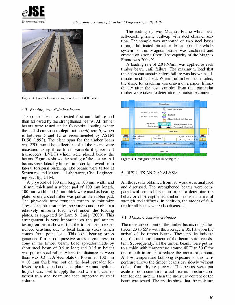
days for curing process to ensure the bonding be-tween FRP and timber is well established. After sev-en days, six strain gauges were attached at mid-span along the depth of each timber beam. The typical samples of the timber beam strengthened with GFRP rods are illustrated in Figure 3.
Electronic Journal of Structural Engineering (10) 2010
50
Figure 3. Timber beam strengthened with GFRP rods
4.5 Bending test of timber beams
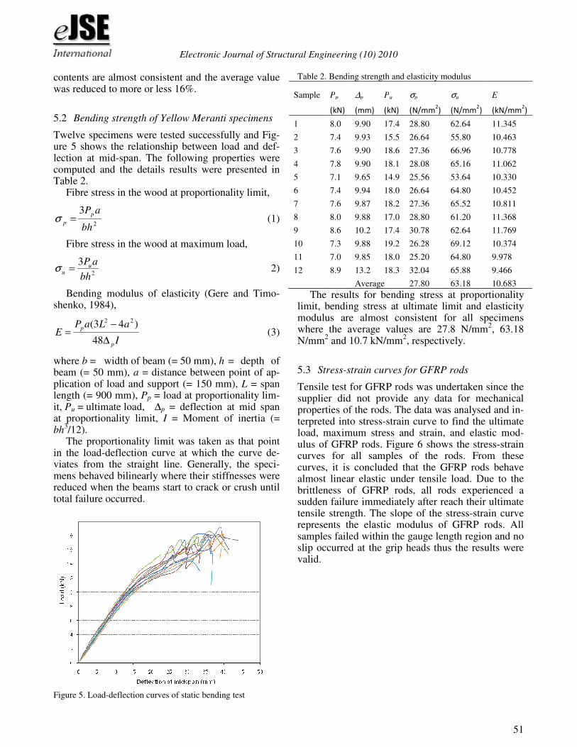
The control beam was tested first until failure and then followed by the strengthened beams. All timber beams were tested under four-point loading where the half shear span to depth ratio (a/h) was 6, which is between 5 and 12 as recommended by ASTM D198 (1992). The clear span for the timber beam was 2700 mm. The deflections of all the beams were measured using three linear variable displacement transducers (LVDT) which were placed below the beams. Figure 4 shows the setting of the testing. All beams were laterally braced in order to prevent from lateral torsional buckling. The beams were tested at Structures and Materials Laboratory, Civil Engineer-ing Faculty, UTM.
A plywood of 100 mm length, 100 mm width and 16 mm thick and a rubber pad of 100 mm length, 100 mm width and 5 mm thick were used as bearing plate before a steel roller was put on the rubber pad. The plywoods were rounded corners to minimize stress concentration in test specimens and to obtain a relatively uniform load level under the loading plates, as suggested by Lam & Craig (2000). This arrangement is very important as the preliminary testing on beam showed that the timber beam expe-rienced crushing due to local bearing stress which comes from point load. This local bearing stress generated further compressive stress at compression zone in the timber beam. Load spreader made by short steel beam of 0.6 m long and 0.15 m height was put on steel rollers where the distance between them was 0.3 m. A steel plate of 100 mm × 100 mm × 10 mm thick was put on the load spreader fol-lowed by a load cell and steel plate. An auto hydrau-lic jack was used to apply the load where it was at-tached to a steel beam and then supported by steel column.
The testing rig was Magnus Frame which was self-reacting frame built-up with steel channel sec-tion. The sample was supported on two steel bases through lubricated pin and roller support. The whole system of this Magnus Frame was anchored and erected on strong floor. The capacity of the Magnus Frame was 200 kN.
A loading rate of 2.0 kN/min was applied to each timber beam until failure. The maximum load that the beam can sustain before failure was known as ul-timate bending load. When the timber beam failed, the shape for cracking was drawn on a paper. Imme-diately after the test, samples from that particular timber were taken to determine its moisture content.
900 mm 300 mm 900 mm300 mm 300 mm 150150
Auto hydraulic jack
Steel plate (10 mm thick)
Load cell
Manual hydraulic jack (Enerpac)
Load spreader
Steel rollerRubber pad (5 mm thick)
Plywood pad (16 mm thick)
Timber beam
Steel plate (10 mm thick)
200
LVDT
(200 mm)Rubber pad (5 mm thick)
Steel rocker/rod
Steel plate
Plywood (16 mm thick)
Magnus Frame
Strong floor
Figure 4. Configuration for bending test
5 RESULTS AND ANALYSIS
All the results obtained from lab work were analyzed and discussed. The strengthened beams were com-pared with control beam in order to determine the behavior of strengthened timber beams in terms of strength and stiffness. In addition, the modes of fail-ure for all beams were also discussed.
5.1 Moisture content of timber
The moisture content of the timber beams ranged be-tween 23 to 65% with the average is 35.1% upon the arrival of the timber beams. These results indicate that the moisture content of the beam is not consis-tent. Subsequently, all the timber beams were put in-to a cabin with temperature around 40
oC to 50
oC for
one month in order to reduce the moisture content. At low temperature but long exposure to this tem-perature allows the timber beams dry slowly without defect from drying process. The beams were put aside at room condition to stabilise its moisture con-tent for one month. Then the moisture content of the beam was tested. The results show that the moisture
Electronic Journal of Structural Engineering (10) 2010
51
contents are almost consistent and the average value was reduced to more or less 16%.
5.2 Bending strength of Yellow Meranti specimens
Twelve specimens were tested successfully and Fig-ure 5 shows the relationship between load and def-lection at mid-span. The following properties were computed and the details results were presented in Table 2.
Fibre stress in the wood at proportionality limit,
2
3
bh
aPp
p =σ (1)
Fibre stress in the wood at maximum load,
2
3
bh
aPuu =σ 2)
Bending modulus of elasticity (Gere and Timo-shenko, 1984),
I
aLaPE
p
p
∆
−=
48
)43( 22
(3)
where b = width of beam (= 50 mm), h = depth of beam (= 50 mm), a = distance between point of ap-plication of load and support (= 150 mm), L = span length (= 900 mm), Pp = load at proportionality lim-it, Pu = ultimate load, ∆p = deflection at mid span at proportionality limit, I = Moment of inertia (= bh
3/12). The proportionality limit was taken as that point
in the load-deflection curve at which the curve de-viates from the straight line. Generally, the speci-mens behaved bilinearly where their stiffnesses were reduced when the beams start to crack or crush until total failure occurred.
Figure 5. Load-deflection curves of static bending test
Table 2. Bending strength and elasticity modulus
Sample Pp ∆p Pu σp σu E
(kN) (mm) (kN) (N/mm2) (N/mm
2) (kN/mm
2)
1 8.0 9.90 17.4 28.80 62.64 11.345
2 7.4 9.93 15.5 26.64 55.80 10.463
3 7.6 9.90 18.6 27.36 66.96 10.778
4 7.8 9.90 18.1 28.08 65.16 11.062
5 7.1 9.65 14.9 25.56 53.64 10.330
6 7.4 9.94 18.0 26.64 64.80 10.452
7 7.6 9.87 18.2 27.36 65.52 10.811
8 8.0 9.88 17.0 28.80 61.20 11.368
9 8.6 10.2 17.4 30.78 62.64 11.769
10 7.3 9.88 19.2 26.28 69.12 10.374
11 7.0 9.85 18.0 25.20 64.80 9.978
12 8.9 13.2 18.3 32.04 65.88 9.466
Average 27.80 63.18 10.683
The results for bending stress at proportionality limit, bending stress at ultimate limit and elasticity modulus are almost consistent for all specimens where the average values are 27.8 N/mm
2, 63.18
N/mm2 and 10.7 kN/mm
2, respectively.
5.3 Stress-strain curves for GFRP rods
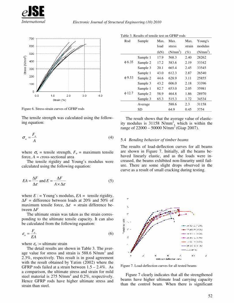
Tensile test for GFRP rods was undertaken since the supplier did not provide any data for mechanical properties of the rods. The data was analysed and in-terpreted into stress-strain curve to find the ultimate load, maximum stress and strain, and elastic mod-ulus of GFRP rods. Figure 6 shows the stress-strain curves for all samples of the rods. From these curves, it is concluded that the GFRP rods behave almost linear elastic under tensile load. Due to the brittleness of GFRP rods, all rods experienced a sudden failure immediately after reach their ultimate tensile strength. The slope of the stress-strain curve represents the elastic modulus of GFRP rods. All samples failed within the gauge length region and no slip occurred at the grip heads thus the results were valid.
Electronic Journal of Structural Engineering (10) 2010
52
Figure 6. Stress-strain curves of GFRP rods
The tensile strength was calculated using the follow-ing equation:
A
Fu
u =σ (4)
where σu = tensile strength, Fu = maximum tensile force, A = cross-sectional area
The tensile rigidity and Young’s modulus were calculated using the following equation:
ε∆
∆=
FEA and
ε∆×
∆=
A
FE (5)
where E : = Young’s modulus, EA = tensile rigidity, ∆F = difference between loads at 20% and 50% of maximum tensile force, ∆ε = strain difference be-tween ∆F
The ultimate strain was taken as the strain corres-ponding to the ultimate tensile capacity. It can also be calculated from the following equation:
EA
Fuu =ε (6)
where εu := ultimate strain The detail results are shown in Table 3. The aver-
age value for stress and strain is 588.6 N/mm2 and
2.3%, respectively. This result is in good agreement with the result obtained by Yatim (2002) where the GFRP rods failed at a strain between 1.5 – 2.4%. As a comparison, the ultimate stress and strain for mild steel material is 275 N/mm
2 and 0.2%, respectively.
Hence GFRP rods have higher ultimate stress and strain than steel.
Table 3. Results of tensile test on GFRP rods
Rod Sample Max. Max. Max. Young's
load stress strain modulus
(kN) (N/mm2) (%) (N/mm
2)
φ 6.35
Sample 1 17.9 568.3 2.40 28262
Sample 2 17.2 583.6 2.19 33342
Sample 3 20.1 665.4 2.45 33545
φ 9.53
Sample 1 43.0 612.3 2.87 26540
Sample 2 44.6 628.9 3.11 25855
Sample 3 43.2 606.0 2.18 33396
φ 12.7
Sample 1 82.7 653.0 2.05 35981
Sample 2 58.9 464.8 1.86 28970
Sample 3 65.3 515.3 1.72 34534
Average 588.6 2.3 31158
SD 64.9 0.45 3754
The result shows that the average value of elastic-
ity modulus is 31158 N/mm2, which is within the
range of 22000 – 50000 N/mm2
(Giap 2007).
5.4 Bending behavior of timber beams
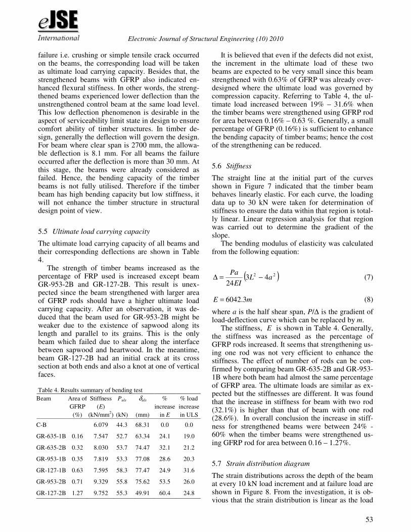
The results of load-deflection curves for all beams are shown in Figure 7. Initially, all the beams be-haved linearly elastic, and as the loads were in-creased, the beams exhibited non-linearity until fail-ure. There are some slight drops observed in the curve as a result of small cracking during testing.
Figure 7. Load-deflection curves for all tested beams
Figure 7 clearly indicates that all the strengthened
beams have higher ultimate load carrying capacity than the control beam. When there is significant
Electronic Journal of Structural Engineering (10) 2010
53
failure i.e. crushing or simple tensile crack occurred on the beams, the corresponding load will be taken as ultimate load carrying capacity. Besides that, the strengthened beams with GFRP also indicated en-hanced flexural stiffness. In other words, the streng-thened beams experienced lower deflection than the unstrengthened control beam at the same load level. This low deflection phenomenon is desirable in the aspect of serviceability limit state in design to ensure comfort ability of timber structures. In timber de-sign, generally the deflection will govern the design. For beam where clear span is 2700 mm, the allowa-ble deflection is 8.1 mm. For all beams the failure occurred after the deflection is more than 30 mm. At this stage, the beams were already considered as failed. Hence, the bending capacity of the timber beams is not fully utilised. Therefore if the timber beam has high bending capacity but low stiffness, it will not enhance the timber structure in structural design point of view.
5.5 Ultimate load carrying capacity
The ultimate load carrying capacity of all beams and their corresponding deflections are shown in Table 4.
The strength of timber beams increased as the percentage of FRP used is increased except beam GR-953-2B and GR-127-2B. This result is unex-pected since the beam strengthened with larger area of GFRP rods should have a higher ultimate load carrying capacity. After an observation, it was de-duced that the beam used for GR-953-2B might be weaker due to the existence of sapwood along its length and parallel to its grains. This is the only beam which failed due to shear along the interface between sapwood and heartwood. In the meantime, beam GR-127-2B had an initial crack at its cross section at both ends and also a knot at one of vertical faces. Table 4. Results summary of bending test
Beam
Area of
GFRP
(%)
Stiffness
(E)
(kN/mm2)
Puls
(kN)
δuls
(mm)
%
increase
in E
% load
increase
in ULS
C-B 6.079 44.3 68.31 0.0 0.0
GR-635-1B 0.16 7.547 52.7 63.34 24.1 19.0
GR-635-2B 0.32 8.030 53.7 74.47 32.1 21.2
GR-953-1B 0.35 7.819 53.3 77.08 28.6 20.3
GR-127-1B 0.63 7.595 58.3 77.47 24.9 31.6
GR-953-2B 0.71 9.329 55.8 75.62 53.5 26.0
GR-127-2B 1.27 9.752 55.3 49.91 60.4 24.8
It is believed that even if the defects did not exist, the increment in the ultimate load of these two beams are expected to be very small since this beam strengthened with 0.63% of GFRP was already over-designed where the ultimate load was governed by compression capacity. Referring to Table 4, the ul-timate load increased between 19% – 31.6% when the timber beams were strengthened using GFRP rod for area between 0.16% – 0.63 %. Generally, a small percentage of GFRP (0.16%) is sufficient to enhance the bending capacity of timber beams; hence the cost of the strengthening can be reduced.
5.6 Stiffness
The straight line at the initial part of the curves shown in Figure 7 indicated that the timber beam behaves linearly elastic. For each curve, the loading data up to 30 kN were taken for determination of stiffness to ensure the data within that region is total-ly linear. Linear regression analysis for that region was carried out to determine the gradient of the slope.
The bending modulus of elasticity was calculated from the following equation:
( )22 4324
aLEI
Pa−=∆ (7)
mE 3.6042= (8)
where a is the half shear span, P/∆ is the gradient of load-deflection curve which can be replaced by m.
The stiffness, E is shown in Table 4. Generally, the stiffness was increased as the percentage of GFRP rods increased. It seems that strengthening us-ing one rod was not very efficient to enhance the stiffness. The effect of number of rods can be con-firmed by comparing beam GR-635-2B and GR-953-1B where both beam had almost the same percentage of GFRP area. The ultimate loads are similar as ex-pected but the stiffnesses are different. It was found that the increase in stiffness for beam with two rod (32.1%) is higher than that of beam with one rod (28.6%). In overall conclusion the increase in stiff-ness for strengthened beams were between 24% - 60% when the timber beams were strengthened us-ing GFRP rod for area between 0.16 – 1.27%.
5.7 Strain distribution diagram
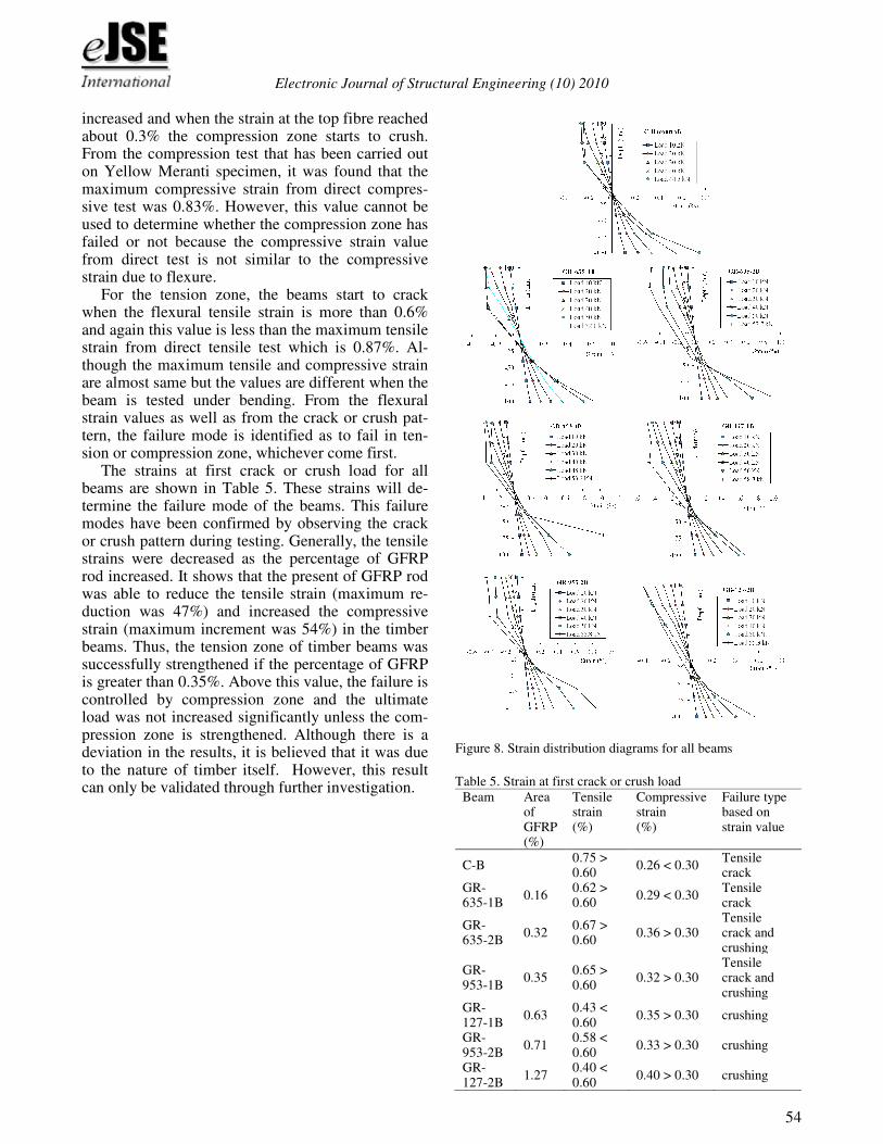
The strain distributions across the depth of the beam at every 10 kN load increment and at failure load are shown in Figure 8. From the investigation, it is ob-vious that the strain distribution is linear as the load
Electronic Journal of Structural Engineering (10) 2010
54
increased and when the strain at the top fibre reached about 0.3% the compression zone starts to crush. From the compression test that has been carried out on Yellow Meranti specimen, it was found that the maximum compressive strain from direct compres-sive test was 0.83%. However, this value cannot be used to determine whether the compression zone has failed or not because the compressive strain value from direct test is not similar to the compressive strain due to flexure.
For the tension zone, the beams start to crack when the flexural tensile strain is more than 0.6% and again this value is less than the maximum tensile strain from direct tensile test which is 0.87%. Al-though the maximum tensile and compressive strain are almost same but the values are different when the beam is tested under bending. From the flexural strain values as well as from the crack or crush pat-tern, the failure mode is identified as to fail in ten-sion or compression zone, whichever come first.
The strains at first crack or crush load for all beams are shown in Table 5. These strains will de-termine the failure mode of the beams. This failure modes have been confirmed by observing the crack or crush pattern during testing. Generally, the tensile strains were decreased as the percentage of GFRP rod increased. It shows that the present of GFRP rod was able to reduce the tensile strain (maximum re-duction was 47%) and increased the compressive strain (maximum increment was 54%) in the timber beams. Thus, the tension zone of timber beams was successfully strengthened if the percentage of GFRP is greater than 0.35%. Above this value, the failure is controlled by compression zone and the ultimate load was not increased significantly unless the com-pression zone is strengthened. Although there is a deviation in the results, it is believed that it was due to the nature of timber itself. However, this result can only be validated through further investigation.
Figure 8. Strain distribution diagrams for all beams
Table 5. Strain at first crack or crush load
Beam
Area of GFRP (%)
Tensile strain (%)
Compressive strain (%)
Failure type based on strain value
C-B 0.75 > 0.60
0.26 < 0.30 Tensile crack
GR-635-1B
0.16 0.62 > 0.60
0.29 < 0.30 Tensile crack
GR-635-2B
0.32 0.67 > 0.60
0.36 > 0.30 Tensile crack and crushing
GR-953-1B
0.35 0.65 > 0.60
0.32 > 0.30 Tensile crack and crushing
GR-127-1B
0.63 0.43 < 0.60
0.35 > 0.30 crushing
GR-953-2B
0.71 0.58 < 0.60
0.33 > 0.30 crushing
GR-127-2B
1.27 0.40 < 0.60
0.40 > 0.30 crushing
Electronic Journal of Structural Engineering (10) 2010
55
5.8 Mode of failure
Table 6 shows the details of mode of failure. Control beam failed in bending with simple tensile crack which shows that the tension capacity is less than the compression capacity for an unstrengthened timber beam. Beam GR-635-1B failed with the same failure mode as control beam, which indicates that the rein-forcement is still inadequate to increase the tension capacity more than compression capacity. Hence the beams can be considered as under-reinforced.
Table 6. Modes of failure for all timber beams
For beam GR-635-2B, minor crushing occurred
shows that the beam was successfully strengthened by GFRP rod of 0.32%. Moreover, the beam failed in crushing followed by simple tensile crack failure. Since the failure in the tension and compression zone occurred almost simultaneously, the beams can be considered as balance-reinforced. Beam GR-953-1B failed with similar pattern to beam GR-635-2B as expected since the area of GFRP for beam GR-953-1B which is 0.35% is almost close to the area of beam GR-635-2B. The other beams show crushing failure occurred first before tension failure. This phenomenon shows that any further increases of GFRP area more than 0.35% yields to be over-reinforced beam. Horizontal shear failure occurred in beam GR-953-2B before the ultimate load was achieved and this phenomenon is due to the separa-tion between heartwood and sapwood. Otherwise beam GR-953-2B is expected to fail in pure bending. Regardless how the beam failed, the GFRP rods were still strongly intact with the timber for all beams and the adhesive was not cracked. Although few cracks were observed on the adhesive but it caused by the wood splitting.
For all beams, before the total failure occurs, sounds of cracking are heard. This characteristic has make timber a suitable construction material that show signs prior to failure. Strengthened timber beams behaved elasto-plastically and held together with the reinforcement after failures occurred.
6 CONCLUSIONS
All Yellow Meranti timber beams were successfully tested. Timber beam strengthened with GFRP rods had an increase in its ultimate load carrying capacity. The percentage of increase is between 20 % - 30 %. The strengthening of timber beams with GFRP en-hanced the stiffness of the beam with a percentage of increase between 24% - 60%. No debonding or de-lamination occurred between GFRP rods and timber
beams. It shows that the load carrying capacity is to-tally dependent on the strength of timber and GFRP. The failure mode was governed by the strength of timber beams since no rupture occurred to the GFRP rods. Sikadur
®-30 showed good performance as a
bonding agent between GFRP rods and timber beams. The timber beams failed in tension when the flexural tensile strain is more than 0.6% whilst the beams failed in compression when the flexural com-pressive strain is more than 0.3%. The failure mode of the strengthened timber beams changed from ten-sion failure to compression failure when the percen-tage of GFRP rod is greater than 0.35%. The beam is
categorized as under-reinforced, balance- reinforced, and over- reinforced if the percentage of GFRP rod is less than 0.32%, between 0.32% - 0.35%, and greater than 0.35%, respectively. The strengthening of timber beam with GFRP rods is a suitable method that can be applied in either new construction or re-habilitation of existing timber structure. However, more tests are required to validate this result before it can be used in design.
Further research on the use of CFRP plate to strengthen the timber beams is recommended since the strength of CFRP is higher than GFRP and also easy to attach to timber beams without the need of the grooves. Although CFRP is another strengthen-ing material, one must consider the cost because they are quite expensive.
ACKNOWLEDGEMENTS
We gratefully acknowledge the support of the Minis-try of Higher Education (MOHE) through Funda-mental Research Grant Scheme (FRGS – Vot 78019)
Beam Area of GFRP
Failure mode
C-B Failed in bending with simple tensile crack (under-reinforced)
GR-635-1B
0.16% Failed in bending with simple tensile crack (under-reinforced)
GR-635-2B
0.32% Crushing and simple tensile crack oc-curred simultaneously (balance-reinforced)
GR-953-1B
0.35% Minor crushing followed by simple tensile crack (balance-reinforced)
GR-127-1B
0.63% Crushing followed by simple tensile crack (over-reinforced)
GR-953-2B
0.71%
Crushing followed by simple tensile crack and lastly sudden horizontal shear failure occurred (over-reinforced)
GR-127-2B
1.27% Crushing followed by simple tensile crack (over-reinforced)
Electronic Journal of Structural Engineering (10) 2010
56
and Research Management Centre (RMC) through Initial Research Grant Scheme (IRGS – Vot 78150) in performing this research.
REFERENCES
Alam, P., Ansell, M.P., and Smedley, D., “Mechanical Repair of Timber Beams Fractured in Flexure Using Bonded-in Reinforcements”, Journal of Composites: Part B. Vol. 40, 2009, pp 95-106
American Society for Testing and Materials (ASTM), 1992, Standard Methods of Static Test of Timbers in structural Sizes, Race St. Philadelphia, ASTM : D198 – 84.
American Society for Testing and Materials (ASTM), 1992, Standard Test Methods for Direct Moisture Content Mea-
surement of Wood and Wood-Base Materials, Race St. Phil-adelphia, ASTM : D4442 – 92.
American Society for Testing and Materials (ASTM), 1992, Standard Methods of Testing Small Clear Specimens of
Timber, Race St. Philadelphia, ASTM : D143-83. British Standards Institution BS 373 (1957). Methods of Testing
Small Clear Specimens of Timber. London: British Stan-dards Institution.
British Standards Institution ISO/DIS.10406-2 (2007). Test
Method for Tensile Properties. London: British Standards Institution
Buell, T.W., and Saadatmanesh, H., “Strengthening Timber Bridge Beams Using Carbon Fibre”, Journal of Structural Engineering, 131(1), 2005, pp 173-187.
Desch, H.E., TIMBER: Its Structure, Properties and Utilisa-
tion, 6th
edi. London, The Macmillan Press Ltd., 1981. Dolan, C.W., Galloway, T.L., and Tsunemori, A., “Prestressed
Glued-Laminated Timber Beam – Pilot Study”, Journal of Composites for Construction. Vol. 1, 1997, pp 1-38.
Ferrier, E., Labossiere, P., and Neale, K.W., “Mechanical Be-havior of an Inovative Hybrid Beam Made of Glulam and Ultrahigh-Performance Concrete Reinforced with FRP or Steel”, Journal of Composites for Construction. Vol. 14, 2010, pp 217-223
Fiorelli, J., Dias, A.A., “Evaluation of the Structural Behavior of Wood Beams Reinforced with FRP”, The Proceedings of 7
th World Conference on Timber Engineering, WCTE 2002,
Perpustakaan Negara Malaysia, August 2002, pp 225-262. Giap, L.H., “Behavior of Timber Beams Strengthened with Fi-
bre Reinforced Polymer”, Tesis Sarjana Muda Kejuruteraan Awam, UTM, 2007.
Gardner, G. P., “A Reinforced Glued Laminated Timber Sys-tem”, 2
nd Pacific Timber Engineering Conference, Volume
2, 1989. Gere, J.M., and Timoshenko, S.P., (2
nd Edition), 1994, Me-
chanics of Materials,. PWS Engineering, Boston, Massa-chusetts.
Gomez, S., and Svecova, D., “Behavior of Split Timber Strin-gers Reinforced eith External GFRP Sheets”, Journal of Composites for Construction. Vol. 12, 2008, pp 202-211
Guan, Z.W., Rodd, P.O., and Pope, D.J., “Study of glulam beams pre-stressed with pultruded GRP”, Journal of Com-posite Structures. Vol 83, 2005, pp 2476-2487.
Haiman, M., Zagar, Z., “Strengthening the Timber Glulam Beams with FRP Plates”, The Proceedings of 7
th World
Conference on Timber Engineering, WCTE 2002, Perpusta-kaan Negara Malaysia, August 2002, pp 270-276.
Lam, F., and Craig, B.A., “Shear Strength in Structural Com-posite Lumber” Journal of Materials in Civil Engineering. Vol 12, 2000, pp 196-204.
Malaysian Standard, Code of Practice for Structural Use of Timber: Part 2, Permissible Stress Design of Solid Timber, Malaysia, MS544, 2001.
Manalo, A.C., Aravinthan, T., Karunasena, W., and Islam, M.M., “Flexural Behavior of Structural Fibre Composite Sandwich Beams in Flatwise and Edgewise Positions” Jour-nal of Composite Structures. Vol 92, 2010, pp 984-995.
MTC Wood Wizard, Malaysian Timber Council, [email protected], 2006
Shin, F.T., “Kelakuan Lenturan Rasuk Komposit GFRP Pul-truded” Tesis Sarjana Muda Kejuruteraan Awam, UTM, 2003.
Tan, Y. E., Zamin, J., and Chai, K. F., “Flexural Behaviour of Visually Strength Graded Glued-Lainated Meranti Beam”, The 7
th World Conference on Timber Engineering, WCTE,
2002. Triantafillou, T.C., and Plevris, N., “FRP-Reinforced Wood as
Structural Material”, Journal of Materials in Civil Engineer-ing. ASCE, Vol 4(3), 1992, pp 300.
Valter, C., Giulia, F., and Marco, A.P., “Anchor System for Tension Testing of Large Diameter GFRP bars”, Journal of Composites for Construction. Vol. 13, 2009, pp 344-349
Yang, H.F., Liu, W.Q., Shao, J.S., and Zhou, Z.H., “Study on Flexural Behavior of Timber Beams Strengthened with FRP”, Journal of Building Materials. Vol. 11, 2008, pp 591-597
Yatim, J., “Performance of Pultruded GFRP Composites Under Tropical Climate”, Phd Thesis, UTM, 2002.