Embed Size (px)
Citation preview
INTERNATIONAL JOURNAL OF CIVIL AND STRUCTURAL ENGINEERING
Volume 2, No 1, 2011
© Copyright 2010 All rights reserved Integrated Publishing services
Research article ISSN 0976 – 4399
Received on July 2011 published on September 2011 138
Flexural behaviour of reinforced Geopolymer concrete beams Dattatreya J K1, Rajamane NP2, Sabitha D1, Ambily P S1, Nataraja MC3
1- Scientists, Advanced Materials Laboratory, CSIR-Structural Engineering Research Centre (SERC), Taramani, Chennai
2-Former Scientist, CSIR-SERC, Chennai, 600113, India 3- Professor, Dept. of Civil Engineering, SJCE, Mysore 570 006, India
ABSTRACT
Efforts are urgently underway all over the world to develop environmentally friendly construction materials, which make minimum utility of fast dwindling natural resources and help to reduce greenhouse gas emissions. In this connection, Geopolymers are showing great potential and several researchers have critically examined the various aspects of their viability as binder system. Geopolymer concretes (GPCs) are new class of building materials that have emerged as an alternative to Ordinary Portland cement concrete (OPCC) and possess the potential to revolutionize the building construction industry. Considerable research has been carried out on development of Geopolymer concretes (GPCs), which involve heat curing. A few studies have been reported on the use of such GPCs for structural applications. In this paper, studies carried out on the behaviour of room temperature cured reinforced GPC flexural members are reported. A total of eighteen beams were tested in flexure. Three conventional concrete mixes and six GPC mixes of target strength ranging from 17 to 63 MPa and having varying combinations of fly ash and slag in the binder phase were considered. The reinforcement was designed considering a balanced section for the expected characteristic strength. All the specimens were tested under two-point static loading. The studies demonstrated that the load carrying capacity of most of the GPC beams was in most cases marginally more than that of the corresponding conventional OPCC beams. The deflections at different stages including service load and peak load stage were higher for GPC beams. However, the ductility factor was comparable to that of OPCC beams. The studies showed that the conventional RC theory could be used for reinforced GPCC flexural beams for the computation of moment capacity, deflection, and crack width within reasonable limits.
Keywords: Flexural behaviour, reinforced concrete, geopolymer concrete, beams 1. Introduction
The construction industry forms a vital sector of the nation’s economy. Utilization of the industrial by-products in this sector could become an important route for large-scale safe disposal of the industrial wastes and reduction of construction cost. In this regard, direct alkaline activation of industrial wastes, such as fly ash and GGBS, can be employed to produce Geopolymer cements which can be gainfully utilized to manufacture novel concretes for constructions (Davidovits, 1991: Duxson, 2007). This can be considered as a sustainable approach to construction since the internal energy content of these new concretes are much less than that of Ordinary Portland cement based concretes (OPCCs) and by this process Portland cement, one of the largest contributors to green house gas is completely eliminated(Duxson, 2007). OPCCs are found to be less durable in some of the very severe
Flexural behaviour of reinforced Geopolymer concrete beams
Dattatreya J K, Rajamane NP, Sabitha D, Ambily P S, Nataraja MC
International Journal of Civil and Structural Engineering
Volume 2 Issue 1 2011 139
environmental conditions; therefore there is a need for development of alternative concretes. The extensive research works carried out by several investigators corroborate the potential of GPC as a prospective construction material (Davidovits, 1991: Duxson, 2007: Harjito and Rangan, 2005, Bakharev,2005: Palomo, 1999:Van Jaarsveld et al.,2002a,Sofi et al., 2006). The development of alternative concretes is of great relevance to India, where the construction industry is in a boom and large quantities of industrial wastes are being generated by the allied industries. Realizing this potential, the CSIR-Structural Engineering Research Centre has carried considerable research on different aspects of Geopolymer concretes (GPCs) for more than 10 years (Rajamane et al., 2005, Dattatreya et al., 2009). The use of GPC is slowly gaining acceptance, especially for chemical resistant structures and research in this area has gained some momentum to extend the range of application. In fact, considerable amount of experimental work has been already carried out in Australia, US and Spain. The previous investigators were mainly engaged in identifying suitable source materials for GPC, their processing, mix design, mechanical properties, and durability aspects(Wallah and Rangan, 2006:Bakharev,2005a, c). The GPC was found to have a high degree of durability when it had inorganic binder based on alumina and silica containing materials like fly ash and GGBS4. But, as in conventional reinforced concretes, the GPC also needs to be reinforced with steel bars for its large scale utility in civil engineering structural applications. Hence, the investigations on behaviour of Reinforced GPC (RGPC) were undertaken. This paper considers reinforced GPC beams with different binder compositions and compressive strengths ranging from 17 to 63 MPa and produced by ambient temperature curing. The RPCC beams based on OPC were also prepared and tested for comparison of performance. A total of eighteen beams consisting of three GPC mixes and three OPCC mixes were tested as part of this study. The beams were designed with 1.82 to 3.33% tension reinforcement (82-110% of corresponding balanced section reinforcement). Performance aspects such as load carrying capacity, moments, deflections, and strains at different stages were studied. The failure modes were also recorded for the beams. The paper compares the performance of RGPC beams vis a vis reinforced Portland cement Concrete (RPCC) beams. 2. Materials and Method
2.1 Materials
Ordinary Portland cement conforming to IS 12269 (with specific gravity of 3.15), fine aggregates, coarse aggregates and potable water were used for the control RPCC test specimens. The RGPC was obtained by mixing different combinations of GGBS, Fly ash, fine aggregates, coarse aggregates and alkaline activator solution (AAS). Fly ash conforming to grade 1 of IS 3812 and GGBS (ground granulated blast furnace slag) from Andhra Cements, Vishakhapatnam conforming to IS 12089 were used. River sand available in Chennai was used as fine aggregates. They were tested as per IS 2386. In this investigation, locally available blue granite crushed stone aggregates of maximum size 12mm and down was used and characterization tests were carried out as per IS 2386. The properties of the materials used are shown in Tables 1 to 5. Potable water was used for the RPCC and distilled water was used for the RGPCs. High strength deformed steel bars with 0.2% proof stress of 450 MPa and nominal diameters of 8mm, 16mm were used as reinforcements in beams.
Flexural behaviour of reinforced Geopolymer concrete beams
Dattatreya J K, Rajamane NP, Sabitha D, Ambily P S, Nataraja MC
International Journal of Civil and Structural Engineering
Volume 2 Issue 1 2011 140
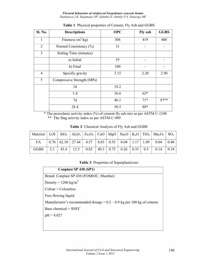
Table 1: Physical properties of Cement, Fly Ash and GGBS
Sl. No. Descriptions OPC Fly ash GGBS
1 Fineness (m2/kg) 306 419 400
2 Normal Consistency (%) 31 - -
3 Setting Time (minutes)
a) Initial 55 - -
b) Final 100 - -
4 Specific gravity 3.15 2.20 2.90
5 Compressive Strength (MPa)
1d 18.2
3 d 36.6 62*
7d 46.1 71* 87**
28 d 58.5 88*
* The pozzolanic activity index (%) of cement-fly ash mix as per ASTM C-1240 ** The Slag activity index as per ASTM C-989
Table 2: Chemical Analysis of Fly Ash and GGBS
Material LOI SiO2 Al2O3 Fe2O3 CaO MgO Na2O K2O TiO2 Mn2O3 SO3
FA 0.76 62.10 27.44 4.57 0.83 0.55 0.04 1.17 1.09 0.04 0.40
GGBS 2.1 43.4 12.5 0.82 40.3 0.75 0.26 0.35 0.5 0.14 0.34
Table 3: Properties of Superplasticizer
Conplast SP 430 (SP1)
Brand: Conplast SP 430 (FOSROC, Mumbai)
Density = 1206 kg/m3
Colour = Colourless
Free flowing liquid
Manufacturer’s recommended dosage = 0.2 – 0.9 kg per 100 kg of cement.
Base chemical = SNFC
pH = 8.027
Flexural behaviour of reinforced Geopolymer concrete beams
Dattatreya J K, Rajamane NP, Sabitha D, Ambily P S, Nataraja MC
International Journal of Civil and Structural Engineering
Volume 2 Issue 1 2011 141
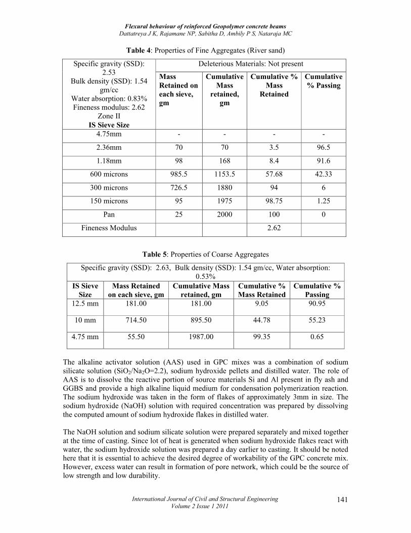
Table 4: Properties of Fine Aggregates (River sand)
Deleterious Materials: Not present Specific gravity (SSD): 2.53
Bulk density (SSD): 1.54 gm/cc
Water absorption: 0.83% Fineness modulus: 2.62
Zone II IS Sieve Size
Mass
Retained on
each sieve,
gm
Cumulative
Mass
retained,
gm
Cumulative %
Mass
Retained
Cumulative
% Passing
4.75mm - - - -
2.36mm 70 70 3.5 96.5
1.18mm 98 168 8.4 91.6
600 microns 985.5 1153.5 57.68 42.33
300 microns 726.5 1880 94 6
150 microns 95 1975 98.75 1.25
Pan 25 2000 100 0
Fineness Modulus 2.62
Table 5: Properties of Coarse Aggregates
Specific gravity (SSD): 2.63, Bulk density (SSD): 1.54 gm/cc, Water absorption: 0.53%
IS Sieve
Size
Mass Retained
on each sieve, gm
Cumulative Mass
retained, gm
Cumulative %
Mass Retained
Cumulative %
Passing
12.5 mm 181.00 181.00 9.05 90.95
10 mm 714.50 895.50 44.78 55.23
4.75 mm 55.50 1987.00 99.35 0.65
The alkaline activator solution (AAS) used in GPC mixes was a combination of sodium silicate solution (SiO2/Na2O=2.2), sodium hydroxide pellets and distilled water. The role of AAS is to dissolve the reactive portion of source materials Si and Al present in fly ash and GGBS and provide a high alkaline liquid medium for condensation polymerization reaction. The sodium hydroxide was taken in the form of flakes of approximately 3mm in size. The sodium hydroxide (NaOH) solution with required concentration was prepared by dissolving the computed amount of sodium hydroxide flakes in distilled water. The NaOH solution and sodium silicate solution were prepared separately and mixed together at the time of casting. Since lot of heat is generated when sodium hydroxide flakes react with water, the sodium hydroxide solution was prepared a day earlier to casting. It should be noted here that it is essential to achieve the desired degree of workability of the GPC concrete mix. However, excess water can result in formation of pore network, which could be the source of low strength and low durability.
Flexural behaviour of reinforced Geopolymer concrete beams
Dattatreya J K, Rajamane NP, Sabitha D, Ambily P S, Nataraja MC
International Journal of Civil and Structural Engineering
Volume 2 Issue 1 2011 142
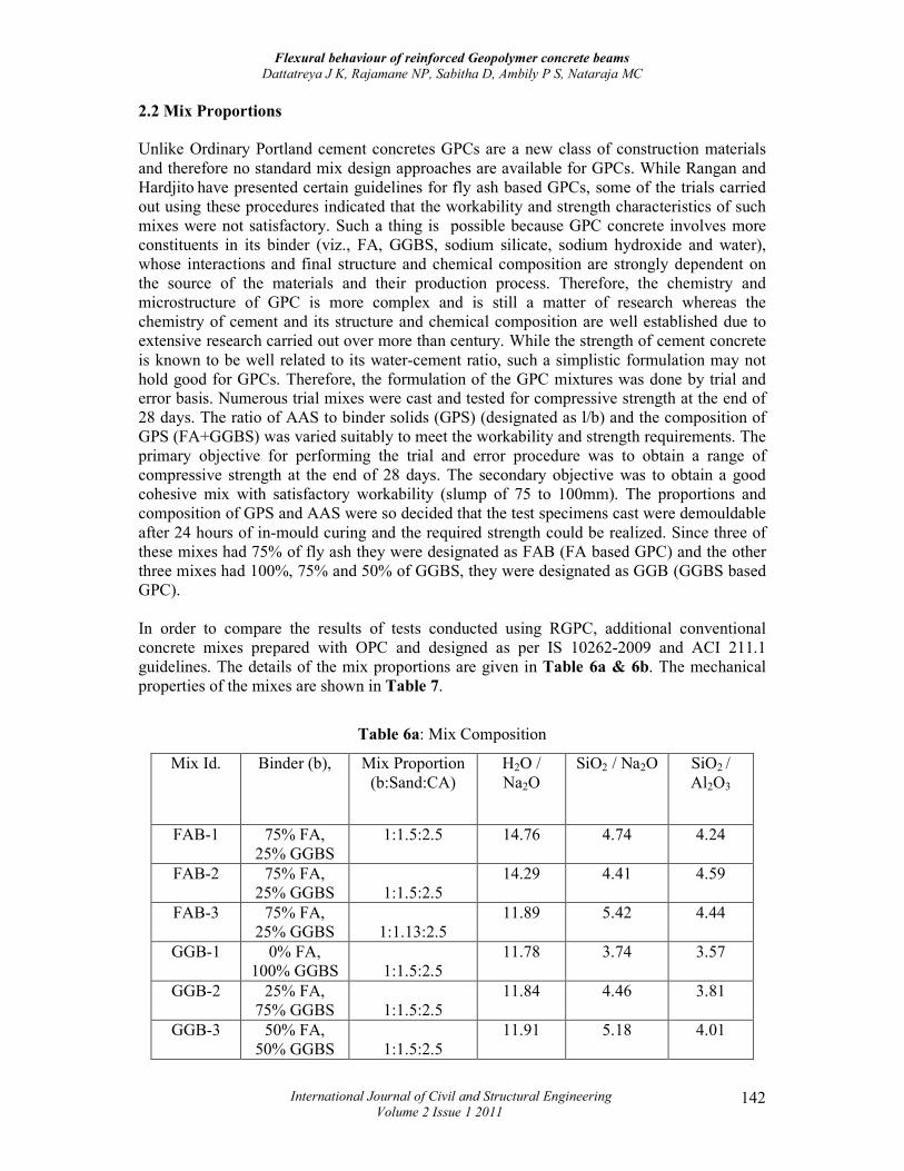
2.2 Mix Proportions
Unlike Ordinary Portland cement concretes GPCs are a new class of construction materials and therefore no standard mix design approaches are available for GPCs. While Rangan and Hardjito have presented certain guidelines for fly ash based GPCs, some of the trials carried out using these procedures indicated that the workability and strength characteristics of such mixes were not satisfactory. Such a thing is possible because GPC concrete involves more constituents in its binder (viz., FA, GGBS, sodium silicate, sodium hydroxide and water), whose interactions and final structure and chemical composition are strongly dependent on the source of the materials and their production process. Therefore, the chemistry and microstructure of GPC is more complex and is still a matter of research whereas the chemistry of cement and its structure and chemical composition are well established due to extensive research carried out over more than century. While the strength of cement concrete is known to be well related to its water-cement ratio, such a simplistic formulation may not hold good for GPCs. Therefore, the formulation of the GPC mixtures was done by trial and error basis. Numerous trial mixes were cast and tested for compressive strength at the end of 28 days. The ratio of AAS to binder solids (GPS) (designated as l/b) and the composition of GPS (FA+GGBS) was varied suitably to meet the workability and strength requirements. The primary objective for performing the trial and error procedure was to obtain a range of compressive strength at the end of 28 days. The secondary objective was to obtain a good cohesive mix with satisfactory workability (slump of 75 to 100mm). The proportions and composition of GPS and AAS were so decided that the test specimens cast were demouldable after 24 hours of in-mould curing and the required strength could be realized. Since three of these mixes had 75% of fly ash they were designated as FAB (FA based GPC) and the other three mixes had 100%, 75% and 50% of GGBS, they were designated as GGB (GGBS based GPC). In order to compare the results of tests conducted using RGPC, additional conventional concrete mixes prepared with OPC and designed as per IS 10262-2009 and ACI 211.1 guidelines. The details of the mix proportions are given in Table 6a & 6b. The mechanical properties of the mixes are shown in Table 7.
Table 6a: Mix Composition
Mix Id. Binder (b), Mix Proportion (b:Sand:CA)
H2O / Na2O
SiO2 / Na2O SiO2 / Al2O3
FAB-1 75% FA, 25% GGBS
1:1.5:2.5 14.76 4.74 4.24
FAB-2 75% FA, 25% GGBS 1:1.5:2.5
14.29 4.41 4.59
FAB-3 75% FA, 25% GGBS 1:1.13:2.5
11.89 5.42 4.44
GGB-1 0% FA, 100% GGBS 1:1.5:2.5
11.78 3.74 3.57
GGB-2 25% FA, 75% GGBS 1:1.5:2.5
11.84 4.46 3.81
GGB-3 50% FA, 50% GGBS 1:1.5:2.5
11.91 5.18 4.01

Flexural behaviour of reinforced Geopolymer concrete beams
Dattatreya J K, Rajamane NP, Sabitha D, Ambily P S, Nataraja MC
International Journal of Civil and Structural Engineering
Volume 2 Issue 1 2011 143
CC1 OPC 1:2.35:2.95 - - - CC2 OPC 1:1.95:2.58 - - - CC3 OPC 1:1.49:2.15 - - -
Table 6b: Mix Composition
Mix Id. Na2O/ (Al2O3+ SiO2)
l/b Na2 O/ GPS, %
SiO2 /GPS
FAB-1 0.17 0.70 11.38 4.28 FAB-2 0.19 0.70 12.47 8.06 FAB-3 0.15 0.55 10.18 6.58 GGB-1 0.21 0.55 9.18 3.45 GGB-2 0.18 0.55 9.18 3.45 GGB-3 0.15 0.55 9.18 3.45
CC1 - 0.55 - - CC2 - 0.48 - - CC3 - 0.40 - -
Note: σcu, 28d Compressive strength, l/b=liquid (AAS)/binder ratio, GPS=binder
+AAS
Table 7: Strength Characteristics of the Mixes
Mix Id. Binder σcu, MPa
σft, MPa
Ec, GPa
σft, MPa (IS-456)
Ec, GPa (IS-456)
Ec, GPa (ACI-318)
CC1 OPC 35 4.03 24.9 3.62 25.86 24.9 CC2 OPC 41 4.32 26.9 4.01 28.61 26.9 CC3 OPC 52 4.85 30.3 4.63 33.07 30.3
FAB-1 75% F, 25% G 17 2.35 11.2 2.07 14.79 14.7 FAB-2 75% F ,25%G 49 4.65 20.8 4.47 31.92 25.0 FAB-3 75% F, 25% G 52 4.81 22.4 4.63 33.07 25.8 GGB-1 0% F, 100%G 63 5.53 28.3 5.18 37.00 28.4 GGB-2 25% F, 75% G 57 4.84 26.5 4.89 34.91 27.0 GGB-3 50% F, 50%G 52 4.86 22.7 4.63 33.07 25.8
Note : σcu,, σspt, σft Ec = Compressive strength, split tensile and flexural tensile strength and elastic modulus 2.3 Specimen Details
The beam specimens were 100mm wide and 150mm deep in cross-section. They were 1500mm in length and simply-supported over an effective span of 1350mm. The clear cover of the beam was 20mm. The geometry of the beam specimen is shown in Figure 1.
Figure 1: Geometry of beam specimen (All dimensions are in mm)
Flexural behaviour of reinforced Geopolymer concrete beams
Dattatreya J K, Rajamane NP, Sabitha D, Ambily P S, Nataraja MC
International Journal of Civil and Structural Engineering
Volume 2 Issue 1 2011 144
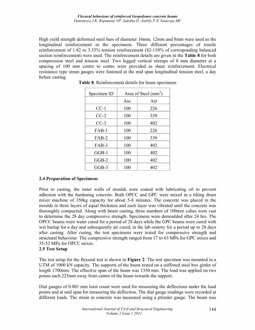
High yield strength deformed steel bars of diameter 16mm, 12mm and 8mm were used as the longitudinal reinforcement in the specimens. Three different percentages of tensile reinforcement of 1.82 to 3.33% tension reinforcement (82-110% of corresponding balanced section reinforcement) were used. The reinforcement details are given in the Table 8 for both compression steel and tension steel. Two legged vertical stirrups of 8 mm diameter at a spacing of 100 mm centre to centre were provided as shear reinforcement. Electrical resistance type strain gauges were fastened at the mid span longitudinal tension steel, a day before casting.
Table 8: Reinforcement details for beam specimens
Specimen ID Area of Steel (mm2)
Asc Ast
CC-1 100 226
CC-2 100 339
CC-3 100 402
FAB-1 100 226
FAB-2 100 339
FAB-3 100 402
GGB-1 100 402
GGB-2 100 402
GGB-3 100 402
2.4 Preparation of Specimens
Prior to casting, the inner walls of moulds were coated with lubricating oil to prevent adhesion with the hardening concrete. Both OPCC and GPC were mixed in a tilting drum mixer machine of 350kg capacity for about 5-8 minutes. The concrete was placed in the moulds in three layers of equal thickness and each layer was vibrated until the concrete was thoroughly compacted. Along with beam casting, three numbers of 100mm cubes were cast to determine the 28 day compressive strength. Specimens were demoulded after 24 hrs. The OPCC beams were water cured for a period of 28 days while the GPC beams were cured with wet burlap for a day and subsequently air cured, in the lab oratory for a period up to 28 days after casting. After curing, the test specimens were tested for compressive strength and structural behaviour. The compressive strength ranged from 17 to 63 MPa for GPC mixes and 35-52 MPa for OPCC mixes. 2.5 Test Setup
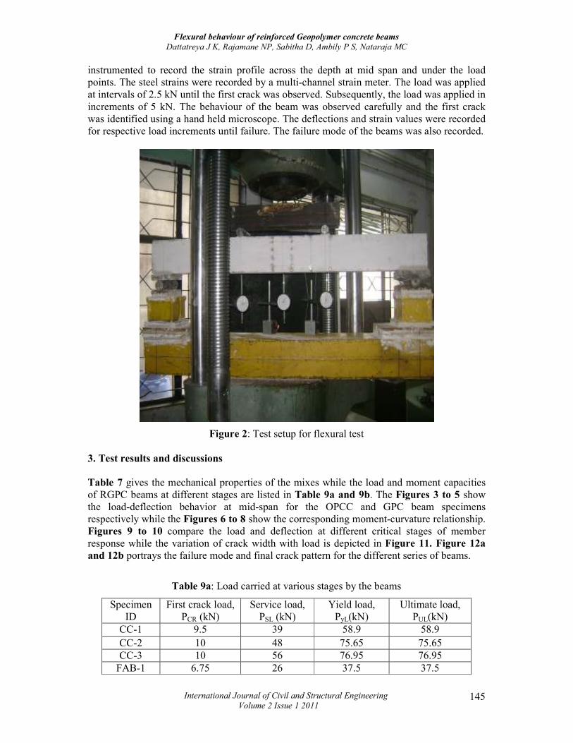
The test setup for the flexural test is shown in Figure 2. The test specimen was mounted in a UTM of 1000 kN capacity. The supports of the beam rested on a stiffened steel box girder of length 1700mm. The effective span of the beam was 1350 mm. The load was applied on two points each 225mm away from centre of the beam towards the support. Dial gauges of 0.001 mm least count were used for measuring the deflections under the load points and at mid span for measuring the deflection. The dial gauge readings were recorded at different loads. The strain in concrete was measured using a pfender gauge. The beam was
Flexural behaviour of reinforced Geopolymer concrete beams
Dattatreya J K, Rajamane NP, Sabitha D, Ambily P S, Nataraja MC
International Journal of Civil and Structural Engineering
Volume 2 Issue 1 2011 145
instrumented to record the strain profile across the depth at mid span and under the load points. The steel strains were recorded by a multi-channel strain meter. The load was applied at intervals of 2.5 kN until the first crack was observed. Subsequently, the load was applied in increments of 5 kN. The behaviour of the beam was observed carefully and the first crack was identified using a hand held microscope. The deflections and strain values were recorded for respective load increments until failure. The failure mode of the beams was also recorded.
Figure 2: Test setup for flexural test
3. Test results and discussions
Table 7 gives the mechanical properties of the mixes while the load and moment capacities of RGPC beams at different stages are listed in Table 9a and 9b. The Figures 3 to 5 show the load-deflection behavior at mid-span for the OPCC and GPC beam specimens respectively while the Figures 6 to 8 show the corresponding moment-curvature relationship. Figures 9 to 10 compare the load and deflection at different critical stages of member response while the variation of crack width with load is depicted in Figure 11. Figure 12a and 12b portrays the failure mode and final crack pattern for the different series of beams.
Table 9a: Load carried at various stages by the beams
Specimen ID
First crack load, PCR (kN)
Service load, PSL (kN)
Yield load, PyL(kN)
Ultimate load, PUL(kN)
CC-1 9.5 39 58.9 58.9 CC-2 10 48 75.65 75.65 CC-3 10 56 76.95 76.95
FAB-1 6.75 26 37.5 37.5
Flexural behaviour of reinforced Geopolymer concrete beams
Dattatreya J K, Rajamane NP, Sabitha D, Ambily P S, Nataraja MC
International Journal of Civil and Structural Engineering
Volume 2 Issue 1 2011 146
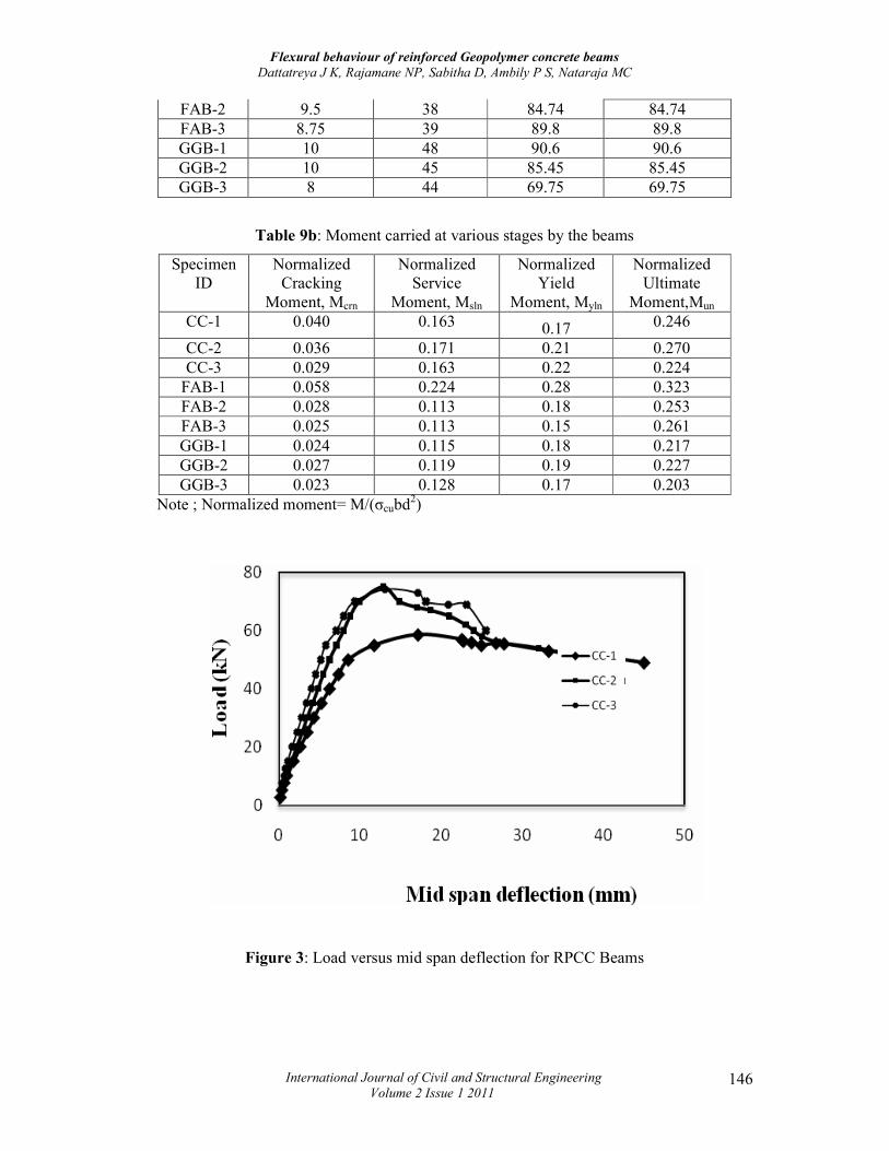
FAB-2 9.5 38 84.74 84.74 FAB-3 8.75 39 89.8 89.8 GGB-1 10 48 90.6 90.6 GGB-2 10 45 85.45 85.45 GGB-3 8 44 69.75 69.75
Table 9b: Moment carried at various stages by the beams
Specimen ID
Normalized Cracking
Moment, Mcrn
Normalized Service
Moment, Msln
Normalized Yield
Moment, Myln
Normalized Ultimate
Moment,Mun CC-1 0.040 0.163 0.17 0.246
CC-2 0.036 0.171 0.21 0.270 CC-3 0.029 0.163 0.22 0.224
FAB-1 0.058 0.224 0.28 0.323 FAB-2 0.028 0.113 0.18 0.253 FAB-3 0.025 0.113 0.15 0.261 GGB-1 0.024 0.115 0.18 0.217 GGB-2 0.027 0.119 0.19 0.227 GGB-3 0.023 0.128 0.17 0.203
Note ; Normalized moment= M/(σcubd2)
Figure 3: Load versus mid span deflection for RPCC Beams
Flexural behaviour of reinforced Geopolymer concrete beams
Dattatreya J K, Rajamane NP, Sabitha D, Ambily P S, Nataraja MC
International Journal of Civil and Structural Engineering
Volume 2 Issue 1 2011 147
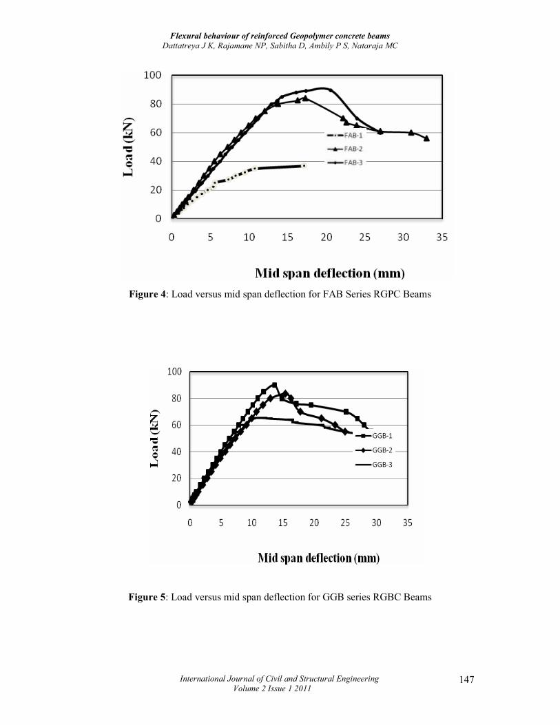
Figure 4: Load versus mid span deflection for FAB Series RGPC Beams
Figure 5: Load versus mid span deflection for GGB series RGBC Beams
Flexural behaviour of reinforced Geopolymer concrete beams
Dattatreya J K, Rajamane NP, Sabitha D, Ambily P S, Nataraja MC
International Journal of Civil and Structural Engineering
Volume 2 Issue 1 2011 148
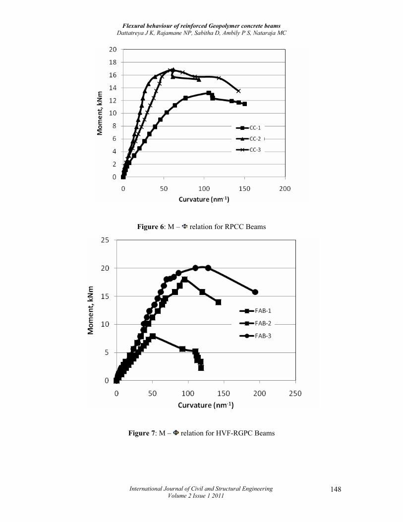
Figure 6: M – relation for RPCC Beams
Figure 7: M – relation for HVF-RGPC Beams
Flexural behaviour of reinforced Geopolymer concrete beams
Dattatreya J K, Rajamane NP, Sabitha D, Ambily P S, Nataraja MC
International Journal of Civil and Structural Engineering
Volume 2 Issue 1 2011 149
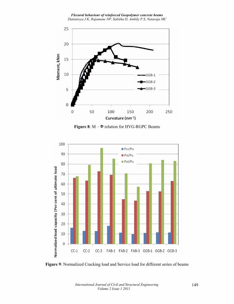
Figure 8: M – relation for HVG-RGPC Beams
Figure 9: Normalized Cracking load and Service load for different series of beams
Flexural behaviour of reinforced Geopolymer concrete beams
Dattatreya J K, Rajamane NP, Sabitha D, Ambily P S, Nataraja MC
International Journal of Civil and Structural Engineering
Volume 2 Issue 1 2011 150
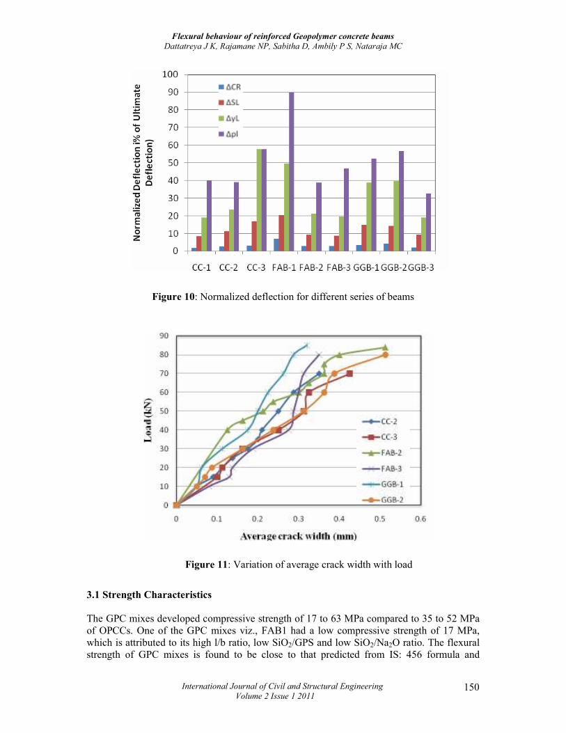
Figure 10: Normalized deflection for different series of beams
Figure 11: Variation of average crack width with load
3.1 Strength Characteristics
The GPC mixes developed compressive strength of 17 to 63 MPa compared to 35 to 52 MPa of OPCCs. One of the GPC mixes viz., FAB1 had a low compressive strength of 17 MPa, which is attributed to its high l/b ratio, low SiO2/GPS and low SiO2/Na2O ratio. The flexural strength of GPC mixes is found to be close to that predicted from IS: 456 formula and

Flexural behaviour of reinforced Geopolymer concrete beams
Dattatreya J K, Rajamane NP, Sabitha D, Ambily P S, Nataraja MC
International Journal of Civil and Structural Engineering
Volume 2 Issue 1 2011 151
compares well with the strength of OPCC specimens (vide Table 7). The elastic modulus is significantly lower for GPCs and ACI 318 prediction seems to be closer to measured elastic modulus compared to IS: 456. This is attributed to the lower aggregate volume fraction of the GPC mixes used. 3.2 Load-deflection Behaviour
The Figures 3 to 5 show the load-deflection behavior at mid-span for the OPCC and GPC beam specimens respectively. The changes in the load-deflection curves clearly indicate the different events occurring during the test. The first visible crack formation occurred at around 10 kN load (about 13-16 % of ultimate load for RPCC and 9-11% for RGPC vide Table 9) registering the first deviation or kink in the curve. Onset of profuse cracking beyond the service load (39-56 kN or about 63-72% for RPCC and 43-63% for RGPC) caused pronounced non-linearity while the yielding of main tensile reinforcement in the load range of 32-74 kN (67-96% for CC series and 57-85% for RPCC beams) led to softening response in some cases and deflection hardening in certain cases depending on the area of reinforcement. The load-deflection pattern was similar in case of RGPC beams as well as RPCC beams except specimen FAB1, which had a very low compressive strength of 17 MPa. A slight drop in the load followed the peak load, in almost all the beams except FAB1 which indicates the disintegration of concrete in the compression zone as a result of buckling of the longitudinal compression steel. The deflection at first crack was less than 1% of ultimate deflection for RPCC beams and slightly more for RGPC beams. The deflection at service load was 8-16% for RPCC and 9 to 20% for RGPC [Table 12]. The deflection at yield ranged from 19 to 57% and 32 to 57% at peak load for both the RPCC and RGPC beams. The better serviceability of RPCC is due to their higher elastic modulus and higher flexural strength. In the case of FAB series beams (FAB-2 and FAB-3), the deflection was about 41-72% more than the RPCC beams at first crack and 33-52% higher at peak load obviously due to their lower elastic modulus. However, the difference was much less in case of GGB series due to their higher compressive strength and hence higher elastic modulus. The deflection of the beams under various loads such as service loads and ultimate loads have been summarized in Table 9. In this study, the service load was reckoned as the load corresponding to a deflection of span/350 or ultimate load divided by load factor 1.5, whichever is less.
3.3 Moment-curvature relations
The curvature at midspan can be computed from sectional analysis by two approaches viz., 1) From the measured deflection using area-moment theorem
(1)
Where,
From the linear strain distribution at midspan as, (2)
While both the approaches give similar results, the second approach was used in the computations in the study as continuous monitoring of all the deflections was not possible in the failure stage. The curves show nearly tri-linear behavior in the pre-peak regime followed by a softening response due to yielding of both tension and compression reinforcement. The changes in slope arise due to reduction in flexural rigidity due to initiation of flexural cracks
Flexural behaviour of reinforced Geopolymer concrete beams
Dattatreya J K, Rajamane NP, Sabitha D, Ambily P S, Nataraja MC
International Journal of Civil and Structural Engineering
Volume 2 Issue 1 2011 152
in the constant bending moment zone and their vertical propagation. RPCC beams show nearly plastic behavior in the post-peak load stage with increasing curvature at almost constant moment where as RGPC beams showed considerable softening in the resisting moment with increase in deflection/curvature indicating a lower residual moment capacity in the post peak regime. The ratio of ultimate curvature (at failure) to curvature at peak load ranged from 1.38 to 2.33 for RPCC beams to 1.47 to 1.75 for GPC, which is indicative of lower post peak ductility of RGPC compared to RPCC. 3.4 Load Capacity at Different stages of Loading
The load capacities at various stages such as, first crack, service load and ultimate stage are summarised in the Table 9 and Figure 9. It is seen that the load at the appearance of first crack was almost the same in the case of RPCC and RGPC beams, despite the slightly higher compressive strength of the RGPC beams. This could be attributed to the marginally lower flexural strength of GPC compared to OPCC probably due to weaker aggregate-paste transition zone and possible shrinkage cracking in the ITZ due to its rapid setting. The first crack load expressed as a fraction of the corresponding ultimate load was distinctly lower for RGPC beams as seen from Figure 9. The RGPC beams also showed lower service load of 43-69% of ultimate load carrying capacity against 63-73% for RPCC beams due to slightly lower flexural rigidity of RGPC. The ultimate load carrying capacity of RGPC beams, except FAB-1 was found to be in the narrow range of 77-90 kN. The ultimate load carrying capacities of the RGPC beams were about 14-17% more than RPCC beams. This could be attributed to their higher compressive strength. As seen from table 10, the normalized moment capacities for RGPC beams were significantly lower with respect to cracking and service load and marginally different in the case of ultimate moment with the exception of low compressive strength beam FAB1. The beam GGB3 showed lower moment capacity than anticipated and this was discovered to be due to lower yield strength and ultimate strength of steel (330 MPa and 430 MPa) used for their production.
3.5 Crack width and crack spacing
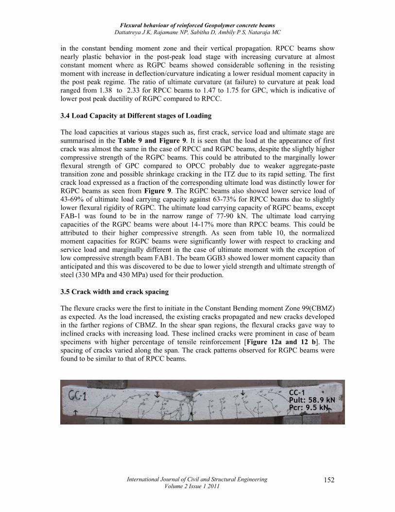
The flexure cracks were the first to initiate in the Constant Bending moment Zone 99(CBMZ) as expected. As the load increased, the existing cracks propagated and new cracks developed in the farther regions of CBMZ. In the shear span regions, the flexural cracks gave way to inclined cracks with increasing load. These inclined cracks were prominent in case of beam specimens with higher percentage of tensile reinforcement [Figure 12a and 12 b]. The spacing of cracks varied along the span. The crack patterns observed for RGPC beams were found to be similar to that of RPCC beams.
Flexural behaviour of reinforced Geopolymer concrete beams
Dattatreya J K, Rajamane NP, Sabitha D, Ambily P S, Nataraja MC
International Journal of Civil and Structural Engineering
Volume 2 Issue 1 2011 153
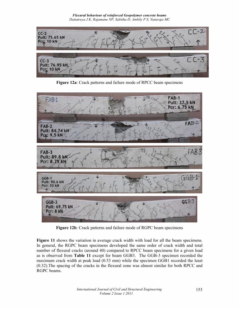
Figure 12a: Crack patterns and failure mode of RPCC beam specimens
Figure 12b: Crack patterns and failure mode of RGPC beam specimens
Figure 11 shows the variation in average crack width with load for all the beam specimens. In general, the RGPC beam specimens developed the same order of crack width and total number of flexural cracks (around 40) compared to RPCC beam specimens for a given load as is observed from Table 11 except for beam GGB3. The GGB-3 specimen recorded the maximum crack width at peak load (0.53 mm) while the specimen GGB1 recorded the least (0.32).The spacing of the cracks in the flexural zone was almost similar for both RPCC and RGPC beams.
Flexural behaviour of reinforced Geopolymer concrete beams
Dattatreya J K, Rajamane NP, Sabitha D, Ambily P S, Nataraja MC
International Journal of Civil and Structural Engineering
Volume 2 Issue 1 2011 154
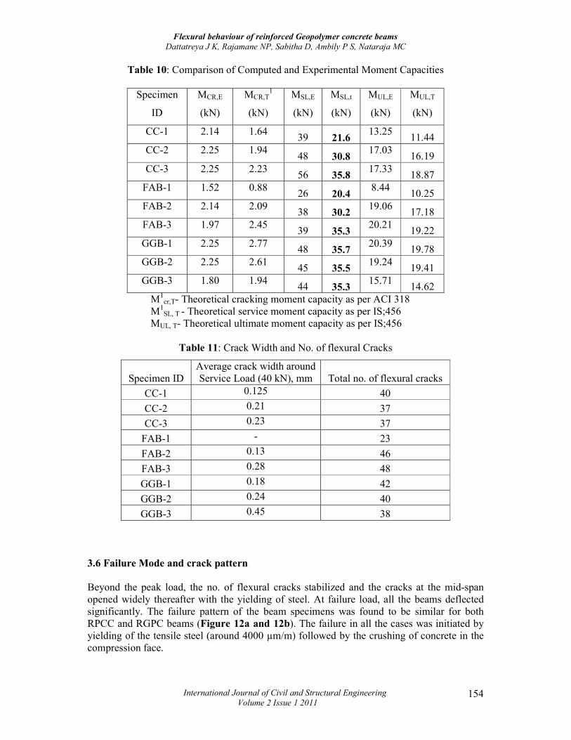
Table 10: Comparison of Computed and Experimental Moment Capacities
Specimen
ID
MCR,E
(kN)
MCR,T1
(kN)
MSL,E
(kN)
MSL,t
(kN)
MUL,E
(kN)
MUL,T
(kN)
CC-1 2.14 1.64 39 21.6
13.25 11.44
CC-2 2.25 1.94 48 30.8
17.03 16.19
CC-3 2.25 2.23 56 35.8
17.33 18.87
FAB-1 1.52 0.88 26 20.4
8.44 10.25
FAB-2 2.14 2.09 38 30.2
19.06 17.18
FAB-3 1.97 2.45 39 35.3
20.21 19.22
GGB-1 2.25 2.77 48 35.7
20.39 19.78
GGB-2 2.25 2.61 45 35.5
19.24 19.41
GGB-3 1.80 1.94 44 35.3
15.71 14.62
M1cr,T- Theoretical cracking moment capacity as per ACI 318
M1SL, T - Theoretical service moment capacity as per IS;456
MUL, T- Theoretical ultimate moment capacity as per IS;456
Table 11: Crack Width and No. of flexural Cracks
Specimen ID Average crack width around Service Load (40 kN), mm Total no. of flexural cracks
CC-1 0.125 40
CC-2 0.21 37
CC-3 0.23 37
FAB-1 - 23
FAB-2 0.13 46
FAB-3 0.28 48
GGB-1 0.18 42
GGB-2 0.24 40
GGB-3 0.45 38
3.6 Failure Mode and crack pattern
Beyond the peak load, the no. of flexural cracks stabilized and the cracks at the mid-span opened widely thereafter with the yielding of steel. At failure load, all the beams deflected significantly. The failure pattern of the beam specimens was found to be similar for both RPCC and RGPC beams (Figure 12a and 12b). The failure in all the cases was initiated by yielding of the tensile steel (around 4000 µm/m) followed by the crushing of concrete in the compression face.
Flexural behaviour of reinforced Geopolymer concrete beams
Dattatreya J K, Rajamane NP, Sabitha D, Ambily P S, Nataraja MC
International Journal of Civil and Structural Engineering
Volume 2 Issue 1 2011 155
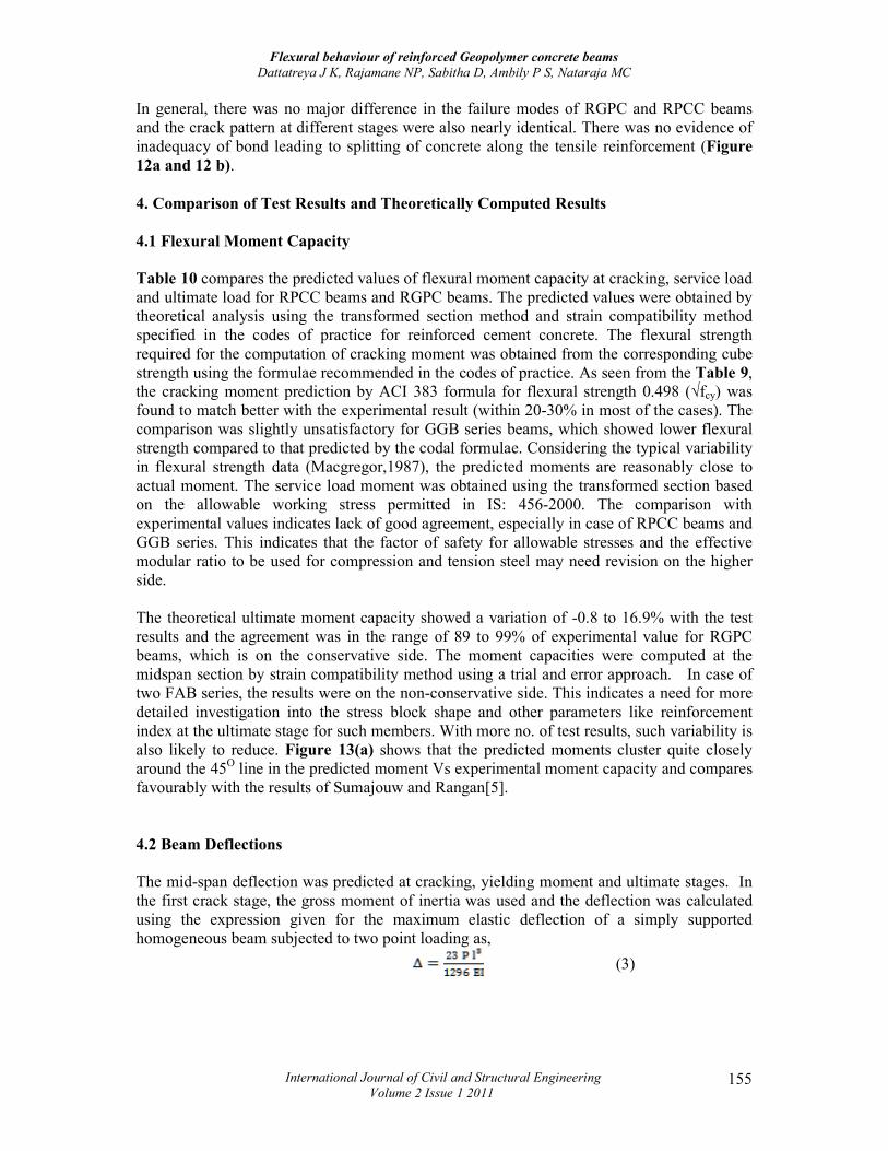
In general, there was no major difference in the failure modes of RGPC and RPCC beams and the crack pattern at different stages were also nearly identical. There was no evidence of inadequacy of bond leading to splitting of concrete along the tensile reinforcement (Figure 12a and 12 b). 4. Comparison of Test Results and Theoretically Computed Results
4.1 Flexural Moment Capacity
Table 10 compares the predicted values of flexural moment capacity at cracking, service load and ultimate load for RPCC beams and RGPC beams. The predicted values were obtained by theoretical analysis using the transformed section method and strain compatibility method specified in the codes of practice for reinforced cement concrete. The flexural strength required for the computation of cracking moment was obtained from the corresponding cube strength using the formulae recommended in the codes of practice. As seen from the Table 9, the cracking moment prediction by ACI 383 formula for flexural strength 0.498 (√fcy) was found to match better with the experimental result (within 20-30% in most of the cases). The comparison was slightly unsatisfactory for GGB series beams, which showed lower flexural strength compared to that predicted by the codal formulae. Considering the typical variability in flexural strength data (Macgregor,1987), the predicted moments are reasonably close to actual moment. The service load moment was obtained using the transformed section based on the allowable working stress permitted in IS: 456-2000. The comparison with experimental values indicates lack of good agreement, especially in case of RPCC beams and GGB series. This indicates that the factor of safety for allowable stresses and the effective modular ratio to be used for compression and tension steel may need revision on the higher side. The theoretical ultimate moment capacity showed a variation of -0.8 to 16.9% with the test results and the agreement was in the range of 89 to 99% of experimental value for RGPC beams, which is on the conservative side. The moment capacities were computed at the midspan section by strain compatibility method using a trial and error approach. In case of two FAB series, the results were on the non-conservative side. This indicates a need for more detailed investigation into the stress block shape and other parameters like reinforcement index at the ultimate stage for such members. With more no. of test results, such variability is also likely to reduce. Figure 13(a) shows that the predicted moments cluster quite closely around the 45O line in the predicted moment Vs experimental moment capacity and compares favourably with the results of Sumajouw and Rangan[5]. 4.2 Beam Deflections
The mid-span deflection was predicted at cracking, yielding moment and ultimate stages. In the first crack stage, the gross moment of inertia was used and the deflection was calculated using the expression given for the maximum elastic deflection of a simply supported homogeneous beam subjected to two point loading as,
(3)
Flexural behaviour of reinforced Geopolymer concrete beams
Dattatreya J K, Rajamane NP, Sabitha D, Ambily P S, Nataraja MC
International Journal of Civil and Structural Engineering
Volume 2 Issue 1 2011 156
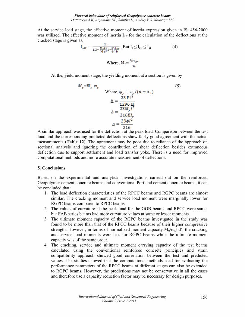
At the service load stage, the effective moment of inertia expression given in IS: 456-2000 was utilized. The effective moment of inertia Ieff for the calculation of the deflections at the cracked stage is given as,
; But Ir ≤ Ieff ≤ Igr (4)
Where, =
At the, yield moment stage, the yielding moment at a section is given by
= (5) Where,
A similar approach was used for the deflection at the peak load. Comparison between the test load and the corresponding predicted deflections show fairly good agreement with the actual measurements (Table 12). The agreement may be poor due to reliance of the approach on sectional analysis and ignoring the contribution of shear deflection besides extraneous deflection due to support settlement and load transfer yoke. There is a need for improved computational methods and more accurate measurement of deflections.
5. Conclusions
Based on the experimental and analytical investigations carried out on the reinforced Geopolymer cement concrete beams and conventional Portland cement concrete beams, it can be concluded that:
1. The load deflection characteristics of the RPCC beams and RGPC beams are almost similar. The cracking moment and service load moment were marginally lower for RGPC beams compared to RPCC beams.
2. The values of curvature at the peak load for the GGB beams and RPCC were same, but FAB series beams had more curvature values at same or lesser moments.
3. The ultimate moment capacity of the RGPC beams investigated in the study was found to be more than that of the RPCC beams because of their higher compressive strength. However, in terms of normalized moment capacity Mu/σcubd2, the cracking and service load moments were less for RGPC beams while the ultimate moment capacity was of the same order.
4. The cracking, service and ultimate moment carrying capacity of the test beams calculated using the conventional reinforced concrete principles and strain compatibility approach showed good correlation between the test and predicted values. The studies showed that the computational methods used for evaluating the performance parameters of the RPCC beams at different stages can also be extended to RGPC beams. However, the predictions may not be conservative in all the cases and therefore use a capacity reduction factor may be necessary for design purposes.
Flexural behaviour of reinforced Geopolymer concrete beams
Dattatreya J K, Rajamane NP, Sabitha D, Ambily P S, Nataraja MC
International Journal of Civil and Structural Engineering
Volume 2 Issue 1 2011 157
5. More extensive investigations are required to decide on the shape and parameters of the stress block and maximum compressive strain in concrete to provide more accurate prediction.
6. The measured deflections of beams compared with the predicted deflections calculated using the provisions of IS 456:2000 and conventional RC theory show fair agreement but call for improved prediction.
7. The crack patterns and failure modes observed for RGPC beams were found to be similar to the RPCC beams. The total number of the flexural cracks developed was almost same for all the beams. The beams failed initially by yielding of the tensile steel followed by the crushing of concrete in the compression face.
8. The crack widths, crack spacing and no. of cracks were comparable for both RPCC and RGPC beams.
Acknowledgement
This paper is being published with the kind permission of Director, CSIR-SERC, Chennai. The work was carried at the Advanced Materials Laboratory (AML) of CSIR- SERC, Chennai and the authors acknowledge the help and cooperation rendered by the Head, AML, staff, scientists, and project trainee students at AML.
6. References
1. Bakharev T. (2005a), Durability of geopolymer materials in sodium and magnesium sulfate solutions, Cement and Concrete Research, 35(6), pp 1233-1246.
2. Bakharev T., (2005), Geopolymeric materials prepared using Class Fly ash and elevated temperature curing, Cement and Concrete Research, 35, pp 1224-1232.
3. Bakharev T., (2005c), Resistance of geopolymer materials to acid attack, Cement and Concrete Research, 35(4), pp 658-670.
4. Bakharev T., Sanjayan J.G., Cheng J.B., (2003), Resistance of alkali-activated slag concrete to acid attack, Cement and Concrete Research, 33, pp 1607-1611.
5. Bakharev T., Sanjayan J.G., Cheng Y.B., (1999), Effect of elevated temperature curing on properties of alkali-activated slag concrete, Cement and Concrete Research, 29(10), pp 1619-1625.
6. Dattatreya J.K., Ambily P.S., Madheswaran C.K., Sabitha D., Neelamegam M. (2010), Experimental Studies on Shear Behaviour of Reinforced Geopolymer Concrete Beams, SERC Research Report No. RR-2, June.
7. Dattatreya J.K., Rajamane N.P., and Ambily P.S., (2009), Structural Behaviour of Reinforced Geopolymer Concrete Beams and Columns, SERC Research Report, RR-6, May.
8. Davidovits J. (1991), Geopolymers: inorganic polymeric new materials, Journal of Thermal Analysis, 37, pp 1633–1656.
Flexural behaviour of reinforced Geopolymer concrete beams
Dattatreya J K, Rajamane NP, Sabitha D, Ambily P S, Nataraja MC
International Journal of Civil and Structural Engineering
Volume 2 Issue 1 2011 158
9. Duxson P., Fernández-Jiménez A, Provis JL, Lukey GC, Palomo A, Van Deventer,(2007), Geopolymer technology, The current state of the art, Journal of Material Science , 42 (9),pp 2917–2933.
10. Fernández-Jiménez A., Palomo A., (2003), Characterisation of fly ashes, Potential reactivity as alkaline cements, Fuel, 82(18), pp 2259-2265.
11. Fernández-Jiménez A., Palomo A., López-Hambrados C.,(2006), Engineering Properties of Alkali-Activated Fly Ash Concrete, ACI Materials Journal 103(2), Mar–Apr, pp 106–112.
12. Hardjito D., and Rangan B.V., 2005, Development and properties of low calcium fly ash based geopolymer concrete, Research report GC-1, Curtin University of Technology, Perth, Australia.
13. Macgregor J.G. (1987). Reinforced Concrete Mechanics and Design, 3rd edition, Prentice Hall, New Jersey.
14. Palomo A., Fernández-Jiménez A., López-Hombrados C., Lleyda J.L.,2004, “Precast elements made of alkali activated fly ash concrete”, 8th CANMET/ACI International Conference on fly ash, silica fume, slag and natural pozzolans in concrete. Las Vegas, (U.S.A.), Supplementary Volume, pp 545-558
15. Palomo A., Grutzeck M.W.,Blanco M.T.,(1999), Alkali-activated Fly Ashes: A Cement for the Future, Cement and Concrete Research, 29, pp 1323–1329.
16. Phair J.W., 2006, Green chemistry for sustainable cement production and use, Green Chem., pp 763–780
17. Rajamane N.P., Dattatreya J.K., Ambily P.S., (2009), Bond Characteristics of Steel Rebars in Geopolymer Concrete, SERC Research Report, RR-7, May.
18. Rajamane N.P., P.S. Ambily, J.K. Dattatreya, D. Sabitha, (2010), Technical Feasibility Studies on Geopolymer Concrete Building Blocks / Pavers with Natural and Synthetic Aggregates, SERC Technical Report.
19. Rajamane N.P., P.S. Ambily, J.K. Dattatreya, D. Sabitha, C.K. Madheswaran, Neelamegam M., J. Annie Peter, (2009), Statistical Evaluation of Experimental Results, Internal Report RR-9, October.
20. Rajamane N.P., Sabitha D., (2005), “Studies on geo-polymer mortars using fly ash and blast furnace slag powder”, International Congress on Fly Ash, Fly Ash India, Chapter 6, pp 1-7.
21. Rajamane N.P., Sabitha D., and Sajana Mary James, (2005), Potential of industrial wastes to produce geo-polymeric mortar of practical utility - a study, Indian Concrete Institute Journal, Vol. 5, No 4, Jan-Mar, pp 9-20.
22. Rajamane N.P., Sabitha D., Sajana Mary James, Gopalakrishnan S.,(2005), “Studies on development of geo-polymeric low-energy cement from fly ash for structural applications”, Proceedings of the International Conference on Advances
Flexural behaviour of reinforced Geopolymer concrete beams
Dattatreya J K, Rajamane NP, Sabitha D, Ambily P S, Nataraja MC
International Journal of Civil and Structural Engineering
Volume 2 Issue 1 2011 159
in Concrete Composites and Structures, ICAS, 6-8 January, SERC, Chennai, India, pp 219-226.
23. Rangan B.V., (2006), Fly ash based geopolymer concrete, Research report GC-4, Curtin University of Technology, Perth, Australia.
24. Sofi D., Van Deventer J.S.J., Mendis P.A., Lukey G.C., (2006), Engineering properties of inorganic polymer concretes (IPCs), Cement and Concrete Research, 37, pp 251-257.
25. Sumajouw M.D.J., Rangan B.V., (2006), Low-Calcium fly ash based geopolymer concrete: Reinforced Beams and Columns, Research report GC-3, Curtin University of Technology, Perth, Australia.
26. Swanepoel J.C., Strydom C. A., (2002), Utilisation of fly ash in a geopolymeric material, Applied Geochemistry, 17(8), pp 1143-1148.
27. Van Jaarsveld J.G.S., van Deventer J.S.J., Lukey G.C., (2002a), The effect of composition and temperature on the properties of fly ash- and kaolinite-based geopolymers, Chemical Engineering Journal, 89(1-3), pp 63-73.
28. Van Jaarsveld, J.G.S., van Deventer J. S.J., Lukey G.C., (2003), The characterisation of source materials in fly ash-based geopolymers, Materials Letters, 57(7), pp 1272-1280.
29. Wallah S.E., Rangan B.V., (2006), Low-calcium fly ash based geopolymer concrete: long term properties. Research report GC-2, Curtin University of Technology,Perth, Australia