Embed Size (px)
Citation preview

155
4th International Conference on the Durability of Concrete Structures24–26 July 2014Purdue University, West Lafayette, IN, USA
Flexural Behavior of RC Beams Under Combined Effects of Acid–Salt Mist and Carbon Dioxide
Wu Yuan-Zhou, Lv Heng-Lin, and Fang Zhong-NianJiangsu Key Laboratory of Environmental Impact and Structural Safety in Engineering, School of Mechanics and Civil Engineering, China University of Mining and Technology
ABStRACt
The coupling effects of hydrochloric acid mist, carbon dioxide, and salt mist rich in Cl– and SO42– on the degradation
of reinforcement concrete (RC) beams were researched with the simulation of colliery ground environment (CGE) and experimental investigation. The results indicated that carbonation of concrete and corrosion of rebar increased slowly as the maximum width of crack became <0.5 mm. Meanwhile, the flexural carrying capacity of the deteriorated beam decreased slightly, while the concrete strength got a small increase first and a large decrease of more than 20% quickly. As the width of crack exceeded 0.5 mm, each target changed rapidly except the carbonation depth. Because of the interaction of deteriorated concrete and corroded rebar, the crack width, and flexural behavior of the beams have discrete correlation with the corrosion of rebar. The failure mode of beams changed from the crushing of compression concrete to the yielding of rebar.
Keywords: colliery ground environment, coupling effects of multi-factors, deterioration, flexural capacity, RC beams.
1. INtRoDUCtIoN
Reinforcement concrete (RC) structures serving in colliery ground environment (CGE) deteriorated and were damaged heavily under the coupling effect of load and corrosive mediums (Lv, Wu, & Zhou, 2014). According to the Chinese standard GB50046, the hydrogen chloride gas, chlorine gas, and the dust containing calcium and magnesium chloride on the surface caused serious deterioration of the concrete. The Cl– and SO4
2– contained in the water corroded the rebar and concrete, respectively. The hydrogen chloride gas and chlorine gas were considered as the major factors because of the severe and large-scale deterioration caused to the RC structures.
Each kind of corrosive medium led to the deterioration of the concrete and rebar, and to coupling. The acidic gases corroded the concrete and formed corrosion pitting on the surface of the concrete or even made it peel off, which facilitated the invasion of liquid. The mediums in the liquid corroded the concrete and rebar, producing cracks in the concrete, and conversely benefitted the gases. CaCl2 produced by the reaction dissolved in the water on the surface and led to further deterioration. Figure 1 indicated the deterioration of RC beams serving in the CGE.
Under the coupling effect of CGE, the concrete became loose or even cracked on the surface and the compressive strength decreased. The effective area and tensile stress of corroded rebar reduced, and the bond behavior between the deteriorated concrete and corroded rebar degraded. And then, the loaded area, carrying capacity,
and ductility of specimen reduced. The internal force was redistributed and the reliability of RC structures was affected because of the damage or crush of joint.
Figure 1. Deterioration of RC beams serving in CGE. (a) Cracks on the bottom of beam with 13 years service. (b) Exfoliation on the side of beam with 21 years service.

156 CoRRoSIoN
The deterioration of RC beams caused by mediums in the serving environment was paid great attention in recent years. A large quantity of results about the mechanical property of RC beams serving in atmosphere or marine environment were achieved by means of project measure, experimental investigation, or numerical calculation.
CaO in the concrete was eroded and the base balance between the minerals was destroyed when H+ contained in the acid rain deteriorated the concrete, and then C–S–H was dissolved, and the strength of materials decreased (Huiling, Ding, & Shaodong, 1997). CaSO4·2H2O or other more expansive crystals were produced as SO4
2– contained in the acid or salt water reacted with the concrete. The microcracks inside the concrete were expanded and the concrete cracked (Clark OBE, 2007; Niu, 2003). The Cl– invaded the concrete through the cracks easily, and then the electrochemical reaction occurred on the surface of rebar. The rust expanded the cracks and facilitated more corrosive medium, and then the deterioration continued with more serious expansion of the cracks and corrosion (Dang & Francois, 2013; Neville, 1995).
The bond performance between the deteriorated concrete and corroded rebar reduced for the reason that a layer of loose separator formed by the rust changed the interface and weakened the cementation significantly (García, Almeray, & Barrios, 2012; Ouglova, Berthaud, & Foct, 2008). Corrosion ratio played an important role in the cementation such that the ultimate strength and rigidity increased first and then reduced as the corrosion ratio increased. However, they were not less than the values of beams at the original stage when the ratio was not >5%. The slip of the free end reduced significantly with the increase of corrosion ratio when the cementation reached the ultimate value, 17.6% of the original at the corrosion ratio of 4.6%.
The concrete cracked and an effective area of section reduced as a result of concrete deterioration and rebar corrosion, and the flexural capacity of the RC beam decreased. The reduction of cementation between the concrete and rebar intensified the decrease. Some conclusions summarized from the research results (Azad, Ahmad, & Al-Gohi, 2009, 2010; Azad, Ahmad, & Azher, 2007; Ballim & Reid, 1997; Capozucca & Cerri, 2003; Niu, 2003) were indicated as follows: (1) The vertical splits of the deteriorated beam had a different development against the beam without deterioration under flexural load. They appeared relatively late and had a larger distance. (2) Longitudinal cracks appeared on the deteriorated beams and their rigidity was lower. (3) The ductility of the deteriorated beam decreased drastically and the fragility increased, and the plastic performance reduced obviously when the beam was destroyed.
The deterioration mechanism of RC beams serving in CGE differed from those of the research results, and then it has become necessary to do additional research. In CGE, the concrete deteriorated under the coupling effects of strong acids, weak acids, and sulfate, and the rebar was corroded by H+ and Cl– with chemical and electrochemical reaction, coexisting and interacting (Xiong, Cui, & Chen, 2004). The interaction led to the decrease in cementation and the beams cracked rapidly.
In this article, experimental investigation was undertaken expecting that the following objectives would be achieved: (1) to evaluate the deterioration of materials, including carbonation degree and compressive strength of concrete, and corrosion ratio of rebar; (2) to investigate the flexural behavior of deteriorated RC beams after each test cycle in terms of failure mode, flexural capacity, and rigidity; (3) to research the relationship between crack width or flexural capacity of beam and the corrosion ratio of rebar.
2. EXPERIMENtAL PRoGRAM
2.1 Beam specimens
The ordinary Portland cement 32.5 grade with the density of 3.18 g/cm3 and specific surface area of 350 m2/kg was used in this investigation. Crushed limestone with a maximum size of 16 mm and river sand with the fineness of 2.42 were used as coarse aggregate and fine aggregate, respectively. The mixture proportion is given in Table 1.
table 1. Mixture proportion used in the research.
w/c ratio
Mixture proportion (kg/m3) Compressive strength of 28 d (MPa)
Water Cement Fine aggregate
Coarse aggregate
0.56 192 343 576 1063 33.4
A total of eight beam specimens for seven cycles with the total length of 1500 mm were constructed and tested in flexure. The main test parameters were carbonation depth, compressive strength of concrete, and corrosion ratio of rebar, as well as crack width for corrosion expansion. The sectional dimensions of beam specimen and the typical cross-sections are shown in Figure 2.
Figure 2. Sectional dimensions of specimen and cross-section.

FLEXURAL BEhAvIoR oF RC BEAMS UNDER CoMBINED EFFECtS oF ACID–SALt MISt AND CARBoN DIoXIDE 157
2.2 Experimental methods
The major influence factors summarized from the data got from engineering measurement of CGE are gases HCl, Cl2 and CO2, liquid rich in Cl– and SO4
2–, calcium, and magnesium chloride. The HCl and Cl2 led to the deterioration of the concrete both by the means of producing hydrochloric acid when they dissolved in water and by the reaction with the calcium hydroxide, and then can be replaced by hydrochloric acid mist in the experimental investigation. Meanwhile, the corrosion of liquid can also be realized by spraying the salt mist containing NaCl, MgCl2, and Na2SO4 (Brown & Badger, 2000). The production containing calcium and magnesium chloride adhered on the surface of beam, and then the corrosion of them was realized. To keep the existence of acid–salt mixing mist, the temperature and humidity were taken at 50% and 75% RH, respectively. The details of the simulating environment were illustrated in Table 2.
A total of 3.5 months was taken as a test cycle, 3 months in the simulation environment and a half of month outside, according to the fact that about 2 months of weak deterioration in the actual project was because of low temperature or wind or rain.
All the beam specimens were made in January 2009 and placed in the laboratory for experimental investigation after a natural curing of 28 days. The beam specimens were placed in the simulation environment tighter since September 2009, and test was taken after each cycle. After the detection of appearance, especially the cracks, the beam was flexural loaded and concrete cores were taken from the bottoms of the beam for the detection of carbonation depth and compressive strength. And then, the steel bars were taken when the beam was broken for the detection of corrosion ratio and mechanical property. A total of eight beam specimens were utilized in this research, the beam L0 was taken as the comparison beam, which did not deteriorate. Beam L1–L7 deteriorated and beam L3 was not loaded after the detection of one and three cycles, respectively.
As shown in Figure 3, all specimens were simply supported and subjected to four-point bending. Each of the specimens had a clear span of 1200 mm and shear spans of 400 mm; therefore, bending was constant in the central zone with a length of 400 mm. The static load was applied by a hydraulic jack to the specimens through a steel spreader beam. The load was monotonically applied in two stages. The
first stage was load-controlled, in which the load was applied step–by-step at a rate of 10 kN per step until 75% of expected strength of the specimens, whereas the loading rate was 5 kN per step for their low load carrying capacity. The second stage was carried out in displacement-controlled mode and the loading increment was 1 mm per step. At the end of each increment, all the data were collected and cracks were sketched. The specimen was considered to have failed when its load carrying capacity dropped to 80% of its maximum measured load or developed a major physical deterioration.
To measure deflections of the beam specimens, the displacements at beam mid-span, loading points, and supports were monitored by transducers. The schematic arrangement of the transducers was included in Figure 3. Electrical resistance strain gages were also affixed on surfaces of beams before loading.
Electrical resistance strain gauges
Steel spreader beam
Rigid Support
Hydraulic jack
Beam Specimen
LVDT
Figure 3. Schematic of experimental setup and instrumentation (units: mm).
Displacement meters were installed at beam mid-span, loading points, and supports with the purpose of monitoring the deflections of the beams. Electrical resistance strain gauges were also affixed on surfaces of the beams, both two on the top and bottom and five on the side, as shown in Figure 3.
3. tESt RESULtS AND DISCUSSIoN
A summary of test results is indicated in Table 3. The neutralization depth, strength of concrete cylinder cored from side of the beam (fc
’), average corrosion rate of rebar (ηs), crack width caused by expansion of corroded rebar (ωs), ultimate loads (Nu), displacement
table 2. Details of simulation environment.
NaCl (by weight) MgCl2 (by weight) Na
2So
4 (by weight) Co
2 (by volume) hCl (mg/m3) temperature °(C) humidity (%)
0.25% 2.71% 10% 3300 ppm 128 50 75
158 CoRRoSIoN
ductility, and failure modes of beam specimens after each deterioration cycle are included in Table 3. The displacement ductility factor (μΔ) in this study is defined as the ratio of mid-span displacement at ultimate stage (Δu) and that at yield stage (Δy), where the former is obtained at 0.8Pp after reaching the peak load Pp, whereas the latter is obtained by linearly interpolating the displacement at 0.75Pp to the level of Pp (Park, 1989). Because the deterioration characteristic of beam specimens did not indicate obviously, the flexural behavior of deteriorated beams were tested at intervals of two cycles during the first four cycles, and then one cycle at interval.
3.1 General observations and failure modes
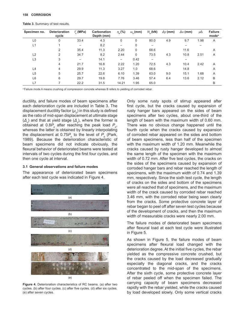
The appearance of deteriorated beam specimens after each test cycle was indicated in Figure 4.
(a)
(b)
(c)
(d)
(e)
Figure 4. Deterioration characteristics of RC beams. (a) after two cycles. (b) after four cycles. (c) after five cycles. (d) after six cycles. (e) after seven cycles.
Only some rusty spots of stirrup appeared after first cycle, but the cracks caused by expansion of rusty hanger bars appeared on the sides of beam specimens after two cycles, about one-third of the length of beam with the maximum width of 0.60 mm. There was no obvious change happened until the fourth cycle when the cracks caused by expansion of corroded rebar appeared on the sides and bottom of beam specimens, less than half of the specimen with the maximum width of 1.20 mm. Meanwhile the cracks caused by rusty hanger developed to almost the same length of the specimen with the maximum width of 0.72 mm. After five test cycles, the cracks on the sides of the specimens caused by expansion of corroded hanger bars and rebar reached the length of specimens, with the maximum width of 0.74 and 1.39 mm, respectively. Since the sixth test cycle, the length of cracks on the sides and bottom of the specimens were all reached that of specimens, and the maximum width of the crack caused by corroded rebar reached 3.46 mm, with the corroded rebar being seen clearly from the cracks. Some protective concrete layer of rebar began to peel off after seven test cycles because of the development of cracks, and then the maximum width of measurable cracks were nearly 2.00 mm.
The failure modes of deteriorated beam specimens after flexural load at each test cycle were illustrated in Figure 5.
As shown in Figure 5, the failure modes of beam specimens after flexural load changed with the deterioration degree. At the initial five cycles, the rebar yielded as the compressive concrete crushed, but the cracks caused by the load decreased gradually especially the diagonal cracks, and the cracks concentrated to the mid-span of the specimens. After the sixth cycle, some protective concrete layer of rebar peeled off when the specimen failed. The carrying capacity of beam specimens decreased rapidly with the rebar yielded, while the cracks caused by load developed slowly. Only some vertical cracks
table 3. Summary of test results.
Specimen no. Deterioration cycle
fc
’ (MPa) Carbonation Depth (mm)
ηs (%) ω
s (mm) N
u (kN) Δy (mm) Δu (mm) μΔ Failure
modea
L0 0 33.4 4.3 0 0 80.0 4.9 9.7 1.98 AL1 1 – 8.2 – 0 – – –
2 35.4 11.3 2.20 0 68.6 11.6 AL2 2 34.7 8.2 2.44 0 73.5 4.3 10.8 2.51 AL3 3 – 14.1 – 0.42 – –
4 21.7 16.8 2.22 1.20 72.5 4.3 10.4 2.42 AL4 4 29.9 11.3 3.27 1.0 68.6 14.8 AL5 5 25.7 22.6 6.10 1.39 63.0 9.0 15.1 1.68 AL6 6 29.7 19.8 7.76 3.46 57.4 6.4 13.6 2.12 BL7 7 22.2 31.5 14.21 1.95 65.0 B
a Failure mode A means crushing of compression concrete whereas B refers to yielding of corroded rebar.
FLEXURAL BEhAvIoR oF RC BEAMS UNDER CoMBINED EFFECtS oF ACID–SALt MISt AND CARBoN DIoXIDE 159
appeared in the mid-span of the beam specimen when it failed to bear load after seven cycles, which confirmed the failure mode of rebar yield vividly. The decrease of the bond performance between the deteriorated concrete and corroded rebar should be attributed to this phenomenon. The harmony of them was destroyed and the bond performance changed to between the well bonded and unbonded, thanks to the effect of stirrups and hanger bars (Wang & Liu, 2008).
(b)
(a)
(c)
(d)
(e)
Figure 5. Failure modes of deteriorated RC beams after flexural load. (a) after two cycles. (b) after four cycles. (c) after five cycles. (d) after six cycles. (e) after seven cycles.
3.2 Development of carbonation depth
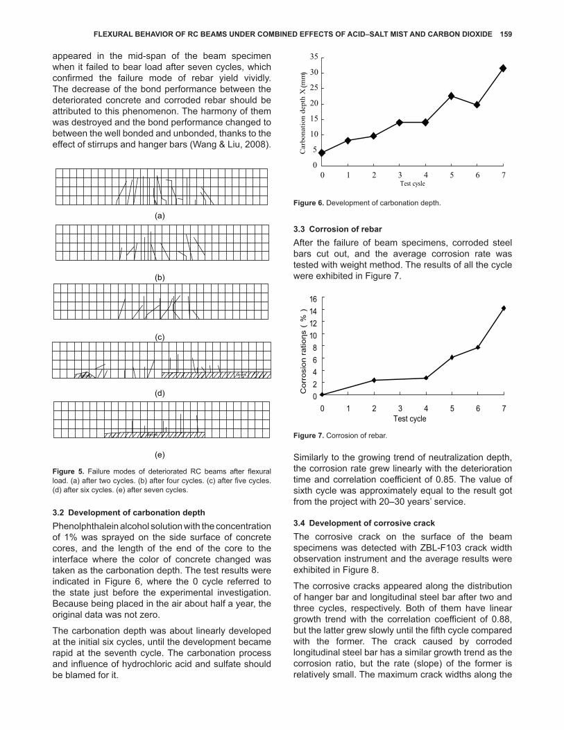
Phenolphthalein alcohol solution with the concentration of 1% was sprayed on the side surface of concrete cores, and the length of the end of the core to the interface where the color of concrete changed was taken as the carbonation depth. The test results were indicated in Figure 6, where the 0 cycle referred to the state just before the experimental investigation. Because being placed in the air about half a year, the original data was not zero.
The carbonation depth was about linearly developed at the initial six cycles, until the development became rapid at the seventh cycle. The carbonation process and influence of hydrochloric acid and sulfate should be blamed for it.
0
5
10
15
20
25
30
35
0 1 2 3 4 5 6 7Test cysle
Car
bona
tion
dept
h X
mm
Figure 6. Development of carbonation depth.
3.3 Corrosion of rebar
After the failure of beam specimens, corroded steel bars cut out, and the average corrosion rate was tested with weight method. The results of all the cycle were exhibited in Figure 7.
Figure 7. Corrosion of rebar.
Similarly to the growing trend of neutralization depth, the corrosion rate grew linearly with the deterioration time and correlation coefficient of 0.85. The value of sixth cycle was approximately equal to the result got from the project with 20–30 years’ service.
3.4 Development of corrosive crack
The corrosive crack on the surface of the beam specimens was detected with ZBL-F103 crack width observation instrument and the average results were exhibited in Figure 8.
The corrosive cracks appeared along the distribution of hanger bar and longitudinal steel bar after two and three cycles, respectively. Both of them have linear growth trend with the correlation coefficient of 0.88, but the latter grew slowly until the fifth cycle compared with the former. The crack caused by corroded longitudinal steel bar has a similar growth trend as the corrosion ratio, but the rate (slope) of the former is relatively small. The maximum crack widths along the

160 CoRRoSIoN
distribution of longitudinal steel bars on the corroded beam specimen after six deterioration cycles were close to the data got from the RC beams serving in the CGE for 20–30 years.
Figure 8. Development of corrosive cracks.
3.5 Relationship between crack width and corrosion ratio
As shown in Figure 9, the maximum width of the corrosive crack along the longitudinal steel bar was marked corresponding to the corrosion ratio.
Figure 9. Relationship between crack width and corrosion ratio.
Large discreteness existed between the crack width and corrosion ratio. Besides the inhomogeneity of concrete, three other factors influenced them, including the corrosion ratio of steel bars and deterioration degree of concrete and the cohesive action between them. With the increase of the corrosion ratio, the expansion crack grew. As the deteriorated concrete became loose, local pores inside the concrete were extruded by the corroded steel bars, slowing down the development of the crack until the corrosion ratio increased to higher degree. Meanwhile, the corrosion of steel bars and
deterioration of concrete caused the great decrease of cohesive action between them. After the crack width grew to a certain value, it would never increase again in spite of the growth of the corrosion ratio.
3.6 Degradation of the ultimate carrying capacity
The ultimate flexural carrying capacity of deteriorated beam specimens got from the bending test was exhibited in Figure 10.
Figure 10. Degradation of flexural capacity.
The degradation of flexural capacity of beam specimen indicates approximately linear trend with the correlation coefficient of 0.9377. Both the yield capacity and ultimate capacity decreased slowly at first and then rapidly as the growth of deterioration decreased. Only 10% was lost after four cycles, but the value exceeded 20% after a cycle later.
In each deterioration cycle, the curve of load-deflection was similar to the original, including three stages, as shown in Figure 11. The inflection points on the curve referred to the cracking load and yield load.
Figure 11. Curve of load–deflection.

FLEXURAL BEhAvIoR oF RC BEAMS UNDER CoMBINED EFFECtS oF ACID–SALt MISt AND CARBoN DIoXIDE 161
As the test cycle increased, the slope of the curves decreased, due to which the elastic modulus of the deteriorated beam specimens reduced against the increase of the deterioration time, which also explained the reason for the rigidity loss. On the other hand, the increase of crack width caused the decrease of effective area of the beam specimen, and then the carrying capacity decreased.
3.7 Effect of corrosion ratio to the ultimate carrying capacity
As shown in Figure 12, the relative flexural capacities of deteriorated beam specimens were marked corresponding to the corrosion ratio.
0.6
0.7
0.8
0.9
1
0 1 2 3 4 5 6 7
Corrosion ratio of rebar (%)
Rel
ativ
e fl
exur
al c
apac
ity
Figure 12. Relationship between flexural capacity and corrosion ratio.
The relationship between flexural capacity and corrosion ratio can be induced by the formulas shown in Equation (1):
�− +M /M = 0.0353 0.9674sus u0 (1)
where Mus and Mu0 are ultimate load borne by deteriorated and original beam specimens, respectively (unit: kN·m); ηs is the corrosion ratio. Because of the loss of sectional area caused by deterioration is ignored, the formula cannot be applied to calculate the ultimate carrying capacity with the data of actual sectional area of beam, corrosion ratio, and the cohesive action between the deteriorated concrete and corroded steel bars.
4. CoNCLUSIoNS
Gases, liquids, and solids contained in the CGIE degraded the flexural behavior of RC beams by means of physical, chemical, and mechanical effects. The coupling effect caused the deterioration of the concrete and corrosion of steel bars and the cohesive action between them was also weakened. The experimental investigation results coincide with the data from the projects, confirming that the effects of multi-factors exceeded the single factor much more.
Based on the results of this investigation, the following conclusions can be drawn:
(a) With the increase in deterioration, the failure mode changed from the plastic collapse to brittle fracture because of the crushing of compression concrete attributed to the loss of cohesive action between hanger bars and compressive concrete.
(b) The neutralization depth of concrete, corrosion ratio, and tensile strength of steel bars, even the crack width and relative ultimate carrying capacity of the beam specimens all indicated linear growth trend.
(c) The crack width and the flexural capacity of beam specimen are both influenced linearly by the corrosion ratio of steel bars, but the results differ from the electric corrosion when deterioration of concrete was ignored.
(d) Besides the cohesive action, the degree of deterioration of concrete and corrosion ratio of steel bars interacted and worsened the results.
(e) The results got from the experimental investigation of six cycles are close to the data got from the projects with 20–30 years’ service, confirming the accuracy of the experiment and possibility of the application to the projects.
ACKNoWLEDGMENtS
This study was supported by the Natural Science Foundation of Jiangsu Province (BK2008128), the Open Foundation of Jiangsu Key Laboratory of Environmental Impact and Structural Safety in Engineering (JSKL2011ZD02), and a project funded by the Priority Academic Program Development of Jiangsu Higher Education Institutions. The authors would like to express their sincere appreciation of the support. The experimental work described in this article was conducted at the Jiangsu Key Laboratory of Environmental impact and Structural Safety in Civil Engineering in the China University of Mining and Technology. The authors would like to acknowledge staffs and students and all those who helped during the testing at the laboratory.
REFERENCES
Azad, A. K., Ahmad, S., & Al-Gohi, B. H. A. (2009). Flexural strength of corroded reinforced concrete beams. China Civil Engineering Journal, 42(11), 64–70.
Azad, A. K., Ahmad, S., & Al-Gohi, B. H. A. (2010). Flexural strength of corroded reinforced concrete beams. Magazine of Concrete Research, 62(6), 405–414.
Azad, A. K., Ahmad, S., & Azher, S. A. (2007). Residual strength of corrosion-damaged reinforced

162 CoRRoSIoN
concrete beams. ACI Materials Journal, 104(1), 40–47.
Ballim, Y., & Reid, J. C. (1997). Reinforcement corrosion and the deflection of RC beams-An experimental critique of current test methods. Cement and Concrete Composites, 19(2), 131–137.
Brown, P. W., & Badger, S. (2000). The distributions of bound sulfates and chlorides in concrete subjected to mixed NaCl, MgSO4, Na2SO4 attack. Cement and Concrete Research, 30(10), 1535–1542.
Capozucca, R., & Cerri, M. N. (2003). Influence of reinforcement corrosion-in the compressive zone-on the behavior of RC beams. Engineering Structures, 25(13), 1575–1583.
Clark OBE, L. A. (2007). The management of the thaumasite form of sulphate attack in the UK. Magazine of Concrete Research, 59(7), 465–467.
Dang, V. H., & Francois, R. (2013). Influence of long-term corrosion in chloride environment on mechanical behavior of RC beams. Engineering Structures, 48, 558–568.
Fang, C., Lundgren, K., Chen, L., & Zhu, C. (2004). Corrosion influence on bond in reinforced concrete. Cement and Concrete Research, 34(11), 2159–2167.
García, J., Almeraya, F., Barrios, C., Gaona, C., Núñez, R., López, I., ... Bastidas, J. M. (2012). Effect of cathodic protection on steel–concrete bond strength using ion migration measurements. Cement and Concrete Composites, 34(2), 242–247.
Huiling, L., Ding, Z., & Shaodong, X. (1997). A study on influences of acid rain in southwest China on concrete. Journal of Harbin Institute of Technology, 29(16), 101–104.
Lv, H.-L., Wu, Y.-Z., & Zhou, S.-C. (2014). Damage and deterioration mechanism and control technique of reinforced concrete structures serving in colliery ground industrial environment [M]. Xuzhou, China: China University of Mining and Technology Press.
Neville, A. (1995). Chloride attack of reinforced concrete: An overview. Materials and Structures, 28, 63–70.
Niu, D. (2003). Durability and life forecast of reinforced concrete structures [M]. Beijing, China: Science Press.
Ouglova, A., Berthaud, Y., Foct, F., François, M., Ragueneau, F., & Petre-Lazar, I. (2008). The influence of corrosion on bond properties between concrete and reinforcement in concrete structures. Materials and Structures, 41(5), 969–980.
Park, R. (1989). Evaluation of ductility of structures and structural sub-assemblages from laboratory testing. Bulletin of the New Zealand National Society for Earthquake Engineering, 22(3), 155–166.
Wang, X.-H., & Liu, X.-L. (2008). Modeling the flexural carrying capacity of corroded RC beams. Journal of Shanghai Jiaotong University (Science), 13(2), 129–135.
Xiong, G., Cui, Y., Chen, L., & Jiang, H. (2004). Influence of hydrochloric acid etching on bond strength between concrete substrate and repair materials. Cement and Concrete Composites, 26, 41–45.
Yang, H., Jiang, L., Zhang, Y., & Pu, Q (2013). Flexural strength of cement paste beam under chemical degradation: Experiments and simplified modeling. Journal of Materials in Civil Engineering, 25, 555–562.