Embed Size (px)
Citation preview

COMPUTER METHODS IN APPLIED MECHANICS AND ENGINEERING 66 (1988) 173-198 NORTH-HOLLAND
FLEXURAL ANALYSIS OF LAMINATED COMPOSITES USING REFINED HIGHER-ORDER C ° PLATE BENDING ELEMENTS
B.N. PANDYA and Tarun KANT Department of Civil Engineering, Indian Institute of Technology, llT-Powai, Bombay 400 076, India
Received 15 October 1986
A finite element formulation for flexure of a symmetrically laminated plate based on a higher-order displacement model and a three-dimensional state of stress and strain is presented here. The present higher-order theory incorporates linear variation of transverse normal strains and parabolic variation of transverse shear strains through the plate thickness, and as a result it does not require shear correction coefficients. A nine-noded Lagrangian parabolic isoparametric plate bending element is described. The applications of the element to bending of laminated plates with various loading, boundary conditions, and lamination types are discussed. The numerical evaluations also include the convergence study of the element used. The present solutions for deflections and stresses are compared with those obtained using the three-dimensional elasticity theory, closed-form solutions with another high-order shear deformation theory, and the Mindlin's theory. In addition, numerical results for a number of new problems, not available in the literature, are presented for future reference.
1. Introduction
Multilayered composites are important structural materials in weight sensitive aerospace applications, where high strength-to-weight and stiffness-to-weight ratios are desired. Such composites, idealized as orthotropic lamina, are bonded together to form a laminate and are used as structural components. The finite element formulation provides a convenient method of solution for such laminated composites having complex geometry and arbitrary loading as well as support conditions.
Analysis of such a laminate in the past has been based on one of the following two types of plate theories: • The classical lcmination theory based on Kirchhoff hypothesis. • First-order shear def~:~mation theories. In both theories it is assumed that the laminate is in a state of plane stress. The classical lamination theory [1, 2], which is an extension of the classical thin plate theory [3, 4] to laminated plates, neglects the effects due to transverse shears and normal strain in the thickness direction. It was soon realised that these effects are more significant for laminated composite plates than for isotropic plates due to high ratio of in-plane modulus to transverse shear modulus. Further, it was also observed that the classical thin plate theory based on the so-called Kirchhoff hypothesis is computationany inefficient (C 1 continuous) from the point of view of simple finite element formulations [5, 6]. The errors in such a theory naturally increase as the plate aspect ratio (a/h < 10) decreases. For instance, in plates with aspect ratio less than
0045-7825188153.50 © 1988, Elsevier Science Publishers B.V. (North-Holland)

174 B.N. Pandya, T. Kant, Flexural analysis of laminated composites
ten and high degree of orthotropy, Ashton and Whitney [7] have reported enormous discrepancy in the results of the classical thin plate theory.
The shear deformation theories which include transverse shear deformation can be classified on the basis of the assumed fields as (i) stress-based theories and (ii) displacement-based theories. Reissner [8] and Mindlin [9] are the two pioneers to provide first-order shear deformable theories based on the assumed stresses and displacements variation through the thickness of the plate, respectively. Medwadowski [10] has extended Reissner's theory to orthotropic plates. Yang, Norris and Stavsky [11], on the other hand, have extended Mindlin's theory to heterogeneous plates.
The foregoing theories provide a first-order basis for the consideration of the transverse shear deformations effect on the behaviour of isotropic, orthotropic, and heterogeneous plates and these also yield a C o continuous finite element formulation for the numerical analysis but have certain limitations: • The transverse shearing strains/stresses are assumed constant through the plate thickness
and a fictitious shear correction coefficient is introduced. • The nonzero transverse shear stresses on the bounding planes of the plate are contradictory
to the basic requirements for the equilibrium. • The classical contradiction whereby the plates are assumed to be in a state of plane
stress/strain remains unresolved. Reissner [12] and Lo, Christensen and Wu [13, 14] have presented a theory for plates based on assumed higher-order displacement field. Kant [15] has derived an isotropic version of the complete governing equation of such a theory based on the minimum potential energy principle and has also compared it with Mindlin theory through extensive numerical studies. A C o finite element formulation of this higher-order theory is presented by Kant, Owen and Zienkiewicz [16]. In this theory, the in-plane and the transverse displacements are expanded in the powers of the thickness coordinate (z) by Taylor series and the truncations are effected at the third and the second degrees, respectively. The theory thus incorporates: • Quadratic variation of the transverse shearing strains (3~xz and Tyz) through the plate
thickness, avoiding the introduction of a shear correction factor. • Linear variation of the transverse normal strain (ez) through the plate thickness • Consideration of the complete three-dimensional Hooke's law. Pandya and Kant [17] have extended this theory for generally orthotropic plates. The present work is a further development of this theory for flexure of symmetrically laminated anisotropic composite plates.
Recently, Bert [18] has presented an evaluation of various plate theories developed for laminated composites. Phan and Reddy [19] have presented a finite element formulation of a plate theory based on an assumed displacement field of Levinson [20] and Murthy [21] in w'lich in-plane displacements are expanded as cubic functions of the thickness coordinate while the transverse deflection is kept only a function of x and y as assumed in the classical shear deformation theories. Hence, implicit in this development is the use of only a partial constitutive relation which ignores the contributions and effects of transverse normal stress (cr~)/strain (e~). The higher-order functions used in the definition of the in-plane displace- ments are eliminated and expressed in terms of the usual physical lower-order displacement functions of the classical shear deformable theories by conditioning that the transverse shear stresses are zero on the bounding planes of the plates. The resulting formulation is seen to
B.N. Pandya, T. Kant, Flexural analysis of laminated composites 175
contain second-order derivatives of the transverse deflection (w) in the energy expression and consequently the displacement-based finite element formulation requires the use of computa- tionally inefficient C t continuous shape functions. Further, for laminated composite plates, the evaluation of transverse shear stresses from the constitutive relations is not justified technically as it violates the continuity of transverse shear stresses at the interfaces. In addition, it is noted that for the laminated composite plates, the feasible and accurate prediction of transverse shear stresses are cumbersome [22] and can only be obtained from the stress equilibrium equations which satisfy both the requirements of zero transverse shear stresses on the bounding planes of the plate as well as transverse shear stress continuity at the interfaces.
An extremely important aspect in the design and manufacture of the fibre-reinforced laminates is the prediction of its failure mode(s) under the given set of load conditions. The delamination mode of the failure is now recognized as the most critical one [23]. This type of failure mode is due to interlaminar stresses 7xz, ~-yz, and also or~, which is not considered by Reddy [19], Levinson [20], and Murthy [21]. We believe the present formulation has the potential to predict all the six components of stresses and displacement components accurate- ly. In order to demonstrate the accuracy and efficiency of the present finite element technique, solutions of problems for which analytical solutions [22, 24] are available are selected so that a comparison between the analytical and numerical solutions could be made. In addition, numerical results are presented for various other boundary conditions and loading cases, some of which may serve as bench marks for future investigators.
2. A higher-order theory for composite laminates
The development of the present theory starts with the assumption of the displacement field in the following form:
3 * V(x, y, z )= zOo(x, y ) + z o~ (x, y) ,
3 * V(x, y, z)= zo,(x, y)+ z 'o, (x, y), (1)
W(x, y, z)= w(x, y)+ z%*(x, y),
in which the various terms have the usual meaning except the terms 0 x , O r , and w* which are the corresponding higher-order terms in the Taylor-series expansion and are defined at the reference plane in the present theory [15, 16].
By substitution of these relations into the strain-displacement equations of the classical theory of elasticity [1] the following relationships are obtained:
,~,, = zK, + z~tC * ,
3 * 7~r = z K x y + z K,,y '
3 ey = z K y + z K y ,
2 * yyz = % + z g' r ,
e,~ = z K z ,
2 * 7x~= ~,, + Z tpx
(2)
in which
[K., K,, K J ' = [oOJOx, aO~lOy, oo~loy + oo~loxl' ,
176 B.N. Pandya, T. Kant, Flexural analysis of laminated composites
, =[OOx/OX, * * [r*~,r,,rx, rA' OOy/Oy, OO*/Oy+OOy/Ox, 2w*l'
[¢x, ¢,r = [ow/Ox + ox, ow/oy + o,1', (2a)
[cp* = , ¢~1' [aw* /ax + 30", a w * / a y + 30;1 t
The stress-strain relationship for the lth layer (lamina) of the composite laminate has the following form:
'trx' Qll Q12 Q13 Q14 0 0 try Q12 Q22 Q23 Q24 0 0 °rz ,= Q13 Q23 Q33 Q34 0 0
' Txy : Q14 Q24 Q34 Q44 0 0 'ry z 0 0 0 0 Q55 Q56
,'rxz , 0 0 0 0 Q56 Q66
'e x ey
£z %j, ~z
, 'Yxz
(3)
This may be w~ten in a compact form as
tr = Q e , (3a)
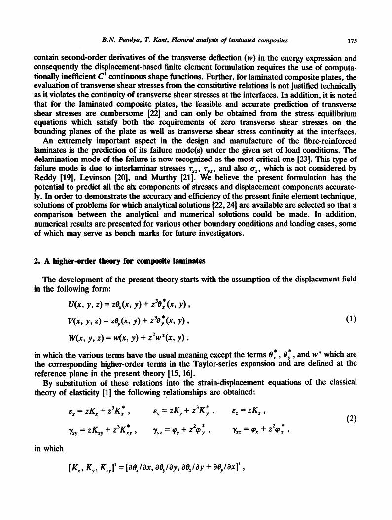
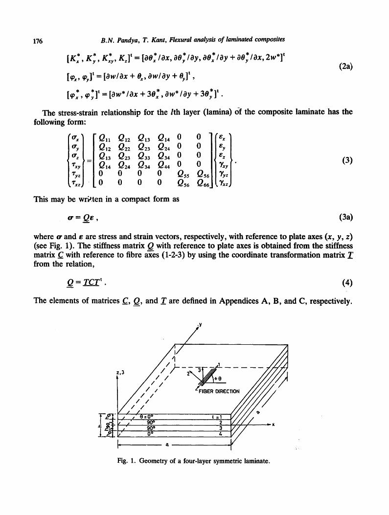
where cr and e are stress and strain vectors, respectively, with reference to plate axes (x, y, z) (see Fig. 1). The stiffness matrix Q with reference to plate axes is obtained from the stiffness matrix C with reference to fibre axes (1-2-3) by using the coordinate transformation matrix 7_' from the relation,
Q = T C T t . (4)
The elements of matrices _C, Q, and _T are defined in Appendices A, B, and C, respectively.
' ° : ' : : g / / / - _ .
V a =1
Fig. 1. Geometry of a four-layer symmetric laminate.

B.N. Pandya, T. Kant, Flexural analysis of laminated composites 177
Integration through thickness of (3) with strain terms given by (2) gives the plate constitutive relations. The constitutive relations involving bending moments are given by
M = DbK, (5)
in which
* =~ * )t M = (M,, My, Mx,, M x , M,, M,,, M, ,
K---- (Kx, Uy, Kxy , K'x, Ky , fxy , Kz) t
___Db= i--1
"QIIHI QI2H1 QI4HI QIIH2 Q22H1 Q24H1 Q12H2
Q44H1 Q,4H2 Q,,H3
Symmetric
Q,2H2 Q,4H2 Q13H7 Q22H2 Q24H2 Q23H1 Q24H2 Q44H2 Q34H1 Q12/-/3 QI4H3 Q,3H2 Q22H3 Q24H3 Q23H2
Q44H3 Q34H2 Q~H~_
lth layer
(5a)
where
n = No. of layers in a laminate,
H, ~(h 3 - 3 1 5 5 = = -- h /+ l ) h i+ l ) , H2 ~(hl H3 ~(h 7_ 7 = h i+ l ) .
(5b)
The elements of the moment vector M are defined as follows:
I Sh[lh' - My , - - My * ~ % [z, z3ldz , ' = ' , + , %J M~y M~y
M z = ¢rzZ dz . /=1 !+1
(5c)
(5d)
The constitutive relations involving shear forces are given by
Q =~,;, , (6)
where
* *)t ¢, = (~x, ~ , , ,px, ,Py ,
Q66H Qs6 H Q6~.,HI Qs6HI1 '8,°'
Q,,H
l=l Symmetric QssH2J
(6a)

178
in which H = (ht vector Q are defined as follows:
B.N. Pandya, T. Kant, Flexural analysis of laminated composites
- h~+l) and H 1, H 2 are already defined. The components of the shear force
Q, Q~ ,=1 ,+, "ryz [1, z 2]dz . (6b)
3. Finite element discretization
We follow the standard finite element discretization procedure in which the total solution domain/] is subdivided into 'ME' subdomains (e lements ) /~1 , /~2 , . . . , OME such that
ME H(d) = Z l i e ( d ) , (7)
e=l
where H and H e are the total potential of the system and the element, respectively. We further express
He(d)-- U e - W e , ( 8 )
in which U e and W e are the internal strain energy and the external work done expressions, respectively, and d is the vector of dependent displacement variables in the problem and is defined in the present case as:
* *) t a = ( w , w*, . (9)
In the C O finite element theory the continuum displacement vector within the element is discretized such that
NE
d= ~ Ni(x, y)d,, (10) i---I
in which the term N~(x, y) is the interpolating (shape or basis) function associated with node i, d~ is the value of d corresponding to node i, and 'NE' is the number of nodes in the element. Equation (10) ensures that the approximate d is not only continuous within the element but over the entire domain since the same value of d is used for all the elements at the common nodes. Thus C o formulation makes the relation (7) a true one.
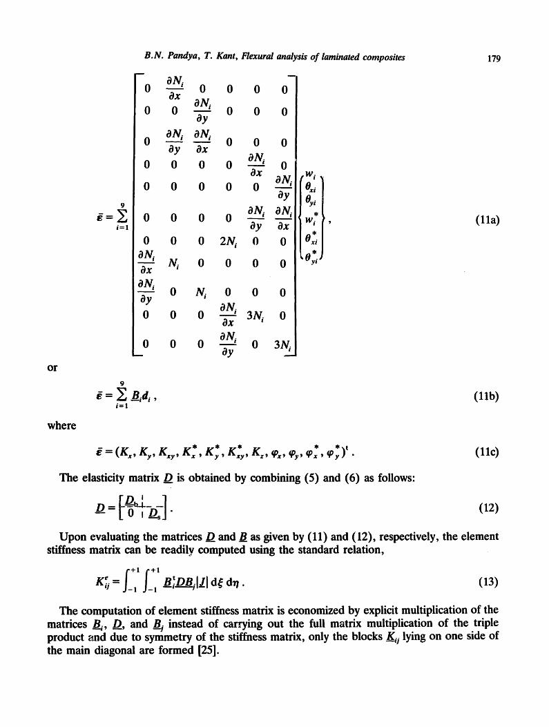
In the present analyses, the nine-noded quadrilateral from the Lagrangian family of two-dimensional C O continuous isoparametric elements with six degrees of freedom per node as per (9) is developed. With the generalized displacement vector d known at all points within the element as per (10), the generalized strain vector ~ at any point is expressed as follows:
B.N. Pandya, T. Kant, Flexural analysis of laminated composites 179
i = 1
m
0
0
0
ON, o o 8x 0 ON, 0
8y
ON i ON, 0 8y 3x
0 0 0 0 ~TO,,i 3x
0 0 0 0 0
o
o
o
o o o ON, ay
0
aN, Oy
ON, Ox
0
0
0 0 0 2N, 0 ON, -5-; IV, 0 0 0
ON, ay 0 N, 0 0 0
0 0 0 ON, ax 3Ni 0
oN, _0 0 0 8y 0 3N,_.
eWi ,
0~, o,,
* Wi
Ox* *
b Oyi ~
', (11a)
o r
~= E B,d~, (11b) i = 1
where
* * * * * ) t ~ = ( K . , ICy, K . , K . , K , , K . , K., ,~, ~ , , , , ,~ . (llc)
The elasticity matrix D is obtained by combining (5) and (6) as follows:
[___D_~_ ._] (12) ---D = L o ~ D_sJ"
Upon evaluating the matrices D and _B as given by (11) and (12), respectively, the element stiffness matrix can be readily computed using the standard relation,
l?f? K~ = _ _ B__JDBjIJJ d~ d~ . (13)
The computation of element stiffness matrix is economized by explicit multiplication of the matrices B i, D, and _Bj instead of carrying out the full matrix multiplication of the triple product and due to symmetry of the stiffness matrix, only the blocks ~ j lying on one side of the main diagonal are formed [25].
180 B.N. Pandya, T. Kant, Flexural analysis of laminated composites
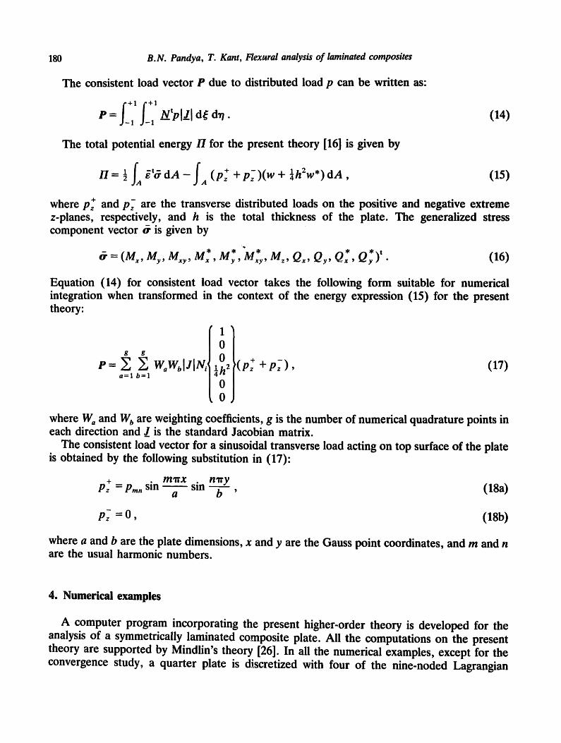
The consistent load vector P due to distributed load p can be written as:
P = _ _ u ' p l ! l d~ d•. ( 1 4 )
The total potential ene rgy / / fo r the present theory [16] is given by
H= ½ f~ g:'OdA- f (p+~ +p-~)(w+ ~h:w*)dA A (15)
where p f and p f are the transverse distributed loads on the positive and negative extreme z-planes, respectively, and h is the total thickness of the plate. The generalized stress component vector & is given by
* * " * * ) t ffr = ( Mx, My, Mxy, Mx , My , Mxy, M~, Q~, Qy, Q*, Qy . (16)
Equation (14) for consistent load vector takes the following form suitable for numerical integration when transformed in the context of the energy expression (15) for the present theory:
' 1 '
0 g g 0 ( + P - E Z wow~lJIN,' ~h ~ pz +p-~), ( 1 7 )
a=l b = l 0
~ 0 ,
where W a and W b are weighting coefficients, g is the number of numerical quadrature points in each direction and J_ is the standard Jacobian matrix.
The consistent load vector for a sinusoidal transverse load acting on top surface of the plate is obtained by the following substitution in (17):
+ mxtx n~ry Pz = Pmn sin ~ sin ~ (18a) a b '
p~- = 0 , (18b)
where a and b are the plate dimensions, x and y are the Gauss point coordinates, and m and n are the usual harmonic numbers.
4. Numerica l examples
A computer program incorporating the present higher-order theory is developed for the analysis of a symmetrically laminated composite plate. All the computations on the present theory are supported by Mindlin's theory [26]. In all the numerical examples, except for the convergence study, a quarter plate is discretized with four of the nine-noded Lagrangian
B.N. Pandya, T. Kant, Flexural analysis of laminated composites 181
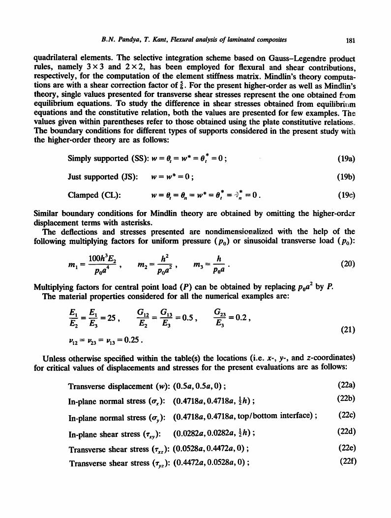
quadrilateral elements. The selective integration scheme based on Gauss-Legendre product rules, namely 3 x 3 and 2 x 2, has been employed for flexural and shear contributions, respectively, for the computation of the element stiffness matrix. Mindlin's theory computa- tions are with a shear correction factor of 5. For the present higher-order as well as Mindlin's theory, single values presented for transverse shear stresses represent the one obtained from equilibrium equations. To study the difference in shear stresses obtained from equiiibri:~m equations and the constitutive relation, both the values are presented for few examples. The values given within parentheses refer to those obtained using the plate constitutive relations,,. The boundary conditions for different types of supports considered in the present study wit~l the higher-order theory are as follows:
Simply supported (SS): w = 0 t = w * = Of = 0 ; (19a)
Just supported (JS): w = w* = O; (19b)
* ~* Clamped (CL): w = 0 t = On = w* = 0 t = ,, n = 0. (19c)
Similar boundary conditions for Mindlin theory are obtained by omitting the higher-order displacement terms with asterisks.
The deflections and stresses presented are nondimension~d~ed with the help of the following multiplying factors for uniform pressure (P0) or sinusoidal transverse load (P0):
100h3E2 h 2 h m 1 = m 2 - m 3 = . ( 2 0 )
po a4 ' po a2 ' po a
Multiplying factors for central point load (P) can be obtained by replacing po a2 by P. The material properties considered for all the numerical examples are:
__=m=El E1 2 5 , G12 - GI3 - 0 . 5 , G23 -- 0 . 2 ,
E2 E3 E 2 E 3 E 3
VI2--'~ //23 ~-- V13--'~ 0 . 2 5 .
(21)
Unless otherwise specified within the table(s) the locations (i.e. x-, y-, and z-coordinates) for critical values of displacements and stresses for the present evaluations are as follows:
Transverse displacement (w): (0.5a, 0.5a, 0) ;
In-plane normal stress (or x):
In-plane normal stress (or y):
In-plane shear stress 0"xy):
(0.4718a, 0.4718a, ½h) ;
(0.4718a, 0.4718a, top/bottom interface) ;
(0.0282a, 0.0282a, ½h) ;
Transverse shear stress (~xz): (0.0528a, 0.4472a, 0) ;
Transverse shear stress 0"yz): (0.4472a, 0.0528a, 0) ;
(22a) (22b)
(220
(220)
(22e) (22f)

182 B.N. Pandya, T. Kant, Flexural analysis of laminated composites
The locations for critical values of stresses for elasticity and closed-form solutions presented for comparisons are at the nearest nodal points.
The various examples considered are as follows.
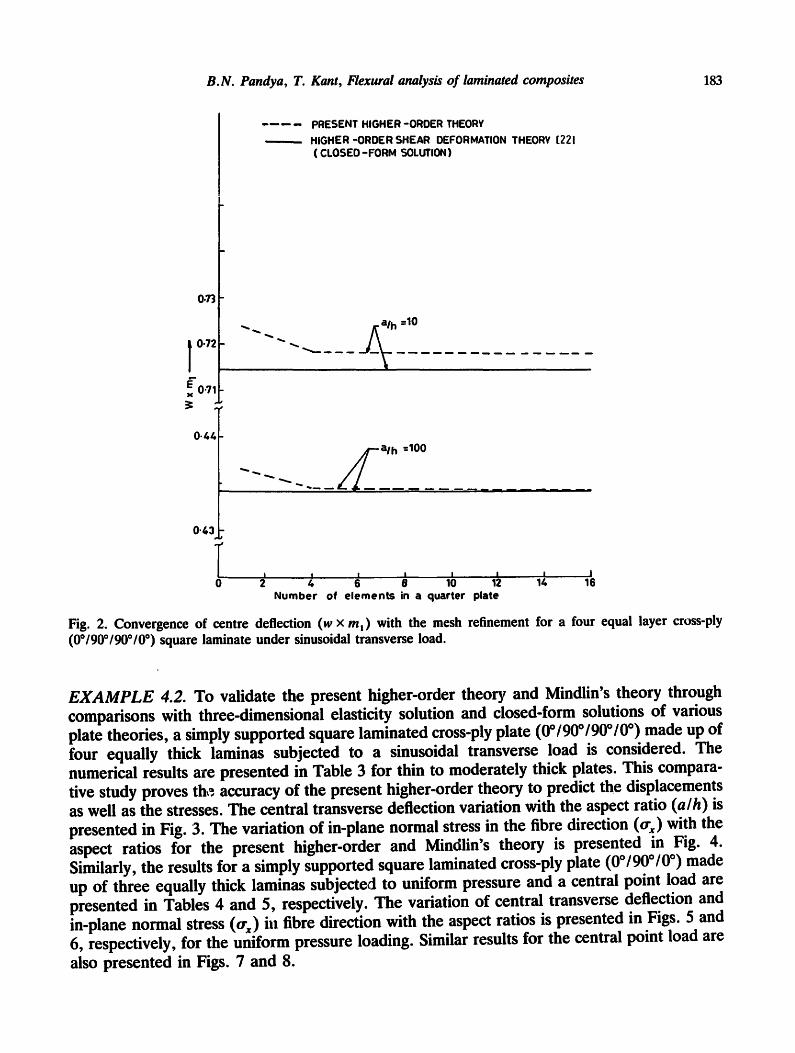
EXAMPLE 4.1. A simply supported square laminated cross-ply plate (0°/90°/90°/0°) made up of four equally thick laminas subjected to a sinusoidal transverse load is considered for convergence study. The numerical results are presented and compared in Tables 1 and 2 for side-to-thickness ratios (a/h) of 10 and 100, respectively. The convergence of centre deflec- tions is shown graphically in Fig. 2. It is clear from this figure that the 2 x 2 mesh in a quarter plate gives sufficiently accurate prediction of displacements and hence the stresses. It is advised to use refined mesh for better transverse shear stress predictions.
Table 1 Convergence of deflections and stresses in a simply supported four layer cross-ply (0°/90°/90°/0°) square laminate under sinusoidal transverse load (hi = -~h, i = 1 , . . . , 4 and a/h = 10)
Source
Present higher-order theory
Higher-order shear deformation theory [22]
Mesh size in quarter
plate
l x l
2 x 2
3 1 3
4 x 4
w x ml tr# X m 2 try X m 2 l"#y X m 2 l-xz X m 3 ,ry z X m 3
(0.2473) (0.1405) 0.72402 0.5701 0.3944 0.02705 0.1862 0.1159
(0.2756) (0.1552) 0.7185 0.5676 0.3948 0.02728 0.2702 0.1715
(O.28O3) (0.1578) 0.71809 0.5635 0.3924 0.02725 0.2887 0.1834
(0.2818) (0.1587) 0.71801 0.5619 0.3914 0.02723 0.2956 0.1877
0.7147 0.5456 0.3888 0.02680 0.2640 0.1531
3D elasticity [24] - 0.7370 0.5590 0.4010 0.02750 0.3010 0.1960
Table 2 Convergence of deflections and stresses in a simply supported four layer cross-ply (001900190010 °) square laminate under sinusoidal transverse load (hi = }h, i = 1 , . . . , 4 and a/h = 100)
Source
Present higher-order theory
Higher-order shear deformation theory [22]
Mesh size in quarter
plate
l x l
2 x 2
3 x 3
4 1 4
w x m ! trxxm2 t ryxm 2 ~'xyxm 2 ~'xzxm 3 ~-yzxm 3
(0.2710) (0.09922) 0.43659 0.5411 0.2718 0.02148 0.2045 0.08562
(0.3046) 0.4346 0.5442 0.2734 0.02154 0.3024 0.1240
(0.1114) (0.3109) (0.1136)
0.43443 0.5418 0.2723 0.02144 0.3216 0.1321
(0.3130) (0.1144) 0.43439 0.5406 0.2717 0.02140 O.3288 0.1350
0.4343 0.5387 0.2708 0.02130 0.2897 0.1117
3D elasticity [24] - 0.4347 0.5390 0.2710 0.02140 0.3390 0.1390
B.N. Pandya, T. Kant, Flexural analysis of laminated composites 183
0.73
0.72
E 0.71 X
. . . . PRESENT HIGHER-ORDER THEORY , _ HIGHER-ORDER SHEAR DEFORMATION THEORY [221
( CLOSED -FORM SOLUTION)
~ ~ --. / ~a /h =10
0"44 I ~ " ~ ~ "- -.-- __ j a l h --100
0"43~
Number of elements in a quarter plate
I 16
Fig. 2. Convergence of centre deflection (w x m~) with the mesh refinement for a four equal layer cross-ply (0o/90o/90o/0 °) square laminate under sinusoidal transverse load.
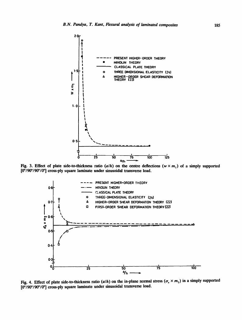
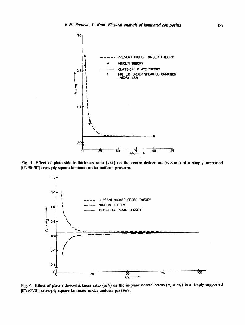
EXAMPLE 4.2. To validate the present higher-order theory and Mindlin's theory through comparisons with three-dimensional elasticity solution and closed-form solutions of various plate theories, a simply supported square laminated cross-ply plate (0 °/90 °/90 °/0 °) made up of four equally thick laminas subjected to a sinusoidal transverse load is considered. The numerical results are presented in Table 3 for thin to moderately thick plates. This compara- tive study proves the accuracy of the present higher-order theory to predict the displacements as well as the stresses. The central transverse deflection variation with the aspect ratio (a/h) is presented in Fig. 3. The variation of in-plane normal stress in the fibre direction (or x) with the aspect ratios for the present higher-order and Mindlin's theory is presented in Fig. 4. Similarly, the results for a simply supported square laminated cross-ply plate (0°/900/0 °) made up of three equally thick laminas subjected to uniform pressure and a central point load are presented in Tables 4 and 5, respectively. The variation of central transverse deflection and in-plane normal stress (or) in fibre direction with the aspect ratios is presented in Figs. 5 and 6, respectively, for the uniform pressure loading. Similar results for the central point load are also presented in Figs. 7 and 8.

184 B.N. Pandya, T. Kant, Flexural analysis of laminated composites
Table 3 Deflections and stresses in a simply supported four layer cross-ply (00/900190010 °) square laminate under sinusoidal transverse load (h~ = ~h, i = 1 , . . . , 4)
Source a / h
Present higher-order theory 4
Mindlin theory
3D elasticity [24] Higher-order shear deformation theory [22] First-order shear deformation theory [22]
Present higher-order theory
w x m~ ~x X m 2 ~y X m 2 fxy X m 2 7xz X m 3 ~y= X m 3
(0.2062) (0.2393) 1.8744 0.7163 0.6250 0.04537 0.2023 0.2610
(0.1132) (0.1590) 1.7054 0.4121 0.5829 0.03084 0.2389 0.2473
1o9368 0.7200 0.6630 0.04670 0.2190 0.2920 1.8937 0.6651 0.6322 0.04400 0.2064 0.2389
1.7100 0.4059 0.5765 0.03080 0.1398 0.1963
10 0.7185 0.5676 0.3948 0.02728
Mindlin theory 0.6613 0.5063 0.3653 0.02415
3D elasticity 0.7370 0.5590 0.4010 0.02750 Higher-order shear deformation 0.7147 0.5456 0.3888 0.02680 theory First-order shear deformation 0.6628 0.4989 0.3615 0.02410 theory
100 0.4346 0.5442 0.2734 0.02154 Present higher-order theory
Mindlin theory 0.4322 0.5416 0.2704 0.02135
3D elasticity 0.4347 0.5390 0.2710 0.02140 Higher-order shear deformation 0.4343 0.5387 0.2708 0.02130 theory First-order shear deformation 0.4337 0.5382 0.2705 0.02130 theory
(0.2756) (0.1552) 0.2702 0.1715
(0.1348) (0.1047) 0.2819 0.1600 0.3010 0.1960 0.2640 0.1531
0.1667 0.1292
(0.3046) (0.1114) 0.3014 0.1240
(0.1444) (0.0836)" 0.2921 0.1231
0.3390 0.1390 0.2897 0.1117
0.1780 0.1009
EXAMPLE 4.3. A simply supported seven-layer cross-ply square plate (0°190°10°190°10°1 900/0 °) subjected to a sinusoidal transverse load is considered first. The results obtained are compared with the three-dimensional elasticity solutions in Table 6. In addition, new results with just supported and clamped boundary conditions are presented in Tables 7 and 8, respectively. In this example, the total thickness of zero-degree layers and the ninety-degree layers is the same.
EXAMPLE 4.4. Just supported and clamped boundary conditions often occur in many practical situations. Similarly, uniform pressure and central point load are commonly occur- ring loading cases. Numerical results involving these boundary conditions and loading cases are not available in the literature. With a view to providing numerical results for future references a square laminated cross-ply plate (0°/90°10°) made up of three equally thick layers is considered. The results for a just supported (JS) plate under transverse sinusoidal, uniform pressure, and central point loads are presented in Tables 9, 10, and 11, respectively. Similar results for a clamped plate are presented in Tables 12, 13, and 14.
B.N. Pandya, T. Kant, Flexural analysis of laminated composites 185
2.!
t E X
1.0
0"5
o A I I I
4 I I I I I I I I I I
I I ! ! ! ! ! t t
\ \
,%
PRESENT HIGHER-ORDER THEORY MINDLIN THEORY CLASSICAL PLATE THEORY
THREE DIMENSIONAL ELASTICITY [2q]
HIGHER-ORDER SHEAR DEFORMATION THEORY 1"22]
, , , i r a m h J
T I I I I I O 25 50 75 100 125
alh - -
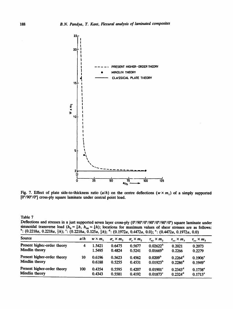
Fig. 3. Effect of plate side-to-thickness ratio (a/h) on the centre deflections (w x m, ) of a simply supported [00/900/900/0 °] cross-ply square laminate under sinusoidal transverse load.
0"8
0.7
T ~' 0.6 E X
0-5
%
/
. . . . PRESENT HIGHER-ORDER THEORY
~ . ~ - MINDLIN THEORY
C;. ASSICAL PLATE THEORY
O THREE-DIMENSIONAL ELASTICITY [2q]
A HI~GHER-ORDER SHEAR DEFORMATION THEORY [22]
Q FIRST- ORDER SHEAR DEFORMATION THEORY [22]
0.3 d
I I I I 00 25 50 75 100
a/h •
Fig. 4. Effect of plate side-to-thickness ratio (a/h) on the in-plane normal stress (or x x m2) in a simply supported [0o/900/900/0 °] cross-ply square laminate under sinusoidal transverse load.
186 B.N. Pandya, T. Kant, Flexural analysis of laminated composites
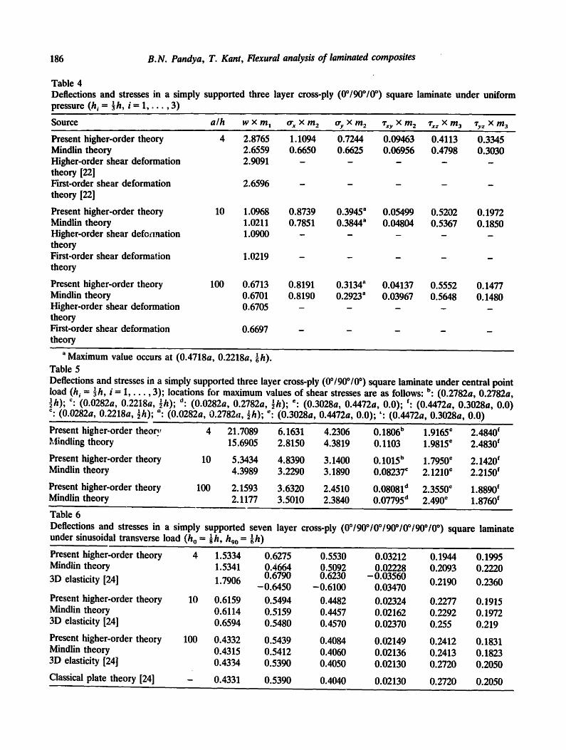
Table 4 Deflections and stresses in a simply supported three layer cross-ply (0°/90°/0 °) square laminate under uniform pressure (hi = ] h, i = 1, . . . . 3)
S o u r c e a l h ;¢ x m 1 or s x m 2 Ory x m 2 ,i.xy x m 2 ,rxz x m a qry z x m 3
Present higher-order theory Mindlin theory Higher-order shear deformation theory [22] First-order shear deformation theory [22]
Present higher-order theory Mindlin theory Higher-order shear defocmation theory First-order shear deformation theory
Present higher-order theory Mindlin theory Higher-order shear deformation theory First-order shear deformation theory
10
100
4 2.8765 1.1094 0.7244 0.09463 0.4113 0.3345 2.6559 0.6650 0.6625 0.06956 0.4798 0.3030 2.9091 . . . . .
2.6596
1.0968 0.8739 0.3945 a 0.05499 0.5202 0.1972 1.0211 0.7851 0.3844 a 0.04804 0.5367 0.1850 1.0900 . . . . .
1.0219
0.6713 0.8191 0.3134 a 0.04137 0.5552 0.1477 0.6701 0.8190 0.2923 a 0.03967 0.5648 0.1480 0.6705 . . . . .
0.6697
a Maximum value occurs at (0.4718a, 0.2218a, ~h). Table 5 Deflections and stresses in a simply supported three layer cross-ply (00/900/0 °) square laminate under central point load (hi - ~h, i = 1 , . . . , 3); locations for maximum values of shear stresses are as follows: b: (0.2782a, 0.2782a, ~h); c: (0.0282a, 0.2218a, ½h); d: (0.0282a, 0.2782a, ½h); e: (0.3028a, 0.4472a, 0.0); f: (0.4472a, 0.3028a, 0.0) c: (0.0282a, 0.2218a, ½h); °: (0.0282a, 0.2782cl, ½h); ~: (0.3028a, 0.4472a, 0.0); ': (0.4472a, 0.3028a, 0.0)
Present higher-order theory Mindling theory
Present higher-order theory Mindlin theory
Present higher-order theory Mindlin theory
4 21.7089 6.1631 4.2306 0.1806 b 1.9165 e 2.4840 f 15.6905 2.8150 4.3819 0.1103 1.9815 e 2.4830 f
10 5.3434 4.8390 3.1400 0.1015 b 1 . 7 9 5 0 e 2.1420 f 4.3989 3.2290 3.1890 0.08237 c 2.1210 ~ 2.2150 f
100 2.1593 3.6320 2.4510 0.080810 2.3550 e 1.8890 f 2.1177 3.5010 2.3840 0.077950 2.490" 1.8760 ~
Table 6 Deflections and stresses in a simply supported seven layer cross-ply (0°/90°/0°/90°/0°/90°/0 °) square laminate under sinusoidal transverse load (ho = ~h, hgo = ~h)
Present higher-order theory 4 Mindlin theory
3D elasticity [24]
Present higher-order theory 10 Mindlin theory 3D elasticity [24]
Present higher-order theory 100 Mindlin theory 3D elasticity [24]
Classical plate theory [24]
1.5334 0.6275 0.5530 0.03212 0.1944 0.1995 1.5341 0.4664 0.5092 0.02228 0.2093 0.2220 1.7906 0.6790 0.6230 - 0.03560
- 0.6450 - 0.6100 0.03470 0.2190 0.2360
0.6159 0.5494 0.4482 0.02324 0.2277 O. 1915 0.6114 0.5159 0.4457 0.02162 0.2292 O. 1972 0.6594 0.5480 0.4570 0.02370 0.255 0.219
0.4332 0.5439 0.4084 0.02149 0.2412 O. 1831 0.4315 0.5412 0.4060 0.02136 0.2413 0.1823 0.4334 0.5390 0.4050 0.02130 0.2720 0.2050
0.4331 0.5390 0.4040 0.02130 0.2720 0.2050
B.N. Pandya, T. Kant, Flexural analysis of laminated composites 187
3.5
4 I 4
2.5- I
t ' I I
g. i I
I I I
1-5- I | t I
0 - 5 -
f 0
\
PRESENT HIGHER- ORDER THEORY
MINOLIN THEORY
CLASSICAL PLATE THEORY
HIGHER -ORDER SHEAR DEFORMATION THEORY [22]
I I 2g sb ?.~ loo 12s alh - -
Fig. 5. Effect of plate side-to-thickness ratio (a/h) on the centre deflections (w x m~) of a simply supported [00/900/0 ° ] cross-ply square laminate under uniform pressure.
1-2
1.1
l 1.0
N E 0 . 9 x
0-8
0.?
I I I I I l l
% \
%
/ /
/
i
. . . . PRESENT HIGHER-ORDER THEORY
'=- - ' - - - MINDLIN THEORY
CLASSICAL PLATE THEORY
0.6 O~ I I I
25 5'0 75 100 alh
Fig. 6. Effect of plate side-to-thickness ratio (a/h) on the in-plane normal stress (o- x x m2) in a simply supported [00/90o/0 °] cross-ply square laminate under uniform pressure.
188 B.N. Pandya, T. Kant, Flexural analysis of laminated composites
E K
22,
20
15,
1.0
5,
2
T 0
I I I I I I I I I I I
J, I
I I I I I I I I ! I I
I I !
I I I I I l
e l
PRESENT HIGHER- ORDER THF.ORY
MINDLIN THEORY
CLASSICAL PLATE THEORY
A
I I I I J 25 50 75 I00 125
alh ~
Fig. 7. Effect of plate side-to-thickness ratio (a/h) on the centre deflections (w x ml ) of a simply supported [00/90o/0 °] cross-ply square laminate under central point load.
Table 7 Deflections and stresses in a just supported seven layer cross-ply (0°190°10°190°10°/90°10") square laminate under sinusoidal transverse load (ho = -~h, hgo = ~h); locations for maximum values of shear stresses are as follows: b: (0.2218a, 0.2218a, ½h); =: (0.2218a, 0.125a, ½h); d: (0.1972a, 0.4472a, 0.0); ~" (0.4472a, 0.1972a, 0.0)
Source a/h
Present higher-order theory 4 Mindlin theory
Present higher-order theory 10 Mindlin theory
Present higher-order theory 100 Mindlin theory
w x m I or x x m 2 % x m 2 cxy x m 2 r~z x m 3 ,ry z x m 3
1.5421 0.6475 0.5677 0.02622 b 0.2021 0.2073 1.5495 0.4824 0.5241 0.01669 b 0.2266 0.2279
0.6196 0.5623 0.4562 0.0209 b 0.2264 d 0.1906 e 0.6188 0.5255 0.4531 0.01923 b 0.2286 d 0.1949 e
0.4354 0.5595 0.4207 0.01901 c 0.2343 d 0.1738 e 0.4343 0.5581 0.4192 0.01873 c 0.2324 d 0.1713 e
B.N. Pandya, T, Kant, Flexural analysis of laminated co,nposites 189
T 5
E x
~g4
PRESENT HiGHER-ORDER THEORY t . . . . . MINDLIN THEORY
" - - - ' - - - CLASSICAL PLATE THEORY
\ \
%
, . ~ , o . , ~ = ~ . ~ = , . . . . . = . = , . . - , . ~ - ~ . ~ ' o ~ ~-,. . ~ : . ~ - .
/ -
2
0~ , , ! . . . . . o , A so 7's ' IO0 alh
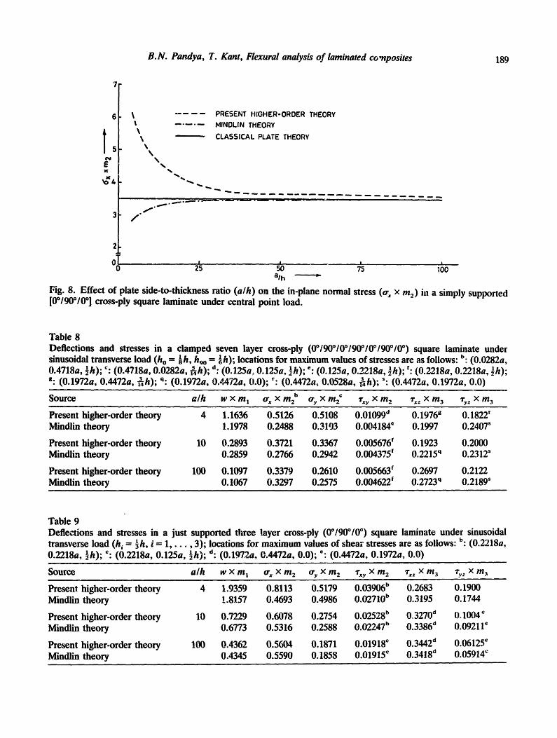
Fig. 8. Effect of plate side-to-thickness ratio (a/h) on the in-plane normal stress (or~ × m2) i~1 a simply supported [0°/90°/0 ° ] cross-ply square laminate under central point load.
Table 8 Deflections and stresses in a clamped seven layer cross-ply (0°190°10°190°10°190°/0°) square laminate under sinusoidal transverse load ( h o - -~h, hgo = -~ h); locations for maximum values of stresses are as follows: b (0.0282a, 0.4718a, ½h); c: (0.4718a, 0.0282a, ~4h); d: (0.125a,, 0.125a, ½h); =" (0.125a, 0.2218a, ½h); f: (0.2218a, 0.2218a, ~h); g: (0.1972a, 0.4472a, 3 h ) ; q: (0.1972a, 0.¢472a, 0.0); r: (0.4472a, 0.0528a, ~ h ) ; ": (0.4472a, 0.1972a, 0.0)
Source a /h w X m I or x X m2 b o'y X m2 c Txy X m 2 "rx= X m 3 1-y z X m 3
Present higher-order theory 4 1.1636 0.5126 0.5108 0.010990 0.1976 g 0.1822 r Mindlin theory 1.1978 0.2488 0.3193 0.004184 e 0.1997 0.2407 s
Present higher-order theory 10 0.2893 0.3721 0.3367 0.095676 f 0.1923 0.2000 Mindlin theory 0.2859 0.2766 0.2942 0.004375 f 0.2215 q 0.2312"
Present higher-order theory 100 0.1097 0.3379 0.2610 0.005663 f 0.2697 0.2122 Mindlin theory 0.1067 0.3297 0.2575 0.004622 f 0.2723 q 0.2189'
Table 9 Deflections and stresses in a just supported three layer cross-ply (0°/90°/0 °) square laminate under sinusoidai transverse load (h i = -~h, i -- 1, . . . . 3); locations for maximum values of shear stresses are as follows: b: (0.2218a, 0.2218a, ½h); c: (0.2218a, 0.125a, ½h); d: (0.1972a, 0.4472a, 0.0); e. (0.4472a, 0.1972a, 0.0)
Source a/h W X m I or x X m 2 ory x m 2 "txy x m 2 lrxz x m 3 ~vz × m 3
Present higher-order theory. 4 1.9359 0.8113 0.5179 0.03906 b 0.2683 0.1900 Mindlin theory !.8157 0.4693 0.4986 0.02710 b 0.3195 0.1744
Present higher-order theory 10 0.7229 0.6078 0.2754 0.025280 0r 3270 d 0.1004 ~ Mindlin theory 0.6773 0.5316 0.2588 0.02247 b 0.3386 d 0.09211 ~
Present higher-order theory 100 0.4362 0.5604 0.1871 0.01918 c 0.3442 d 0.06125 = Mindlin theory 0.4345 0.5590 0.1858 0.01915 ~ 0.3418 ~ 0.05914 e
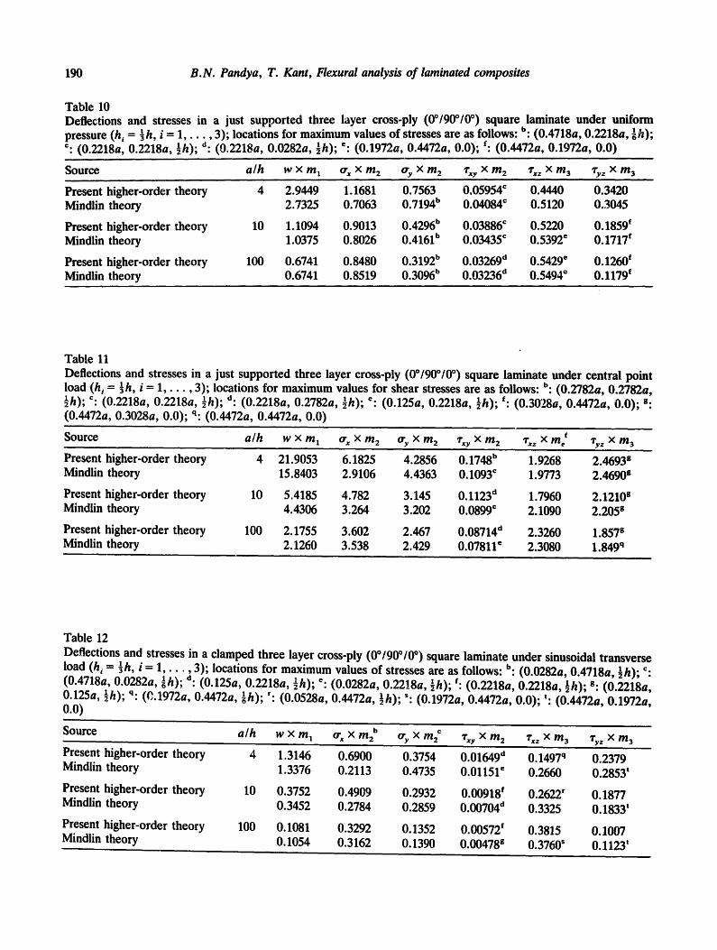
190 B . N . P a n d y a , T. K a n t , Flexural analys i s o f l amina ted c o m p o s i t e s
Table 10 Deflections and stresses in a just supported three layer cross-ply (0°/90°/0 °) square laminate under uniform pressure (h, = ½h, i = 1 , . . . , 3); locations for maximum values of stresses are as follows: b: (0.4718a, 0.2218a, -~h); c: (0.2218a, 0.2218a, ½h); d: (9.2218a, 0.0282a, ½h); e: (0.1972a, 0.4472a, 0.0); f: (0.4472a, 0.1972a, 0.0)
Source a l h W X m 1 trx X m 2 try X m 2 ,rxy X m 2 ,rxz X m 3 ,ty z X m 3
Present higher-order theory 4 2.9449 1.1681 0.7563 0.05954 ~ 0.4440 0.3420 Mindlin theory 2.7325 0.7063 0 . 7 1 9 4 b 0.04084 ~ 0.5120 0.3045
Present higher-order theory 10 1.1094 0.9013 0.4296 b 0.03886 ~ 0.5220 0.1859 f Mindlin theory 1.0375 0.8026 0.4161 b 0.03435 ~ 0.5392 ~ 0.1717 e
Present higher-order theory 100 0.6741 0.8480 0.3192 b 0.03269 d 0.5429 ~ 0.1260 ~ Mindlin theory 0.6741 0.8519 0.3096 b 0.03236 d 0.5494 e 0.1179 ~
Table 11 Deflections and stresses in a just supported three layer cross-ply (00/90°/0 °) square laminate under central point load (h i = ½h, i = 1 , . . . , 3); locations for maximum values for shear stresses are as follows: b: (0.2782a, 0.2782a, ½h); ~: (0.2218a, 0.2218a, ½h); d: (0.2218a, 0.2782a, ½h); e: (0.125a, 0.2218a, ½h); f: (0.3028a, 0.4472a, 0.0); g: (0.4472a, 0.3028a, 0.0); q: (0.4472a, 0.4472a, 0.0)
Source a / h W X m 1 trx x m 2 try X m 2 ~'xy X m 2 ~'xz x me t Ty z x m 3
Present higher-order theory 4 21.9053 6.1825 4.2856 0.1748 b 1.9268 2.4693 g Mindlin theory 15.8403 2.9106 4.4363 0.1093 c 1.9773 2.4690 s
Present higher-order theory 10 5.4185 4.782 3.145 0.1123 d 1.7960 2.1210 s Mindlin theory 4.4306 3.264 3.202 0.0899 c 2.1090 2.205 s
Present higher-order theory 100 2.1755 3.602 2.467 0.08714 d 2.3260 1.857 s Mindlin theory 2.1260 3.538 2.429 0.07811 ~ 2.3080 1.849 q
Table 12 Deflections and stresses in a clamped three layer cross-ply (0°/90°/0 °) square laminate under sinusoidal transverse load (hi = ½h, i = 1, ,3); locations for maximum values of stresses are as follows: b: (0.0282a, 0.4718a, ½h); c: (0.4718a, 0.0282a, ~hi;'d: (0.125a, 0.2218a, ½h); e: (0.0282a, 0.2218a, ½h); ~: (0.2218a, 0.2218a, ½h); s: (0.2218a, 0.125a, ½h); q: (~.1972a, 0.4472a, ~h); ': (0.0528a, 0.4472a, ½h); s: (0.1972a, 0.4472a, 0.0); t: (0.4472a, 0.1972a, 0.0)
Source
Present higher-order theory Mindlin theory
Present higher-order theory Mindlin theory
Present higher-order theory Mindlin theory
a / h w x m 1 trx x m 2 b try x m 2 ~'xy × m 2 'rxz × m3 ,i-y z x m3
4 1.3146 0.6900 0.3754 0.01649 e 0.1497 q 0.2379 1.3376 0.2113 0.4735 0.01151 e 0.2660 0.2853'
10 0.3752 0.4909 0.2932 0.00918 f 0.2622' O. 1877 0.3452 0.2784 0.2859 0.00704 d 0.3325 O. 1833 t
100 0.1081 0.3292 0.1352 0.00572 ~ 0.3815 0.1007 0.1054 0.3162 0.1390 0.00478 s 0.3760 s 0.1123'
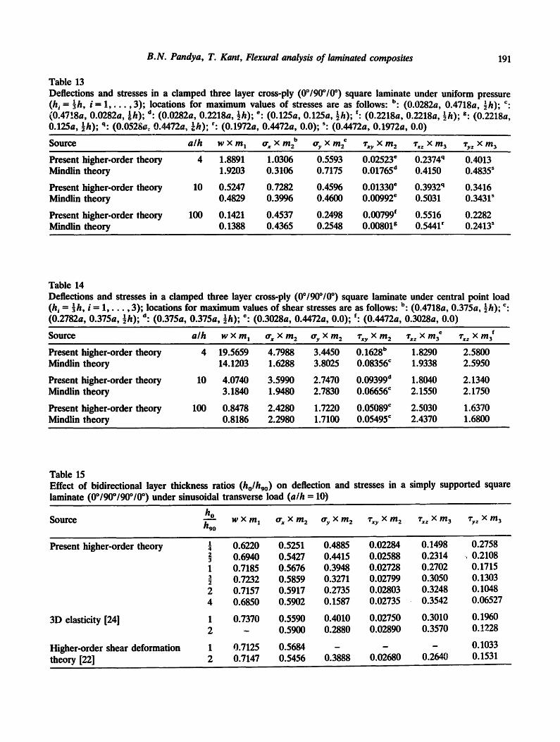
B.N. Pandya, T. Kant, Flexural analysis of laminated composites 191
Table 13 Deflections and stresses in a clamped three layer cross-ply (00/90°/0 °) square laminate under uniform pressure (h i = ~h, i = 1 , . . . , 3); locations for maximum values of stresses are as follows: b: (0.0282a, 0.4718a, ½h); c: (0.47!8a, 0.0282a, ~h); d: (0.0282a, 0.2218a, ½h); ¢" (0.125a, 0.125a, ½h); ~: (0.2218a, 0.2218a, -~h); g: (0.2218a, 0.125a, ½h); q: (0.052go~ 0,4472a, ~h); r: (0.1972a, 0,4472a, 0.0); s: (0.4472a, 0.1972a, 0.0)
S o u r c e a/h w x m I trx x m 2 b try x m 2 ,rxy x m 2 ,r,c z x m 3 qry z x m 3
Present higher-order theory 4 1.8891 1.0306 0.5593 0.02523 e 0.2374 q 0.4013 Mindlin theory 1.9203 0.3106 0.7175 0.01765 d 0.4150 0.4835 s
Present higher-order theory 10 0.5247 0.7282 0.4596 0.01330 ¢ 0.3932 q 0.3416 Mindlin theory 0.4829 0.3996 0.4600 0.00992 ¢ 0.5031 0.3431 s
Present higher-order theory 100 0.1421 0.4537 0.2498 0.00799 ~ 0.5516 0.2282 Mindlin theory 0.1388 0.4365 0.2548 0.00801 s 0.5441 r 0.2413 s
Table 14 Deflections and stresses in a clamped three layer cross-ply (0°/900/0 °) square laminate under central point load (h i = ~ h , i - 1 , . . . , 3); locations for maximum values of shear stresses are as follows: b: (0.4718a, 0.375a, ½h); ¢: (0.2782a, 0.375a, ½h); o: (0.375a, 0.375a, ½h); e. (0.3028a, 0.4472a, 0.0); ~: (0.4472a, 0.3028a, 0.0)
Source a/h w x m~ trx x m 2 try × m 2 ,rxy × m 2 ,rxz × m 3 e Txz x m 3 f
Present higher-order theory 4 19.5659 4.7988 3.4450 0.1628 b 1.8290 2.5800 Mindlin theory 14.1203 1.6288 3.8025 0.08356 c 1.9338 2.5950
Present higher-order theory 10 4.0740 3.5990 2.7470 0.09399 d 1.8040 2.1340 Mindlin theory 3.1840 1.9480 2.7830 0.06656 c 2.1550 2.1750
Present higher-order theory 100 0.8478 2.4280 1.7220 0.05089 ¢ 2.5030 1.6370 Mindlin theory 0.8186 2.2980 1.7100 0.05495 ¢ 2.4370 1.6800
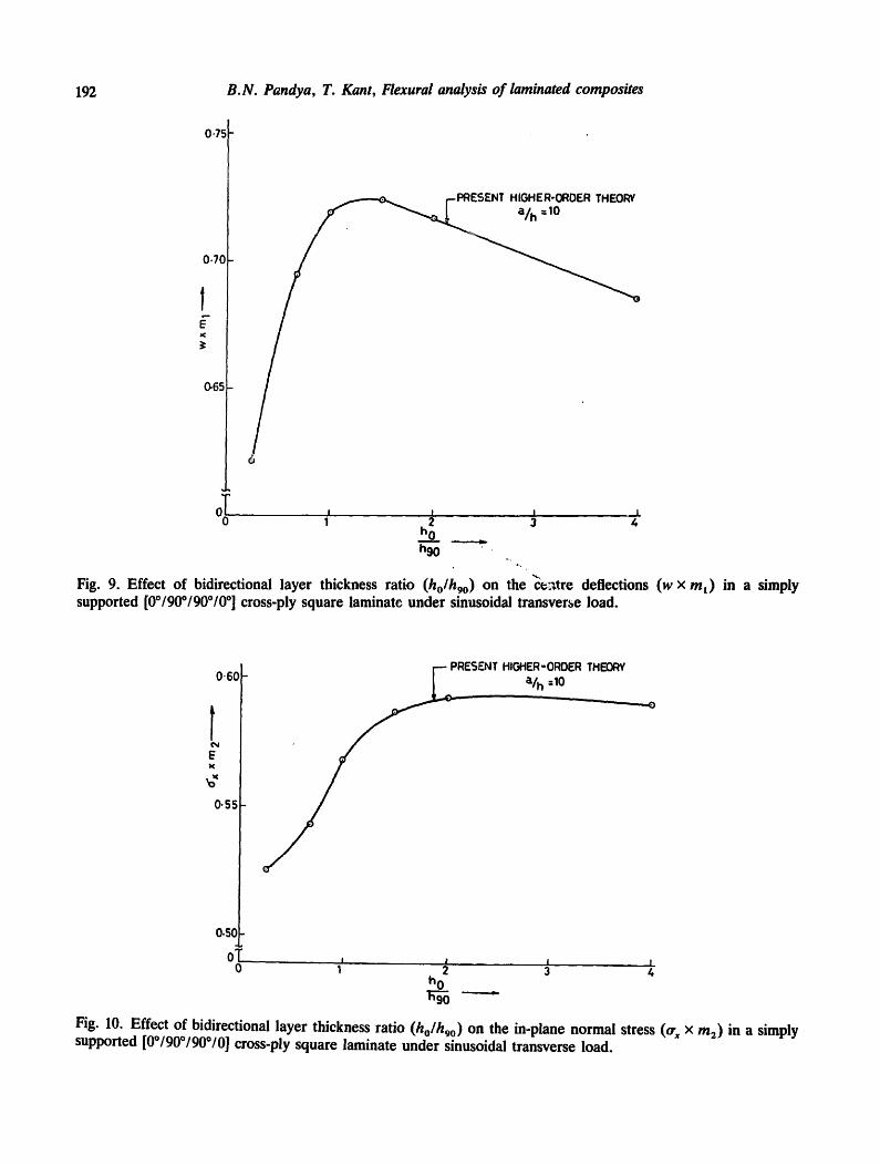
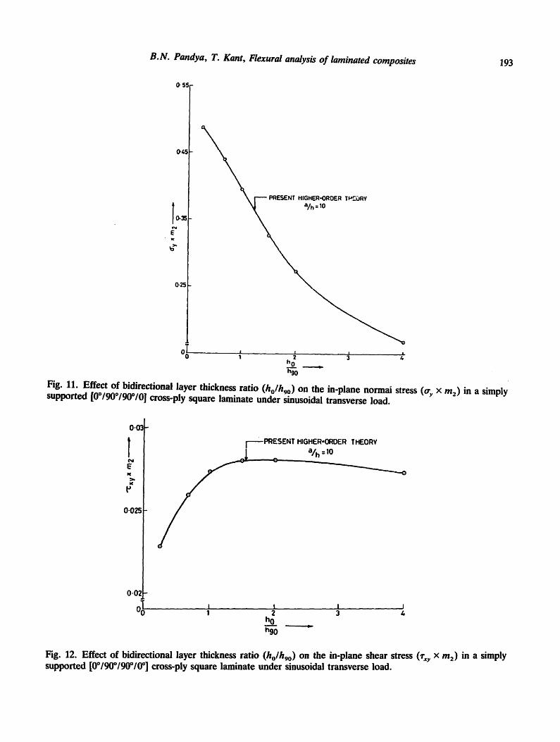
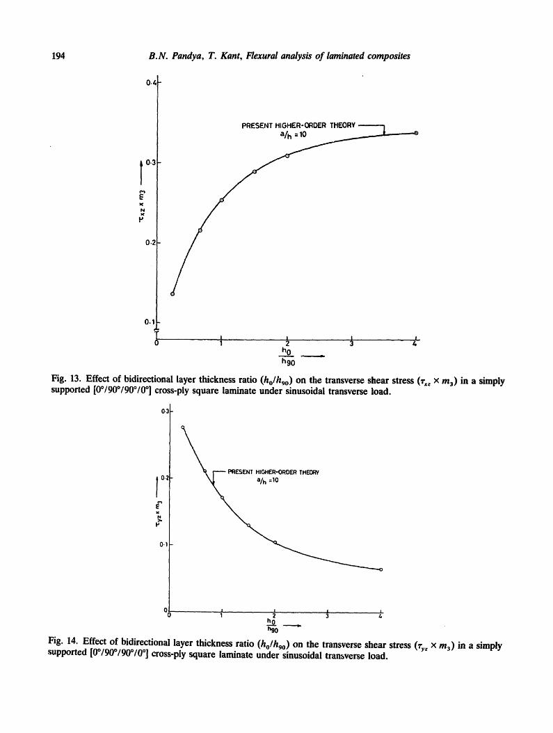
Table 15 Effect of bidirectional layer thickness ratios (ho/hgo) o n deflection and stresses in a simply supported square laminate (0°/90°/90°/0 °) under sinusoidal transverse load (a/h = 10)
h o Source h 9 ° w × m ~ trx x m 2 try x m 2 ,rxy x m 2 ~'xz x m 3 ,ry z x m 3
Present higher-order theory ! 0.6220 0.5251 0.4885 0.02284 0.1498 0.2758 4
2 0.6940 0.5427 0.4415 0.02588 0.2314 0.2108 1 0.7185 0.5676 0.3948 0.02728 0.2702 0.1715 3 0.7232 0.5859 0.3271 0.02799 0.3050 0.1303 2 0.7157 0.5917 0.2735 0.02803 0.3248 0.1048 4 0.6850 0.5902 0.1587 0.02735 0.3542 0.06527
3D elasticity [24] 1 0.7370 2
Higher-order shear deformation 1 0.7125 theory [22] 2 0.7147
0.5590 0.4010 0.02750 0.3010 O. 1960 0.5900 0.2880 0.02890 0.3570 O. 1228
0.5684 - - - 0.1033 0.5456 0.3888 0.02680 0.2640 0.1531
0"75
0.70
I--PRESENT HIGHER-ORDER THEORY
0-65
192 B.N. Pandya, T. Kant, Flexural analysis of laminated composites
O0 ~ ,.. i . . . . I . I ,,. I 1 2 3 4
h 0
h 9 0 •
Fig. 9. Effect of bidirectional layer thickness ratio (holhgo) on the centre deflections (w x m~) in a simply supported [00/900/90010 °] cross-ply square laminate under sinusoidal transverse load.
0"60
l E
0.5~
0.5(
ECJENT HIGHER-ORDER THEORY
a/h =10
o T ~ I I _ • I 0 1 2 3 4
h o ~ - ~ - - - - - . .
Fig. I0. Effect of bidirectional layer thickness ratio (ho/hgo) on the in-plane normal stress (o- x x m2) in a simply supported [0°/90°/90°/0] cross-ply square laminate under sinusoidal transverse load.
O" 55-
0'4
193
['----PRESENT HIGHER-ORDER T~EORY =
[0-3~
E z¢
0.25
OTo
B.N. Pandya, T. Kant, Flexural analysis of laminated composites
h0 = h90
Fig. 11. Effect of bidirectional layer thickness ratio (ho/hgo) on the in-plane normal stress (o-y x m2) in a simply supported [0°/90°/90°/0] cross-ply square laminate under sinusoidal transverse load.
0'03-
T N
E
K
P
0.025
0-0', -
~0 III
i - PRESENT HIGHER-ORDER THEORY
J ~ a/h =I0
I t I | I 2 3 4
h 0
h90
Fig. 12. Effect of bidirectional layer thickness ratio (ho/h9o) on the in-plane shear stress 0"xy x m2) in a simply supported [00/900/900/0 °] cross-ply square laminate under sinusoidal transverse load.
194 B.N. Pandya, T. Kant, Flexural analysis of laminated composites
0.~
T 0 . 3
E
N
0 . 2
0.1
T 0
PRESENT HIGHER-ORDER THEORY -'--"-'1
/ | . I I I
1 2 3 4 ho _ h90
Fig. 13. Effect of bidirectional layer thickness ratio (holhgo) on the transverse shear stress 0"xz x m3) in a simply supported [0°/90°/90°/0°] cross-ply square laminate under sinusoidal transverse load.
0.3
0.t
~ [ ~- PRESENT HIGHER-ORDER THEORY
00 ~ . . . . . . . . . . . . . . . . ~ . . . . . . . . . . . . . . , ........... i 3
h 9 0
Fig. 14. Effect of bidirectional layer thickness ratio (ho/hgo) on the transverse shear stress 0"yz x m3) in a simply supported [0°/90°/90°/0 o] cross-ply square laminate under sinusoidal transverse load.

B.N. Pandya, T. Kant, Flexural analysis of laminated composites 195
EXAMPLE 4.5. This example is selected to bring-out the effect of bidirectional layer thickness ratios (ho/h9o) o n the response of a simply supported four-layer cross-ply (0°/90°/ 90°/0 °) square plate under sinusoidal transverse load. The numerical results are presented in Table 15 for a plate with aspect ratio of 10. The variations of centre deflection (w), in-plane normal and shear stresses (crx, cry, ~xy), and transverse shear stresses (~z, ~yz) with the bidirectional layer thickness ratios are presented in Figs. 9-14, respectively.
$. Conclusions
A refined higher-order theory and Mindlin's theo~ are used for flexural analysis of symmetrically laminated square composite plates. A C o continuous finite element model of the present higher-order theory is developed and validated by comparisons with the available three-dimensional elasticity and the closed-form plate solutions. It is reasonably clear from the convergence study that a two by two mesh with 9-noded Lagrangian quadrilaterals in a quarter plate gives sufficiently accurate predictions of displacement and stresses for all practical purposes. Numerical results are presented for various commonly used boundary conditions and loading cases, some of which should serve as benchmarks for future investigators. The result of Example 4.5 may be of importance to the designers in the field of laminated composite constructions. The effects of neglecting shear deformation (as in classical lamina- tion theory) and considering constant shear deformation (as in classical first-order shear deformation Mindlin-Reissner theories) on the response of laminated composite plates are investigated for thin to moderately thick plates. In contrast to the classical shear deformation theories, the present higher-order theory does not require shear correction coefficient due to more realistic representation of the cross-sectional deformation. In addition, the present theory includes the effect of direct normal stress in the thickness direction (cry) which is, though negligible, very important to study the delamination mode of failure in laminated composites. The basic foundations of this theory for the laminated anistropic composite plates, the resulting C O finite element formulation, and most of the numerical results are being presented for the first time.
Appendix A. Elements of matrix [C]
E l ( 1 - v32 v23) C l l = A '
E3(v 3 + v23) Cl3 = A
E3(v23 + /J13V21) C23" A
= C22 =
E2(lPI2 -~- v13 ]732) C12" A = C21'
E2(1 - v31 vl3)
= =
A
E 3 ( 1 - vt2v21) a
C44- GI2 , C55 - G23 , C66" G13,
Where
A-(1- / /23v32 -/J121721-//13//31-//12v23v31- v13v32 v21),
196
E 2 v21 = E--'~ vn '
B.N. Pandya, T. Kant, Flexural analysis of laminated composites
E3 E3 v32 = ~ v23, v31 = E~ v13.
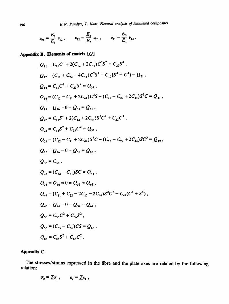
Appendix B. Elements
QI! -" Cll c4
QI2
Q13
Q14
Q15
Q22
Q23
Q24 "-
of matrix [ Q]
+ 2(C,2 + 2C44)C2S 2 + C22 $4 ,
" - (C, , + ( ]22- 4C44)C2S 2 + C12( $4 "~" C 4 ) = Q2,,
= C13 C2 + C23 $2= Q31 ,
=.(C,2- C,, 4" 2C44)C3S- (C21- C22 4- 2C44)S3C-~ Q4, ,
= Q16 = 0 = Q51 = Q61,
Cll $4 "1- 2(C,2 + 2C44)S 2C2 J¢ C22 c4 ,
el3 $2 + C23 C 2 = Q32,
(C12- Cll "l- 2C44)$3C- (C12- C22 4" 2C44)SC 3"- Q42,
Q25 "-- Q26 = 0 = Q52 = Q62,
Q 33 ~ C33
Q34 = (C32- C31)SC= Q43,
Q 35 ~ Q36
Q44 = (Cll
= 0 = Qsa = Q6a,
+ C22- 2C n -2C44)S2C 2 + C44(C 4 "~- S4) ,
Q45- Q46 = 0 = Qs4 = Q64,
Q55 = c55 C2 + c66 s2 ,
= c )cs = ,
Q66 = C55 S2 + C66 c2.
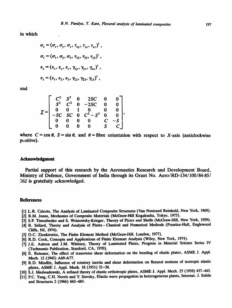
Appendix C
The stresses/strains expressed in the fibre and the plate axes are related by the following relation:
Crx = _Tcrl, ex - T~I ,
B.N. Pandya, T. Kant, Flexural analysis of laminated composites 197
in which
and
Crx = %, %,
0.1 = (0.1' 0"2' 0"3' T12' "/'23' '713) t '
x=(ex, e , , ,
E1 = (E l ' e2 ' E3' q/12' Y23' "Y13) t '
D
C 2 S 2 0 2SC 0 O- S 2 C 2 0 - 2 S C 0 0 0 0 1 0 0 0
- S C S C 0 C 2 - S 2 0 0
0 0 0 0 C - S 0 0 0 0 S C
m
where C = cos 0, S = sin 0, and 0 =fibre orientation with respect to X-axis (anticlockwise positive).
Acknowledgment
Partial support of this research by the Aeronautics Research and Development Board, Ministry of Defence, Government of India through its Grant No. Aero/RD-134/100/84-85/ 362 is gratefully acknowledged.
References
[10] [111
[1] L.R. Calcote, The Analysis of Laminated Composite Structures (Van Nostrand Reinhold, New York, 1969). [2] R.M. Jones, Mechanics of Composite Materials (McGraw-Hill Kogakusha, Tokyo, 1975). [3] S.P. Timoshenko and S. Woinowsky-Krieger, Theory of Plates and Shells (McGraw-Hill, New York, 1959). [4] R. Szilard, Theory and Analysis of Plates-Classical and Numerical Methods (Prentice-Hall, Englewood
Cliffs, N J, 1974). [5] O.C. Zienkiewicz, The Finite Element Method (McGraw-HilL London, 1977). [6] R.D. Cook, Concepts and Applications of Finite Element Analysis (Wiley, New York, 1974). [7] J.E. Ashton and J.M. Whitney, Theory of Laminated Plates, Progress in Material Science Series IV
(Technomic Publication, Stanford, CA, 1970). [8] E. Reissner, The effect of transverse shear deformation on the bending of elastic plates, ASME J. Appl.
Mech. 12 (1945) A69-A77. [9] R.D. Mindlin, Influence of rotatory inertia and shear deformation on flexural motions of isotropic elastic
plates, ASME J. Appl. Mech. 18 (1951) 31-38. S.J. Medwadowski, A refined theory of elastic orthotropic plates, ASME J. Appl. Mech. 25 (1958) 437-443. P.C. Yang, C.H. Norris and Y. Stavsky, Elastic wave propagation in heterogeneous plates, Internat. J. Solids and Structures 2 (1966) 665-684.

198 B.N. Pandya, T. Kant, Flexural analysis of laminated composites
[12]
[13]
[14]
[15] [16]
[17]
[181
[19]
[2O]
[21]
[22]
[23]
[24]
[25]
[26]
E. Reissner, On transverse bending of plates, including the effects of transverse shear deformation, Internat. J. Solids and Structures 11 (1975) 569-573. K.H. Lo, R.M. Christensen and E.M. Wu, A high-order theory of plate deformation - Part 1: Homogeneous plates, ASME J. Appl. Mech. 44 (1977) 663-668. K.H. Lo, R.M. Christensen and E.M. Wu, A high-order theory of plate deformation-Part 2: Laminated plates, ASME J. Appl. Mech. 44 (1977) 669-676. T. Kant, Numerical analysis of thick plates, Comput. Meths. Appl. Mech. Engrg. 31 (1982) 1-18. T. Kant, D.R.J. Owen and O.C. Zienkiewicz, A refined higher-order C O plate bending element, Comput. & Structures 15 (1982) 177-183. B.N. Pandya and T. Kant, A refined higher-order generally orthotropic C o plate bending element, Comput. & Structures (to appear). C.W. Bert, A critical evaluation of new plate theories applied to laminated composites, Composite Structures 2 (1984) 329-347. N.D. Phan and J.N. Reddy, Analysis of laminated composite plates using a higher-order shear deformation theory, Internat. J. Numer. Meths. Engrg. 21 (1985) 2201-2219. M. Levinson, An accurate, simple theory of the statics and dynamics of elastic plates, Mech. Res. Comm. 7 (1980) 343-350. M.VN. Murthy, An improved transverse shear deformation theory for laminated anisotropic plates, NASA Technical Paper 1903, 1981. J.N. Reddy, A simple higher-order theory for laminated composite plates, ASME J. Appi. Mech. 51 (1984) 745-752. J.M. Whitney, Delamination in composite materials, in: Proceedings of 19th Mid-Western Mechanics Conference, Ohio State University, Columbus, OH (1985) 217-18. N.J. Pagano and S.J. Hatfield, Elastic behaviour of multilayered bidirectional composites, AIAA J. 10 (1972) 931-933. A.K. Gupta and B. Mohraz, A method of computing numerically integrated stiffness matrices, Internat. J. Numer. Meths. Engrg. 5 (1972) 83-89. T. Kant and N.P. Sahani, Fibre reinforced plates- some studies with 9-noded Lagrangian/Heterosis element, in: Transactions 8th International Conference on Structural Mechanics in Reactor Technology (SMiRT-8), Brussels, Belgium (1985) 315-320.


![Free vibration of higher-order sandwich and composite ...tkant/papers/TKant-IITB-JP115.pdf · Bhashyam and Prathap [4] detected the second spectrum of frequencies, known as shear](https://img.dokumen.tips/doc/110x75/5e92d65352e8136d4b782412/free-vibration-of-higher-order-sandwich-and-composite-tkantpaperstkant-iitb-jp115pdf.jpg)


![Thermal flexural analysis of cross-ply laminated plates ... · thermal load has been developed by Kant, et al.[9]. Three dimensional thermal analysis of compo-site laminated plates](https://img.dokumen.tips/doc/110x75/5f9764cbc950ca46747a71af/thermal-flexural-analysis-of-cross-ply-laminated-plates-thermal-load-has-been.jpg)