Embed Size (px)
Citation preview

www.advmat.dewww.MaterialsViews.com
CO
MM
UN
ICATI
Flexible Pyroelectric Nanogenerators using a Composite Structure of Lead-Free KNbO 3 Nanowires
Ya Yang , Jong Hoon Jung , Byung Kil Yun , Fang Zhang , Ken C. Pradel , Wenxi Guo , and Zhong Lin Wang *
ON
Energy-harvesting and conversion devices using nanotech-nology have received increasing interest recently because they have potential applications in self-powered nanodevices and nanosystems. [ 1–3 ] Piezoelectric nanowires have been extensively investigated for nanogenerators (NGs). [ 4–7 ] The nanowire-based solar cells can only work under light-illumination condi-tions. [ 8–10 ] Owing to the small sizes, it is diffi cult for nanowire thermoelectric devices to maintain the temperature difference across a nanoscale distance. [ 11 ] An alternative approach is to use pyroelectric-based energy harvesting, where the tempera-ture dependence of the spontaneous polarization can result in the fl ow of electrons for electric output. [ 12–14 ] Moreover, it has been reported that a size-driven enhancement of the pyroelec-tric coupling leads to a giant pyroelectric current and voltage generation by the polarized ferroelectric nanomaterials in response to temperature fl uctuations. [ 15 ] It has been reported that the spontaneous polarization and the pyroelectric coeffi -cient of bulk KNbO 3 are about 0.41 C/m 2 and 5 nC/cm 2 K at 300 K, respectively. [ 16 ] Although there have been some studies about the piezoelectric property of KNbO 3 materials and its applications, [ 17 , 18 ] there have been no reports about KNbO 3 -nanowire-based pyroelectric NGs. PZT nanomaterials may be a good choice for pyroelectric NGs due to their large pyroelectric coeffi cient. [ 12 ] However, it is important to explore cost-effective pyroelectric NGs by using easily accessible and non-toxic ferroelectric nanowires. [ 19 , 20 ]
In this work, we report pyroelectric NGs fabricated using lead-free KNbO 3 nanowires, for the fi rst time. The grown KNbO 3 nanowires have a single-crystalline structure with a growth direction of [011]. By forming a composite of KNbO 3 nanowires with polydimethylsiloxane (PDMS) polymer, fl ex-ible NGs were fabricated easily after applying a direction poling
© 2012 WILEY-VCH Verlag Gm
Dr. Y. Yang, Dr. J. H. Jung, F. Zhang, K. C. Pradel, W. Guo, Prof. Z. L. WangSchool of Materials Science and Engineering Georgia Institute of Technology Atlanta, GA 30332, USA E-mail: [email protected] Prof. Z. L. WangBeijing Institute of Nanoenergy and Nanosystems Chinese Academy of Sciences Beijing, PR China Prof. J. H. Jung, B. K. YunDepartment of Physics Inha University Incheon 402-751, Republic of Korea
DOI: 10.1002/adma.201201414
Adv. Mater. 2012, DOI: 10.1002/adma.201201414
process. The mechanisms of pyroelectric NGs are discussed. The NGs were also used to harvest energy from sunlight illumi-nation and fabricate hybrid NGs with solar cells.
We fabricated a composite of the KNbO 3 nanowires and PDMS polymer in a volume ratio of 3:7 to imbue our NGs with fl exibilty. The pyroelectric device mainly consists of three layers, as schematically shown in Figure 1 a. The Ag and ITO fi lms act as top and bottom electrodes, respectively. As described in the experimental section, the KNbO 3 nanowires were grown by a simple hydrothermal method. Figure 1 b shows a transmission electron microscopy (TEM) image of single KNbO 3 nanowires. The corresponding selected area electron diffraction (SAED) pattern confi rms that the phase is of the perovskite structure. The high-resolution transmission electron microscopy (HR-TEM) image indicates that the nanowires are single-crystalline and free of defects. Combining the SAED patterns and HR-TEM images, the growth direction of the nanowire is con-fi rmed to be along the [011] direction. Due to the use of PDMS polymer layer in NGs, the devices are fl exible and can be bent, as shown in Figure 1 c. The SEM image of a single KNbO 3 nanowire in Figure 1 d shows that the surface of the nanowire is clean and the diameter is about 150 nm. Figure 1 e shows an enlarged cross-sectional SEM image of a KNbO 3 nanowire-PDMS polymer composite. It can be clearly seen that the nanowires were randomly oriented and well-dispersed without aggregations.
After a positive direction poling process, the electric dipoles in KNbO 3 nanowires would tend to align along the electric-fi eld direction from top to bottom, as shown in the inset of Figure 2 a. Figure 2 shows the generated open-circuit voltage and short-circuit current under the different changes in temperature. When the temperature increases from room temperature (RT), 295 K, to a higher value, positive current/voltage peaks can be observed. The opposite output is observed when the tempera-ture decreases from RT 295 K to a lower value. Under a change in temperature of about 40 K, the obtained current and voltage peaks were about 120 pA and 10 mV, respectively. The output current/voltage increased with increasing the rate of change in temperature. After a negative direction poling process, the electric dipoles inthe KNbO 3 nanowires would tend to align along the electric-fi eld direction from bottom to top, as shown in the inset of Figure 3 a. The measured open-circuit voltage and short-circuit current of the NG under the different changes in temperature are shown in Figure 3 . Under the same change in temperature, the variation of the voltage/current output for the NGs in Figure 2 and 3 are opposite. The output of the NGs can be increased by increasing the change in temperature. Usu-ally, the output current I of the pyroelectric NGs can be deter-mined by the equation of I = p AdT
dt , where p is the pyroelectric
bH & Co. KGaA, Weinheim 1wileyonlinelibrary.com

2
www.advmat.dewww.MaterialsViews.com
wileyonlinelibrary.com © 2012 WILEY-VCH Verlag GmbH & Co. KGaA, We
CO
MM
UN
ICATI
ON
Figure 2 . a) The cyclic change in the different heated temperatures in the nanogenerator and ta schematic of the negative electric dipoles in the nanogenerators. b) Measured open-circuit vunder the conditions in (a). c) The cyclic change in the different cooled temperatures in the nand) The open-circuit voltage and short-circuit current of the nanogenerator under the conditions
Figure 1 . a) Schematic diagram showing the structure of the pyroelectric nanogenerator. b) TEM image of a single KNbO 3 nanowire, the corresponding SAED pattern of the nanowire, and the corresponding HR-TEM image of the nanowire. c) SEM image of a bent KNbO 3 -PDMS composite fi lm. d) SEM image of a single KNbO 3 nanowire. e) SEM image of the enlarged cross-section of the KNbO 3 -PDMS composite fi lm in (c).
coeffi cient, A is the effective area of the NG, dT/dt is the rate of change in temperature. [ 21 ] The rates of change in temperature are shown in Figure 2 a and 3 a. It can be clearly seen that the output current of the NGs in Figure 2 and 3 can increase with increasing the rate of change in temperature, which is consistent with the equation of output current.
To confi rm that the obtained signals were due to the KNbO 3 nanowires, we performed three control experiments. Firstly, we tested the output voltage from only PDMS polymer without KNbO 3 nanowires after the same pos-itive direction poling process. These was no observed output voltage under the different changes in temperature (Supporting Informa-tion, Figure S1). Secondly, under the different changes of temperature, we tested the output voltage of the NG fabricated from the KNbO 3 nanowire-PDMS polymer composite before (Figure S2a,b) and after (Figure S2c,d) a posi-tive direction poling, respectively. Before the poling process, there was no observed output signal. After the poling process, voltage peaks can be clearly seen in Figure S2c,d. Thirdly, the linear superposition test in Figure S3 shows that the output current of NG could be
inheim
he corresponding differential curves. The inset shows oltage and short-circuit current of the nanogenerator ogenerator and the corresponding differential curves.
in (c).
Adv. Mater. 2012, DOI: 10.1002/adma.201201414
www.advmat.dewww.MaterialsViews.com
CO
MM
UN
ICATIO
N
Figure 3 . a) The cyclic change in the different heated temperatures in the nanogenerator and the corresponding differential curves. The inset shows a schematic of the positive electric dipoles in the nanogenerators. b) The open-circuit voltage and short-circuit current of the nanogenerator under the conditions in a. c) The cyclic change in the different cooled temperatures in the nanogenerator and the corresponding differential curves. d) The open-circuit voltage and short-circuit current of the nanogenerator under the conditions in (c).
enhanced or weakened when the two NGs were connected in parallel with the same polarities or opposite polarities, respec-tively. There results confi rm that the observed output voltage/current was indeed generated by the KNbO 3 nanowires.
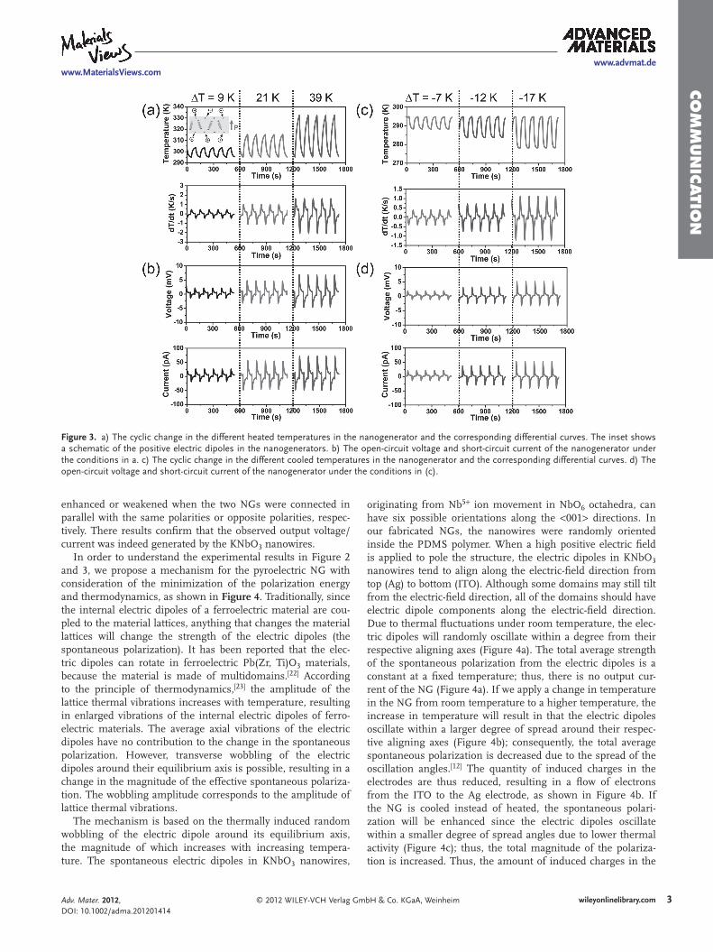
In order to understand the experimental results in Figure 2 and 3 , we propose a mechanism for the pyroelectric NG with consideration of the minimization of the polarization energy and thermodynamics, as shown in Figure 4 . Traditionally, since the internal electric dipoles of a ferroelectric material are cou-pled to the material lattices, anything that changes the material lattices will change the strength of the electric dipoles (the spontaneous polarization). It has been reported that the elec-tric dipoles can rotate in ferroelectric Pb(Zr, Ti)O 3 materials, because the material is made of multidomains. [ 22 ] According to the principle of thermodynamics, [ 23 ] the amplitude of the lattice thermal vibrations increases with temperature, resulting in enlarged vibrations of the internal electric dipoles of ferro-electric materials. The average axial vibrations of the electric dipoles have no contribution to the change in the spontaneous polarization. However, transverse wobbling of the electric dipoles around their equilibrium axis is possible, resulting in a change in the magnitude of the effective spontaneous polariza-tion. The wobbling amplitude corresponds to the amplitude of lattice thermal vibrations.
The mechanism is based on the thermally induced random wobbling of the electric dipole around its equilibrium axis, the magnitude of which increases with increasing tempera-ture. The spontaneous electric dipoles in KNbO 3 nanowires,
© 2012 WILEY-VCH Verlag GmAdv. Mater. 2012, DOI: 10.1002/adma.201201414
originating from Nb 5 + ion movement in NbO 6 octahedra, can have six possible orientations along the < 001 > directions. In our fabricated NGs, the nanowires were randomly oriented inside the PDMS polymer. When a high positive electric fi eld is applied to pole the structure, the electric dipoles in KNbO 3 nanowires tend to align along the electric-fi eld direction from top (Ag) to bottom (ITO). Although some domains may still tilt from the electric-fi eld direction, all of the domains should have electric dipole components along the electric-fi eld direction. Due to thermal fl uctuations under room temperature, the elec-tric dipoles will randomly oscillate within a degree from their respective aligning axes (Figure 4 a). The total average strength of the spontaneous polarization from the electric dipoles is a constant at a fi xed temperature; thus, there is no output cur-rent of the NG (Figure 4 a). If we apply a change in temperature in the NG from room temperature to a higher temperature, the increase in temperature will result in that the electric dipoles oscillate within a larger degree of spread around their respec-tive aligning axes (Figure 4 b); consequently, the total average spontaneous polarization is decreased due to the spread of the oscillation angles. [ 12 ] The quantity of induced charges in the electrodes are thus reduced, resulting in a fl ow of electrons from the ITO to the Ag electrode, as shown in Figure 4 b. If the NG is cooled instead of heated, the spontaneous polari-zation will be enhanced since the electric dipoles oscillate within a smaller degree of spread angles due to lower thermal activity (Figure 4 c); thus, the total magnitude of the polariza-tion is increased. Thus, the amount of induced charges in the
3wileyonlinelibrary.combH & Co. KGaA, Weinheim
www.advmat.dewww.MaterialsViews.com
CO
MM
UN
ICATI
ON
Figure 4 . Proposed mechanism of the pyroelectric nanogenerator based on a composite structure of pyroelectric nanowires. a–c) Schematic dia-grams of the pyroelectric nanogenerator with negative electric dipoles under room temperature (a), heated (b) and cooled (c) conditions. The angles marked in the diagrams represent the degrees to which the dipole would oscillate as driven by statistical thermal fl uctuations. The larger the wobbling angle is, the smaller is the polarization.
electrodes are increased. In such a case, electrons will fl ow from the Ag to the ITO electrode, as shown in Figure 4 c.
Alternatively, when a negative electric fi eld is applied for the poling, the electric dipoles tend to align along the electric fi eld direction from the bottom (ITO) to the top (Ag). For this case, due to the opposite direction of electric dipoles as compared with that in Figure 4 a, the output signals will reverse in compar-ison to the above case, according to the explanation in Figure 4 . The mechanism in Figure 4 is consistent with the experimental results in Figure 2 and 3 .
The pyroelectric coeffi cient of the fabricated composite structure (the KNbO 3 nanowires and PDMS polymer in a volume ratio of 3:7) is about 0.8 nC/cm 2 K, which is smaller than that of bulk KNbO 3 (5 nC/cm 2 K at 300 K). [ 16 ] This is due to the PDMS polymer in the NGs, since it has no pyro-electric effect. Although the addition of PDMS polymer in the NGs will decrease the total output, it can increase the fl ex-ibility of the NGs, which is important for developing fl exible energy-harvesting devices.
4 wileyonlinelibrary.com © 2012 WILEY-VCH Verlag G
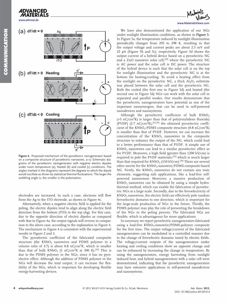
We have also demonstrated the application of our NGs under sunlight illumination conditions, as shown in Figure 5 . In Figure 5 a, the temperature induced by sunlight illumination periodically changes from 295 to 298 K, resulting in that the output voltage and current peaks are about 2.5 mV and 25 pA (Figure 5 b and 5 c), respectively. Figure 5 d shows the output current of a hybrid device based on a pyroelectric NG and a ZnO nanowire solar cell, [ 10 ] where the pyroelectric NG is AC power and the solar cell is DC power. The structure of the hybrid device is such that the solar cell is on the top for sunlight illumination and the pyroelectric NG is at the bottom for heating/cooling. To avoid a heating effect from the sunlight on the pyroelectric NG, a thick Al 2 O 3 substrate was placed between the solar cell and the pyroelectric NG. Both the cooled (the fi rst one in Figure 5 d) and heated (the second one in Figure 5 d) NGs can work with the solar cell in separated and parallel modes. Our results demonstrate that the pyroelectric nanogenerators have potential as one of the important nanoenergies, that can be used in self-powered nanodevices and nanosystems.
Although the pyroelectric coeffi cient of bulk KNbO 3 ( > 5 nC/cm 2 K) is larger than that of poly(vinylidene fl uoride) (PVDF) (2.7 nC/cm 2 K), [ 16 , 24 ] the obtained pyroelectric coeffi -cient of the KNbO 3 -PDMS composite structure (0.8 nC/cm 2 K) is smaller than that of PVDF. However, we can increase the concentration of the KNbO 3 nanowires in the composite structure to enhance the output of the NG, which could lead to a better performance than that of PVDF. A simple use of KNbO 3 nanowires can lead to a similar pyroelectric effect as for PVDF. Moreover, a high fi eld (greater than 1200 kV/cm) is required to pole the PVDF materials, [ 25 ] which is much larger than that required for KNbO 3 (150 kV/cm) . [ 26 ] There are several other merits for the KNbO 3 -nanowire/PDMS-composite-based NG. Firstly, the KNbO 3 nanowires do not contain any toxic elements, suggesting safe applications, like a lead-free self-powered nanosensor. Moreover, a massive production of KNbO 3 nanowires can be obtained by using a simple hydro-thermal method, which can enable the fabrication of pyroelec-tric NGs at a large scale. Secondly, due to the ferroelectricity of KNbO 3 nanowires, the electric fi eld can effectively pole random ferroelectric domains to one direction, which is important for the large-scale production of NGs in the future. Thirdly, the PDMS polymer may play the role of preventing the breakdown of the NGs in the poling process. The fabricated NGs are fl exible, which is advantageous for more applications.
In summary, we report pyroelectric nanogenerators fabricated using a lead-free KNbO 3 -nanowire/PDMS-polymer composite for the fi rst time. The output voltage/current of the fabricated nanogenerators can be modulated in a controlled manner due to the change of ferroelectric domains tuned by electric fi elds. The voltage/current outputs of the nanogenerators under heating and cooling conditions show an opposite change and can be enhanced by increasing the change in temperature. By using the nanogenerators, energy harvesting from sunlight induced heat, and hybrid nanogenerators with a solar cell were demonstrated, indicating that the pyroelectric nanogenerators may have extensive applications in self-powered nanodevices and nanosystems.
mbH & Co. KGaA, Weinheim Adv. Mater. 2012, DOI: 10.1002/adma.201201414
www.advmat.dewww.MaterialsViews.com
CO
MM
UN
ICATIO
N
Figure 5 . a) The cyclic change in the different heated temperatures in the nanogenerator from sunlight illumination and the corresponding differential curves. b,c) Measured open-circuit voltage and short-circuit current of the pyroelectric nanogenerator at forward connection (b) and reversed con-nection (c) to the measurement system, when it was subject to the repeated temperature change in (a). d) The output current of the hybrid nanogen-erator based on the parallel P3HT/ZnO nanowire solar cell and pyroelectric nanogenerator under the repeated cooling (top) and heating (bottom) conditions.
Experimental Section Fabrication of the Pyroelectric Nanogenerators : The KNbO 3 nanowires
were synthesized by the hydrothermal method. 0.63 mol of KOH (35.3 g, 90%) was dissolved in the 50 mL of distilled water and then 1.24 mmol of Nb 2 O 5 (0.33 g, 99.99%) was added into the KOH solution. Thoroughly stirred solutions were transferred to a stainless-steel autoclave with a 100 mL Tefl on lining to undergo a hydrothermal reaction at 150 ° C for 6 d. The obtained white powders were further annealed at 400 ° C for 12 h. The annealed KNbO 3 nanowires were thoroughly mixed with polydimethylsiloxane (PDMS) with the volume ratio of 3:7. A KNbO 3 -PDMS composite fi lm of about 200 μ m was fabricated by a spin-coating technique. Ag and ITO served as the top and bottom electrodes, respectively. Note that the electric polarization of KNbO 3 fi lm is almost saturated above 150 kV/cm. [ 26 ] We applied an electric fi eld of about 160 kV/cm for electric poling at room temperature.
Electrical Measurements : All of the electrical characterization measurements of the NGs were conducted after connecting the Ag and ITO layers as electrodes. A thermoelectric-based heater and cooler served to apply a periodic change in temperature to the NGs. A temperature sensor was used to detect the change in temperature in the NGs. The open-circuit voltage and the short-circuit current were measured via voltage and current preamplifi ers (Stanford Research SR570 and SR560), respectively.
Supporting Information Supporting Information is available from the Wiley Online Library or from the author.
© 2012 WILEY-VCH Verlag GmAdv. Mater. 2012, DOI: 10.1002/adma.201201414
Acknowledgements The research was supported by the US Department of Energy, Offi ce of Basic Energy Sciences, Division of Materials Sciences and Engineering under Award DE-FG02-07ER46394, NSF (CMMI 0403671), and the Knowledge Innovation Program of the Chinese Academy of Sciences (Grant No. KJCX2-YW-M13). J.H.J and B.K.Y. were supported by the Korea Research Foundation Grant funded by the Korean Government (MOEHRD) (KRF-2008-313-C00253).
Received: April 6, 2012 Revised: July 6, 2012
Published online:
[ 1 ] J. A. Paradiso , T. Starnerd , IEEE Pervasive Computing 2005 , 4 , 18 . [ 2 ] S. Xu , Y. Qin , C. Xu , Y. G. Wei , R. Yang , Z. L. Wang , Nat. Nano-
technol. 2010 , 5 , 367 . [ 3 ] Y. F. Hu , Y. Zhang , C. Xu , L. Lin , R. L. Snyder , Z. L. Wang , Nano Lett.
2011 , 11 , 2572 . [ 4 ] Z. L. Wang , J. H. Song , Science 2006 , 312 , 242 . [ 5 ] X. D. Wang , J. H. Song , J. Liu , Z. L. Wang , Science 2007 , 316 , 102 . [ 6 ] Y. Qin , X. D. Wang , Z. L. Wang , Nature 2008 , 451 , 809 . [ 7 ] R. S. Yang , Y. Qin , L. M. Dai , Z. L. Wang , Nat. Nanotechnol. 2009 , 4 ,
34 . [ 8 ] B. Tian , X. Zheng , T. J. Kempa , Y. Fang , N. Yu , G. Yu , J. Huang ,
C. M. Lieber , Nature 2007 , 499 , 885 . [ 9 ] Y. Dong , B. Tian , T. Kempa , C. M. Lieber , Nano Lett. 2009 , 9 , 2183 . [ 10 ] Y. Yang , W. Guo , Y. Zhang , Y. Ding , X. Wang , Z. L. Wang , Nano Lett.
2011 , 11 , 4812 .
5wileyonlinelibrary.combH & Co. KGaA, Weinheim
6
www.advmat.dewww.MaterialsViews.com
CO
MM
UN
ICATI
ON
[ 11 ] G. Sebald , D. Guyomar , A. Agbossou , Smart Mater. Struct. 2009 , 18 ,125006 . [ 12 ] S. B. Lang , Phys. Today 2005 , 58 , 31 . [ 13 ] J. D. Zook , S. T. Liu , J. Appl. Phys. 1978 , 49 , 4604 . [ 14 ] C. Ye , T. Tamagawa , D. L. Polla , J. Appl. Phys. 1991 , 70 ,
5538 . [ 15 ] A. N. Morozovska , E. A. Eliseev , G. S. Svechnikov , S. V. Kalinin ,
J. Appl. Phys. 2010 , 108 , 042009 . [ 16 ] P. Günter , J. Appl. Phys. 1977 , 48 , 3475 . [ 17 ] L. Liang , Y. L. Li , S. Y. Hu , L. Chen , G. Lu , J. Appl. Phys. 2010 ,
108 , 094111 . [ 18 ] K. Yamanouchi , H. Odagawa , T. Kojima , A. Onoe , A. Yoshida ,
K. Chikuma , Electron. Lett. 1998 , 34 , 702 . [ 19 ] L. E. Cross , Nature 2004 , 432 , 24 .
wileyonlinelibrary.com © 2012 WILEY-VCH Verlag G
[ 20 ] Y. Saito , H. Takao , T. Tani , T. Nonoyama , K. Takatori , T. Homma , T. Nagaya , M. Nakamura , Nature 2004 , 432 , 84 .
[ 21 ] S. B. Lang , S. A. M. Tofail , A. A. Gandhi , M. Gregor , C. Wolf-Brandstetter , J. Kost , S. Bauer , M. Krause , Appl. Phys. Lett. 2011 , 98 , 123703 .
[ 22 ] C.-L. Jia , K. W. Urban , M. Alexe , D. Hesse , I. Vrejoiu , Science 2011 , 331 , 1420 .
[ 23 ] J. A. Beattie , I. Oppenheim , Principles of Thermodynamics , Elsevier Scientifi c Publishing Company , Amsterdam 1979 .
[ 24 ] R. W. Whatmore , Rep. Prog. Phys. 1986 , 49 , 1335 . [ 25 ] T. Furukawa , M. Date , E. Fukada , J. Appl. Phys. 1980 , 51 , 1135 . [ 26 ] T. Shiraishi , H. Einishi , S. Yasui , M. Ishikawa , T. Hasegawa ,
M. Kurosawa , H. Uchida , Y. Sakashita , H. Funakubo , Jpn. J. Appl. Phys. 2011 , 50 , 09ND11 .
mbH & Co. KGaA, Weinheim Adv. Mater. 2012, DOI: 10.1002/adma.201201414