Embed Size (px)
Citation preview

Flexible Packed Stencil Design with Multiple Shaping Aperturesfor E-Beam Lithography∗
Chris Chu Wai-Kei MakDepartment of Electrical and Computer Engineering Department of Computer Science
Iowa State University National Tsing Hua UniversityAmes, Iowa 50011 Hsinchu, Taiwan 300 R.O.C.
e-mail: [email protected] e-mail: [email protected]
Abstract— Electron-beam direct write (EBDW) lithography isa promising solution for chip production in the sub-22nm regime.To improve the throughput of EBDW lithography, character pro-jection method is commonly employed and a critical problem is topack as many characters as possible onto the stencil. In this pa-per, we consider two enhancements in packed stencil design overprevious works. First, the use of multiple shaping apertures withdifferent sizes is explored. Second, the fact that the pattern of acharacter can be located anywhere within its enclosing projectionregion is exploited to facilitate flexible blank space sharing. Forthis packed stencil design problem with multiple shaping aper-tures and flexible blank space sharing, a dynamic programmingbased algorithm is proposed. Experimental results show that theproposed enhancement and the associated algorithm can signifi-cantly reduce the total shot count and hence improve the through-put of EBDW lithography.
I. INTRODUCTION
With the continued delay of the introduction of extremeultraviolet (EUV) lithography, the semiconductor industry isexploring other alternatives for manufacturing chips at eversmaller process nodes. E-beam direct write (EBDW)is apromising solution [1–3] and is being pursued by companieslike TSMC. With the expected move to the next generation sil-icon wafers increasing the wafer size from 300 to 450mm, itwill make massively parallel EBDW even more appealing [3].
E-beam direct write technology commonly employs thecharacter projection method in which complex patterns, calledcharacters, are printed onto a wafer [4]. An e-beam writingsystem has a stencil which can hold a set of characters. Pat-terns in a circuit that correspond to a character in the stencilcan be projected in one shot. However, other patterns that donot match any character need to be fractured into constituentrectangles. Then each constituent rectangle requires its ownshot and has to be printed in the variable shaped beam (VSB)mode [5].
Traditionally, a standard stencil adopts a grid-based layoutwith pre-designated spots for characters [6, 7]. Each characterpattern can be of any size or shape up to the maximum allowedsize, which is dictated by the shaping aperture. Since there is afixed number of N pre-designated character spots on the grid,
∗This work was supported in part by the National Science Council, underGrant NSC 102-2220-E-007-013.
Fig. 1. (a) Four adjacent characters placed without overlapping their blankspaces. (b) The same characters are placed with their blank spacesoverlapping to reduce the overall area as considered in [9, 10]. (c) Flexibleblank space sharing by relocating the character patterns within theirprojection regions to further reduce the overall area as considered in thispaper.
one just needs to pick the N most beneficial characters and putthem into these spots. While this arrangement is simple, it istoo restrictive. It was pointed out in [7, 8] that by carefully ar-ranging and packing the different sized characters on a stencil,the final number of characters that can be put on a stencil canbe greatly increased. It is because two adjacent characters canbe placed with their blank spaces overlapping as illustrated inFig. 1(b). This will allow more patterns on the wafer to be shotas characters leading to reduced write time and cost. Packedstencil design was studied in [9] and [10].
For the optimal use of the stencil, we consider two enhance-ments in packed stencil design over previous works [9, 10].Firstly, we note that previous works are limited to the case thatthere is only a single shaping aperture, but the use of multi-ple shaping apertures with different sizes is possible [4, 11] asshown in Fig. 2. Since the enclosing projection region sizeof a character is determined by the shaping aperture size, us-ing a smaller shaping aperture for smaller character patterns ishelpful for packing more characters into the stencil. Secondly,the existing packing algorithms did not exploit the fact that thepattern of a character can be located anywhere within its en-closing projection region (as long as it is not too close to theregion boundary) to maximize blank space sharing of adjacentcharacters. For example, consider the characters in Fig. 1(a),we can reduce the total area occupied by the three characterseven further compared to Fig. 1(b) through flexible blank space
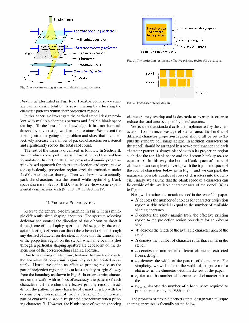
Fig. 2. A e-beam writing system with three shaping apertures.
sharing as illustrated in Fig. 1(c). Flexible blank space shar-ing can maximize total blank space sharing by relocating thecharacter patterns within their projection regions.
In this paper, we investigate the packed stencil design prob-lem with multiple shaping apertures and flexible blank spacesharing. To the best of our knowledge, it has not been ad-dressed by any existing work in the literature. We present thefirst algorithm targeting this problem and show that it can ef-fectively increase the number of packed characters on a stenciland significantly reduce the total shot count.
The rest of the paper is organized as follows. In Section II,we introduce some preliminary information and the problemformulation. In Section III.C, we present a dynamic program-ming based approach for character selection and aperture size(or equivalently, projection region size) determination underflexible blank space sharing. Then we show how to actuallypack the characters into the stencil while optimizing blankspace sharing in Section III.D. Finally, we show some experi-mental comparisons with [9] and [10] in Section IV.
II. PROBLEM FORMULATION
Refer to the general e-beam machine in Fig. 2, it has multi-ple differently sized shaping apertures. The aperture selectingdeflector can control the direction of the e-beam to shoot itthrough one of the shaping apertures. Subsequently, the char-acter selecting deflector can direct the e-beam to shoot throughany desired character on the stencil. Note that the dimensionsof the projection region on the stencil when an e-beam is shotthrough a particular shaping aperture are dependent on the di-mensions of the corresponding shaping aperture.
Due to scattering of electrons, features that are too close tothe boundary of projection region may not be printed accu-rately. Hence, we define an effective printing region as thepart of projection region that is at least a safety margin S awayfrom the boundary as shown in Fig. 3. In order to print charac-ters on the wafer with no loss of accuracy, the pattern of eachcharacter must lie within the effective printing region. In ad-dition, the pattern of any character A cannot overlap with thee-beam projection region of another character B. Otherwise,part of character A would be printed erroneously when print-ing character B. However, the blank space of two neighboring
Fig. 3. The projection region and effective printing region for a character.
Fig. 4. Row-based stencil design.
characters may overlap and is desirable to overlap in order toreduce the total area occupied by the characters.
We assume that standard cells are implemented by the char-acters. To minimize wastage of stencil area, the heights ofdifferent character projection regions should all be set to 2Splus the standard cell image height. In addition, characters onthe stencil should be arranged in a row-based manner and eachcharacter pattern is always placed within its projection regionsuch that the top blank space and the bottom blank space areequal to S. In this way, the bottom blank space of a row ofcharacters can completely overlap with the top blank space ofthe row of characters below as in Fig. 4 and we can pack themaximum possible number of rows of characters into the sten-cil. Finally, we assume that the blank space of a character canlie outside of the available character area of the stencil [8] asin Fig. 4.
Next, we introduce the notations used in the rest of the paper.• K denotes the number of choices for character projection
region widths which is equal to the number of availableshaping apertures.
• S denotes the safety margin from the effective printingregion to the projection region boundary for an e-beamshot.
• W denotes the width of the available character area of thestencil.
• R denotes the number of character rows that can fit in thestencil.
• n denotes the number of different characters extractedfrom a design.
• wc denotes the width of the pattern of character c. Forsimplicity, we will refer to the width of the pattern of acharacter as the character width in the rest of the paper.
• rc denotes the number of occurrence of character c in adie.
• nV SBcdenotes the number of e-beam shots required to
print character c by the VSB method.
The problem of flexible packed stencil design with multipleshaping apertures is formally stated below.

Def 1. Suppose the values of K, S, W , and R for an e-beammachine with multiple shaping apertures are given. A set ofn characters extracted from a design and the values of wc, rc,and nV SBc
for each character c are also given. (i) DetermineK different character projection region widths, (ii) select thecharacters to be put on the stencil, and (iii) pack the characterson the stencil in a row-based manner with flexible blank spacesharing to minimize the total shot count for the design underthe following constraints.(C1) The pattern of each character must lie within the effectiveprinting region of the character.(C2) The pattern of each character cannot lie within the pro-jection region of any other character.(C3) The patterns of all characters must lie within the avail-able character area of the stencil.
Lemma 1. The flexible packed stencil design problem is NP-complete.
It can be shown that the 0-1 knapsack problem, which is awell-known NP-complete problem [12], can be reduced to thesubproblem of selecting and packing of n characters on a sten-cil in which n character projection region widths are allowed.So the flexible packed stencil design problem is NP-complete.
III. ALGORITHM
III.A. Algorithm Outline
As the problem is very complicated, we break it down intothree steps. First, we propose a dynamic programming algo-rithm to determine K projection region widths and to select aset of most beneficial characters that roughly can be packed onthe stencil. Then we distribute the selected characters to dif-ferent rows and construct tight linear packing for each row. Atlast, we greedily refine the solution by checking if any of theunselected characters can be added to the end of the tight linearpacking of some row. The outline of the algorithm is given inAlgorithm 1.
Algorithm 1 Flexible Packed Stencil Design1: Determine K projection region widths and select a set of
characters to be put on the stencil by dynamic program-ming.
2: Assign the characters selected in Step 1 to rows on thestencil and construct tight linear packing for each row.
3: Greedily pack some of the unselected characters at the endof each row, if possible.
Our algorithm is based on the key concepts of tight linearpacking and effective character width. So, we will first intro-duce them in Section III.B. Then, we will describe the detailsof Step 1 of Algorithm 1 in Section III.C and the details ofSteps 2 and 3 in Section III.D.
III.B. Tight Linear Packing and Effective Character Width
We introduce some definitions related to our problem.
Def 2. A linear packing of a group of characters is a packingof all the given characters in a row with flexible blank spacesharing satisfying constraints (C1) and (C2).
Fig. 5. A tight linear packing. Characters with even indexes are shifted downa bit to show the projection regions of all characters more clearly.
Def 3. The width of a linear packing is the total span of thepacking excluding the left blank space of the first characterand the right blank space of the last character. (See Fig. 5.)
In the following discussion, we assume that the charactersin a linear packing are indexed from left to right by 1, 2, 3, . . ..And the width of the projection region for character i is de-noted by Ei.
Def 4. A tight linear packing is a linear packing such that forany two neighboring characters i and i + 1, the right blankspace of character i and the left blank space of character i+1are exactly equal and completely overlap.
For example, Fig. 5 shows a tight linear packing of six char-acters.
Def 5. The effective width of a character c is defined as (wc +Ec)/2.
Below we show that the width of any tight linear packing isapproximately equal to the total effective width of its charac-ters.
Lemma 2. For a linear packing P of k characters, let W (P )denote the width of P , wi(P ) denote the width of the i-th char-acter (i = 1, 2, . . . , k), s0(P ) denote the width of the left blankspace of the first character, and sk(P ) denote width of the rightblank space of the last character in P .For a tight linear packing Pt,
W (Pt) =k∑
i=1
(wi(Pt) + Ei)/2− s0(Pt)/2− sk(Pt)/2
For an arbitrary linear packing Pa,
W (Pa) ≥k∑
i=1
(wi(Pa) + Ei)/2− s0(Pa)/2− sk(Pa)/2
Proof. For a tight linear packing Pt, the right blank space ofthe i-th character and the left blank space of the (i + 1)-thcharacter are exactly equal and completely overlap for i =1, 2, . . . , k − 1. So, its width can be expressed as W (Pt) =∑k
i=1 wi(Pt) +∑k−1
i=1 si(Pt) where si(Pt) denote the widthof the right blank space of the i-th character in Pt.
For each character i in Pt, we have si−1(Pt) + wi(Pt) +si(Pt) = Ei since its left and right blank spaces are equal tosi−1(Pt) and si(Pt), respectively. Hence,
∑ki=1(si−1(Pt) +
wi(Pt) + si(Pt)) =∑k
i=1Ei. It implies that 2 ×∑k−1i=1 si(Pt) =
∑ki=1Ei −
∑ki=1 wi(Pt)− s0(Pt)− sk(Pt).

So, the width of a tight linear packing Pt can be re-written as
W (Pt) =k∑
i=1
wi(Pt)/2 + (k∑
i=1
Ei − s0(Pt)− sk(Pt))/2
=k∑
i=1
(wi(Pt) + Ei)/2− s0(Pt)/2− sk(Pt)/2.
For an arbitrary linear packing Pa, we let gi(Pa) be thewidth of the gap between the i-th and (i + 1)-th characterpatterns in Pa for i = 1, 2, . . . , k − 1, and let g0(Pa) bes0(Pa) and gk(Pa) be sk(Pa). Then Pa’s width can be ex-pressed as W (Pa) =
∑ki=1 wi(Pa)+
∑k−1i=1 gi(Pa). Note that
gi−1(Pa) + wi(Pa) + gi(Pa) ≥ Ei for each character i. Itimplies that 2×
∑k−1i=1 gi(Pa) ≥
∑ki=1Ei −
∑ki=1 wi(Pa)−
s0(Pa)− sk(Pa). So,
W (Pa) ≥k∑
i=1
(wi(Pa) + Ei)/2− s0(Pa)/2− sk(Pa)/2.
By applying Lemma 2, we can derive an upper bound of thedifference between the width of a tight linear packing and thewidth of the minimum width linear packing and get Lemma 3.
Lemma 3. Given a group of k characters, the width of anytight linear packing is less than (E1 +Ek)/2− 2S away fromthe minimum width linear packing.
It is apparent that if we can construct a tight linear packing,it will be a near optimal linear packing. As we will show inSection III.D, there is an efficient way to compute tight linearpacking.
III.C. Projection Region Width and Character Selection by DP
In Step 1 of Algorithm 1, in order to determine the projec-tion region widths and characters to be put into the stencil, wemerge all rows of the stencil into a single row and use dynamicprogramming to maximize the overall shot saving subject to atotal effective character width constraint.
Assume the characters are sorted in increasing order ofwidth. We define S[e, i, k, w] as the maximum shot savingusing at most k different projection region widths for print-ing a subset of the first i characters such that the largestprojection region width is e and the total effective width ofthe subset is at most w. The ranges of the parameters arew1 + 2S ≤ e ≤ wn + 2S, 0 ≤ i ≤ n, 1 ≤ k ≤ K, and0 ≤ w ≤ RW .S[e, i, k, w] can be expressed recursively as follow:
S[e, 0, k, w] = 0 for all e, k, wS[e, i, k, 0] = 0 for all e, i, kS[e, i, k, w]
= max
S[e, i− 1, k, w]ri(nV SBi− 1) + S[e, i− 1, k, w − wi+e
2 ]if (wi + 2S ≤ e and wi+e
2 ≤ w)0 otherwise{S[wi + 2S, i, k − 1, w] if k > 10 otherwise
for all e, i 6= 0, k, w 6= 0
In the recursive expression above, S[e, i, k, w] is the maxi-mum over three cases. In the first case, character i is skipped.In the second case, character i is selected. It results in a shotsaving of ri(nV SBi
− 1) and a reduction of remaining effec-tive width by wi+e
2 . In the third case, another projection regionwidth of wi + 2S is used.
Then the maximum shot saving is given bymaxi {S[wi + 2S, i,K,RW ]}. It is clear that the aboverecursion to compute the values of S[e, i, k, w] for all e, i, k, wcan be implemented as a dynamic program. However, as wewill see in Section 4, the memory requirement for typicalproblem instances can be up to tens of gigabytes. In otherwords, this dynamic programming formulation is not practical.
In order to reduce the memory requirement, we take advan-tage of the fact that many characters have the same width. In-stead of considering each character separately, we group char-acters of the same width together. Let Gj be the group of char-acters of width wj . Assume that the characters within eachgroup are sorted in decreasing order of shot saving.
We define S′[e, j, k, w] as the maximum shot saving usingat most k different projection region widths for printing somesubset of characters in each of the first j groups such that thelargest projection region width is e and the total effective widthof the subset is at most w.S′[e, j, k, w] can be expressed recursively as follow:
S′[e, 0, k, w] = 0 for all e, k, wS′[e, j, k, 0] = 0 for all e, j, kS′[e, j, k, w]
= max
S′[e, j − 1, k, w]maxi∈{1,2,...,|Gj |}R(e, j, k, w, i){S′[wj + 2S, j, k − 1, w] if k > 10 otherwise
for all e, j 6= 0, k, w 6= 0
where R(e, j, k, w, i) is the shot saving if the first i charactersin Gj (i.e., the i highest shot saving characters in Gj) are in-cluded in the stencil. Let Gj [i] be the set of first i characters inGj . ThenR(e, j, k, w, i) is given by the following expression:
R(e, j, k, w, i)
=
∑
c∈Gj [i]
rc(nV SBc− 1) + S′[e, j − 1, k, w − i× wj + e
2]
if wj + 2S ≤ e and i× wj+e2 ≤ w
0 otherwise
The three cases for S′[e, j, k, w] are similar to those forS[e, i, k, w] except that a set of i characters in Gj is selectedinstead of a single character in the second case. As the num-ber of groups are typically at least tens of times less than thenumber of characters, the memory requirement to computeS′[e, j, k, w] would be reduced to less than 1 gigabyte in prac-tice as shown in Section 4. Note that this group-based dynamicprogram and the character-based dynamic program above gen-erate identical solutions and have the same runtime complex-ity. The only difference is that the group-based approach usesmuch less memory.
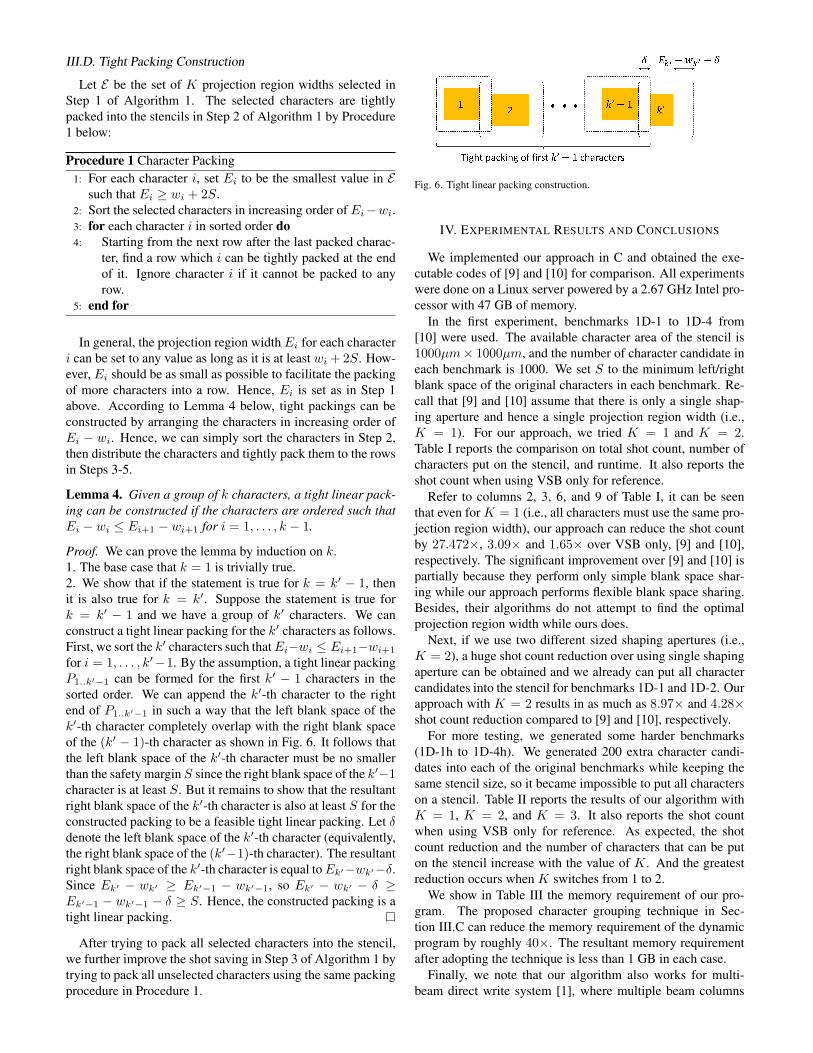
III.D. Tight Packing Construction
Let E be the set of K projection region widths selected inStep 1 of Algorithm 1. The selected characters are tightlypacked into the stencils in Step 2 of Algorithm 1 by Procedure1 below:
Procedure 1 Character Packing1: For each character i, set Ei to be the smallest value in E
such that Ei ≥ wi + 2S.2: Sort the selected characters in increasing order of Ei−wi.3: for each character i in sorted order do4: Starting from the next row after the last packed charac-
ter, find a row which i can be tightly packed at the endof it. Ignore character i if it cannot be packed to anyrow.
5: end for
In general, the projection region width Ei for each characteri can be set to any value as long as it is at least wi + 2S. How-ever, Ei should be as small as possible to facilitate the packingof more characters into a row. Hence, Ei is set as in Step 1above. According to Lemma 4 below, tight packings can beconstructed by arranging the characters in increasing order ofEi − wi. Hence, we can simply sort the characters in Step 2,then distribute the characters and tightly pack them to the rowsin Steps 3-5.
Lemma 4. Given a group of k characters, a tight linear pack-ing can be constructed if the characters are ordered such thatEi − wi ≤ Ei+1 − wi+1 for i = 1, . . . , k − 1.
Proof. We can prove the lemma by induction on k.1. The base case that k = 1 is trivially true.2. We show that if the statement is true for k = k′ − 1, thenit is also true for k = k′. Suppose the statement is true fork = k′ − 1 and we have a group of k′ characters. We canconstruct a tight linear packing for the k′ characters as follows.First, we sort the k′ characters such thatEi−wi ≤ Ei+1−wi+1
for i = 1, . . . , k′−1. By the assumption, a tight linear packingP1..k′−1 can be formed for the first k′ − 1 characters in thesorted order. We can append the k′-th character to the rightend of P1..k′−1 in such a way that the left blank space of thek′-th character completely overlap with the right blank spaceof the (k′ − 1)-th character as shown in Fig. 6. It follows thatthe left blank space of the k′-th character must be no smallerthan the safety margin S since the right blank space of the k′−1character is at least S. But it remains to show that the resultantright blank space of the k′-th character is also at least S for theconstructed packing to be a feasible tight linear packing. Let δdenote the left blank space of the k′-th character (equivalently,the right blank space of the (k′−1)-th character). The resultantright blank space of the k′-th character is equal toEk′−wk′−δ.Since Ek′ − wk′ ≥ Ek′−1 − wk′−1, so Ek′ − wk′ − δ ≥Ek′−1 − wk′−1 − δ ≥ S. Hence, the constructed packing is atight linear packing.
After trying to pack all selected characters into the stencil,we further improve the shot saving in Step 3 of Algorithm 1 bytrying to pack all unselected characters using the same packingprocedure in Procedure 1.
Fig. 6. Tight linear packing construction.
IV. EXPERIMENTAL RESULTS AND CONCLUSIONS
We implemented our approach in C and obtained the exe-cutable codes of [9] and [10] for comparison. All experimentswere done on a Linux server powered by a 2.67 GHz Intel pro-cessor with 47 GB of memory.
In the first experiment, benchmarks 1D-1 to 1D-4 from[10] were used. The available character area of the stencil is1000µm× 1000µm, and the number of character candidate ineach benchmark is 1000. We set S to the minimum left/rightblank space of the original characters in each benchmark. Re-call that [9] and [10] assume that there is only a single shap-ing aperture and hence a single projection region width (i.e.,K = 1). For our approach, we tried K = 1 and K = 2.Table I reports the comparison on total shot count, number ofcharacters put on the stencil, and runtime. It also reports theshot count when using VSB only for reference.
Refer to columns 2, 3, 6, and 9 of Table I, it can be seenthat even for K = 1 (i.e., all characters must use the same pro-jection region width), our approach can reduce the shot countby 27.472×, 3.09× and 1.65× over VSB only, [9] and [10],respectively. The significant improvement over [9] and [10] ispartially because they perform only simple blank space shar-ing while our approach performs flexible blank space sharing.Besides, their algorithms do not attempt to find the optimalprojection region width while ours does.
Next, if we use two different sized shaping apertures (i.e.,K = 2), a huge shot count reduction over using single shapingaperture can be obtained and we already can put all charactercandidates into the stencil for benchmarks 1D-1 and 1D-2. Ourapproach with K = 2 results in as much as 8.97× and 4.28×shot count reduction compared to [9] and [10], respectively.
For more testing, we generated some harder benchmarks(1D-1h to 1D-4h). We generated 200 extra character candi-dates into each of the original benchmarks while keeping thesame stencil size, so it became impossible to put all characterson a stencil. Table II reports the results of our algorithm withK = 1, K = 2, and K = 3. It also reports the shot countwhen using VSB only for reference. As expected, the shotcount reduction and the number of characters that can be puton the stencil increase with the value of K. And the greatestreduction occurs when K switches from 1 to 2.
We show in Table III the memory requirement of our pro-gram. The proposed character grouping technique in Sec-tion III.C can reduce the memory requirement of the dynamicprogram by roughly 40×. The resultant memory requirementafter adopting the technique is less than 1 GB in each case.
Finally, we note that our algorithm also works for multi-beam direct write system [1], where multiple beam columns

TABLE ICOMPARISON WITH [9] AND [10].
VSB only [9] [10] Ours (K = 1) Ours (K = 2)
#shots #shots #ch CPU(s) #shots #ch CPU(s) #shots #ch CPU(s) #shots #ch CPU(s)
1D-1 770543 50809 926 12.13 29536 934 1.91 12972 980 6.90 10418 1000 22.21
1D-2 770543 93465 854 10.24 44544 863 1.74 28594 895 6.41 10418 1000 20.73
1D-3 770543 152376 749 7.85 78704 758 2.35 55761 797 6.59 30785 902 21.13
1D-4 770543 193494 687 6.52 107460 699 2.96 79275 734 7.47 44468 837 29.07
Normalized 27.472 3.090 0.944 1.355 1.650 0.955 0.325 1.000 1.000 1.000 0.570 1.102 3.388
TABLE IIRESULTS ON HARDER BENCHMARKS BY OUR ALGORITHMS FOR DIFFERENT VALUES OF K .
VSB only Ours (K = 1) Ours (K = 2) Ours (K = 3)
#shots #shots #ch CPU(s) #shots #ch CPU(s) #shots #ch CPU(s)
1D-1h 922770 58648 980 8.82 26467 1114 27.22 17534 1163 43.33
1D-2h 922770 86176 905 8.43 48891 1018 25.58 39630 1068 40.67
1D-3h 922770 135332 800 8.63 93109 916 25.69 75709 948 40.89
1D-4h 922770 169105 739 9.76 116219 855 27.02 98204 886 42.91
Normalized 9.680 1.000 1.000 1.000 0.598 1.141 2.966 0.475 1.188 4.718
TABLE IIIMEMORY USAGE (GB) WITH AND WITHOUT USING THE MEMORY SAVING
TECHNIQUE.
With memory saving Without memory saving
K = 1 K = 2 K = 3 K = 1 K = 2 K = 3
1D-1 0.136 0.271 0.407 5.236 10.436 15.670
1D-2 0.131 0.262 0.392 5.044 10.087 15.092
1D-3 0.141 0.282 0.422 5.041 10.082 15.087
1D-4 0.156 0.311 0.467 5.205 10.377 15.582
1D-1h 0.136 0.271 0.407 6.282 12.564 18.800
1D-2h 0.131 0.262 0.392 6.051 12.102 18.154
1D-3h 0.141 0.282 0.422 6.048 12.096 18.144
1D-4h 0.156 0.311 0.467 6.245 12.490 18.696
furnished with their own stencils write different regions of awafer in parallel. As identical dies are typically manufacturedon a wafer, the stencil design for all beam columns in a multi-beam system should be the same and is not different from asingle beam system.
REFERENCES
[1] T. Maruyama, Y. Machida, and S. Sugatani. CP based EBDWthroughput enhancement for 22nm high volume manufacturing.In Proceedings of SPIE 7637, February 2010. 7637-1S.
[2] T. Maruyama et al. CP element based design for 14nm nodeEBDW high volume manufacturing. In Proceedings of SPIE8323, April 2012. 8323-14.
[3] B. J. Lin. Future of multiple-E-beam direct-write systems. InProceedings of SPIE 8323, March 2012.
[4] R. Inanami et al. Maskless lithography: Estimation of thenumber of shots for each layer in a logic device with charac-ter projection-type low-energy electron-beam direct writing sys-tem. In Proceedings of SPIE 5037, pages 1043–1050, 2003.
[5] H. Pfeiffer. Variable spot shaping for electron-beam lithography.Journal of Vaccum Sci. and Tech., 15(3):887–890, May 1978.
[6] M. Sugihara et al. A character size optimization technique forthroughput enhancement of character projection lithography. InProc. of ISCAS, pages 2561–2564, 2006.
[7] A. Fujimura. Design for E-beam: Design insights for direct-write maskless lithography. In Proceedings of SPIE 7823, pages137–140, Sep. 2010.
[8] K. Yoshida et al. Stencil design and method for improving char-acter density for cell projection charged particle beam lithogra-phy. US Patent Application No. 2009/0325085 A1, December2009.
[9] K. Yuan, B. Yu, and D. Z. Pan. E-beam lithography stencil plan-ning and optimization with overlapped characters. IEEE Trans.on Computer-Aided Design of Integrated Circuits and Systems,31(2):167–179, Feb 2012.
[10] B. Yu, K. Yuan, J.-R. Gao, and D.Z. Pan. E-BLOW: e-beamlithography overlapping aware stencil planning for MCC sys-tem. In Proc. of DAC, 2013.
[11] R. Inanami. Electron beam exposure apparatus, electron beamexposure method and method of manufacturing semiconductordevice. US Patent No. 7449700, November 2008.
[12] M. R. Garey and D. S. Johnson. Computers and Intractability: AGuide to the Theory of NP-Completeness. Freeman, NY, 1979.


