Embed Size (px)
Citation preview

A L T R A I N D U S T R I A L M O T I O N
Lamiflex Couplings+55 11 5679 6553+55 11 5679 7735
Flexible Disc Couplings TB Wood’s Form-Flex® & Torsiflex-i

Table of ContentsIntroduction
Product Features and Options ........................................... Page 1
Disc Coupling Advantages ................................................. Page 1
Typical Applications ........................................................... Page 1
Coupling Application Types ................................................ Page 2
Coupling Selection Process ............................................... Page 3
Coupling Selection Guide .................................................. Page 4
Standard Bore Tolerances ................................................. Page 5
Industry Standard Reference ............................................. Page 6
Dynamic Balance Recommendations ................................ Page 6
Disc Coupling Misalignment Discussion ............................. Page 6
Product Differentiation ....................................................... Page 7
Spacer CouplingsAP Series - Form-Flex® ...................................................... Page 9GP Series - Form-Flex® ..................................................... Page 10, 11TFI Series - Torsiflex-i - API610 .......................................... Page 12, 13TFI Series - Torsiflex-i - API610 with Torsi-Lock .................. Page 14, 15
Floating Shaft CouplingsA5 Series - Form-Flex® ...................................................... Page 17G5 Series - Form-Flex® ...................................................... Page 18, 19A5C Series (Composite) - Form-Flex® ................................ Page 20, 21
Closed Coupled CouplingsAX Series - Form-Flex® ..................................................... Page 23AA Series - Form-Flex® ..................................................... Page 24AY Series - Form-Flex® ..................................................... Page 25
Single Flex CouplingsAR Series - Form-Flex® ...................................................... Page 27GR Series - Form-Flex® ..................................................... Page 28, 29
Heavy Duty Spacer CouplingsGCH Series - Form-Flex® ................................................... Page 31GCF Series - Form-Flex® .................................................. Page 32HSH Series - Form-Flex® ................................................... Page 33FSH Series - Form-Flex® .................................................... Page 34
Coupling Repair Parts and Kits .......................................... Page 36, 37
Hub Options ...................................................................... Page 38, 39
Design Options .................................................................. Page 40, 41
Bolt Thread Size ................................................................ Page 42
Bolt/Nut Tightening Torque ................................................ Page 42
Application Data Sheet ...................................................... Page 43, 44

1P-7526-CG 3/14..... Altra Couplings Group 888-449-9439
Product Features and Options
Form-Flex®
FeaturesA-Series G-Series Torsiflex-i
AR, AP AX, AY, AA A5, A6, A7 GP G5 GR GCH, GCF,
HSH, FSH TFI
Standard Bore Fit: Clearance Interference
Set Screws: Standard Optional
Puller Holes: Optional Standard
Standard Flex Disc: 300 Series Stainless Steel (1) Alloy Steel (2) 300 Series SS
Balance Class: AGMA 7 N/A AGMA 8 N/A AGMA 8 N/A AGMA 9
Dynamic Balance: Optional
Per TBW Commercial
StandardOptional
Per TBW Commercial
StandardOptional N/A Optional
(1) Stainless Steel is standard. Alloy Steel is optional. (2) Alloy Steel is standard. Stainless Steel is optional.
Form-Flex® Disc Coupling Advantages• Over 40 years experience in flexible disc couplings• All metal Construction• No Lubrication• No Moving Parts• Long Life• High Torsional Stiffness• Precise Positioning - Zero Backlash
ApplicationsFlexible Disc couplings can be used in a wide variety of application from general industrial equipment to high speed precision machines. They are one of the most versatile coupling designs and can be customized to meet the demands of almost every application. Some of the applications in which Flexible Disc couplings can be used are:
• General Purpose & API610 Pumps• Centrifugal & Screw Compressors• Reciprocating Compressors• Fans & Blowers• Food Processing• Machine Tools• Cooling towers• Printing Presses• Engine & Electric Motor Driven Applications• Power Generation
2 Altra Couplings Group 888-449-9439 .....P-7526-CG 3/14
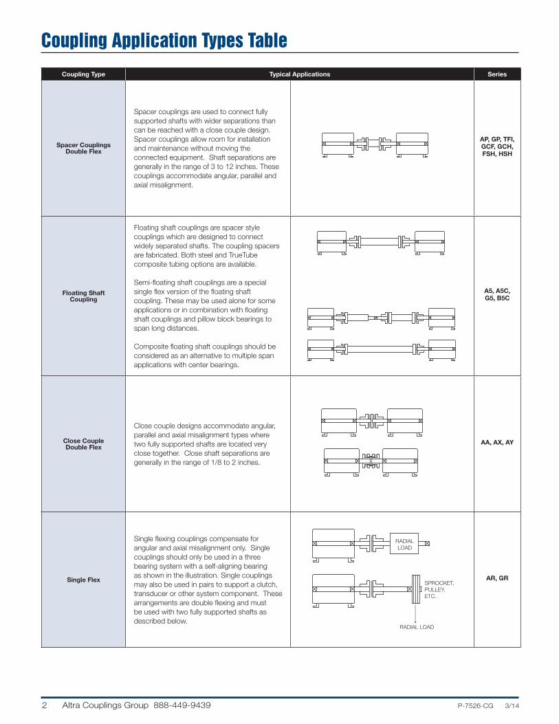
Coupling Application Types Table
Coupling Type Typical Applications Series
Spacer Couplings Double Flex
Spacer couplings are used to connect fully supported shafts with wider separations than can be reached with a close couple design. Spacer couplings allow room for installation and maintenance without moving the connected equipment. Shaft separations are generally in the range of 3 to 12 inches. These couplings accommodate angular, parallel and axial misalignment.
RADIALLOAD
SPROCKET,PULLEY,ETC.
RADIAL LOAD
AP, GP, TFI, GCF, GCH, FSH, HSH
Floating Shaft Coupling
Floating shaft couplings are spacer style couplings which are designed to connect widely separated shafts. The coupling spacers are fabricated. Both steel and TrueTube composite tubing options are available.
Semi-floating shaft couplings are a special single flex version of the floating shaft coupling. These may be used alone for some applications or in combination with floating shaft couplings and pillow block bearings to span long distances.
Composite floating shaft couplings should be considered as an alternative to multiple span applications with center bearings.
RADIALLOAD
SPROCKET,PULLEY,ETC.
RADIAL LOAD
A5, A5C, G5, B5C
Close Couple Double Flex
Close couple designs accommodate angular, parallel and axial misalignment types where two fully supported shafts are located very close together. Close shaft separations are generally in the range of 1/8 to 2 inches.
RADIALLOAD
SPROCKET,PULLEY,ETC.
RADIAL LOAD
AA, AX, AY
Single Flex
Single flexing couplings compensate for angular and axial misalignment only. Single couplings should only be used in a three bearing system with a self-aligning bearing as shown in the illustration. Single couplings may also be used in pairs to support a clutch, transducer or other system component. These arrangements are double flexing and must be used with two fully supported shafts as described below.
RADIALLOAD
SPROCKET,PULLEY,ETC.
RADIAL LOAD
AR, GR
3P-7526-CG 3/14..... Altra Couplings Group 888-449-9439
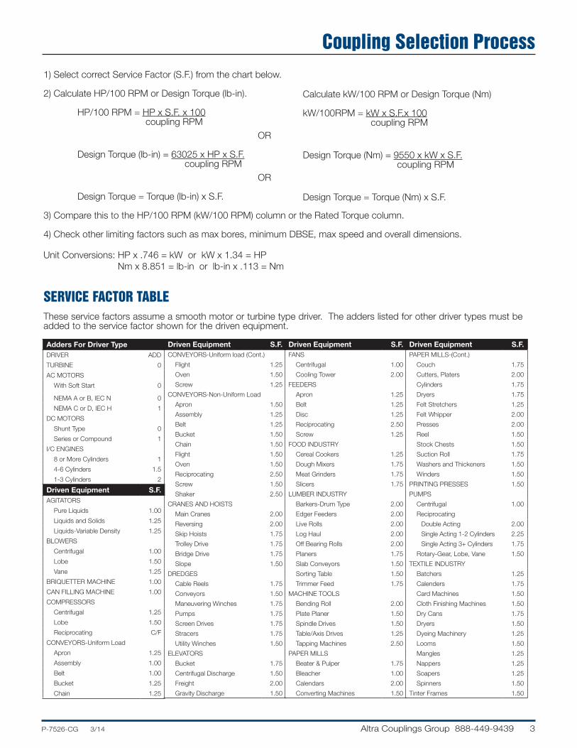
Coupling Selection Process1) Select correct Service Factor (S.F.) from the chart below.
2) Calculate HP/100 RPM or Design Torque (lb-in).
HP/100 RPM = HP x S.F. x 100 coupling RPM OR Design Torque (lb-in) = 63025 x HP x S.F. coupling RPM OR
Design Torque = Torque (lb-in) x S.F.
3) Compare this to the HP/100 RPM (kW/100 RPM) column or the Rated Torque column.
4) Check other limiting factors such as max bores, minimum DBSE, max speed and overall dimensions.
Unit Conversions: HP x .746 = kW or kW x 1.34 = HP Nm x 8.851 = lb-in or lb-in x .113 = Nm
SERVICE FACTOR TABLEThese service factors assume a smooth motor or turbine type driver. The adders listed for other driver types must be added to the service factor shown for the driven equipment.
Adders For Driver TypeDRIVER ADD
TURBINE 0
AC MOTORS
With Soft Start 0
NEMA A or B, IEC N 0
NEMA C or D, IEC H 1
DC MOTORS
Shunt Type 0
Series or Compound 1
I/C ENGINES
8 or More Cylinders 1
4-6 Cylinders 1.5
1-3 Cylinders 2
Driven Equipment S.F.AGITATORS
Pure Liquids 1.00
Liquids and Solids 1.25
Liquids-Variable Density 1.25
BLOWERS
Centrifugal 1.00
Lobe 1.50
Vane 1.25
BRIQUETTER MACHINE 1.00
CAN FILLING MACHINE 1.00
COMPRESSORS
Centrifugal 1.25
Lobe 1.50
Reciprocating C/F
CONVEYORS-Uniform Load
Apron 1.25
Assembly 1.00
Belt 1.00
Bucket 1.25
Chain 1.25
Driven Equipment S.F.CONVEYORS-Uniform load (Cont.)
Flight 1.25
Oven 1.50
Screw 1.25
CONVEYORS-Non-Uniform Load
Apron 1.50
Assembly 1.25
Belt 1.25
Bucket 1.50
Chain 1.50
Flight 1.50
Oven 1.50
Reciprocating 2.50
Screw 1.50
Shaker 2.50
CRANES AND HOISTS
Main Cranes 2.00
Reversing 2.00
Skip Hoists 1.75
Trolley Drive 1.75
Bridge Drive 1.75
Slope 1.50
DREDGES
Cable Reels 1.75
Conveyors 1.50
Maneuvering Winches 1.75
Pumps 1.75
Screen Drives 1.75
Stracers 1.75
Utility Winches 1.50
ELEVATORS
Bucket 1.75
Centrifugal Discharge 1.50
Freight 2.00
Gravity Discharge 1.50
Driven Equipment S.F.FANS
Centrifugal 1.00
Cooling Tower 2.00
FEEDERS
Apron 1.25
Belt 1.25
Disc 1.25
Reciprocating 2.50
Screw 1.25
FOOD INDUSTRY
Cereal Cookers 1.25
Dough Mixers 1.75
Meat Grinders 1.75
Slicers 1.75
LUMBER INDUSTRY
Barkers-Drum Type 2.00
Edger Feeders 2.00
Live Rolls 2.00
Log Haul 2.00
Off Bearing Rolls 2.00
Planers 1.75
Slab Conveyors 1.50
Sorting Table 1.50
Trimmer Feed 1.75
MACHINE TOOLS
Bending Roll 2.00
Plate Planer 1.50
Spindle Drives 1.50
Table/Axis Drives 1.25
Tapping Machines 2.50
PAPER MILLS
Beater & Pulper 1.75
Bleacher 1.00
Calendars 2.00
Converting Machines 1.50
Driven Equipment S.F.PAPER MILLS-(Cont.)
Couch 1.75
Cutters, Platers 2.00
Cylinders 1.75
Dryers 1.75
Felt Stretchers 1.25
Felt Whipper 2.00
Presses 2.00
Reel 1.50
Stock Chests 1.50
Suction Roll 1.75
Washers and Thickeners 1.50
Winders 1.50
PRINTING PRESSES 1.50
PUMPS
Centrifugal 1.00
Reciprocating
Double Acting 2.00
Single Acting 1-2 Cylinders 2.25
Single Acting 3+ Cylinders 1.75
Rotary-Gear, Lobe, Vane 1.50
TEXTILE INDUSTRY
Batchers 1.25
Calenders 1.75
Card Machines 1.50
Cloth Finishing Machines 1.50
Dry Cans 1.75
Dryers 1.50
Dyeing Machinery 1.25
Looms 1.50
Mangles 1.25
Nappers 1.25
Soapers 1.25
Spinners 1.50
Tinter Frames 1.50
Calculate kW/100 RPM or Design Torque (Nm)
kW/100RPM = kW x S.F.x 100 coupling RPM
Design Torque (Nm) = 9550 x kW x S.F. coupling RPM
Design Torque = Torque (Nm) x S.F.

4 Altra Couplings Group 888-449-9439 .....P-7526-CG 3/14
Coupling Selection Guide
1) Consult factory for applications in shaded areas.
2) Torque ratings may vary by coupling series.
3) Use the 1.0 service factor column if a service factor was used in the HP/100 RPM calculation.
Typical Application Conditions
SMOOTHMOTOR ORTURBINEDRIVEN
STEADYMOTOR ORTURBINEDRIVEN
MODERATEMOTOR ORTURBINEDRIVEN
MEDIUMMOTOR ORTURBINEDRIVEN
HEAVY-HIGHTQ. MOTOROR ENGINEDRIVEN
EXTRAHEAVYENGINEDRIVEN
EXTREMELYHEAVYENGINEDRIVEN
SOFTSTARTWITHSTEADYLOAD
AVERAGESTARTINGLOADS ANDSLIGHTTORQUEVARIATIONS
ABOVEAVERAGESTARTINGLOADS ANDMODERATELOADVARIATIONS
HIGHSTARTINGTORQUESANDMEDIUM TOHEAVYLOADVARIATIONS
MILD SHOCKLOADINGENGINES.DRIVINGSMOOTHLOADS.EXTREMERELIABILITY
HEAVYSHOCKLOADINGOR LIGHTREVERSING
EXTREMESHOCKLOADING.FREQUENTWIDETORQUEVARIATIONS
Type/Size
Torque RatingO.D.(in)
Service Factor
# of BoltsHP /100 RPM
Max Continuous
(lb-in)
Peak Overload
(lb-in)
Rated HP/100 RPM at Service Factor Shown
1.0 1.5 2.0 2.5 3.0 3.25 4.0
Form-Flex®
A-Series
05 0.48 300 600 2.65 0.48 0.32 0.24 0.19
4
10 1.27 800 1,600 3.19 1.27 0.85 0.63 0.51
15 2.50 1,575 3,150 3.65 2.50 1.67 1.25 1.00
20 3.49 2,200 4,400 4.08 3.49 2.33 1.75 1.40
25 6.03 3,800 7,600 4.95 6.03 4.02 3.01 2.41
30 11.00 6,930 13,860 5.63 11.00 7.33 5.50 4.40
35 18.00 11,340 22,680 6.63 17.99 12.00 9.00 7.20
Form-Flex® G-Series
311 17.5 11,000 22,000 5.88 17.45 11.64 8.73 6.98 5.8 5.4
6
321 32.5 20,500 41,000 6.38 32.53 21.68 16.3 13.0 10.8 10
332 50.8 32,000 64,000 7.20 50.8 33.8 25 20 17 16
346 73.0 46,000 92,000 8.20 73.0 48.7 36 29 24 22
380 127 80,000 160,000 9.36 127 85 63 51 42 39
340 63.5 40,000 80,000 8.38 63.5 42.3 32 25 21 20 16
8
412 190 120,000 240,000 11.00 190 127 95 76 63 59 48
419 301 190,000 380,000 12.50 301 201 151 121 100 93 75
424 476 300,000 600,000 15.00 476 317 238 190 159 146 119
444 690 435,000 870,000 16.38 690 460 345 276 230 212 173
456 889 560,000 1,120,000 18.00 889 592 444 355 296 273 222
483 1317 830,000 1,660,000 19.44 1317 878 658 527 439 405 329
511 1745 1,100,000 2,200,000 22.00 1745 1164 873 698 582 537 436
520 3173 2,000,000 4,000,000 24.88 3173 2116 1587 1269 1058 976 793
525 3967 2,500,000 5,000,000 26.75 3967 2644 1983 1587 1322 1221 992
530 4760 3,000,000 6,000,000 28.00 4760 3173 2380 1904 1587 1465 1190
540 6347 4,000,000 8,000,000 33.50 6347 4231 3173 2539 2116 1953 1587
Torsiflex-iTFI
17 2.4 1,504 2,632 2.87 2.39 1.59 1.19 0.95 0.80 0.73
6
27 3.8 2,390 4,183 3.35 3.79 2.53 1.90 1.52 1.26 1.17
38 5.3 3,363 5,885 4.21 5.34 3.56 2.67 2.13 1.78 1.64
140 19.7 12,391 21,684 5.00 19.66 13.1 9.83 7.86 6.6 6.0
260 36.5 23,031 40,304 6.06 36.54 24 18.3 14.6 12 11
400 56.2 35,404 61,957 6.93 56.2 37 28 22 19 17
750 105 66,383 116,170 7.99 105 70 53 42 35 32
1310 184 115,948 202,909 9.49 184 123 92 74 61 57
1900 267 168,169 294,296 10.98 267 178 133 107 89 82
8
2500 351 221,275 387,231 11.65 351 234 176 140 117 108
3300 463 292,083 511,145 12.84 463 309 232 185 154 143
6000 843 531,060 929,355 15.55 843 562 421 337 281 259
8500 1194 752,335 1,316,586 17.44 1194 796 597 477 398 367
12000 1685 1,062,120 1,858,710 19.45 1685 1123 843 674 562 519
Form-Flex® (HSH/FSH)
22 15.1 9,500 14,250 6.00 15.07 10.05 7.54 6.03 5.02 4.64 3.8
8
26 25.4 16,000 24,000 6.87 25.39 16.9 12.7 10.2 8.5 7.8 6
31 38.1 24,000 36,000 8.12 38.08 25 19.0 15.2 13 12 10
35 69.8 44,000 66,000 9.12 69.8 47 35 28 23 21 17
37 95.2 60,000 90,000 10.06 95.2 63 48 38 32 29 24
42 116 73,000 109,500 11.00 116 77 58 46 39 36 29
45 157 99,000 148,500 11.44 157 105 79 63 52 48 39
50 203 128,000 192,000 13.00 203 135 102 81 68 62 51
55 300 189,000 283,500 15.00 300 200 150 120 100 92 75
60 414 261,000 391,500 16.00 414 276 207 166 138 127 104
70 658 415,000 622,500 18.50 658 439 329 263 219 203 165
75 846 533,000 799,500 20.00 846 564 423 338 282 260 211
80 1087 685,000 1,027,500 22.00 1087 725 543 435 362 334 272
85 1315 829,000 1,243,500 23.75 1315 877 658 526 438 405 329
92 1650 1,040,000 1,560,000 25.75 1650 1100 825 660 550 508 413
92HT 2221 1,400,000 2,100,000 25.75 2221 1481 1111 889 740 683 555
Consult Altra Couplings Engineering
Not Recommended for these Applications

5P-7526-CG 3/14..... Altra Couplings Group 888-449-9439
Standard Bore Tolerances
Metric Standard Bore and Keyway InfoRecommended Bore Tolerance for Metric Shafts (mm)
Nominal Shaft Range Shaft
Tol.Shaft Des.
Clearance Fit Clearance Fit
Over To(Incl.)
Bore Tol.
Bore Des.
Bore Tol.
Bore Des.
12 18 +.008 /-.003
j6
+.016 /+.034 F7 -.015 /
-.004 M6
19 30 +.009 /-.004
+.020 /+.041 F7 -.017 /
-.004 M6
32 50 +.018 /+.002 k6 +.025 /
+.050 F7 -.013 /+.003 K6
55 80 +.030 /+.011
m6
+.030 /+.060 F7 -.021 /
+.009 K7
85 100 +.035 / +.013
+.036 /+.071 F7
-.035 / +.000 M7
110 120 +.035 / +.013
-.059 / -.024 P7
125 180 +.040 /+.015
+.043 /+.083 F7 -.068 /
-.028 P7
190 200
+.046 /+.017
+.050 /+.096 F7
-.079 /-.033 P7
210 225 -.109 /-.063 R7
230 250 -.113 /-.067 R7
260 280 +.052 /+.020
+.056 /+.108 F7 -.126 /
-.074 R7
Nominal Bore Range Nominal
Key Size
Hub Keyway
Width Depth
Over To(Incl.) Nominal Nominal
10 12 4X4 4 1.8
12 17 5X5 5 2.3
17 22 6X6 6 2.8
22 30 8X7 8 3.3
30 38 10X8 10 3.3
38 44 12X8 12 3.3
44 50 14X9 14 3.8
50 58 16X10 16 4.3
58 65 18X11 18 4.4
65 75 20X12 20 4.9
75 85 22X14 22 5.4
85 95 25X15 25 5.4
95 110 28X16 28 6.4
110 130 32X18 32 7.4
130 150 36X20 36 8.4
150 170 40X22 40 9.4
170 200 45X25 45 10.4
200 230 50X28 50 11.4
230 260 56X32 56 12.4
260 290 63X32 63 12.4
Recommended Hub Keyway Dimensions (mm)
Reference AGMA 9112-A04Standard metric keyway width tolerance per Js9
Imperial Standard Bore and Keyway InfoRecommended Bore Tolerance for Imperial Shafts (Inches)
Nominal Shaft Range Shaft
Tol.Interference Fit
Bore Tol.Clearance Fit
Bore Tol.Over To
(Incl.)
.4375 1.5+.0000
/-.0005
-.0005 / -.0010 +.0010 / -.0000
1.5 2
+.0000 /
-.0010
-.0010 /-.0020 +.0010 / -.0000
2 3 -.0010 /-.0020
+.0015 / -.00003 4 -.0015 / -.0030
4 5 -.0020 / -.0035
5 7 -.0025 / -.0040
7 8 -.0030 / -.0050 N/A
8 9 -.0035 / -.0055 N/A
9 10 -.0040 / -.0060 N/A
Nominal Bore Range Key Dims.
Over To(Incl.) Width Depth Square
KeyDepth
Reduced Key
0.312 0.438 0.094 0.047 -
0.438 0.562 0.125 0.063 0.047
0.562 0.875 0.188 0.094 0.062
0.875 1.250 0.25 0.125 0.094
1.250 1.375 0.312 0.156 0.125
1.375 1.750 0.375 0.188 0.125
1.750 2.250 0.500 0.250 0.188
2.250 2.750 0.625 0.313 0.219
2.750 3.250 0.750 0.375 0.250
3.250 3.750 0.875 0.438 0.313
3.750 4.500 1.000 0.500 0.375
4.500 5.500 1.250 0.625 0.438
5.500 6.500 1.500 0.750 0.500
6.500 7.500 1.750 0.875 0.750
7.500 9.000 2.000 1.000 0.750
9.000 11.000 2.500 1.250 0.875
Recommended Hub Keyway Dimensions (Inches)
Reference AGMA 9002-B04
Standard keyway fit is Commercial Class per AGMA 9002-B04
IMPERIAL METRICKEYWAYWIDTH
NOMINAL KEYWAY DEPTH MEASURED AT SIDE
NOMINAL KEYWAY DEPTHMEASURED AT CENTER

6 Altra Couplings Group 888-449-9439 .....P-7526-CG 3/14
Engineering StandardsINDUSTRY STANDARDS REFERENCEDAGMA 9002-B04 - BORES AND KEYWAYS FOR FLEXIBLE COUPLINGS (INCH SERIES)AGMA 9112-A04 - BORES AND KEYWAYS FOR FLEXIBLE COUPLINGS(METRIC SERIES)AGMA 922-A96 - LOAD CLASSIFICATION AND SERVICE FACTORS FOR FLEXIBLE COUPLINGSAPI610 / ISO 13709 - CENTRIFUGAL PUMPS FOR PETROLEUM, PETROCHEMICAL AND NATURAL GAS INDUSTRY, 11th Edition - Torsiflex-i meets the requirements of API610, 11th Edition when supplied with interference fit bores.API671 / ISO 10441 - SPECIAL PURPOSE COUPLINGS FOR PETROLEUM, CHEMICAL AND GAS INDUSTRY SERVICES, 4th EditionNEMA MG1 14.38, MG1 20.81 AND MG1 21.82 - All Form-Flex® & Torsiflex-i flexible disc couplings meet these standards without the addition of a limited end float device
Certain tables and data in this catalog were extracted from the reference AGMA standards with the permission of the publisher, the American Gear Manufacturers Associations, 1901 North Meyer Drive, Arlington, VA 22209.
DYNAMIC BALANCING RECOMMENDATIONSUse this graph to determine the appropriate balance class based on coupling weight and operating speed. The balance classes listed on the graph are for equipment with average sensitivity to coupling unbalance. The user should determine how sensitive the equipment train is to coupling unbalance. Use one balance class higher if your system has higher than average sensitivity to unbalance. Use one balance class lower if your system has lower than average sensitivity to unbalance. Use this guide to check your coupling selection against the recommended balance class for your operating conditions.
The following factors should be considered when determining a machine’s sensitivity to coupling unbalance.
1) Shaft End Deflection: Machines having flexible shaft extensions are relatively sensitive to coupling unbalance.
2) Bearing Load Due to Coupling Weight Relative to Total Bearing Load: Machines having lightly loaded bearings, bearings that are primarily loaded by the weight of the coupling or other overhung weight are relatively sensitive to coupling unbalance.
3) Bearing, Bearing Support and Foundation Flexibility: Machines or systems with flexible foundations for supports for the rotating elements are relatively sensitive to coupling unbalance.
4) System Natural Frequencies: Machines operating at or near natural frequencies are sensitive to coupling unbalance.5) Machine Separation: System having widely separated machines are relatively sensitive to coupling unbalance.6) Shaft Extension Relative to Bearing Span: Machines having a short bearing span relative to their shaft extensions are
sensitive to static unbalance.
HOW FLEXIBLE DISC COUPLINGS ACCOMMODATE MISALIGNMENTDouble flexing metal disc couplings may be used to accommodate angular, parallel and axial misalignment. Single flexing couplings may only be used to accommodate angular and axial misalignment. A metal disc type coupling uses a double hinge effect through two flexible discs and the spacer to compensate for parallel offset misalignment between shafts. Parallel misalignment imposes the same angular deflection (A) on each flex disc. Angular misalignment of either connected shaft, (B), creates additional angular deflections which are added to the angular offset due to parallel misalignment. The total misalignment angle, (C), at the flex disc is equal to the angular offset due to parallel misalignment (A) plus the angular offset due to angular misalignment (B). The maximum misalignment angle (C) should never exceed the rated misalignment capacity of the coupling type being used. Machinery equipment changes in actual operation and over the life of the equipment. We recommend that the machinery misalignment be set as close to zero as possible when a coupling is installed. We recommend keeping the measured misalignment below 25% of the rated misalignment capacity of the coupling type used when the machinery is installed and aligned. The remaining coupling misalignment capacity will then be available to accommodate additional misalignment caused by foundation shifts, vibrations, thermal growth or other causes.
PARALLELOFFSET
CONSULTT.B. WOOD’S
ENGINEERING
MAXIMUM SERVICE SPEED, THOUSANDS OF RPM
1
1
2.5
5
10
25
50
100
200
500
1000
2
5
10
20
50
100
200
500
1000
2000
2 3 4 5 6 8 10 20 30 40 50
1 2 3 4 5 6 8 10 20 30 40 50
CO
UP
LIN
G N
ET
WE
IGH
T (L
BS
.)
CO
UP
LIN
G N
ET
WE
IGH
T (L
BS
.) P
ER
BA
LAN
CIN
G P
LAN
E(C
OU
PLI
NG
1/2
WE
IGH
T)
BALANCE CLASS SELECTION CHART
AGM
A CLASS 10
AGM
A CLASS 9
AGM
A CLASS 8
AGM
A CLASS 7
AGM
A CLASS 6
A
AC
B
B
A

7P-7526-CG 3/14..... Altra Couplings Group 888-449-9439
Form-Flex®
A-Series sizes 5-35Torsiflex-i
Sizes 1900-1200
Torsiflex-i Sizes 27-1310
Form-Flex® HSH/FSH
Product DifferentiationForm-Flex®
A - SeriesForm-Flex®
G - SeriesTorsiflex-i
TFI - Series
Higher bore capacity in low torque range Higher Torque Density Higher Torque Density and large bore capacity
1 ° Misalignment .3 - .5 ° Misalignment .3 - .5 ° Misalignment
Clearance Fit is standard Interference Fit is standard Interference Fit is standard
AGMA 7 balance class AGMA 8 balance class AGMA 9 balance class
Non-Unitized Flex Pack Unitized Flex Pack Factory assembled Transmission Unit
ATEX Group II/ Cat 3 ATEX Group II/ Cat 3 ATEX Group II/ Cat 2 Anti-Sparking design is standard
Low to Moderate Speeds Low to Moderate Speeds High to Moderate speeds
DISC PACK DESIGN COMPARISON
Form-Flex® G-Series Sizes 311-346
Form-Flex® G-SeriesSizes 340 & 380-511
Form-Flex® A-Series
Sizes 5-35
NON-UNITIZED• Disc pack creates a bending moment
on bolt• High bolt bending stress• Torque transmitted through shear and
friction• Lower torque capacity
Form-Flex® HSH/FSH
UNITIZED
• Disc pack force transferred to washer & hub interface
• Low bolt bending stress• All torque transmitted through friction• Higher torque capacity
Form-Flex® G-Series, Sizes 311-346
(excluding 340)
Form-Flex® G-Series, Sizes 340 & 380-540
Form-Flex® G-SeriesSizes 517-540
UNITIZED DISC DESIGNS NON-UNITIZED DISC DESIGNS

8 Altra Couplings Group 888-449-9439 .....P-7526-CG 3/14
Spacer Couplings
PRODUCT DESCRIPTION• Designed for moderate to higher speed applications• Construction includes:
- Two fully machined steel hubs - One fully machined steel spool spacer - Standard hardware and stainless steel disc packs
• Form-Flex® A-Series designs use non-unitized disc packs• Form-Flex® G-Series designs use unitized disc packs• Torsiflex-i designs use a drop out transmission unit with
non-unitized disc packs• Custom length spacer up to max DBSE• Balancing and other modifications to suit your special
system requirements• Can be bored for any shaft configuration (see page 38 &
39 for hub design options)
TYPICAL APPLICATIONS• Pumps• Centrifugal and Screw Compressors• Fans and Blowers• Mixers• Turbo Compressors
SPECIAL APPLICATIONS• Test Stands• Machine Tools / Positioning Systems• Electrical Insulation

9P-7526-CG 3/14..... Altra Couplings Group 888-449-9439
Spacer Coupling AP Series - Form-Flex®
Size
Max Bore Dimensions (in)
AJ AZ
A B D
DBSE F G (in) (mm) (in) (mm)
H J
Min Max Min Max
5 0.875 22 1.19 30 2.65 3.72 6.94 1.72 4.94 1.00 0.24 1.30 0.54
10 1.250 33 1.63 43 3.19 4.06 7.00 2.06 5.00 1.00 0.27 1.80 0.56
15 1.375 36 1.75 48 3.65 4.67 8.89 2.41 6.63 1.13 0.32 2.00 0.88
20 1.688 46 2.13 58 4.08 5.02 9.27 2.38 6.63 1.32 0.34 2.40 0.79
25 2.000 53 2.56 68 4.95 6.16 13.12 2.92 9.88 1.62 0.45 2.80 1.00
30 2.380 63 2.88 79 5.63 7.57 13.70 3.81 9.94 1.88 0.47 3.30 1.14
35 2.938 80 3.75 101 6.63 8.81 17.56 4.31 13.06 2.25 0.55 4.15 0.97
BORE H
FF
GD
A
Size HP/100RPM
Rated Torque (lb-in)
Peak O/L Torque (lb-in)
AGMA 7 Max RPM
Weight (lbs) (1) WR2 (lb-in2) (1) Misalignment Capacity
at D Min Add PerInch of D at D Min Add Per
Inch of D
Axial (+/-in)
Angular (Degrees/Disc
Pack)
5 0.48 300 600 8,500 2.32 0.14 1.87 0.05 0.015
1°
10 1.27 800 1,600 7,500 3.62 0.22 4.48 0.11 0.020
15 2.5 1,575 3,150 6,700 5.44 0.26 8.86 0.19 0.021
20 3.49 2,200 4,400 6,200 6.96 0.32 13.8 0.34 0.027
25 6.03 3,800 7,600 5,500 12.7 0.41 38.8 0.62 0.030
30 11 6,930 13,860 5,000 19 0.46 77.7 0.92 0.032
35 18 11,340 22,680 4,400 27.6 0.63 156 2.29 0.042
STANDARD MATERIALS (CLASS A)
HUBS - CARBON STEEL
SPACER - CARBON STEEL
HARDWARE - ALLOY STEEL
DISC PACK - STAINLESS STEEL
MATERIAL / FINISH OPTIONS
CLASS A - Steel hubs and spacer, alloy steel hardware, 300 series stainless steel disc pack
CLASS B - Zinc plated steel hubs, and spacer, alloy steel hardware, 300 series stainless steel disc pack
CLASS C - Zinc plated steel hubs, and spacer, stainless steel hardware, 300 series stainless steel disc pack
CLASS E - 300 series stainless steel hubs and spacer, stainless steel hardware, 300 series stainless steel disc pack
(Only available for sizes 15 thru 35)
ORDERING
AP SERIES COUPLINGS ARE SOLD AS COMPONENTS
COUPLINGS CONSIST OF:
2 - HUBS - Example (AJ25A x 1-3/4”)
1 - SPACER SUB-ASSEMBLY - Example for DBSE = 5.00” (AP25A500)
Double Flex Spacer
1) Weight and WR2 values shown are for AJ hubs at max inch bore and spacer length at D Min
Dimensions are shown for standard AJ hubs unless otherwise specified.

10 Altra Couplings Group 888-449-9439 .....P-7526-CG 3/14
Spacer Coupling GP Series - Form-Flex®
Double Flex Spacer
STANDARD MATERIALS
HUBS - CARBON STEEL
SPACER - CARBON STEEL
HARDWARE - ALLOY STEEL
DISC PACK - STAINLESS STEEL
MATERIAL / FINISH OPTIONS
DISC PACK - ALLOY STEEL (For cost reduction, available for sizes 412 to 540)
ZINC ELECTRO PLATING
ZINC PHOSPHATE COATING
ALLOY STEEL HUBS
1) Weight and WR2 values shown are for standard hubs at max inch bore and spacer length at D Min
Size
Torque Rating Max Speed(RPM) Weight (lbs) (1) WR2 (lb-in2) (1) Misaligment Capacity
HP / 100 (RPM)
MaxContinuous
(lb-in)
PeakOverload
(lb-in) AGMA 8 ABS. Max
at D Min
Add Per Inch of D
at D MinAdd Per
Inch of D
Axial (+/- in)
Angular (Degrees/ Disc Pack)
311 17 11,000 22,000 5,400 13,000 16.20 0.62 66.70 2.09 0.028
0.5°321 33 20,500 41,000 4,900 12,000 25.75 0.66 123.01 2.54 0.029
332 51 32,000 64,000 4,400 11,500 40.27 0.94 242.39 4.27 0.030
346 73 46,000 92,000 4,100 9,000 54.42 1.03 429.27 6.94 0.050
380 127 80,000 160,000 3,800 7,000 79.30 1.20 792.67 8.75 0.080
0.33°
412 190 120,000 240,000 3,500 6,000 110.1 1.45 1607.6 13.29 0.080
419 301 190,000 380,000 3,000 5,000 197.8 2.32 3660.0 27.92 0.100
424 476 300,000 600,000 2,750 5,000 287.6 3.08 8127.6 62.49 0.100
444 690 435,000 870,000 2,500 4,000 413.3 3.38 13587 87.03 0.110
456 1015 640,000 1,280,000 2,350 3,500 539 4.73 21896 133.5 0.120
483 1317 830,000 1,660,000 2,200 3,500 727 5.36 33653 195.1 0.130
511 1904 1,200,000 2,400,000 2,050 3,000 978 6.75 60082 310.3 0.140
520 3173 2,000,000 4,000,000 1,750 2,500 1752 10.14 114979 586.5 0.180
525 3967 2,500,000 5,000,000 1,700 2,500 2113 11.07 185975 762.5 0.200
530 4760 3,000,000 6,000,000 1,600 2,500 2533 15.43 243383 1160.9 0.200
540 6347 4,000,000 8,000,000 1,450 2,000 3831 19.23 557906 2247.7 0.240

11P-7526-CG 3/14..... Altra Couplings Group 888-449-9439
Spacer Coupling GP Series - Form-Flex®
Double Flex Spacer
ORDERING
GP SERIES COUPLINGS ARE SOLD AS COMPLETE ASSEMBLIES
PLEASE SPECIFY BORE SIZES, DISC PACK MATERIAL AND DBSE.
A COUPLING WILL BE CONFIGURED TO MEET YOUR SPECIFICATIONS.
Size
Max Bore Common Coupling Dimensions (in)
Standard Hub Oversized/Large Hub
A
B DDBSE
F G
H
Square Key (in)
Rect. Key (in)
Rect. Key
(mm)
Square Key (in)
Rect. Key (in)
Rect. Key
(mm) Min Max Min Max Std Hub O/S Hub
311 2.813 3.063 78 3.125 3.313 86 5.88 8.06 17.75 3.06 12.75 2.50 0.40 3.91 4.30
321 3.000 3.250 83 3.250 3.438 90 6.38 10.13 19.06 4.13 13.06 3.00 0.55 4.25 4.57
332 3.188 3.313 87 3.438 3.688 95 7.20 11.00 19.19 5.00 13.19 3.00 0.61 4.50 4.95
346 3.750 4.000 107 4.250 4.500 117 8.20 11.00 25.19 5.00 19.19 3.00 0.62 5.42 5.95
380 3.750 4.000 105 4.250 4.500 118 9.36 15.00 28.00 6.75 19.75 4.13 0.89 5.65 6.30
412 4.500 4.500 120 4.750 5.125 135 11.00 14.19 27.94 5.69 19.44 4.25 0.75 6.51 7.20
419 4.500 4.875 130 5.500 5.625 150 12.50 17.69 29.94 7.69 19.94 5.00 0.98 7.32 8.07
424 6.880 6.625 190 15.00 20.19 32.44 7.69 19.94 6.25 0.98 9.57
444 7.000 7.375 200 16.38 22.75 34.13 8.75 20.13 7.00 1.09 10.52
456 8.000 8.000 220 18.00 24.31 35.13 9.81 20.63 7.25 1.32 11.63
483 8.250 8.875 234 19.44 27.69 37.75 10.69 20.75 8.50 1.39 12.56
511 10.000 10.125 280 22.00 29.69 39.06 11.69 21.06 9.00 1.56 14.50
520 10.375 11.000 297 24.88 38.50 45.50 14.75 21.75 11.88 1.89 15.96
525 11.000 12.000 322 26.75 39.38 45.88 15.38 21.88 12.00 1.95 17.35
530 11.500 12.750 338 28.00 41.88 47.75 16.38 22.25 12.75 2.14 18.35
540 15.750 17.000 448 33.50 49.00 54.13 19.00 24.13 15.00 2.58 22.63

12 Altra Couplings Group 888-449-9439 .....P-7526-CG 3/14
Pump Spacer Coupling TFI Series - Torsiflex-iAPI610/ISO13709 | Double Flex Spacer
Torsiflex-i Disc CouplingsSpecifically designed for the process pumpand general industrial markets.
The TFI coupling is specifically designed for the process pump and general industrial applications. It is comprised of two fully machined steel hubs, and a factory assembled drop out transmission unit. Standard spacer lengths are stock or it can be ordered for any custom spacing. This coupling is suitable for moderate to high speed operation on a wide range of general purpose motor and turbine driven equipment, including pumps, compressors and fans.
Advantages
• Standard coupling is fully compliant with the requirements of API610/ISO13709 & ISO14691
• Max bores matched to NEMA motor shafts, resulting in up to 60% weight savings per application
• Smaller diameter and lower weight per HP provide better inherent balance
• Plug-in spacer design allows installation and removal without disturbing the hubs
• Robust disc pack design allows for greater torque load in a smaller coupling, resulting in lower weight
• Large bolts for high clamp load, increasing frictional torque load, and reduced bolt bending stress
• ATEX compliance is standard — Exll 2GDc135degC(T4)• Built-in Anti-Flail Feature• Large hubs available on first three sizes• Compliance with API 671 / ISO 10441 is available
Standard Materials
Hubs - Carbon SteelAdapters - Carbon SteelSpacer - Carbon SteelDisc Pack - Stainless SteelHardware - Alloy SteelO/L Washers - High Strength “Non-Sparking” Material
Stanard Finish
Zinc phosphate coating on hubs, spacers and adapters.
Features
• Torsiflex-i couplings consist of 2 hubs and a factory assembled transmission unit. Installation involves fitting the hubs to the machinery shaft ends, introducing the transmission unit, then securing with the attachment screws
• MAXIMUM SPEEDS shown are for standard materials. When higher speeds are required please consult TB Woods Engineering.
• AGMA 9 BALANCE CLASS is met when hubs are bored for interference fit.
• PEAK TORQUE of 1.75 and MOMENTARY TORQUE of 2.7 times the stated ratings are accepted
• SPARK FREE overload protection is provided as a standard feature on all Torsiflex-i couplings, making them suitable for GAS ZONE environments
• STANDARD COUPLINGS are designed for general purpose applications and are suitable for the majority of process pump, fan, and compressors applications
• SPECIAL COUPLING versions available include: - Torque overload protection - Limited end float - Electrical Insulation - Bolted adapters suitable for high cyclic torques
Material / Finish Options
Disc Pack - InconelZinc Electro PlatingAlloy Steel HubsWelded Tube Spacer for Longer Spans

13P-7526-CG 3/14..... Altra Couplings Group 888-449-9439
Pump Spacer Coupling TFI Series - Torsiflex-iPump Spacer Coupling TFI Series - Torsiflex-iAPI610/ISO13709 | Double Flex Spacer
Size
Coupling Dimensions (in) Max BoreStock Spacer Length (in)
A B C DMin
DBSE (1)
Square Key Reduced Key
Standard Hub (in)
LargeHub (in)
Standard Hub
(in /[mm])
Large Hub
(in /[mm])3.50 4.38 5.00 5.50 7.00 7.50 8.00 9.00
17 2.87 5.67 1.46 2.047* 2.76 1.50 2.00 1.63 [40] 2.00 [52] S S S S S O O O27 3.35 5.91 1.57 2.362* 2.76 1.75 2.25 1.81 [47] 2.25 [57] S S S S S O O O38 4.21 6.30 1.77 2.992* 2.76 2.25 3.00 2.38 [61] 3.00 [76] S S S S S O O O
140 5.00 9.84 2.95 3.98 3.94 2.94 – 3.19 [81] – S S S S O O O260 6.06 11.42 3.35 4.76 4.72 3.50 – 3.75 [97] – S S S O O O400 6.93 13.78 4.13 5.67 5.51 4.25 – 4.50 [117] – S S S O750 7.99 16.14 4.72 6.46 6.69 4.63 – 5.00 [132] – S S S O1310 9.49 19.29 5.71 7.76 7.87 5.63 – 6.13 [162] – S S1900 10.98 19.69 5.91 9.17 7.87 6.75 – 7.00 [192] – S S2500 11.65 21.57 6.46 9.45 8.66 6.88 – 7.13 [197] – S3300 12.84 23.78 7.17 10.63 9.45 7.63 – 8.25 [220] –6000 15.55 28.35 9.06 12.68 10.24 9.00 – 9.88 [265] –8500 17.44 33.07 10.24 14.37 12.60 10.63 – 11.25 [302] –12000 19.45 36.38 11.50 16.02 13.39 11.50 – 12.75 [337] –
* For Large Hub H = A(1) The inclusion of additional features such as packing rings, shims and/or electrical insulation will increase the minimum DBSE (Distance Between Shaft Ends)(2) S = Stocked length ; O = Optional length
ORDERING
TF SERIES COUPLINGS ARE SOLD AS COMPONENTSCOUPLINGS CONSIST OF:
2 - HUBS - Example (TF0038 x 2.00 mm)1 - TRANSMISSION UNIT - Example for DBSE = 5.00” (TF0038SA500MM)
C C
D (DBSE)
B
ØH ØA
ØdwTORSILOC
SIZEØHt
ALLOW SPACE FORTORQUE WRENCH
L1
L1
Ct D (DBSE)
Size
Torque RatingMax Speed
RPM
Weight Transmission Unit (lb)
Weight Unbored Hub (lb) Angular
Misalignement
AxialDeflection
(in)HP /100 RPM (lb-in) Mass @ Min
DBSEExtra Per
(inch) Standard Large
17 2.38 1,505 25,000 1.3 0.04 1.54 2.64
.5º
0.010
27 3.79 2,390 20,000 3.0 0.17 2.20 3.80 0.019
38 5.34 3,363 16,500 4.3 0.25 4.01 6.75 0.019
140 19.7 12,391 12,000 10.1 0.39 10.8 – 0.019
260 36.5 23,013 10,000 17.2 0.57 17.6 – 0.024
400 56.2 35,404 8,500 28.4 0.80 30.4 – 0.055
750 105 66,383 7,500 46.7 1.26 46.1 – 0.071
1310 184 115,948 6,500 80.7 1.49 80.2 – 0.087
1900 267 168,169 5,600 100 1.84 109 –
.33º
0.059
2500 351 221,275 5,200 132 2.24 133 – 0.067
3300 463 292,083 4,900 179 2.73 186 – 0.071
6000 843 531,060 4,000 273 4.10 333 – 0.094
8500 1194 752,335 3,600 439 5.39 485 – 0.11
12000 1685 1,062,120 3,000 569 6.64 686 – 0.118
(3) For Finish Bore Hub weight = Weight Unbored hub - .222 * Hub Length * Bore Dia.^2

14 Altra Couplings Group 888-449-9439 .....P-7526-CG 3/14
Pump Spacer Coupling TFI Series w/ Torsi-Lock - Torsiflex-iAPI610/ISO13709 | Double Flex Spacer
• All Torsi-Lock devices must be sized to transmit the actual application Peak Torque. The data table shows a comparison of the Torsi-Lock torque transmissibility to the coupling Peak Torque Rating as a reference. The table below does not show all possible Torsi-Lock sizes and ranges. For any Torsi-Lock requirement beyond those detailed here, please consult TB Woods Engineering (see the catalog back cover for contact information).
• To determine the actual transmissible torque, as well as the actual combined hub plus Torsi-Lock device weight, from the data table, linearly interpolate between the range of values given for min and max shaft diameter. See the example interpolation calculation to the right.
• The data table is applicable to keyless shaft applications only. For keyed shaft applications, either: - Use a half key in the shaft and deduct the transmissible torque value of the Torsi-Lock by 10% - Use a full height key and the overkey dimension as the Shaft Size (dw) to determine the correct Torsi-Lock size.
20 22 24 30 36 40 44 48 50 55 62 68 75 80 90 1000.630 0.709 0.787 0.827 1.024 1.220 1.339 1.417 1.575 1.654 1.890 2.047 2.362 2.559 2.756 2.953
16 18 20 21 26 31 34 36 40 42 48 52 60 65 70 75
0.709 0.787 0.827 1.024 1.220 1.339 1.417 1.575 1.654 1.890 2.047 2.362 2.559 2.756 2.953 3.150
18 20 21 26 31 34 36 40 42 48 52 60 65 70 75 80
1.15 1.50 1.86 1.71 3.45 4.96 6.28 6.46 9.29 10.3 15.5 17.7 22.1 28.3 42.0 61.1
1.59 2.04 2.21 3.36 5.58 7.08 7.61 9.82 12.2 16.6 19.9 27.9 35.0 40.7 64.2 79.7
0.89 0.89 0.91 0.98 1.07 1.11 1.18 1.18 1.26 1.36 1.38 1.38 1.50 1.50 1.75 1.95
1.89 1.89 1.97 2.36 2.83 2.95 3.15 3.15 3.54 3.94 4.33 4.53 5.43 5.71 6.10 6.69
0.44 0.44 0.44 0.66 1.10 1.10 1.32 1.21 1.76 2.43 2.87 3.09 5.29 5.51 7.28 10.4
1.48 1.47 1.46 1.77 2.24 2.19 2.44 2.40 2.87 3.691.44 1.43 1.44 1.64 2.07 2.08 2.36 2.21 2.76 3.331.47 1.47 1.49 1.57 1.65 1.69 1.76 1.76 1.84 1.94
2.57 2.56 2.87 3.32 3.25 3.49 3.44 3.89 4.70 5.14 5.43 7.532.53 2.53 2.72 3.13 3.12 3.40 3.23 3.77 4.30 4.84 4.76 7.041.65 1.67 1.75 1.83 1.87 1.94 1.94 2.02 2.12 2.14 2.14 2.26
3.79 4.04 3.99 4.46 5.29 5.76 6.08 8.23 8.40 10.8 14.83.67 3.95 3.80 4.35 4.92 5.48 5.47 7.78 7.91 10.2 14.11.69 1.76 1.76 1.84 1.94 1.96 1.96 2.08 2.08 2.33 2.53
6.29 6.74 7.55 7.99 8.28 10.4 10.5 12.9 16.86.08 6.62 7.16 7.69 7.62 9.89 9.98 12.3 16.11.94 2.02 2.12 2.14 2.14 2.26 2.26 2.51 2.71
9.69 9.99 12.1 12.2 14.6 18.59.40 9.32 11.6 11.7 14.0 17.82.14 2.14 2.26 2.26 2.51 2.71
15.8 18.2 22.115.3 17.5 21.32.38 2.63 2.83
25.4 29.224.7 28.42.80 2.99
TFI0027
TFI0038
TFI0140
TFI0260
TFI0400
TFI0750
TFI1310
TFI1900
TFI2500
TFI3300
TFI6000
TFI8500
TFI12000
Co
uplin
g S
ize
Transmits less than Peak Starting Torque Rating of the Coupling. Therefore the actual Transmissible Torque must
be compared against the Application Peak Torque.
Transmits more than Peak Starting Torque
Rating of the Coupling.
90 100 110 115 125 140 155 165 175 185 19525.4 29.2 33.1 33.5 33.2 38.4 41.0 48.9 54.7 63.0 79.324.7 28.4 32.1 31.4 30.8 33.1 36.4 47.1 50.8 58.8 74.32.80 2.99 3.29 3.45 3.35 3.35 3.35 3.80 3.80 3.80 4.19
Example (Coupling Size 1310):
Torsi-Lock Size
ShaftSize
RangeDW
Min(over)
in
mm
Max(incl)
in
mm
Transmissible Torque (x1000)
TMin lb-in
TMax lb-in
Torsi-Lock
DeviceDims
O.A.L. L1 in
O.D. Ht in
Weight Wt lb

15P-7526-CG 3/14..... Altra Couplings Group 888-449-9439
Pump Spacer Coupling TFI Series w/ Torsi-Lock - Torsiflex-iAPI610/ISO13709 | Double Flex Spacer
110 115 125 140 155 165 175 185 195 200 220 240 260 280 300 320 340 350 360 380 3903.150 3.346 3.740 4.134 4.921 5.512 5.709 6.102 6.496 6.890 7.283 7.874 8.465 9.252 9.843 10.630 11.417 12.008 12.205 12.598 12.992
80 85 95 105 120 140 145 155 165 175 185 200 215 235 250 270 290 305 310 320 330
3.346 3.740 4.134 4.921 5.512 5.709 6.102 6.496 6.890 7.283 7.874 8.465 9.252 9.843 10.630 11.417 12.008 12.205 12.598 12.992 13.780
85 95 105 125 140 145 155 165 175 185 200 215 235 250 270 290 305 310 320 330 350
63.7 81.4 93.4 124 99 283 345 412 558 655 733 1,000 1,204 1,513 1,885 2,301 2,655 3,292 3,186 3,850 4,470
95.6 133 122 181 257 341 407 478 642 748 929 1,190 1,478 1,841 2,257 2,664 2,983 3,540 3,673 4,133 5,098
2.24 2.40 2.31 2.31 2.31 2.76 2.76 2.76 3.15 3.15 3.71 3.71 4.03 4.50 4.50 4.58 4.58 5.31 5.31 5.87 5.87
7.28 7.28 7.28 8.66 9.65 10.24 10.83 11.61 12.40 12.99 13.58 14.57 15.55 16.73 18.11 19.49 21.06 21.46 21.85 23.03 23.43
13.0 13.2 13.2 17.6 22.1 30.9 35.3 44.1 59.5 66.2 77.2 97.0 106 132 165 185 221 265 276 331 344
20.7 21.319.9 19.33.01 3.1622.4 23.0 22.8 28.221.6 21.0 20.7 23.33.01 3.16 3.07 3.0726.0 26.5 26.2 31.6 34.425.1 24.4 24.0 26.5 30.03.13 3.28 3.19 3.19 3.1933.1 33.5 33.2 38.4 41.0 48.9 54.7 63.0 79.332.1 31.4 30.8 33.1 36.4 47.1 50.8 58.8 74.33.29 3.45 3.35 3.35 3.35 3.80 3.80 3.80 4.1941.5 42.0 41.6 46.8 49.2 57.1 62.8 71.0 87.2 91.0 10940.6 39.8 39.2 41.3 44.5 55.1 58.8 66.7 82.2 85.7 98.93.37 3.52 3.43 3.43 3.43 3.88 3.88 3.88 4.27 4.27 4.84
50.0 49.4 54.5 56.7 64.3 69.9 78.0 94.0 97.5 115 13747.7 46.9 48.8 51.7 62.3 65.7 7.5 88.8 92.0 105 1263.70 3.60 3.60 3.60 4.05 4.05 4.05 4.44 4.44 5.01 5.01
62.0 64.2 71.7 77.4 85.4 101 105 122 144 15756.2 59.2 69.7 73.2 80.9 96.2 99.5 112 133 1413.60 3.60 4.05 4.05 4.05 4.44 4.44 5.01 5.01 5.32
87.6 95.0 101 108 124 128 148 166 179 207 244 26282.5 93.0 96.3 104 119 122 135 155 162 192 222 2393.75 4.19 4.19 4.19 4.59 4.59 5.15 5.15 5.47 5.94 5.94 6.02
132 140 155 158 175 196 208 236 271 289 321 364 381127 135 150 152 164 184 191 220 249 265 302 357 3664.43 4.43 4.82 4.82 5.39 5.39 5.70 6.17 6.17 6.25 6.25 6.99 6.99
191 193 210 231 243 270 305 322 353 3/96 413 487 499185 187 199 219 225 254 282 297 334 389 397 470 4634.98 4.98 5.55 5.55 5.86 6.33 6.33 6.41 6.41 7.15 7.15 7.70 7.70
Combined weight of the hub and Torsi-Lock device at the
MIN shaft diameter.
Combined weight of the hub and Torsi-Lock device at the
MAX shaft diameter.
Ct: Overall hub length thru bore (not including pilot lip)
79.374.44.19
C C
D (DBSE)
B
ØH ØA
ØdwTORSI-LOCK
SIZEØHt
ALLOW SPACE FORTORQUE WRENCH
L1
L1
Ct D (DBSE)
Example Interpolation Calculation
To interpolate Torsi-Lock table data for a TF 0260 with a size 115 Torsi-Lock for a bore of 3.625”:
3.346
21.3
3.625
W
dw MIN (Min. Bore)
B (Target Bore)
dw MAX (Max. Bore)
w1 (Wt. @ dw MIN)
(Target Wt.)
w2 (Wt. @ dw MAX)
ZY
X
3.740
19.3
(3.625 - 3.346)
Z
(21.3 - 19.3)
(X)
W = 21.3 +
W = 19.9 (lbs)
Where:Z = B - dw MINY = dw MAX - dw MINX = w2 - w1
Target Weight w = w1 +
(3.74 - 3.346)
Y
Note that the same method can be used to determine actual Torsiloc transmissible torque ratings for bores that are in between the min and max.

16 Altra Couplings Group 888-449-9439 .....P-7526-CG 3/14
Floating Shaft Couplings
PRODUCT DESCRIPTION• Used for coupling spans that are greater than max
catalog length for fully machined spacer designs• Designed for moderate speed applications• Construction includes:
- Two fully machined steel hubs - One dynamically balanced welded or composite
tube spacer - Standard hardware and stainless steel disc packs
• Form-Flex® A-Series designs use non-unitized disc packs• Form-Flex® G-Series designs use unitized disc packs• Spacers are configured for any custom length up to
D-max shown per operating speed• Can be bored for any shaft configuration (see page 38 & 39
for hub design options)
TYPICAL APPLICATIONS• Fans• Turbo Compressors• Vertical Pumping• Cooling Tower• Printing Press• Paper Machines
SPECIAL APPLICATIONS• Mine Ventilation• Dynamometers• Test Stands• Dredging Equipment• Lift Tables
DESIGN VARIATIONS• A5/G5 - Welded Steel Tube• A6/G6 - Welded Steel Tube - Vertical• A7/G7 - Welded Steel Tube - Semi-Floating Spacer• A5C/G5C - Composite Tube• A6C/G6C - Composite Tube - Vertical• A7C/G7C - Composite Tube - Semi-Floating
Large tube designs are available for speeds greater than catalog limits or for torsional tuning. Consult TB Wood’s engineering for more info.

17P-7526-CG 3/14..... Altra Couplings Group 888-449-9439
Floating Shaft Spacer Coupling A5 Series - Form-Flex®
Double Flex Floating Shaft
BORE H
G
DF F
A
Size
Max Bore Dimensions (in) Max D (in) for RPM Shown
AJ AZ A D
Min F G H 1800 1500 1200 900 750 600(in) (mm) (in) (mm)
5 0.875 22 1.19 30 2.65 4.94 1.00 0.24 1.30 51 56 62 71 78 87
10 1.250 33 1.63 43 3.19 5.00 1.00 0.27 1.80 62 69 76 88 96 107
15 1.375 36 1.75 48 3.65 6.63 1.13 0.32 2.00 64 71 79 91 99 111
20 1.688 46 2.13 58 4.08 6.63 1.32 0.34 2.40 73 81 90 103 113 126
25 2.000 53 2.56 68 4.95 9.88 1.62 0.45 2.80 79 87 97 112 122 137
30 2.380 63 2.88 79 5.63 9.94 1.88 0.47 3.30 85 94 102 120 132 147
35 2.938 80 3.75 101 6.63 13.06 2.25 0.55 4.15 97 107 119 137 150 168
STANDARD MATERIALS (CLASS A)
HUBS - CARBON STEEL
SPACER - CARBON STEEL
HARDWARE - ALLOY STEEL
DISC PACK - STAINLESS STEEL
MATERIAL / FINISH OPTIONS
CLASS A - Steel hubs and spacer, alloy steel hardware, 300 series stainless steel disc pack
CLASS B - Zinc plated steel hubs, and spacer, alloy steel hardware, 300 series stainless steel disc pack
CLASS C - Zinc plated steel hubs, and spacer, stainless steel hardware, 300 series stainless steel disc pack
CLASS E - 300 series stainless steel hubs and spacer, stainless steel hardware, 300 series stainless steel disc pack
(Only available for sizes 15 thru 35)
ORDERING
A5 Series couplings are sold as complete assemblies. Please specify hub types
and bore sizes, DBSE (D) dimension, speed for dynamic balancing, and material
class. A coupling will be configured to meet your specifications.
1) Weight and WR2 values shown are for AJ hubs at max inch bore and spacer length at D Min
Size HP/100RPM
Rated Torque (lb-in)
Peak O/L Torque (lb-in)
Weight (lbs) (1) WR2 (lb-in2) (1) Misalignment Capacity
at D min Add PerInch of D at D min Add Per
Inch of D
Axial (+/-in)
Angular (Degrees/Disc
Pack)
5 0.48 300 600 2.71 0.11 1.93 0.03 0.015
1°
10 1.27 800 1,600 4.14 0.10 4.83 0.07 0.020
15 2.5 1,575 3,150 6.14 0.10 9.36 0.07 0.021
20 3.49 2,200 4,400 8.69 0.21 15.36 0.22 0.027
25 6.03 3,800 7,600 14.98 0.20 42.07 0.29 0.030
30 11 6,930 13,860 22.78 0.29 84.97 0.56 0.032
35 18 11,340 22,680 32.02 0.40 170.84 1.32 0.042
Dimensions are shown for standard AJ hubs unless otherwise specified.

18 Altra Couplings Group 888-449-9439 .....P-7526-CG 3/14
Floating Shaft Spacer Coupling G5 Series - Form-Flex®
Double Flex Floating Shaft
Size
Torque RatingWeight (1) (lb) WR2 (1) (lb-in2) Misaligment Capacity (Deg/Disc)
HP / 100 (RPM)
MaxContinuous
(lb-in)
PeakOverload
(lb-in) at D Min Add PerInch at D Min Add Per
InchAxial
(+/- in)Angular (Degrees/
Disc Pack)
311 17 11,000 22,000 22.67 0.39 86.75 1.28 0.028
0.5°321 33 20,500 41,000 32.24 0.44 148.2 1.88 0.0290
332 51 32,000 64,000 47.06 0.47 271.2 2.24 0.030
346 73 46,000 92,000 77.73 1.11 568.7 6.95 0.050
380 127 80,000 160,000 102.5 1.17 944.6 8.04 0.080
0.33°
412 190 120,000 240,000 151.5 2.04 1,972.6 19.15 0.080
419 301 190,000 380,000 248.2 2.21 4,137 24.24 0.100
424 476 300,000 600,000 358.3 3.04 9,456 63.33 0.100
444 690 435,000 870,000 502.2 3.38 15,621 86.52 0.110
456 1015 640,000 1,280,000 633.6 4.89 24,595 147.92 0.120
483 1317 830,000 1,660,000 880.0 5.11 37,972 169.02 0.130
511 1904 1,200,000 2,400,000 1132 5.11 64,246 169.02 0.140
520 3173 2,000,000 4,000,000
CONSULT TB WOOD'S
0.180
525 3967 2,500,000 5,000,000 0.200
530 4760 3,000,000 6,000,000 0.200
540 6347 4,000,000 8,000,000 0.240
STANDARD MATERIALS
HUBS - CARBON STEEL
SPACER - CARBON STEEL
HARDWARE - ALLOY STEEL
DISC PACK - STAINLESS STEEL
MATERIAL OPTIONS
DISC PACK - ALLOY STEEL (for cost reduction, only available on sizes 412 to 540)
ZINC ELECTRO PLATING
ZINC PHOSPHATE COATING
ALLOY STEEL HUBS
DESIGN VARIATIONS
• G5 - Welded Steel Tube
• G6 - Welded Steel Tube—Vertical
• G7 - Welded Steel Tube—Semi-Floating Spacer
• G5C - Composite Tube
• G6C - Composite Tube—Vertical
• G7C - Composite Tube— Semi-Floating
1) Weight and WR2 values shown are for standard at max inch bore and spacer length at D Min

19P-7526-CG 3/14..... Altra Couplings Group 888-449-9439
Floating Shaft Spacer Coupling G5 Series - Form-Flex®
Double Flex Floating Shaft
Size
Max Bore Common Coupling Dimensions (in) Max D (in) for RPM Shown
Standard Hub Oversized/Large Hub
A DMin F G
H Tube
1800 1500 1200 900 750 600Square Key (in)
Rect. Key (in)
Rect. Key
(mm)
Square Key (in)
Rect. Key (in)
Rect. Key
(mm)Std Hub
O/S Hub OD ID
311 2.813 3.063 78 3.125 3.313 86 5.88 12.750 2.50 0.40 3.91 4.30 3.75 3.51 94 103 116 134 146 164
321 3.000 3.250 83 3.250 3.438 90 6.38 13.063 3.00 0.55 4.25 4.57 4.25 4.01 101 110 124 143 156 175
332 3.188 3.313 87 3.438 3.688 95 7.20 13.188 3.00 0.61 4.50 4.95 4.50 4.26 104 114 127 147 161 180
346 3.750 4.000 107 4.250 4.500 117 8.20 19.188 3.00 0.62 5.42 5.95 5.25 4.75 111 122 136 157 172 192
380 3.750 4.000 105 4.250 4.500 118 9.42 19.750 4.13 0.89 5.65 6.30 5.50 5.00 114 125 140 161 177 197
412 4.500 4.500 120 4.750 5.125 135 11.00 19.438 4.25 0.75 6.51 7.20 6.50 5.75 123 135 151 174 191 213
419 4.500 4.875 130 5.500 5.625 150 12.50 19.938 5.00 0.98 7.32 8.07 7.00 6.25 128 140 157 181 198 222
424 6.880 6.625 190 15.00 19.938 6.25 0.98 9.57 9.50 8.75 150 164 184 212 233 260
444 7.000 7.375 200 16.38 20.125 7.00 1.09 10.52 10.50 9.75 158 173 194 224 245 274
456 8.000 8.000 220 18.00 20.625 7.25 1.32 11.63 11.50 10.50 165 181 202 233 256 286
483 8.250 8.875 234 19.44 20.750 8.50 1.39 12.56 12.00 11.00 168 184 206 238 261 292
511 10.000 10.125 280 22.00 21.063 9.00 1.56 14.50 12.00 11.00 168 184 206 238 261 292
520 10.375 11.000 297 24.88 21.750 11.88 1.89 15.96
CONSULT TB WOOD’S525 11.000 12.000 322 26.75 21.875 12.00 1.95 17.35
530 11.500 12.750 338 28.00 22.250 12.75 2.14 18.35
540 15.750 17.000 448 33.50 24.125 15.00 2.58 22.63
ORDERING
G5 SERIES COUPLINGS ARE SOLD AS COMPLETE ASSEMBLIES
PLEASE SPECIFY BORE SIZES, DISC PACK MATERIAL AND DBSE.
A COUPLING WILL BE CONFIGURED TO MEET YOUR SPECIFICATIONS.

20 Altra Couplings Group 888-449-9439 .....P-7526-CG 3/14
Floating Shaft Spacer Coupling A5C/B5C Composite Series - Form-Flex® Floating Shaft Spacer Coupling A5C/B5C Composite Series - Form-Flex®
Double Flex Spacer
Form-Flex® flexible couplings may be mated to composite tubes for use as long floating shaft couplings. All types and most sizes of Form-Flex®
couplings can be mated to composite tubes. Common combinations are shown below.
BORE
FG
DBSE F
AH
J
TypeRatedTorque
lb-in
HP/100
RPM
CouplingProduct No.
Maximum DBSE (in) Maximum Bore
Max 1800RPM
1500RPM
Std Hub AZ Hub
Square Key (in)
Reduced Key (in[mm])
Square Key (in)
Reduced Key (in[mm])
A5C20 2,200 3.49A5C20_2G 84 70 77
1.625 1.75 [45] 2.125 2.188 [57]A5C20_2R 84 84* 84*
A5C25 3,800 6.03A5C25_2G 83 70 77
2.00 2.063 [52] 2.500 2.750 [68]A5C25_2R 83 83* 83*
A5C30 6,930 11A5C30_3R 130 103 114
2.375 2.438 [61] 2.875 3.063 [78]A5C30_3B 130 118 129
A5C35 11,340 18
A5C35_4R 147 119 131
2.875 3.125 [80] 3.750 3.75 [100]
A5C35_4B 147 135 147*A5C35_6R 181 144 152A5C35_6B 181 164 181*A5C35_8R 196 178 196*A5C35_8B 196 190 196*
A5C40 18,270 29A5C40_4R 147 119 131
3.250 3.375 [88] 4.000 4.375 [113]A5C40_4B 147 135 147*
B5C58 34,000 54
B5C58_6R 180 145 152
4.000 4.250 [110] 5.000 5.500 [143]
B5C58_6B 180 164 180*B5C58_6X 180 168 180*B5C58_8R 197 178 196B5C58_8B 197 190 196
B5C58_10R** 237 209 230B5C58_10B** 237 211 232
Type
Dimensions (in) Misalignment Capacity
A F G H J Axial (+/- in)
Angular (Degrees/ Disc Pack)
A5C20 4.08 1.32 0.34 2.42.3
0.055 1°2.3
A5C25 4.95 1.62 0.45 2.82.3
0.060 1°2.3
A5C30 5.63 1.88 0.47 3.33.25
0.065 1°3.25
A5C35 6.63 2.25 0.55 4.15
4.25
0.085 1°
4.256.36.38.318.31
A5C40 7.63 2.50 0.60 4.654.25
0.100 1°4.25
B5C58 8.98 2.75 0.56 5.81
6.3
0.118 0.7°
6.36.38.318.3110.3110.31
* Length is restricted by available mandrels for winding composite tubes.
Consult factory for longer lengths.
** Tube diameter is larger than coupling “A” diameter.
Consult factory for coupling drawing.

21P-7526-CG 3/14..... Altra Couplings Group 888-449-9439
Floating Shaft Spacer Coupling A5C/B5C Composite Series - Form-Flex® Floating Shaft Spacer Coupling A5C/B5C Composite Series - Form-Flex®
Material Class
Material Used
Hub Hardware Spacer Flanges
A STEEL STEEL COMPOSITE OR STEEL
B STEEL STEEL, ZINC PLT COMPOSITE OR
C ZINC PLT 304SS ZINC PLATED STEEL
E 304SS 304SS COMPOSITE OR 304SS
1800 RPMCoupling
Model
1500 RPM
DBSE Max Power Max Power Max DBSE
mm in Kw HP Kw HP mm in
1778 7023 31 A5C20_2G 20 26
1952 7740 54 A5C25_2G 34 45
2133* 84* 23 31 A5C20_2R 20 26 2133* 84*2108* 83* 40 54 A5C25_2R 34 35 2108* 83*2616 103 74 99 A5C30_3R 62 82 2889 1142997 118 74 99 A5C30_3B 62 82 3290 129
3023 119121 162 A5C35_4R 101 135
3321 131195 261 A5C40_4R 162 217
3429 135121 162 A5C35_4B 101 135
3734* 147*195 261 A5C40_4B 162 217
3658 144121 162 A5C35_6R 101 135
3853 1523683 145 B5C58_6R 302 405
4166 164121 162 A5C35_6B 101 135 4593* 181*362 486 B5C58_6B 302 405 4570* 180*
4267 168 362 486 B5C58_6X 302 405 4570* 181*
4521 178121 162 A5C35_8R 101 135
4970* 196*362 486 B5C58_8R 302 405
4826 190121 162 A5C35_8B 101 135
4970* 196*362 486 B5C58_8B 302 405
5309 209 362 486 B5C58_10R 302 405 5843 2305359 211 362 486 B5C58_10B 302 405 5883 2325842 230 362 486 B5C58_12B 302 405 6020* 237*
TypeRatedTorque
lb-in
HP/100
RPM
CouplingProduct No.
Maximum DBSE (in) Maximum Bore
Max 1800RPM
1500RPM
Std Hub AZ Hub
Square Key (in)
Reduced Key (in[mm])
Square Key (in)
Reduced Key (in[mm])
A5C20 2,200 3.49A5C20_2G 84 70 77
1.625 1.75 [45] 2.125 2.188 [57]A5C20_2R 84 84* 84*
A5C25 3,800 6.03A5C25_2G 83 70 77
2.00 2.063 [52] 2.500 2.750 [68]A5C25_2R 83 83* 83*
A5C30 6,930 11A5C30_3R 130 103 114
2.375 2.438 [61] 2.875 3.063 [78]A5C30_3B 130 118 129
A5C35 11,340 18
A5C35_4R 147 119 131
2.875 3.125 [80] 3.750 3.75 [100]
A5C35_4B 147 135 147*A5C35_6R 181 144 152A5C35_6B 181 164 181*A5C35_8R 196 178 196*A5C35_8B 196 190 196*
A5C40 18,270 29A5C40_4R 147 119 131
3.250 3.375 [88] 4.000 4.375 [113]A5C40_4B 147 135 147*
B5C58 34,000 54
B5C58_6R 180 145 152
4.000 4.250 [110] 5.000 5.500 [143]
B5C58_6B 180 164 180*B5C58_6X 180 168 180*B5C58_8R 197 178 196B5C58_8B 197 190 196
B5C58_10R** 237 209 230B5C58_10B** 237 211 232
Type
Dimensions (in) Misalignment Capacity
A F G H J Axial (+/- in)
Angular (Degrees/ Disc Pack)
A5C20 4.08 1.32 0.34 2.42.3
0.055 1°2.3
A5C25 4.95 1.62 0.45 2.82.3
0.060 1°2.3
A5C30 5.63 1.88 0.47 3.33.25
0.065 1°3.25
A5C35 6.63 2.25 0.55 4.15
4.25
0.085 1°
4.256.36.3
8.318.31
A5C40 7.63 2.50 0.60 4.654.25
0.100 1°4.25
B5C58 8.98 2.75 0.56 5.81
6.3
0.118 0.7°
6.36.3
8.318.3110.3110.31
QUICK SELECTION GUIDE FORCOOLING TOWER APPLICATIONS
Model Code
Tube Materialof Construction
G GLASS
R CARBON/GLASS HYBRID
B STANDARD CARBON
X,Z HIGH MODULUS CARBON
COMPOSITE TUBE CONSTRUCTION
* Length is restricted by available mandrels for winding composite tubes.
Consult factory for longer lengths.
** Tube diameter is larger than coupling “A” diameter.
Consult factory for coupling drawing.
Metal spacer flanges used if composite is not available.
All sections use a 2.0 service factor
ORDER CODE
A5C35_6B
Tube material of construction
Nominal tube diameter (I.D.)
Coupling material class
Coupling size
Coupling series
A5C 35 _ 6 B

22 Altra Couplings Group 888-449-9439 .....P-7526-CG 3/14
Close Coupled Couplings
PRODUCT DESCRIPTION• Used for close shaft spacing where traditional
spacer couplings cannot be used• Designed for moderate speed applications• Construction includes:
- Two fully machined steel hubs - One flat bar or machined block style spacer - Standard hardware and stainless steel disc packs
• Form-Flex® designs use non-unitized disc packs
Spacers are configured for minimal shaft separation. Shorter shaft separation is possible by allowing the shafts to extend through the disc packs into the center of the coupling. The shaft diameter must be less than the flex pack I.D. listed in the dimensional table.
TYPICAL APPLICATIONS• Machine Tools• Ball Screws• Pumps• Printing Machines
SPECIAL APPLICATIONS• Elastomeric Coupling Replacement• Cranes• Gear Coupling Replacement

23P-7526-CG 3/14..... Altra Couplings Group 888-449-9439
Close Coupled Coupling AX Series - Form-Flex®
General Use - Double Flex Short Spacer
The AX series close coupling is made up of two hubs, a steel spacer block, two stainless steel disc packs and AX hardware. A special bolting arrangement supports the spacer between the flex discs. The AX is an economical design that it well suited to many general purpose applications. The AX accommodates close shaft separations when it is installed with the shafts extending through the flex discs into the center of the coupling. The shaft diameter must be less than the disc pack I.D. listed in the dimensional table.
H
BORE
A
F D
G D
B
MAX
MIN
F
J
STANDARD MATERIALS (CLASS A)
HUBS - CARBON STEEL
SPACER - CARBON STEEL
HARDWARE - ALLOY STEEL
DISC PACKS - STAINLESS STEEL
STANDARD MATERIALS (CLASS A)
CLASS A - Mild steel hubs and spacer, alloy steel hardware, 300 series stainless steel disc packs
CLASS B - Zinc plated steel hubs, and spacer, alloy steel hardware, 300 series stainless steel disc packs
ORDERING
AX SERIES COUPLINGS ARE SOLD AS COMPONENTS
COULINGS CONSIST OF:
2 - HUBS - Example (AJ25A x 1-3/4”)
1 - SPACER SUB-ASSEMBLY - Example (AX25SAA)
1) Weight and WR2 values shown are for AJ hubs at max inch bore.
* Dimension shown are for AJ hubs unless otherwise specified.** Shaft O.D. must be less than Disc Pack I.D. in order to extend shafts into the coupling to meet D Min dimensions.
Size
Max Bore Dimensions (in)*
AJ AZ
A B
DBSE
F G H JDISC PACKI.D.**D
MinD
Max(in) (mm) (in) (mm)
5 0.875 22 1.19 30 2.65 3.34 0.38 1.34 1.00 0.48 1.30 1.68 1.00
10 1.250 33 1.63 43 3.19 3.40 0.44 1.40 1.00 0.48 1.30 1.79 1.17
15 1.375 36 1.75 48 3.65 3.80 0.63 1.54 1.13 0.44 2.00 1.85 1.28
20 1.688 46 2.13 58 4.08 4.22 0.63 1.58 1.32 0.48 2.40 1.66 1.65
25 2.000 53 2.56 68 4.95 5.36 0.75 2.12 1.62 0.69 2.80 2.39 1.78
30 2.380 63 2.88 79 5.63 6.30 1.00 2.54 1.88 0.77 3.30 3.18 2.01
35 2.938 80 3.75 101 6.63 7.17 1.13 2.67 2.25 0.77 4.15 2.81 2.71
Size HP/100RPM
Rated Torque (lb-in)
Peak O/L Torque (lb-in)
Max RPM
Weight (lbs) (1)
WR2 (lb-in2) (1)
Misalignment Capacity
Axial (+/-in)
Angular (Degrees/Disc
Pack)
5 0.48 300 450 8,500 1.63 1.26 0.015
1°
10 1.27 800 1,200 7,500 2.48 2.9 0.020
15 2.5 1,575 2,363 6,700 3.84 5.8 0.021
20 3.49 2,200 3,300 6,200 5.1 9.16 0.027
25 6.03 3,800 5,700 5,500 9.13 26.1 0.030
30 11 6,930 10,395 5,000 13.8 51.7 0.032
35 18 11,340 17,010 4,400 21.1 108 0.042

24 Altra Couplings Group 888-449-9439 .....P-7526-CG 3/14
Close Coupled Coupling AA Series - Form-Flex®
General Use with Shorter Bolt Removal - Double Flex
The AA series close coupling is made up of two hubs, a cast iron block type spacer and two sets of standard hardware. Stainless steel disc packs are standard. The AA accommodates close shaft separations when it is installed with the shafts extending through the disc pack into the center of the coupling. The shaft diameter must be less than the disc pack I.D. listed in the dimensional table. This coupling is recommended when the bolt removal length (J) makes the AX coupling impractical.
BORE
H
J
GD
MINF
B
FD MAX
A
STANDARD MATERIALS (CLASS A)
HUBS - CARBON STEEL
SPACER - CARBON STEEL
HARDWARE - ALLOY STEEL
DISC PACK - STAINLESS STEEL
MAERIAL / FINISH OPTIONS
CLASS A - Steel hubs and spacer, alloy steel hardware, 300 series stainless steel disc pack
CLASS B - Zinc plated steel hubs, and spacer, alloy steel hardware, 300 series stainless steel disc pack
CLASS C - Zinc plated steel hubs, and spacer, stainless steel hardware, 300 series stainless steel disc pack
ORDERING
AX SERIES COUPLINGS ARE SOLD AS COMPONENTS
COULINGS CONSIST OF:
2 - HUBS - Example (AJ25A x 1-3/4”)
1 - SPACER SUB-ASSEMBLY - Example (AA25SAA)
1) Weight and WR2 values shown are for AJ hubs at max inch bore.
Size
Max Bore Dimensions (in)*
AJ AZ A B
DBSE
F G H JDisc PackI.D.**D
MinD
Max(in) (mm) (in) (mm)
5 0.875 22 1.19 30 2.65 3.23 0.25 1.23 1.00 0.24 1.30 0.54 1.00
10 1.250 33 1.63 43 3.19 3.73 0.25 1.73 1.00 0.27 1.80 0.56 1.17
15 1.375 36 1.75 48 3.65 3.82 0.31 1.56 1.13 0.32 2.00 0.88 1.28
20 1.688 46 2.13 58 4.08 4.38 0.41 1.74 1.32 0.34 2.40 0.79 1.65
25 2.000 53 2.56 68 4.95 5.26 0.41 2.02 1.62 0.45 2.80 1.00 1.78
30 2.380 63 2.88 79 5.63 6.24 0.56 2.48 1.88 0.47 3.30 1.14 2.01
35 2.938 80 3.75 101 6.63 6.91 0.66 2.41 2.25 0.55 4.15 0.97 2.71
Size HP/100RPM
Rated Torque (lb-in)
Peak O/L Torque (lb-in)
Max RPM
Weight (lbs) (1)
WR2 (lb-in2) (1)
Misalignment Capacity
Axial (+/-in)
Angular (Degrees/Disc
Pack)
5 0.48 300 450 3,600 1.76 1.4 0.015
1°
10 1.27 800 1,200 3,500 2.77 3.35 0.020
15 2.5 1,575 2,363 3,450 4.24 6.66 0.021
20 3.49 2,200 3,300 3,350 5.48 10.2 0.027
25 6.03 3,800 5,700 3,200 9.81 29.4 0.030
30 11 6,930 10,395 3,000 15.0 59.0 0.032
35 18 11,340 17,010 2,800 22.4 121 0.042
* Dimension shown are for AJ hubs unless otherwise specified.** Shaft O.D. must be less than Disc Pack I.D. in order to extend shafts into the coupling to meet D Min dimensions.

25P-7526-CG 3/14..... Altra Couplings Group 888-449-9439
ORDERING
AX SERIES COUPLINGS ARE SOLD AS COMPONENTS
COULINGS CONSIST OF:
2 - HUBS - Example (AJ25A x 1-3/4”)
1 - SPACER SUB-ASSEMBLY - Example (AA25SAA)
Close Coupled Coupling AY Series - Form-Flex®
The AY series is specifically designed for positioning applications where a servo or stepper drive is C flange mounted and connects to a ball screw. The AY accommodates the small amounts of angular and parallel misalignment with an absolute minimum size package, zero backlash and high Torsional Stiffness. The AY is made up of two hubs, a steel spacer block, two stainless steel disc packs and AY hardware. The coupling must be installed as an assembled unit. The spacer is not service removable.
STANDARD MATERIALS (CLASS A)
HUBS - CARBON STEEL
SPACER - CARBON STEEL
HARDWARE - ALLOY STEEL
DISC PACK - STAINLESS STEEL
MATERIAL / FINISH OPTIONS
CLASS A - Mild steel hubs and spacer, alloy steel hardware, 300 series stainless steel disc pack
CLASS B - Zinc plated steel hubs, and spacer, alloy steel hardware, 300 series stainless steel disc pack
ORDERING
AY SERIES COUPLINGS ARE SOLD AS COMPONENTS
COULINGS CONSIST OF:
2 - HUBS - Example (AJ25A x 1-3/4”)
1 - SPACER SUB-ASSEMBLY - Example (AY25SAA)
G
DMIN
MAXDF
H
A BORE
F
B
Positioning Applications - Double Flex Short Spacer
1) Weight and WR2 values shown are for AJ hubs at max inch bore.
Size
Max Bore Dimensions (in)*
AJ AZ A B
DBSE
F G H JDisc PackI.D.**D
MinD
Max(in) (mm) (in) (mm)
5 0.875 22 1.19 30 2.65 2.85 0.49 0.85 1.00 0.24 1.30 1.00 1.00
10 1.250 33 1.63 43 3.19 2.91 0.50 0.91 1.00 0.27 1.80 1.17 1.17
15 1.375 36 1.75 48 3.65 3.33 0.56 1.07 1.13 0.32 2.00 1.28 1.28
20 1.688 46 2.13 58 4.08 3.76 0.56 1.12 1.32 0.34 2.40 1.65 1.65
25 2.000 53 2.56 68 4.95 4.77 0.87 1.53 1.62 0.45 2.80 1.78 1.78
Size HP/100RPM
Rated Torque (lb-in)
Peak O/L Torque (lb-in)
Max RPM
Weight (lbs) (1)
WR2 (lb-in2) (1)
Misalignment Capacity
Axial (+/-in)
Angular (Degrees/Disc
Pack)
5 0.48 300 600 8,500 1.64 1.24 0.015
1°
10 1.27 800 1,600 7,500 2.68 3.08 0.020
15 2.5 1,575 3,150 6,700 4.23 6.41 0.021
20 3.49 2,200 4,400 6,200 5.49 9.92 0.027
25 6.03 3,800 7,600 5,500 9.78 27.6 0.030
* Dimension shown are for AJ hubs unless otherwise specified.** Shaft O.D. must be less than Disc Pack I.D. in order to extend shafts into the coupling to meet D Min dimensions.

26 Altra Couplings Group 888-449-9439 .....P-7526-CG 3/14
Single Flex Couplings
PRODUCT DESCRIPTION• Single Flex Couplings accommodates angular and
axial misalignment only• Construction includes:
- Two fully machined steel hubs - Standard hardware and stainless steel disc packs
• Form-Flex® A-Series designs use non-unitized disc packs
• Form-Flex® G-Series designs use unitized disc packs
• Not intended for elastomeric coupling replacement• Hubs can be single plane balanced for higher
speed applications• Can be bored for any shaft configuration (see page
38 for hub design options)
TYPICAL APPLICATIONS• Should only be used in three bearing system• Used in pairs for floating shaft arrangement• Can be used in pairs to support other components
- Clutches - Brakes - Sheaves
• Mixers• Single coupling can be used to support a
component when a self-aligning bearing is used
SPECIAL APPLICATIONS• Torque Monitoring Equipment
RADIALLOAD
SPROCKET,PULLEY,ETC.
RADIAL LOAD

27P-7526-CG 3/14..... Altra Couplings Group 888-449-9439
Single Flex Coupling AR Series - Form-Flex®
Single Flex Short Spacing
STANDARD MATERIALS (CLASS A)
HUBS - CARBON STEEL
SPACER - CARBON STEEL
HARDWARE - ALLOY STEEL
DISC PACKS - STAINLESS STEEL
MATERIAL / FINISH OPTIONS
CLASS A - Steel hubs, alloy steel hardware, 300 series stainless steel disc packs
CLASS B - Zinc plated steel hubs and spacer, alloy steel hardware, 300 series stainless steel disc pack
CLASS C - Zinc plated steel hubs, stainless steel hardware, 300 series stainless steel disc packs
CLASS E - 300 series stainless steel hubs, stainless steel hardware, 300 series stainless steel disc packs
ORDERING
AR SERIES COUPLINGS ARE SOLD AS COMPONENTS
COUPLINGS CONSIST OF:
2 - HUBS - Example (AJ25A x 1-3/4”)
1 - REPAIR KIT - Example (A25RKA)
HBOREA
J
FF D
B
1) Weight and WR2 values shown are for AJ hubs at max inch bore.
Size
Max Bore Dimensions (in)*
AJ AZ A B
DF H J
DBSE(in) (mm) (in) (mm)
5 0.875 22 1.19 30 2.65 2.24 0.24 1.00 1.30 0.54
10 1.250 33 1.63 43 3.19 2.27 0.27 1.00 1.80 0.59
15 1.375 36 1.75 48 3.65 2.58 0.32 1.13 2.00 0.88
20 1.688 46 2.13 58 4.08 2.98 0.34 1.32 2.40 0.79
25 2.000 53 2.56 68 4.95 3.69 0.45 1.62 2.80 1.00
30 2.380 63 2.88 79 5.63 4.23 0.47 1.88 3.30 1.14
35 2.938 80 3.75 101 6.63 5.05 0.55 2.25 4.15 0.97
Size HP/100RPM
Rated Torque (lb-in)
Peak O/L Torque (lb-in)
AGMA 7Max RPM
MaxRadialLoad (lbs)
Weight (1) (lbs)
WR2 (1) (lb-in2)
Misalignment Capacity
Axial (+/-in)
Angular (Degrees/Disc
Pack)
5 0.48 300 600 8,500 34 1.24 0.96 0.015
1°
10 1.27 800 1,600 7,500 56 1.96 2.35 0.020
15 2.5 1,575 3,150 6,700 125 2.98 4.62 0.021
20 3.49 2,200 4,400 6,200 183 4.07 7.48 0.027
25 6.03 3,800 7,600 5,500 275 7.01 20.4 0.030
30 11 6,930 13,860 5,000 400 10.8 41.5 0.032
35 18 11,340 22,680 4,400 600 17.2 88.3 0.042
* Dimension shown are for AJ hubs unless otherwise specified.

28 Altra Couplings Group 888-449-9439 .....P-7526-CG 3/14
Single Flex Coupling GR Series - Form-Flex®
Single Flex Short Spacing
STANDARD MATERIALS
HUBS - CARBON STEEL
SPACER - CARBON STEEL
HARDWARE - ALLOY STEEL
DISC PACKS - STAINLESS STEEL
MATERIAL / FINISH OPTIONS
DISC PACKS - ALLOY STEEL (For cost reduction, available for sizes 412 to 540)
ZINC ELECTRO PLATING
ZINC PHOSPHATE COATING
ALLOY STEEL HUBS
1) Weight and WR2 values shown are for standard hubs at max inch bore.
Size
Torque Rating Max Speed(RPM) Max
Radial Load(lbs)
Weight(lbs) (1)
WR2
(lb-in2) (1)
Misaligment Capacity
HP / 100 (RPM)
MaxContinuous
(lb-in)
PeakOverload
(lb-in) AGMA 8 ABS. Max Axial (+/- in)
Angular (Degrees/ Disc Pack)
311 17 11,000 22,000 8,000 13,000 360 11.0 41.5 0.014
0.5°321 33 20,500 41,000 7,400 12,000 800 17.8 77.6 0.0145
332 51 32,000 64,000 6,600 11,500 1,300 26.2 143 0.015
346 73 46,000 92,000 6,100 9,000 1,300 38.1 271 0.025
380 127 80,000 160,000 5,500 7,000 2,400 53.1 469 0.040
0.33°
412 190 120,000 240,000 5,200 6,000 2,400 72.5 935 0.040
419 301 190,000 380,000 4,600 5,000 4,200 129.3 2092 0.050
424 476 300,000 600,000 4,200 5,000 4,200 195.8 4936 0.050
444 690 435,000 870,000 3,800 4,000 5,300 291.5 8422 0.055
456 1015 640,000 1,280,000 3,600 3,500 6,700 364.0 13226 0.060
483 1317 830,000 1,660,000 3,300 3,500 8,200 512.0 20843 0.065
511 1904 1,200,000 2,400,000 3,100 3,000 9,800 677.2 37076 0.070
520 3173 2,000,000 4,000,000 2,800 2,500 15,700 1208 71849 0.090
525 3967 2,500,000 5,000,000 2,700 2,500 17,900 1473 113939 0.100
530 4760 3,000,000 6,000,000 2,500 2,500 21,000 1752 148626 0.100
540 6347 4,000,000 8,000,000 2,300 2,000 23,000 2662 346946 0.120

29P-7526-CG 3/14..... Altra Couplings Group 888-449-9439
Single Flex Coupling GR Series - Form-Flex®
Single Flex Short Spacing
Size
Max Bore Dimensions (in)
Standard Hub Oversized/Large Hub
A B DDBSE F G
H
Square Key (in)
Rect. Key (in)
Rect. Key
(mm)
Square Key (in)
Rect. Key (in)
Rect. Key (mm) Std Hub O/S Hub
311 2.813 3.063 78 3.125 3.313 86 5.88 5.40 0.40 2.50 0.40 3.91 4.30
321 3.000 3.250 83 3.250 3.438 90 6.38 6.55 0.55 3.00 0.55 4.25 4.57
332 3.188 3.313 87 3.438 3.688 95 7.20 6.62 0.62 3.00 0.61 4.50 4.95
346 3.750 4.000 107 4.250 4.500 117 8.20 6.62 0.62 3.00 0.62 5.42 5.95
380 3.750 4.000 105 4.250 4.500 118 9.42 9.14 0.89 4.13 0.89 5.65 6.30
412 4.500 4.500 120 4.750 5.125 135 11.00 9.25 0.75 4.25 0.75 6.51 7.20
419 4.500 4.875 130 5.500 5.625 150 12.50 10.98 0.98 5.00 0.98 7.32 8.07
424 6.880 6.625 190 15.00 13.48 0.98 6.25 0.98 9.57
444 7.000 7.375 200 16.38 15.09 1.09 7.00 1.09 10.52
456 8.000 8.000 220 18.00 15.82 1.32 7.25 1.32 11.63
483 8.250 8.875 234 19.44 18.39 1.39 8.50 1.39 12.56
511 10.000 10.125 280 22.00 19.56 1.56 9.00 1.56 14.50
520 10.375 11.000 297 24.88 25.64 1.89 11.88 1.89 15.96
525 11.000 12.000 322 26.75 25.95 1.95 12.00 1.95 17.35
530 11.500 12.750 338 28.00 27.64 2.14 12.75 2.14 18.35
540 15.750 17.000 448 33.50 32.58 2.58 15.00 2.58 22.63
ORDERING
GR SERIES COUPLINGS ARE SOLD AS COMPONENTS
COULINGS CONSIST OF:
2 - HUBS - Example (GH346 x 2-1/2”)
1 - REPAIR KIT - Example (G346SF)

30 Altra Couplings Group 888-449-9439 .....P-7526-CG 3/14
Heavy Duty Spacer Coupling
PRODUCT FEATURES• Designed for low to medium speed equipment• Standard designs for applications requiring shaft-to-
shaft or shaft to flywheel connection.• Construction
- Fully machined steel hubs are standard - Ductile Iron or Class 30 Grey Iron spacer/spyder - Ductile Iron or Class 30 Grey Iron flywheel adapter - Alloy steel hardware and High Carbon steel disc packs
• Form-Flex® HSH/FSH Series designs use non-unitized disc packs
• Form-Flex® GCH/GCF Series designs use unitized disc packs
• Industry standard length spacer• Can be bored for any shaft configuration (see page
38 & 39 for hub design options)• Special flange mountings are also available to bolt
custom flanges on any equipment.
TYPICAL APPLICATIONS• Reciprocating Compressors• Metal Shredders• Rock Crushers• Engine Driven Equipment• Mixer
SPECIAL APPLICATIONS• Can be modified for API671 with exceptions
• Added inertia to torsionally tune system
• Altered stiffness for torsional tuning
• Custom designs for demanding applications
SPECIAL APPLICATIONSExample: Coupling shown was specially designed for a high torque, low speed (10000HP @ 290RPM) application to torsionally tune the system. This is a 10 bolt disc pack design and the coupling is rated for 10,000,000 lb-in with an OD measuring 44.50”. Flange mounted on both ends with a custom adapter hub on the motor’s keyless shaft.

31P-7526-CG 3/14..... Altra Couplings Group 888-449-9439
Heavy Duty Spacer Coupling GCH Series - Form-Flex®
Double Flex Spacer
STANDARD MATERIALS
HUBS - CARBON STEEL
SPACER - DUCTILE IRON
HARDWARE - ALLOY STEEL
DISC PACKS - HIGH CARBON STEEL
MATERIAL / FINISH OPTIONS
DISC PACKS - STAINLESS STEEL
ZINC PHOSPHATE COATING
ALLOY STEEL HUBS
STEEL SPACER
Size Spacer
Rated TorquePeak
Overload(lb-in)
Max RPM
Weight(1)
(lbs)
WR2
(1)(lb-in2)
Misalignment Capacity
HP/100
RPM(lb-in) Axial
+/- in
Angular (Degrees/ Disc Pack)
34031
64 40,000 60,000 3,40043 344
0.06
0.33°
35 44 349
412
42
190 120,000 180,000 2,500
106 1,373
0.0845 108 1,387
50 112 1,418
42455
380 240,000 360,000 1,800278 7,157
0.160 284 7,277
45670
889 560,000 840,000 1,500529 19,551
0.1275 540 19,832
511
80
1,746 1,100,000 1,650,000 1,200
965 54,405
0.1485 981 55,046
92 1,016 61,098
NOTES:
1) Weight and WR2 are calculated with hubs at maximum inch bore size.
2) Consult factory for torsional stiffness and alternating torque limits.
ORDERING
GCH SERIES COUPLINGS ARE SOLD AS COMPLETE ASSEMBLIES
1) Specify coupling size and spacer option
Example: GCH424-60 5” x 6-1/4”
2) Specify hub bore size and tolerance, keyway size or keyless, special hub length, etc. Please specify for each hub.
Size SpacerMax Bore Dimensions (in)
(in) (mm) A B D F G H
34031
3.75 100 8.389.89 4.14
5.44 0.57 2.8835 10.46 4.71
412
42
4.50 120 11.00
14.07 5.57
6.51 0.75 4.2545 14.57 6.07
50 15.69 7.19
42455
6.88 190 15.0019.95 7.45
9.57 0.98 6.2560 20.95 8.45
45670
8.00 220 18.0024.13 9.63
11.63 1.32 7.2575 25.20 10.70
511
80
10.00 280 22.00
29.39 11.39
14.5 1.56 9.0085 30.39 12.39
92 31.89 13.89
Note: Couplings available for torque capacity up to 1129815 Nm. Contact Altra Couplings engineering with application details for coupling selection.

32 Altra Couplings Group 888-449-9439 .....P-7526-CG 3/14
Heavy Duty Spacer Coupling GCF Series - Form-Flex®
Double Flex Spacer
Size SpacerMax Bore Dimensions (in)
(in) (mm) A B D F G H J
34031
3.75 100 8.388.19 5.31
2.88 0.57 5.44 0.535 8.76 5.88
412
42
4.50 120 11.00
11.39 7.14
4.25 0.75 6.51 0.5745 11.89 7.64
50 13.01 8.76
42455
6.88 190 15.0016.14 9.89
6.25 0.98 9.57 160 17.14 10.89
45670
8.00 220 18.0019.69 12.44
7.25 1.32 11.63 1.1375 20.76 13.51
511
80
10.00 280 22.00
23.76 14.76
9.00 1.56 14.5 1.3885 24.76 15.76
92 26.26 17.26
Size Spacer
Rated Torque Peak Overload Max
RPM(2a)
Weight(1)
WR2
(1)Misalignment
CapacityHP/100 RPM
(lb-in)(lb-in) (lb-in2)(lb)
Axial(+/- in)
Angular (Degrees/Disc Pack)
34031
64 40,000 60,000 3,40046 561
0.06
0.33°
35 47 566
412
42
190 120,000 180,000 2,500
127 3,223
0.0845 128 3,237
50 132 3,268
42455
380 240,000 360,000 1,800260 8,258
0.160 267 8,378
45670
889 560,000 840,000 1,500489 22,321
0.1275 501 22,602
511
80
1,746 1,100,000 1,650,000 1,200
871 58,922
0.1485 887 59,563
92 922 65,615
Size
Adapter O.D. / Standard Bolt Pattern
12.375 12.875 18.375 20.375 22.500 26.500 28.875
12 14 18 20 22 26 28340 Order SAE SAE Order SAE 412 SAE Order SAE SAE/HD SAE/HD424 SAE/HD Order SAE/HD SAE/HD SAE/HD456 SAE/HD SAE/HD SAE/HD511 SAE/HD SAE/HD
SAE BoltingBC 11.625 13.125 17.25 19.25 21.375 25.25 27.25
Hole Qty 8 8 8 8 6 12 12Hole Dia 0.41 0.41 0.53 0.53 0.65 0.65 0.78
HD BoltingBC 11.5 12.5 16.75 18.5 20.5 24.5 26.875
Hole Qty 8 8 8 8 8 12 12Hole Dia 0.53 0.65 0.78 0.91 1.03 1.03 1.03
Speed Limit by Adapter O.D. (2b)RPM 3,400 3,400 2,900 2,600 2,400 2,000 1,800
STANDARD MATERIALS
HUB - CARBON STEELSPACER - DUCTILE IRONFLYWHEEL ADAPTER - DUTILE IRONHARDWARE - ALLOY STEELDISC PACKS - HIGH CARBON STEEL
ORDERING
1) Specify coupling size and spacer option Example: GCF424-60
2) Specify adapter size code. Specify bolting pattern for items noted as drilled per order. Example: GCF424-60-26 or GCF424-60-22HD
3) Specify hub bore size and tolerance, keyway size or keyless, special hub length, etc.
1) Weight and WR2 calculated with hub at maximum inch bore size and minimum available adapter size.2) a) Max RPM shown for smallest available adapter size, do not exceed this speed for any given coupling size.
b) Verify that adapter speed limit is adequate for application speed, do not exceed coupling MAX RPM (See note 2a).
3) Flywheel mounting hardware is not supplied with coupling.4) Consult factory for torsional stiffness and alternating torque limits.

33P-7526-CG 3/14..... Altra Couplings Group 888-449-9439
Heavy Duty Spacer Coupling HSH Series - Form-Flex®
Double Flex Spacer
BOREHA
G
FD
B
F
1) Weight and WR2 are calculated with steel hubs at maximum inch bore size.
2) Consult factory for torsional stiffness and alternating torque limits.
Size
Dimensions (in)
Max Bore
A (2) B DDBSE F G HIron Steel
(in) (mm) (in) (mm)
22 - - 2.75 79 5.88 8.00 3.02 2.50 0.43 3.8726 - - 3.25 92 6.88 9.50 3.50 2.88 0.55 4.5031 3.12 82 4.13 113 8.12 10.87 4.12 3.37 0.62 5.5035 3.62 97 4.50 125 9.12 12.06 4.57 3.75 0.66 6.1237 3.75 100 4.63 130 10.06 13.12 5.14 4.00 0.81 6.5042 4.25 114 5.00 142 11.00 13.93 5.43 4.25 0.81 7.0045 4.50 120 5.50 150 11.87 14.75 5.75 4.50 0.87 7.4350 - - 6.13 170 13.00 16.81 6.81 5.00 1.06 8.3755 - - 6.88 193 15.00 18.68 7.68 5.50 1.25 9.5060 - - 7.50 212 16.00 20.93 8.43 6.25 1.34 10.5070 - - 8.50 233 18.50 23.62 9.56 7.00 1.50 11.7575 - - 9.00 261 20.00 25.00 10.50 7.25 1.53 13.0080 - - 9.12 275 22.00 26.87 11.37 7.75 1.56 13.7585 - - 10.38 290 23.75 28.62 12.12 8.25 1.62 14.5092 - - 11.00 320 25.75 31.00 13.01 9.00 1.75 15.87
92HT - - 10.50 307 25.75 31.00 13.01 9.00 1.75 15.87
Size HP/100 RPM
Rated Torque(lb-in)
Peak O/LTorque(lb-in)
MaxRPM
Weight(lbs)(1)
WR2
(lb-in2)(1)
Misalignment Capacity
Axial (+/- in)
Angular (Degrees/ Discpack)
22 15.1 9,500 14,250 3,800 19.7 75.6 0.036
0.33°
26 25.4 16,000 24,000 3,300 28.8 152 0.04431 38.1 24,000 36,000 2,800 51.4 390 0.05235 69.8 44,000 66,000 2,600 76.7 738 0.05637 95.2 60,000 90,000 2,500 92.4 1,090 0.06242 116 73,000 109,500 2,400 125 1,710 0.06745 157 99,000 148,500 2,250 154 2,510 0.07250 203 128,000 192,000 2,000 218 4,570 0.08255 300 189,000 283,500 1,800 288 7,400 0.09260 414 261,000 391,500 1,600 403 13,100 0.10270 659 415,000 622,500 1,400 624 25,800 0.11575 846 533,000 799,500 1,300 788 37,900 0.12580 1,087 685,000 1,027,500 1,200 1,030 58,700 0.13685 1,316 829,000 1,243,500 1,100 1,230 79,000 0.14092 1,651 1,040,000 1,560,000 1,000 1,630 129,000 0.156
92HT 2,221 1,400,000 2,100,000 1,000 1680 137,000 0.156
STANDARD MATERIALS
HUBS - CARBON STEELSPACER - GREY OR DUCTILE IRONHARDWARE - ALLOY STEELDISC PACKS - HIGH CARBON STEEL
MATERIAL / FINISH OPTIONS
DISC PACKS - STAINLESS STEELZINC PHOSPHATE COATINGALLOY STEEL HUBSCAST IRON HUBS(Sizes 31-45)
ORDERING
HSH SERIES COUPLINGS ARE SOLD AS COMPLETEASSEMBLIES (Components and repair kits are available for repairs)1) Specify coupling2) Specify hub bore size and tolerance, keyway size or specify for
each hub.3) Specify disc pack material

34 Altra Couplings Group 888-449-9439 .....P-7526-CG 3/14
Heavy Duty Spacer Coupling FSH Series - Form-Flex®
Double Flex Spacer
BORE
G
D
J
BF
H AADAPTER
O.D.
1) Weight and WR2 calculated with steel hubs at maximum inch bore size and minimum available adapter size.2) a) Max RPM shown for smallest available adapter size, do not exceed this speed for any given coupling size.
b) Verify that adapter speed limit is adequate for application speed, do not exceed coupling MAX RPM (See note 2a).3) Flywheel mounting hardware is not supplied with coupling.4) Consult factory for torsional stiffness and alternating torque limits.
Size
Max Bore Dimensions (in) Available Adapter SizesX = Stock Size 0 = MTOIron Steel
A B DDBSE F G H J
(in) (mm) (in) (mm) 10 12 14 18 20 22 26 2831 3.12 82 4.13 113 8.12 8.68 5.31 3.37 0.62 5.50 0.50 O O X X O O 35 3.62 97 4.50 125 9.12 9.62 5.87 3.75 0.66 6.12 0.50 O O X X O O 37 3.75 100 4.63 130 10.06 10.62 6.62 4.00 0.81 6.50 0.56 O O O O 42 4.25 114 5.00 142 11.00 11.37 7.12 4.25 0.81 7.00 0.63 O X O X X O45 4.50 120 5.50 150 11.87 12.00 7.50 4.50 0.87 7.43 0.69 O X O X X O50 - - 6.13 170 13.43 13.75 8.75 5.00 1.06 8.37 0.75 X O X X X55 - - 6.88 193 15.00 15.38 9.81 5.50 1.25 9.50 0.88 X O X X X60 - - 7.50 212 16.75 17.12 10.87 6.25 1.34 10.50 1.00 X O X X X70 - - 8.50 233 18.93 19.43 12.43 7.00 1.50 11.75 1.00 X X X75 - - 9.00 261 20.62 20.75 13.50 7.25 1.53 13.00 1.13 O O X80 - - 9.12 275 22.37 22.50 14.75 7.75 1.56 13.75 1.25 O X85 - - 10.38 290 23.75 23.93 15.75 8.25 1.62 14.50 1.25 X92 - - 11.00 320 25.75 26.25 17.25 9.00 1.75 15.87 1.38 X
92HT - - 10.50 307 25.75 26.25 17.25 9.00 1.75 15.87 1.38 X
Size HP/100 RPM
Rated Torque(lb-in)
Peak O/LTorque(lb-in)
MaxRPM
(2)
Weight(lbs)(1)
WR2
(lb-in2)(1)
Misalignment Capacity
Axial+/- in
Angular (Degrees/Disc Pack)
31 38.1 24,000 36,000 2,800 43.8 410 0.052
0.33°
35 69.8 44,000 66,000 2,600 62.1 659 0.05637 95.2 60,000 90,000 2,500 83.5 1,290 0.06242 116 73,000 109,500 2,400 109 1,780 0.06745 157 99,000 148,500 2,250 131 2,400 0.07250 203 128,000 192,000 2,000 197 5,390 0.08255 300 189,000 283,500 1,800 251 7,700 0.09260 414 261,000 391,500 1,600 333 11,900 0.10270 659 415,000 622,500 1,400 540 25,300 0.11575 846 533,000 799,500 1,300 682 35,200 0.12580 1,087 685,000 1,027,500 1,200 905 58,400 0.13685 1,316 829,000 1,243,500 1,100 1,080 80,100 0.14092 1,651 1,040,000 1,560,000 1,000 1,400 120,000 0.156
92HT 2,221 1,400,000 2,100,000 1,000 1,450 129,000 0.156
STANDARD MATERIALS
HUBS - CARBON STEELSPACER - DUCTILE IRON OR CAST IRONFLYWHEEL ADAPTER - DUCTILE IRON OR CAST IRONHARDWARE - ALLOY STEELDISC PACKS - HIGH CARBON STEEL
ORDERING
FSH SERIES COUPLINGS ARE SOLD AS COMPLETE ASSEMBLIES (Components and repair kits are for repairs)
1) Specify coupling size and adapter size
2) Specify hub bore size and tolerance, keyway keyless, special hub length, etc.
3) Specify disc pack material
Size
Adapter O.D. / Standard Bolt Pattern
12.375 12.875 18.375 20.375 22.500 26.500 28.875
12 14 18 20 22 26 28
SAE BoltingBC 11.625 13.125 17.25 19.25 21.375 25.25 27.25
Hole Qty 8 8 8 8 6 12 12Hole Dia 0.41 0.41 0.53 0.53 0.65 0.65 0.78
HD BoltingBC 11.5 12.5 16.75 18.5 20.5 24.5 26.875
Hole Qty 8 8 8 8 8 12 12Hole Dia 0.53 0.65 0.78 0.91 1.03 1.03 1.03

35P-7526-CG 3/14..... Altra Couplings Group 888-449-9439
Notes

36 Altra Couplings Group 888-449-9439 .....P-7526-CG 3/14
Coupling Repair Parts and Kits
Kit Type Repair Hardware Repair Hdwr Repair Hdwr DiscPack
Rough Bore Hub
SGL/DBL Single Double Double AJ (Std) AZ (O/S)
Used On AA, AP, AR, A5, A6, A7 AX AY All All All All All All All
Mat'l Class A,B C,E A,B C,E A,B A,B A,B A,B All A B,C E A B,C E
5 A05RKA *** A05HKA *** AX05RKA AX05HKA AY05RKA AY05HKA A005-4101 AJ05RBA AJ05RBB *** AZ05RBA AZ05RBB ***
10 A10RKA *** A10HKA *** AX10RKA AX10HKA AY10RKA AY10HKA A010-4101 AJ10RBA AJ10RBB *** AZ10RBA AZ10RBB ***
15 A15RKA A15RKE A15HKA A15HKE AX15RKA AX15HKA AY15RKA AY15HKA A015-4101 AJ15RBA AJ15RBB AJ15RBE AZ15RBA AZ15RBB AZ15RBE
20 A20RKA A20RKE A20HKA A20HKE AX20RKA AX20HKA AY20RKA AY20HKA A020-4101 AJ20RBA AJ20RBB AJ20RBE AZ20RBA AZ20RBB AZ20RBE
25 A25RKA A25RKE A25HKA A25HKE AX25RKA AX25HKA AY25RKA AY25HKA A025-4101 AJ25RBA AJ25RBB AJ25RBE AZ25RBA AZ25RBB AZ25RBE
30 A30RKA A30RKE A30HKA A30HKE AX30RKA AX30HKA *** *** A030-4101 AJ30RBA AJ30RBB AJ30RBE AZ30RBA AZ30RBB AZ30RBE
35 A35RKA A35RKE A35HKA A35HKE AX35RKA AX35HKA *** *** A035-4101 AJ35RBA AJ35RBB AJ35RBE AZ35RBA AZ35RBB AZ35RBE
Form-Flex® (A Series)
Kit Type Repair Hardware Repair Hardware DiscPackSGL/DBL Single Double
Used On A5C, B5C A5C, B5C All
Mat’l Class A,B C,E A,B C,E A,B C,E A,B C,E All15 A5C15RKA A5C15RKE A5C15HKA A5C15HKE A5C15RKA-DF A5C15RKE-DF A5C15HKA-DF A5C15HKE-DF A015-4101
20 A5C20RKA A5C20RKE A5C20HKA A5C20HKE A5C20RKA-DF A5C20RKE-DF A5C20HKA-DF A5C20HKE-DF A020-4101
25 A5C25RKA A5C25RKE A5C25HKA A5C25HKE A5C25RKA-DF A5C25RKE-DF A5C25HKA-DF A5C25HKE-DF A025-4101
30 A5C30RKA A5C30RKE A5C30HKA A5C30HKE A5C30RKA-DF A5C30RKE-DF A5C30HKA-DF A5C30HKE-DF A030-4101
35 A5C35RKA A5C35RKE A5C35HKA A5C35HKE A5C35RKA-DF A5C35RKE-DF A5C35HKA-DF A5C35HKE-DF A035-4101
58 B5C58RKA B5C58RKE B5C58HKA B5C58HKE B5C58RKA-DF B5C58RKE-DF B5C58HKA-DF B5C58HKE-DF B058-4101
Form-Flex® (A5C/B5C Series)
Kit Type Repair Kit Hardware Kit (1)
Disc Pack (2) HubAttachment Screw Kit (3)
Rough Bore Hub
Cplg Size Disc Pack 300 Series S.S Std Oversize
0017 TF0017EK TF0017HK TF0017-5-SS TF0017HAS TF0027AH TF0017LAH
0027 TF0027EK TF0027HK TF0027-5-SS TF0027HAS TF0027AH TF0027LAH
0038 TF0038EK TF0038HK TF0038-5-SS TF0038HAS TF0038AH TF0038LAH
0140 TF0140EK TF0140HK TF0140-5-SS TF0140HAS TF0140AH -
0260 TF0260EK TF0260HK TF0260-5-SS TF0260HAS TF0260AH -
0400 TF0400EK TF0400HK TF0400-5-SS TF0400HAS TF0400AH -
0750 TF0750EK TF0750HK TF0750-5-SS TF0750HAS TF0750AH -
1310 TF1310EK TF1310HK TF1310-5-SS TF1310HAS TF1310AH -
1900 TF1900EK TF1900HK TF1900-5-SS TF1900HAS TF1900AH -
2500 TF2500EK TF2500HK TF2500-5-SS TF2500HAS TF2500AH -
3300 TF3300EK TF3300HK TF3300-5-SS TF3300HAS TF3300AH -
6000 TF6000EK TF6000HK TF6000-5-SS TF6000HAS TF6000AH -
8500 TF8500EK TF8500HK TF8500-5-SS TF8500HAS TF8500AH -
12000 TF12000EK TF12000HK TF12000-5-SS TF12000HAS TF12000AH -
Torsiflex-i (TF Series)
1) Contains bolts, nuts and washers for 1 disc pack, 2 required for a complete coupling2) Includes 1 complete disc pack, 2 required for a complete coupling3) Contains all fasteners for 1 hub, 2 required for a complete coupling
Notes: 1) Single Repair Kits include 1 disc pack and all bolts, nuts and washers for use with 1 disc pack2) Single hardware Kits include all bolts, nuts and washers for use with 1 disc pack3) Double Repair Kits include 2 disc packs and all hardware for one coupling4) Double hardware kits include all bolt, nuts and washers for one coupling

37P-7526-CG 3/14..... Altra Couplings Group 888-449-9439
Kit Type Repair Kits Hardware Kit Disc Pack Rough Bore Hub
Used On Double SingleSingle (1) SS CS Std Oversize
Mat’l Class Disc Pack Disc Pack Disc Pack Disc Pack311 G311-DF-SS - G311-SF-SS - G311-HK G311-5-SS - G311-3ST G311-3LST
321 G321-DF-SS - G321-SF-SS - G321-HK G321-5-SS - G321-3ST G321-3LST
332 G332-DF-SS - G332-SF-SS - G332-HK G332-5-SS - G332-3ST G332-3LST
346 G346-DF-SS - G346-SF-SS - G346-HK G346-5-SS - G346-3ST G346-3LST
380 G380-DF-SS - G380-SF-SS - G380-HK G380-5-SS - G380-3ST G380-3LST
412 G412-DF-SS G412-DF G412-SF-SS G412-SF G412-HK G412-5-SS G412-5 G412-3ST G412-3LST
419 G419-DF-SS G419-DF G419-SF-SS G419-SF G419-HK G419-5-SS G419-5 G419-3ST G419-3LST
424 G424-DF-SS G424-DF G424-SF-SS G424-SF G424-HK G424-5-SS G424-5 G424-3ST -
444 G444-DF-SS G444-DF G444-SF-SS G444-SF G444-HK G444-5-SS G444-5 G444-3ST -
456 G456-DF-SS G456-DF G456-SF-SS G456-SF G456-HK G456-5-SS G456-5 G456-3ST -
483 G483-DF-SS G483-DF G483-SF-SS G483-SF G483-HK G483-5-SS G483-5 G483-3ST -
511 G511-DF-SS G511-DF G511-SF-SS G511-SF G511-HK G511-5-SS G511-5 G511-3ST -
520 G520-DF-SS G520-DF G520-SF-SS G520-SF G520-HK G520-5-SS G520-5 G520-3ST -
525 G525-DF-SS G525-DF G525-SF-SS G525-SF G525-HK G525-5-SS G525-5 G525-3ST -
530 G530-DF-SS G530-DF G530-SF-SS G530-SF G530-HK G530-5-SS G530-5 G530-3ST -
540 G540-DF-SS G540-DF G540-SF-SS G540-SF G540-HK G540-5-SS G540-5 G540-3ST -
Form-Flex® (G Series)
Coupling Repair Parts and Kits (Cont.)
Kit Type Repair Kits Hardware Kit Disc Pack Rough Bore Hub
Cplg SizeDouble Single (1)
Single (2) SS CS STL Cast IronDisc Pack Disc Pack Disc Pack Disc Pack
22 D22-DF-SS D22-DF D22-SF-SS D22-SF D22-BNW D22-5-SS D22-5 D22-3ST -
26 D26-DF-SS D26-DF D26-SF-SS D26-SF D26-BNW D26-5-SS D26-5 D26-3ST -
31 D31-DF-SS D31-DF D31-SF-SS D31-SF D31-BNW D31-5-SS D31-5 D31-3ST D31-3
35 D35-DF-SS D35-DF D35-SF-SS D35-SF D35-BNW D35-5-SS D35-5 D35-3ST D35-3
37 D37-DF-SS D37-DF D37-SF-SS D37-SF D37-BNW D37-5-SS D37-5 D37-3ST D37-3
42 D42-DF-SS D42-DF D42-SF-SS D42-SF D42-BNW D42-5-SS D42-5 D42-3ST D42-3
45 D45-DF-SS D45-DF D45-SF-SS D45-SF D45-BNW D45-5-SS D45-5 D45-3ST D45-3
50 D50-DF-SS D50-DF D50-SF-SS D50-SF D50-BNW D50-5-SS D50-5 D50-3ST -
55 D55-DF-SS D55-DF D55-SF-SS D55-SF D55-BNW D55-5-SS D55-5 D55-3ST -
60 D60-DF-SS D60-DF D60-SF-SS D60-SF D60-BNW D60-5-SS D60-5 D60-3ST -
70 D70-DF-SS D70-DF D70-SF-SS D70-SF D70-BNW D70-5-SS D70-5 D70-3ST -
75 D75-DF-SS D75-DF D75-SF-SS D75-SF D75-BNW D75-5-SS D75-5 D75-3ST -
80 D80-DF-SS D80-DF D80-SF-SS D80-SF D80-BNW D80-5-SS D80-5 D80-3ST -
85 D85-DF-SS D85-DF D85-SF-SS D85-SF D85-BNW D85-5-SS D85-5 D85-3ST -
92 D92-DF-SS D92-DF D92-SF-SS D92-SF D92-BNW D92-5-SS D92-5 D92-3ST -
92HT D92HT-DF-SS D92HT-DF D92HT-SF-SS D92HT-SF D92HT-BNW D92-5-SS D92-5 D92HT-3ST -
Form-Flex® (HSH/FSH Series)
Kit Type Repair Kits Hardware Kit Disc Pack Rough Bore Hub
Cplg SizeDouble Single (1)
Single (2) SS CS STLDisc Pack Disc Pack Disc Pack Disc Pack
340 G340-DF-SS G340-DF G340-SF-SS G340-SF G340-BN G340-5-SS G340-5 G340-3ST
412 G412-DF-SS G412-DF G412-SF-SS G412-SF G412-BN G412-5-SS G412-5 G412-3ST
424 G424-DF-SS G424-DF G424-SF-SS G424-SF G424-BN G424-5-SS G424-5 G424-3ST
456 G456-DF-SS G456-DF G456-SF-SS G456-SF G456-BN G456-5-SS G456-5 G456-3ST
511 G511-DF-SS G511-DF G511-SF-SS G511-SF G511-BN G511-5-SS G511-5 G511-3ST
Form-Flex® (GCH/GCF Series)

38 Altra Couplings Group 888-449-9439 .....P-7526-CG 3/14
Form-Flex® A-Series Hub Options
ABORE
H
F
B
J
H BORE A
J
B
F
F
BORE
F
C
AC HUB
B
BOREH
H BORE
CLAMP COLLAR
SPLIT HUB
A
G
F
AD HUB
BORE
G
F
B
ABORE
H
F
B
J
H BORE A
J
B
F
F
BORE
F
C
AC HUB
B
BOREH
H BORE
CLAMP COLLAR
SPLIT HUB
A
G
F
AD HUB
BORE
G
F
B
ABORE
H
F
B
J
H BORE A
J
B
F
F
BORE
F
C
AC HUB
B
BOREH
H BORE
CLAMP COLLAR
SPLIT HUB
A
G
F
AD HUB
BORE
G
F
B
ABORE
H
F
B
J
H BORE A
J
B
F
F
BORE
F
C
AC HUB
B
BOREH
H BORE
CLAMP COLLAR
SPLIT HUB
A
G
F
AD HUB
BORE
G
F
B
ABORE
H
F
B
J
H BORE A
J
B
F
F
BORE
F
C
AC HUB
B
BOREH
H BORE
CLAMP COLLAR
SPLIT HUB
A
G
F
AD HUB
BORE
G
F
B
ABORE
H
F
B
J
H BORE A
J
B
F
F
BORE
F
C
AC HUB
B
BOREH
H BORE
CLAMP COLLAR
SPLIT HUB
A
G
F
AD HUB
BORE
G
F
B
TO ORDER A COMPLETE COUPLING, ORDER TWO HUBS OF ANY TYPE AND A COUPLING (SPACER) SUB ASSEMBLY FOR THE REQUIRED COUPLING TYPE. ALL DIMENSIONS SHOWN IN INCHES.
AJ STANDARD HUBS - PROVIDED WITH STRAIGHT BORE AND KEYWAY - SOLID HUBS AVAILABLE FROM STOCK
QD BORED HUBS - MATERIAL CLASS A OR B ONLY
AC/AD CLAMPING HUBS - AC HUBS PROVIDED WITHOUT KEYWAY - AD HUBS PROVIDED WITH KEYWAY - MATERIAL CLASS A OR B ONLY
AL LOCK ELEMENT HUBS - THESE HUBS USE RINGFEDER TAPERED LOCKING ELEMENTS - MATERIAL CLASS A OR B ONLY
HUBS FOR TAPER LOCK BUSHINGS - AVAILABLE MTO ONLY
AZ OVERSIZE BORE HUBS - PROVIDED WITH STRAIGHT BORE AND KEYWAY
Size Max Bore A B F H J Std Set Screw Size(in) (mm)
05 0.875 22 2.65 0.25 1.00 1.30 0.38 #10-24 UNC10 1.250 33 3.19 0.30 1.00 1.80 0.38 1/4-20 UNC15 1.375 36 3.65 0.35 1.13 2.00 0.41 1/4-20 UNC20 1.688 46 4.08 0.35 1.32 2.40 0.50 1/4-20 UNC25 2.000 53 4.95 0.45 1.62 2.80 0.63 5/16-18 UNC30 2.380 63 5.63 0.55 1.88 3.30 0.69 5/16-18 UNC35 2.938 80 6.63 0.55 2.25 4.15 0.88 1/2-13 UNC
Size Max Bore A B F H J Std Set Screw Size(in) (mm)
05 1.188 30 2.65 0.25 1.00 1.88 0.38 #10-24 UNC10 1.625 43 3.19 0.30 1.00 2.37 0.38 1/4-20 UNC15 1.750 48 3.65 0.35 1.13 2.69 0.41 1/4-20 UNC20 2.125 58 4.08 0.35 1.32 3.13 0.50 1/4-20 UNC25 2.563 68 4.95 0.45 1.62 3.75 0.63 5/16-18 UNC30 2.875 79 5.63 0.55 1.88 4.25 0.69 5/16-18 UNC35 3.750 101 6.63 0.55 2.25 5.25 0.88 1/2-13 UNC
SizeMax Bore
A F G H Clamp Screw SizeAC AD
(in) (mm) (in) (mm)5 1.00 25 0.87 20 2.65 1.13 0.50 2.06 1/4-20 UNC
10 1.00 25 0.87 20 3.19 1.18 0.50 2.06 1/4-20 UNC1.50 38 1.25 30 1.36 0.69 2.75 5/16-18 UNC
15 1.00 25 0.87 20 3.65 1.27 0.50 2.06 1/4-20 UNC1.75 44 1.37 24 1.46 0.69 3.00 5/16-18 UNC
20 1.31 33 1.00 24 4.08 1.32 0.55 2.38 1/4-20 UNC2.13 53 1.62 42 1.52 0.75 3.50 3/8-16 UNC
25 2.13 53 1.62 42 4.95 1.62 0.64 3.50 5/16-18 UNC2.50 63 1.87 50 1.86 0.88 4.00 3/8-16 UNC
Size Hub Type
Bore SizeB F G Screw SizeMin Max
(in) (mm) (in) (mm)
5 AJ 0.24 6 0.51 13 1.00 1.32 0.32 #10-32 UNFAZ 0.55 14 0.75 19 1.00 1.42 0.42 1/4-28 UNF
10 AJ 0.47 12 0.71 18 1.00 1.42 0.42 1/4-28 UNFAZ 0.75 19 1.18 30 1.00 1.42 0.42 1/4-28 UNF
15 AJ 0.47 12 0.87 22 1.13 1.55 0.42 1/4-28 UNFAZ 0.94 24 1.38 35 1.13 1.55 0.42 1/4-28 UNF
20 AJ 0.87 22 1.18 30 1.32 1.78 0.42 1/4-28 UNFAZ 1.26 32 1.65 42 1.32 1.83 0.51 5/16-24 UNF
25 AJ 0.87 22 1.26 32 1.63 2.05 0.42 1/4-28 UNFAZ 1.38 35 1.97 50 1.63 2.23 0.60 3/8-24 UNF
Size
Regular Mount Reverse Mount
BushSize
BushTQ.
(lb-in)
Max Bore F(in)
BushSize
BushTQ.
(lb-in)
Max Bore F(in)(in) (mm) (in) (mm)
15 N/A - - - - 1108 1300 1.12 25 0.8720 1108 1300 1.12 25 0.87 1215 3550 1.25 32 1.5025 1215 3550 1.25 32 1.50 1310 3850 1.37 35 1.0030 1310 3850 1.37 35 1.00 1615 4300 1.62 42 1.5035 2012 7150 2.00 48 1.25 2517 11600 2.50 65 1.7540 2525 11300 2.50 65 2.50 2525 11300 2.50 65 2.50
Size BushSize
BushTQ.
(lb-in)
Max Bore B C F H Bolt Size
(in) (mm)15 JA 1000 1.250 28 1.17 1.00 0.56 2.00 #10-24 UNC20 JA 1000 1.250 28 1.17 1.00 0.56 2.40 #10-24 UNC25 SH 3500 1.688 35 1.50 1.25 0.75 2.80 1/4-20 UNC30 SD 5000 2.000 42 2.06 1.81 1.25 3.30 1/4-20 UNC35 SK 7000 2.625 55 2.19 1.87 1.25 4.15 5/16-18 UNC40 SF 11000 2.938 65 2.38 2.06 1.37 4.65 3/8-16 UNC
NOTE: AC and AL Hubs do not carry full torque capacity. Please consult engineering.
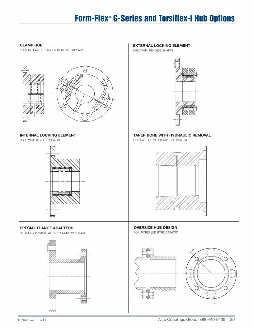
39P-7526-CG 3/14..... Altra Couplings Group 888-449-9439
Form-Flex® G-Series and Torsiflex-i Hub Options
SPECIAL FLANGE ADAPTERSDESIGNED TO MATE WITH ANY CUSTOM FLANGE
CLAMP HUBPROVIDED WITH STRAIGHT BORE AND KEYWAY
EXTERNAL LOCKING ELEMENTUSED WITH KEYLESS SHAFTS
INTERNAL LOCKING ELEMENTUSED WITH KEYLESS SHAFTS
TAPER BORE WITH HYDRAULIC REMOVALUSED WITH KEYLESS TAPERED SHAFTS
OVERSIZE HUB DESIGNFOR INCREASED BORE CAPACITY

40 Altra Couplings Group 888-449-9439 .....P-7526-CG 3/14
Coupling Design Options and Special Applications
INERTIA RING ADDED TO TORSIONALLY TUNECOMPRESSOR SYSTEM
MODIFIED TORSIFLEX-i DESIGN WITH FLANGE TO FLANGE MOUNTING Flanges designed to bolt to customer pilot and bolt patternfor test stand application.
ELECTRICAL INSULATION SPACER WITH SPLINE BORE AND EXTERNAL LOCKING ELEMENT Two piece spacer design with e-glass composite tube separating the steel halves.
FLOATING SHAFT COUPLING WITH OVER SIZED TUBE FOR INCREASED STIFFNESS AND CRITICAL SPEED WITH CUSTOM FLANGE ADAPTER Special features include oversize steel tube welded to bolted adapters for easy assembly, motor hub with integral brake disc, custom flange.

41P-7526-CG 3/14..... Altra Couplings Group 888-449-9439
MULTI-SHAFT ASSEMBLY FOR VERICAL PUMPING STATIONS USING COMPOSITE TUBE TECHNOLOGY
Coupling Design Options and Special Applications

42 Altra Couplings Group 888-449-9439 .....P-7526-CG 3/14
Disc, Bolt Thread and Tool Size Identification Chart
Coupling Series
Disc Size
Disc Dimensions (in) Bolt Nut
Width/OD ID Hole
Dia.B.C. Dia. Chord Disc Pack
ThicknessThread Dia. (in)
ThreadPitch
ThreadDesignation
HEX WAF(in)
HEX WAF(in)
Wrench Torque(lb-ft)
Form-FlexA-Series
5 1.83 1.00 0.25 1.88 1.31 0.06 0.250 28 1/4-28 0.438 0.438 8
10 2.19 1.17 0.25 2.37 1.69 0.09 0.250 28 1/4-28 0.438 0.438 8
15 2.54 1.28 0.31 2.69 1.88 0.12 0.313 24 5/16-24 0.500 0.500 17
20 2.84 1.65 0.31 3.12 2.19 0.14 0.313 24 5/16-24 0.500 0.500 17
25 3.52 1.78 0.44 3.75 2.63 0.15 0.438 20 7/16-20 0.625 0.625 40
30 4.01 2.01 0.50 4.25 3.00 0.21 0.500 20 1/2-20 0.750 0.750 58
35 4.71 2.71 0.50 5.25 3.69 0.27 0.500 20 1/2-20 0.750 0.750 58
Form-FlexG-Series
311 4.78 3.58 0.39 4.86 2.44 0.20 0.313 24 5/16-24 0.500 0.500 22
321 5.38 3.72 0.51 5.25 2.63 0.25 0.438 20 7/16-20 0.625 0.688 55
332 6.00 3.87 0.64 5.81 2.88 0.32 0.563 18 9/16-18 0.813 0.813 120
346 6.93 4.75 0.64 6.81 3.38 0.32 0.563 18 9/16-18 0.813 0.813 120
380 8.05 5.06 0.87 7.48 3.75 0.39 0.750 16 3/4-16 1.125 1.125 288
340 7.50 4.91 0.63 6.75 2.56 0.24 0.500 20 1/2-20 0.875 0.875 75
412 9.61 6.10 1.00 8.50 3.25 0.39 0.750 16 3/4-16 1.250 1.250 250
419 11.01 7.00 1.14 9.75 3.75 0.50 1.000 14 1-14 1.625 1.625 585
424 13.49 8.89 1.20 12.01 4.63 0.50 1.000 14 1-14 1.625 1.625 585
444 15.06 9.60 1.44 13.19 5.06 0.57 1.125 12 1 1/8-12 1.813 1.813 840
456 16.57 10.66 1.56 14.57 5.56 0.69 1.250 12 1 1/4-12 2.000 2.000 1,095
483 17.90 11.54 1.67 15.75 6.00 0.77 1.375 12 1 3/8-12 2.188 2.188 1,240
511 20.35 13.50 1.74 18.06 6.94 0.93 1.500 12 1 1/2-12 2.375 2.364 1,640
520 23.19 14.59 2.21 20.20 7.75 1.14 1.875 12 1 7/8-12 3.000 0.438 108
525 24.95 15.64 2.35 21.70 8.31 1.20 2.000 12 2-12 3.125 0.438 124
530 26.12 16.34 2.50 22.70 8.69 1.26 2.125 12 2 1/8-12 3.375 0.438 141
540 31.21 21.15 2.65 28.05 10.75 1.58 2.250 10 2 1/4-12 3.750 0.563 196
Form-FlexHSH/FSH
22 5.625 3.855 0.3275 4.7505 1.81 0.18 0.313 24 5/16-24 0.500 0.500 25
26 6.565 4.400 0.4055 5.5010 2.13 0.22 0.375 24 3/8-24 0.563 0.563 30
31 7.750 5.250 0.4680 6.5000 2.50 0.25 0.438 20 7/16-20 0.625 0.625 40
35 8.625 5.750 0.5315 7.2500 2.75 0.29 0.500 20 1/2-20 0.813 0.750 70
37 9.625 6.312 0.6265 8.0000 3.06 0.33 0.563 18 9/16-18 0.938 0.875 95
42 10.500 6.750 0.6885 8.6250 3.31 0.31 0.625 18 5/8-18 1.063 0.938 125
45 11.250 7.250 0.7505 9.2500 3.56 0.38 0.625 18 5/8-18 1.125 1.063 150
50 12.813 8.500 0.8755 10.5000 4.00 0.47 0.750 16 3/4/16 1.250 1.250 210
55 14.375 9.000 1.0005 11.7500 4.50 0.54 0.875 14 7/8-14 1.375 1.438 320
60 15.938 9.938 1.1270 13.0000 5.00 0.59 1.000 14 1-1/4 1.625 1.625 450
70 18.125 11.125 1.3120 14.7500 5.63 0.78 1.125 12 1 1/8-12 1.750 1.813 575
75 19.720 12.000 1.4380 16.0000 6.13 0.80 1.250 12 1 1/4-12 1.938 2.000 830
80 21.438 13.125 1.5630 17.3760 6.63 0.81 1.375 12 1 3/8-12 2.125 2.188 1000
85 22.875 14.000 1.7505 18.5000 7.06 0.88 1.500 12 1 1/2-12 2.500 2.375 1400
92 24.875 15.000 1.8760 20.0000 7.63 1.01 1.500 12 1 1/2-12 2.500 2.375 1400
92HT 24.875 15.000 1.8760 20.0000 7.63 1.01 1.750 12 1 3/4-12 2.500 2.750 2400
Form-Flex® A-Series
Form-Flex® G-SeriesSizes 311-380
Form-Flex® G-SeriesSizes 340-540
Form-Flex® HSH/FSH

43P-7526-CG 3/14..... Altra Couplings Group 888-449-9439
Application Data Sheet Project Ref: ______________________________________________________Company: ______________________________ Date: ______________________________________________________Contact: ________________________________ Email: ______________________________________________________
Replacing: ______________________________ Phone #: ________________________________________________________
SECTION I - DRIVER Electric Motor [ ] ; Engine [ ] - # Cylinders _______ ; Turbine [ ] ; Other _______________________HP: _________________ KW: ___________________ Normal Torque: ______________________Lb-in[ ] Nm[ ]Rated Speed: _____________________ Max Torque: ________________________Lb-in[ ] Nm[ ]Operating Speed: _______________________ Breakdown Torque: ___________________________Lb-in[ ] Nm[ ]
SECTION II - DRIVEN Description: ________________________________________________________________________________________________________________________________________________________________________________Load Application: Non-Pulsating [ ] Medium Pulsating [ ] Heavy Pulsating [ ] Smooth [ ] Light Shock [ ] Heavy Shock [ ]
SECTION III - COUPLING APPLICATION Min Service Factor: __________________Temerature Range: ______________ to ________________ °C [ ] or °F [ ] Hydraulic Removal: Yes [ ] No [ ]Specification: API671 [ ] Edition ___________ ; API610 [ ] Edition ___________ ; Other _______________________________Balance: Cplg [ ] Hubs [ ] Spacer [ ] Balance Specification ____________________________
SECTION IV - DIMENSIONAL DATA Distance Between Shaft Ends (DBSE): _______________________ IN [ ] MM [ ] Taper Shaft & Keyway Data
Driver DrivenShaft Dia (Straight): _______________________Shaft Dia L.E. (Taper): _______________________ _______________________Taper Ratio _______________________ _______________________Keyway Size: Width ______________ Depth_______________ Width ______________ Depth_______________KW Depth Across Bore: _______________________ _______________________
TAPER SHAFT DATA FLYWHEEL/FLANGE CONNECTION LE _________ PILOT DIA. ________ SE _________ B.C.D. ________ L _________ HOLE DIA. ________ T _________ QTY. ________ M _________ N _________ P _________
STANDARD ADAPTER SIZES
Size O.D. (in)SAE Bolting HD Bolting
P.C.D. (in) Hole Qty. Hole SizE (in) P.C.D. (in) Hole Qty. Hole Size (in)
10 10.375 9.625 6 0.406 9.500 8 0.469
12 12.375 11.625 8 0.406 11.500 8 0.531
14 13.875 13.125 8 0.406 12.500 8 0.656
18 18.375 17.250 8 0.531 16.750 8 0.781
20 20.375 19.250 8 0.531 18.500 8 0.906
22 22.500 21.375 6 0.656 20.500 8 1.031
26 26.500 25.250 12 0.656 24.500 12 1.031
28 28.875 27.250 12 0.781 26.875 12 1.031

44 Altra Couplings Group 888-449-9439 .....P-7526-CG 3/14
Additional Comments: ____________________________________________________________________________________
________________________________________________________________________________________________________
________________________________________________________________________________________________________
________________________________________________________________________________________________________
________________________________________________________________________________________________________
________________________________________________________________________________________________________
Sketch Area
Application Data Sheet

Other product solutions fromAltra Industrial MotionOur comprehensive product offering is comprised of nine major categories including electromagnetic clutches and brakes, heavy duty clutches and brakes, overrunning clutches, gearing, engineered couplings, engineered bearing assemblies, linear products and belted drives. With thousands of product solutions available, Altra provides true single source convenience while meeting specific customer requirements. Many major OEM’s and end users prefer Altra products as their No.1 choice for performance and reliability.
Linear Products
Warner Linear
Engineered Bearing Assemblies
Kilian Manufacturing
Precision Couplings and Air Motors
Huco Dynatork
Belted Drives and Sheaves
TB Wood’s
Heavy Duty Clutches and Brakes
Wichita ClutchTwiflex LimitedIndustrial ClutchSvendborg Brakes
Electromagnetic Clutches and Brakes
Warner ElectricInertia DynamicsMatrix International
Overrunning Clutches
Formsprag ClutchMarland ClutchStieber Clutch
Engineered Couplings and Universal Joints
TB Wood’sAmeridrives CouplingsAmeridrives Power TransmissionBibby Turboflex Lamiflex Couplings
Gearing
Boston GearNuttall GearDelroyd Worm GearBauer Gear Motor
The power of one, the strength of many.
www.altramotion.com

All Customer Service phone numbers shown in bold
P-7526-CG 3/14 Printed in USA
Altra Industrial Motion
www.altramotion.com
300 Granite St. Suite 201Braintree, MA 02184 - USA781-917-0600Fax: 781-843-0709
TB Wood’s1-888-829-6637 – Press #5+44 (0) 1992 501900
Bibby Turboflex+44 (0) 1924 4608011-800-779-6993
Ameridrives Couplings 1-814-480-5000
Ameridrives Power Transmission1-920-593-2444+44 (0) 1924 460801
Huco Dynatork1-888-829-6637 – Press #5+44 (0) 1992 501900
Lamiflex Couplings+55 11 5679 6553+55 11 5679 7735
Altra Couplings Group
Electromagnetic Clutches and Brakes
Warner ElectricElectromagnetic Clutches and Brakes
New Hartford, CT - USA1-800-825-6544For application assistance:1-800-825-9050
St Barthelemy d’Anjou, France+33 (0) 2 41 21 24 24
Precision Electric Coils and Electromagnetic Clutches and Brakes
Columbia City, IN - USA1-260-244-6183
Matrix InternationalElectromagnetic Clutches and Brakes, Pressure Operated Clutches and Brakes
Brechin, Scotland+44 (0) 1356 602000New Hartford, CT - USA1-800-825-6544
Inertia DynamicsSpring Set Brakes; Power On and Wrap Spring Clutch/Brakes
New Hartford, CT - USA1-800-800-6445
Linear Products
Warner LinearLinear Actuators Belvidere, IL - USA1-800-825-6544For application assistance:1-800-825-9050
St Barthelemy d’Anjou, France+33 (0) 2 41 21 24 24
Couplings
Ameridrives Couplings Mill Spindles, Ameriflex,Ameridisc
Erie, PA - USA1-814-480-5000
Gear Couplings
San Marcos, TX - USA1-800-458-0887
Bibby TurboflexDisc, Gear, Grid Couplings, Overload Clutches
Dewsbury, England+44 (0) 1924 460801Boksburg, South Africa+27 11 918 4270
TB Wood’sElastomeric Couplings
Chambersburg, PA - USA1-888-829-6637– Press #5
For application assistance:1-888-829-6637 – Press #7
General Purpose Disc Couplings
San Marcos, TX - USA1-888-449-9439
Ameridrives Power TransmissionUniversal Joints, Drive Shafts, Mill Gear Couplings
Green Bay, WI - USA1-920-593-2444
Huco DynatorkPrecision Couplings and Air Motors
Hertford, England+44 (0) 1992 501900Chambersburg, PA - USA 1-888-829-6637
Lamiflex CouplingsFlexible Couplings, Bearing Isolators, and Coupling Guards
São Paulo, SP - Brasil+55-11-5679-6533
Heavy Duty Clutches and Brakes
Wichita ClutchPneumatic Clutchesand Brakes
Wichita Falls, TX - USA1-800-964-3262Bedford, England+44 (0) 1234 350311
Twiflex LimitedCaliper Brakes and Thrusters
Twickenham, England+44 (0) 20 8894 1161
Industrial ClutchPneumatic and Oil ImmersedClutches and Brakes
Waukesha, WI - USA1-262-547-3357
Gearing
Boston GearEnclosed and Open Gearing, Electrical and Mechanical P.T. Components
Charlotte, NC - USA1-800-825-6544For application assistance:1-800-816-5608
Bauer Gear MotorGeared Motors
Esslingen, Germany+49 (711) 3518 0Somerset, NJ - USA1-732-469-8770
Nuttall Gear andDelroyd Worm GearWorm Gear and Helical Speed Reducers
Niagara Falls, NY - USA1-716-298-4100
Overrunning Clutches
Formsprag Clutch Overrunning Clutches and Holdbacks
Warren, MI - USA1-800-348-0881– Press #1
For application assistance:1-800-348-0881 – Press #2
Marland ClutchRoller Ramp and Sprag Type Overrunning Clutches and Backstops
South Beloit, IL - USA1-800-216-3515
Stieber Clutch Overrunning Clutches and Holdbacks
Heidelberg, Germany+49 (0) 6221 30 47 0
Belted Drives and Sheaves
TB Wood’sBelted Drives
Chambersburg, PA - USA1-888-829-6637 – Press #5
For application assistance:1-888-829-6637 – Press #7
EngineeredBearing Assemblies
Kilian ManufacturingEngineered Bearing Assemblies
Syracuse, NY - USA1-315-432-0700
For information concerning our sales offices in Asia Pacific check our website www.altramotion.com.cn