Embed Size (px)
Citation preview

P.O. Box 181 Wasco, IL 60175 Phone (630) 677-9233 Fax (630) 377-2705
FLEXAIR DRYER
TEST PROGRAM
Revision Date: January 2006

Page 2 of 20
INTRODUCTION
This document will help you understand how to configure and evaluate the FlexAir Dryer Test Dryer.
FlexAir’s Compressed Air Dryer Technology is being used commercially in many installations around the world in various printing, coating and laminating applications.
The FlexAir Drying Technology has been found to be a superior drying solution for printers and converters with some of the most demanding water and solvent based drying requirements including:
Adhesives
Cohesives
Security Coatings (Scratch Off)
Varnishes & Lacquers
Metallized Inks
Rigorous tests comparing FlexAir Dryers to traditional forced air and infra-red dryers have consistently demonstrated that FlexAir Drying Systems can dry virtually any evaporative system more quickly, more completely, and in the shortest web path.
The ultimate advantages to the converter are reliable and repeatable processes minimizing lost product and maximizing the press speed.

Page 3 of 20
WHY HAVE A TEST PROGRAM?
FlexAir has made test units available to the converting industry as a minimum investment tool for converters to:
1) familiarize themselves with FlexAir’s Drying Technology
2) explore the applicability of FlexAir’s Drying Technology to specific printing and coating processes.*
3) benchmark the drying process for a scaled up final dryer configuration.
FlexAir Dryers are a unique solution capable of configuring a very powerful dryer in an extremely small compact package. With hands on experience with FlexAir’s Dryer technology, the converter can quickly appreciate how easily their existing press can incorporate FlexAir dryers to maximize the printing press capacity.
The test models have been configured to integrate with minimum complexity and effort, and include provisions to integrate to the press run signal for an extended press run test.
* - In very rare instances the high velocity air has disturbed thick coatings.

Page 4 of 20
THE BASICS
Locate The Air Bars Above the Web
FlexAir’s technology uses a relatively small volume of compressed air to produce a vigorous and turbulent scrubbing action at the surface of the web. The best overall drying performance is experienced when the dryer air bar is positioned approximately 3/4” (0.750”) above the web.
Decreasing the distance below approximately 1/2” (0.500”) risks uneven drying and can disturb the applied inks and coatings.
Increasing the air-bar-to-web gap distance beyond approximately 1” (1.000”) makes the drying process less effective due to complex interactions and dynamics with the environment.
Page 5 of 20
Support The Web Adequately
The pressure exerted by the air jets can be significant, and can result with the web being pushed out of the effective drying distance. It is important that the web have sufficient support to resist being pushed away from the dryer. If the web is pushed away YOU WILL NOT dry adequately.
A free spinning idler is the best solution to minimize scratching of the backside of the web. If slight scratching can be risked (or tolerated for a short test run) consider using a solid rod or a slide plate. A slide plate can be very inexpensively constructed from a piece of corrugated paperboard.
Using a large metal drum or plate is not recommended. The drum or plate can act like a heat sink to the web and throttle the drying process. This phenomenon is most apparent with thin films and foils. Paper webs are less susceptible because paper is a fairly good insulator.

Page 6 of 20
SIMPLE BUT EFFECTIVE DEMONSTRATIONS
Some of the characteristics described above can be very easily demonstrated off-press. To appreciate the turbulence generated by the dryer, turn the dryer on its side and feel the amount of air flow at a distance of 1-2 feet.
To appreciate how little compressed air is actually being used, place the dryer enclosure face down on a table top surface. Use a piece of wood, stack of cardboard, or something similar as a shim. About 1/4 to 1/2 inch gap is adequate. With the air flowing, feel around the outside of the dryer gap and notice the negligible amount of air flowing out of the dryer enclosure.
Dryer Hood (Sheet Metal Enclosure)
Make sure the table top surface can tolerate the heat of the dryer. Use a piece of cardboard or wood to protect the surface of the table if necessary.

Page 7 of 20
To appreciate the localized heat, place your hand carefully near the jet orifices. BE CAREFUL! Once your hand is within 3/4” of the air jet orifice the temperature rises quickly. BE CAREFUL!
The question is often asked, “Will the heat damage my web when I stop the press?”
This will not be the case if the air is turned off when the press is stopped. The dryer controls are designed to interface with a Press Run Signal. If the press is stopped the air is automatically turned off but the temperature control process continues to operate. In this situation the air bars radiate very little heat.
You can demonstrate this to yourself quite easily by feeling the radiation with your hand. As long as the air is off you can safely bring your hand right next to the air bar. BE CAREFUL! – DO NOT physically touch the air bar. It is HOT! BE CAREFUL!
NO AIR!

Page 8 of 20
HOOKING UP THE FLEXAIR DRYERS
You have received a set of equipment that has been selected by FlexAir. The selection process is based on discussions with you regarding your printing or converting equipment, available electrical and compressed air utilities and your testing objectives.
The entire FlexAir system can be broken down into three basic parts:
1) The FlexAir Dryers using a series of FlexAir’s Patented Air Bars.
2) An Electrical Heating and microprocessor based Temperature Control System.
3) A pneumatic air flow and pressure control system.
In general, mounting brackets required for supporting the dryers will be your responsibility for the testing program.
Electrical Power Supply Connections
FlexAir strives to configure the electrical utility supply connection using standard NEMA-Style Turn Lock Plugs for industrial single phase and three phase voltages. The NEMA-Style, receptacle electrical utilities description, and McMaster Carr part number for the receptacle are included for your convenience. These can be easily and quickly obtained through www.mcmaster.com. Virtually any electrical supply distributor and many hardware stores carry these receptacles.
NEMA- Style Electrical Utility Description Receptacle P/N (McMaster Carr)
L14-20 Combined 250V and 125V Single Phase 20 Amps
7164K43*
L14-30 Combined 250V and 125V Single Phase 30 Amps
7164K56*
L15-20 Three Phase 250V 20 Amps
7164K47*
L15-30 Three Phase 250V 30 Amps
7164K5*
L16-20 Three Phase 480V 20 Amps
7164K53*
L16-30 Three Phase 480V 30 Amps
7164K59*
* - Always verify that the part number matches the NEMA-Style and description

Page 9 of 20
NEMA-STYLE TWIST-LOCK PLUG AND RECEPTACLE WIRING DIAGRAMS FOR
INDUSTRIAL ELECTRICAL POWER

Page 10 of 20
COMPRESSED AIR CONNECTIONS
FlexAir Dryers are generally designed to be compatible with low pressure compressed air systems (approx 50 psi) and typical mill compressed air (80-110 psi). All the compressed air control components such as regulators and fittings are typically rated for 150 psi.
It is assumed that for your test, you will utilize compressed air pressure between 80-150 psi.
Compressed Air Quality
It is important that the compressed air supply is clean of liquid water and oil for a valid trial. Compared to typical compressed air applications - air tools, pneumatic cylinders, etc. - FlexAir Dryers use two times or more air volume. If your plant does not move much air through its lines, it is possible that accumulated oil and moisture will be flushed out of your lines within a few minutes of the dryer’s operation. Although this will not necessarily damage the FlexAir Dryers it may take considerable time for the internal oil and water to work (“cook”) itself out of the components.
If your compressed air is not filtered at the compressor, it is very strongly advised for you to filter the compressed air prior to the compressed air inlet of the FlexAir equipment. The Filter must be sized adequately to the air consumption of the FlexAir Dryer(s) so as not to starve the dryer during you trials.
Connecting the Compressed Air Supply
FlexAir configures the pneumatic controls in two formats:
1) Integrated Dryer Air Flow Regulator
2) Remote Dryer Air Flow Regulator
The location of the Dryer Air Flow Regulator depends on the volume of air required by the FlexAir Dryer and where the operator controls are located compared to the location of the dryer.
If the Dryer Air Flow Regulator is integrated into the control cabinet, you will simply need to:
1) connect the compressed air supply directly to the Control Enclosure.
2) connect the supplied tubing hose between the Control Enclosure and the FlexAir Dryer.
The ports and fittings are clearly labeled on the control cabinet.
Page 11 of 20
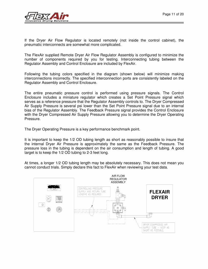
If the Dryer Air Flow Regulator is located remotely (not inside the control cabinet), the pneumatic interconnects are somewhat more complicated.
The FlexAir supplied Remote Dryer Air Flow Regulator Assembly is configured to minimize the number of components required by you for testing. Interconnecting tubing between the Regulator Assembly and Control Enclosure are included by FlexAir.
Following the tubing colors specified in the diagram (shown below) will minimize making interconnections incorrectly. The specified interconnection ports are consistently labeled on the Regulator Assembly and Control Enclosure.
The entire pneumatic pressure control is performed using pressure signals. The Control Enclosure includes a miniature regulator which creates a Set Point Pressure signal which serves as a reference pressure that the Regulator Assembly controls to. The Dryer Compressed Air Supply Pressure is several psi lower than the Set Point Pressure signal due to an internal bias of the Regulator Assembly. The Feedback Pressure signal provides the Control Enclosure with the Dryer Compressed Air Supply Pressure allowing you to determine the Dryer Operating Pressure.
The Dryer Operating Pressure is a key performance benchmark point.
It is important to keep the 1/2 OD tubing length as short as reasonably possible to insure that the internal Dryer Air Pressure is approximately the same as the Feedback Pressure. The pressure loss in the tubing is dependent on the air consumption and length of tubing. A good target is to keep the 1/2 OD tubing to 2-3 feet long.
At times, a longer 1/2 OD tubing length may be absolutely necessary. This does not mean you cannot conduct trials. Simply declare this fact to FlexAir when reviewing your test data.
MICROCONTROLLER
MAN
RUN
HOLD
ON
OFF
AUTO
Fax: (630) 377-2705 www.flexairinc.comP.O. Box 181 Wasco, IL 60183-181 Phone: (630) 677-9233
U.S. Patent Pending Technology
AIR FLOW REGULATOR ASSEMBLY
FLEXAIR DRYER

Page 12 of 20
Remote Dryer Air Flow Regulator Assembly (Interconnection Diagram)

Page 13 of 20
OPERATING THE DRYER
The FlexAir Control System is configured to control the FlexAir Dryer Operating Temperature and the FlexAir Dryer Operating Pressure. The Control Enclosure supplied by FlexAir for you trials is a common design supplied with a purchased unit. Some variations will exist but are typically not critical for your trial.
The Main Switch has three positions: ON, OFF and AUTO. The following table outlines what is being controlled in each mode.
ON Mode OFF Mode AUTO Mode
Air Pressure ON Continuously OFF ON when machine is running, otherwise
OFF
Temperature Control
ON Continuously OFF ON Continuously
The AUTO Mode requires an interconnection with the press run signal. This signal is rarely used for field trials, however, this can be easily accomplished if required. Please consult FlexAir if you feel this feature is valuable for your trials.
FlexAir Dryers are designed to be heated without airflow. The Temperature Controller is programmed to limit the maximum set point temperature so that any overshoots will not damage the FlexAir Dryers. Typically this maximum is set by FlexAir to 275 degrees Fahrenheit.
During the actual trials when materials are being printed/coated and dried, the Main Switch is set to ON. When the process is stopped, the Main Switch is turned manually to AUTO to maintain the temperature of the dryer without consuming compressed air.
When the process is stopped, you can turn the switch to OFF, but the drier will gradually cool down requiring you to bring the dryer back up to temperature when you restart your process. The temperature ramp up time can be several minutes depending on your Set Point Temperature.
It is advised to allow the dryer to come up to temperature without air flow allowing the shortest temperature ramp up time. This can be achieved by turning the Main Switch to AUTO, or by turning the Main Switch to ON and turning down the Dryer Operating Pressure.

Page 14 of 20
Adjusting the SET POINT TEMPERATURE
The SET POINT TEMPERATURE is the target temperature at which you want to operate the FlexAir Dryers. The Set Point Temperature can be changed manually by the operator.
To RAISE the Set Point Temperature press the (٭) and (▲) buttons simultaneously.
To LOWER the Set Point Temperature, press the (٭) and (▼) buttons simultaneously.
The ACTUAL TEMPERATURE is the temperature of the FlexAir Dryer as sensed by the thermocouple. It cannot be changed by the operator.
The CONTROLLER OUTPUT LIGHT indicates when the temperature controller commands the Heater Power to be turned on.
The CONTROLLER OUTPUT LIGHT is ON steadily when the system is being heated up. During normal operation when the ACTUAL TEMPERATURE is at or near the SET POINT TEMPERATURE the CONTROLLER OUTPUT LIGHT flashes. The amount of time the CONTROLLER OUTPUT LIGHT remains on is a good indicator of how much electrical power is being consumed by the dryer.
For example, if the CONTROLLER OUTPUT LIGHT is on about the same amount of time that it is off, the FlexAir Dryer is operating near a 50% duty cycle.
The duty cycle will vary depending on the FlexAir Dryers SET POINT TEMPERATURE and SET POINT PRESSURE.
Note that when the air is turned off and the dryer is near the SET POINT TEMPERATURE the CONTROLLER OUTPUT LIGHT rarely flashes. This means that without airflow the FlexAir Dryer is consuming negligible electrical power to maintain its temperature.
ACTUAL TEMPERATURE
SET POINT TEMPERATURE
CONTROLLER OUTPUT LIGHT

Page 15 of 20
Adjusting the SET POINT PRESSURE
The SET POINT PRESSURE is the target pressure at which you want to operate the FlexAir Dryer. The Set Point Pressure can be changed manually by the operator by adjusting the Set Point Pressure Regulator.
The Pressure Gauge near the Set Point Regulator displays the Dryer Compressed Air Supply Pressure. The Pressure Gauge does not display the output pressure of the Set Point Regulator. The compressed air must be flowing through the Dryer to for the Pressure Gauge to function.
Turning the Main Switch to ON mode will command the compressed air to flow into the FlexAir Dryer. If the Main Switch is turned to AUTO mode, the compressed air will only flow if the press run signal is activated while the press is running.
To RAISE the Set Point Pressure turn the Regulator Knob clockwise.
To LOWER the Set Point Pressure turn the Regulator Knob counter-clockwise.
The Pressure Gauge is a 0-30 psi gauge. FlexAir Dryers are intended for operation between 5 and 30 psi. It is possible to achieve higher Dryer Operating Pressures if your supply lines and compressor capacity is adequate.
Below we discuss the advantages and disadvantages to running at higher pressures.
SET POINT PRESSURE
REGULATOR
DRYER OPERATING PRESSURE
Page 16 of 20
OPERATING TEMPERATURE AND PRESSURE FOR YOUR PROCESS
The FlexAir Dryer Operating Temperature and Operating Pressure set points can be adjusted as dictated by your printing process and your curiosity.
A nominal starting point is 180 degrees Fahrenheit and 18-psi gauge pressure.
Improved drying can be achieved by increasing Pressure, Temperature or both.
Generally speaking,
• higher pressure is more effective at improving evaporative drying
• higher pressure can cause disturbance to the print and/or substrate.
• higher pressure moves more air through the air bar. The more air moving through the air bar, the lower the maximum achievable temperature.
• higher temperatures are typically required for slow solvents (higher flash or boiling point temperatures).
• higher temperatures can present a heat load to sensitive mechanical components. For example, central impression drums can deform modestly when heated causing an uneven surface behind the substrate.
The dryer unit you are testing may not be a final design solution for your process. However, important criterion can be determined by testing at various temperatures, pressures and press speeds. The flexographic and gravure processes are used for an amazing variety of applications. Ink and coating chemistries and film structures are proprietary and the compatibility of the inks and webs are rarely apparent. A broad spectrum of dryer settings may require testing before identifying the ideal setting.
In certain cases the test dryer can be rotated to be inline with the web instead of across the web. Although the dryer will no longer dry across the entire web width, it can provide a comparison of drying across a narrower lane of web. This lane will experience a longer dwell time under the dryer. The achievable press speeds between the dryer’s two orientations provide valuable data to recommend a final dryer dwell time.
There are many varying characteristics that ultimately achieve an acceptable product. Evaporative drying is not necessarily the only requirement.
Certain film and ink/coating combinations must experience an elevated temperature which achieves a good bond. This is sometimes referred to as “kicking over” the inks. If the process does not achieve the threshold temperature the inks may not pin (stick) adequately to the web resulting in blocking, or poor scratch resistance.
In other instances, slow solvent ink additives which help ink flow, gloss, foaming and other characteristics, can only be driven out of the inks at elevated temperatures. Although the ink or coating appears dry, the retained solvents can cause offensive smells, damage laminations, rewet underlying inks, etc.

Page 17 of 20
The FlexAir Test Dryers can be adjusted to higher temperatures. The Temperature Controller has been programmed to limit the Set Point Temperature to 275 F. If you feel it is necessary to test above this temperature, please contact FlexAir for instructions to reprogram the controller.
Note that at higher pressures the heating elements may not have sufficient power to heat the increased volume of air moving through the air bar. If you see this condition, reducing the operating pressure will help elevate the operating temperature.
If you suspect that your process requires an elevated “kick over” temperature, you may also need to reduce the press speed to give the web sufficient exposure to the dryer in order for the web to heat up adequately.
Please do not hesitate to call FlexAir if you would like to discuss your equipment or process.

Page 18 of 20
A BRIEF TECHNICAL REVIEW OF THE FLEXAIR DRYER CONTROL SYSTEM
The FlexAir Temperature Controller is a micro-processor controlled unit. It is a PID (Proportional, Integral, and Derivative) controller. This means that the controller uses history to determine how it controls the output. The controller’s output is used to pulse electrical power to the heating elements. The pulse is either ON or OFF.
The controller monitors the temperature of the FlexAir Dryers. The history is typically 2-10 minutes of the past Dryer Temperature Feedback compared with the controller’s Heater Power Output. This history is used by the controller to determine how it pulses the heater power.
The temperature controller does not monitor any additional information. The temperature controller does not, for instance, know if the air is flowing through the dryer or not. Since the air flow removes heat from the dryer the FlexAir Dryer will heat up at different rate depending on, or if, air is flowing and how much is flowing – air flow is higher with higher Operating Pressures.
The Heating Elements heat the dryer from the inside out and it takes some time for the temperature monitoring device (the thermocouple) to sense the temperature. This means that your temperature is not sensed instantaneously. In technical terms, the overall system is called a passive system.
A characteristic of a passive system is a lagged response resulting in overshoots and undershoots during changes (turning the dryer on, turning air on/off). A passive system is also very stable once the system is at a continuous operating condition.
It is normal for the dryer to take several minutes to come up to temperature from a cold start. It is also normal to experience temperature overshoots of 25 or more degrees, and to see the temperature drop by a similar value when air is first turned on. It is acceptable to consider that the dryer is at temp within 5 degrees of the Set Point Temperature.
When the temperature drops you may notice that the temperature controller is commanding the Heater Power ON. This means that the heating elements are heating the air flowing through the air bars but the heat has not worked its way to the thermocouples.
FlexAir’s experience has shown that 10-20 degree changes show no apparent difference in how the process is drying. Typically much greater changes to the Set Point Temperature are required to notice a considerable difference with the process.
FlexAir’s experience has been that changes to the Set Point Pressure have much more dramatic effects.
Page 19 of 20
HOOKING UP THE PRESS RUN SIGNAL
The FlexAir Control System can be interfaced with the printing press. The fundamental difference in AUTO mode is that the FlexAir Dryer is pressurized automatically only while the press is running. In AUTO or ON mode, the temperature control system is operational regardless of the dryer being pressurized or not.
The value of using AUTO mode is to conserve energy when the press is stopped.
In order to run in AUTO mode, the dryer system must receive a signal from the main press controls. FlexAir supplies a 120VAC source and return signal. The interconnection points are specified on the Schematic and the Control Enclosure Assembly.
These two signals must be interconnected to a set of dry-contacts on the main press controls. The dry contacts “close” when the press is running. Test Jumpers are installed in the Press Controls Interface terminal blocks (See the Control Enclosure Assembly Drawing). A label is typically placed near the jumpers. If the jumpers are present, they need to be removed if the system is to respond to press command signals (dry contacts from press).
FlexAir utilizes WAGO cage clamp style terminal blocks. In order to land the wire into the WAGO terminal block, a screwdriver must be inserted into the terminal block operating-slot to relieve the cage clamp spring. The stripped wire is then inserted into the clamping unit. The screwdriver is removed thus clamping the wire securely. Additional information can be found at www.wago.com or WAGO Corporation at 1-800-346-7245.

Page 20 of 20
FINDING THE RIGHT FLEXAIR DRYER DESIGN FOR YOUR PROCESS
FlexAir’s proprietary technology is extremely versatile. FlexAir is an engineering driven organization and our products are more-often-than-not custom designed.
Experience has shown that the same press in different converter’s facilities may not necessarily allow a common FlexAir Dryer design. Differences in web paths, peripheral equipment, etc. all impact the final design.
The correct solution for you application may be as simple as a single air bar positioned over an open span of web, or as complicated as 30 foot tunnel with multiple temperature and pressure controlled zones.
Do not hesitate to ask “What if . . . ?
FlexAir will gladly help you explore if your idea is the right solution for you.