Embed Size (px)
Citation preview
Flex Mitigation Technology
April 2009

Topics to cover Today
• Mechanical Cracking of MLCC’s •Background •Causes •Prevention
• Current Flex Mitigation Technologies •Features, benefits, and capabilities •Markets & Applications •Potential customers •Competitors •Questions you need to ask.
• Upcoming Technologies • Q&A

What is a Mechanical crack?
#1 MLCC Failure Mode
What is a Mechanical crack?
•Mechanical damage that occurs when handling and/or mounting Multilayer Ceramic Capacitors.
•Two Main Causes •Impact Cracking
•Occurs during placement onto a PCB. • Improper setup of pick and place machine.
•Flex Cracking •Occurs during board flexure or bending..
•Excessive bending of PCB post soldering.

What is a "Flex Crack?"
Ceramic Chip
Terminations
Solder
SMT Pads
Crack

When/where do flex cracks occur?
Depanelization Hardware application Mounting in assembly Unsupported IO edge connectors Stacked in process Pushed "to fit" Unsupported Pick & Place Mismatch in TCE (IR soldered then Wave)
ANY post-mount handling that creates excessive bending of the board
Manufacturing defects of MLCC’s have been systematically eliminated
These failures are now at a PPM level

Prevention
•Board Flex cannot be eliminated at KEMET or any other capacitor manufacturer.
•2 Convergent Paths: •Education: Change board assembly and handling techniques. •Engineering: Mitigate effects of board flex cracks
KEMET offers one of the most comprehensive Flex-Mitigation Portfolios available in the
Industry.

Flex Mitigation Portfolio
www.kemet.com/flex
Current Flex Portfolio Technologies
•Floating Electrode FE CAP
•Open Mode
•Flexible Termination FT CAP
•Floating Electrode + Flexible Termination FF CAP
AEC Q200 Qualified

Flex Mitigation Technology: Select the right level of protection for your application
Level 0: NO Crack Protection
Standard MLCC Target Applications: Non-Critical Fail-Short Condition Up to 2mm flex bend capability
Level I: Basic Level of Crack Protection Floating Electrode or Open-
Mode Target Applications: Semi - Critical Fail-Open Condition Up to 2mm flex bend capability
Level III: High Level of Crack Protection
Floating Electrode plus Flexible Termination
Open Mode plus
Flexible Termination Target Applications: Safety Critical Combines Fail -Safe electrode designs with tear-away, termination technology. Provides for a high level of protection from thermal stress cracks, pick-and-place damage, and board flex stress Fail-Open Condition Up to 5mm flex bend capability.
Level II: Intermediate Level of Crack Protection
Flexible Termination Target Applications: Critical Flexible termination provides for a high level of protection from thermal stress cracks, pick-and-place damage, and board flex stress Fail-short Condition Up to 5mm flex bend capability.

Level 0: NO Crack Protection
Standard MLCC Target Applications: Non-Critical Fail-Short Condition Up to 2mm flex bend capability
Level I: Basic Level of Crack Protection Floating Electrode or Open-
Mode Target Applications: Semi - Critical Fail-Open Condition Up to 2mm flex bend capability
Level III: High Level of Crack Protection
Floating Electrode plus Flexible Termination
Target Applications: Safety Critical Combines cascading electrode design with tear-away, termination technology. Provides for a high level of protection from thermal stress cracks, pick-and-place damage, and board flex stress Fail-Open Condition Up to 5mm flex bend capability.
Level II: Intermediate Level of Crack Protection
Flexible Termination Target Applications: Critical Flexible termination provides for a high level of protection from thermal stress cracks, pick-and-place damage, and board flex stress Fail-short Condition Up to 5mm flex bend capability.
Flex Mitigation Technology: Level 0 – Standard MLCC Design

www.kemet.com/flex
Flex Mitigation Technology: Level 0 – Standard MLCC Design
Standard MLCC design.
No crack protection.
Allows for up to 2mm Flex bend capability (Industry Standard)
Recommended for non-critical applications
Flex crack could result in a fail-short condition ( Catastrophic Failure)

Level 0: NO Crack Protection
Standard MLCC Target Applications: Non-Critical Fail-Short Condition Up to 2mm flex bend capability
Level I: Basic Level of Crack Protection Floating Electrode or Open-
Mode Target Applications: Semi - Critical Fail-Open Condition Up to 2mm flex bend capability
Level III: High Level of Crack Protection
Floating Electrode plus Flexible Termination
Target Applications: Safety Critical Combines cascading electrode design with tear-away, termination technology. Provides for a high level of protection from thermal stress cracks, pick-and-place damage, and board flex stress Fail-Open Condition Up to 5mm flex bend capability.
Level II: Intermediate Level of Crack Protection
Flexible Termination Target Applications: Critical Flexible termination provides for a high level of protection from thermal stress cracks, pick-and-place damage, and board flex stress Fail-short Condition Up to 5mm flex bend capability.
Flex Mitigation Technology: Level I – Floating Electrode / Open Mode

www.kemet.com/flex
Flex Mitigation Technology: Level I – Basic Level of Crack Protection
Floating Electrode FE CAP
Open Mode
www.kemet.com/flex
Flex Mitigation Technology: Level I – Open Mode
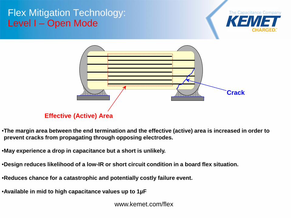
•The margin area between the end termination and the effective (active) area is increased in order to prevent cracks from propagating through opposing electrodes.
•May experience a drop in capacitance but a short is unlikely.
•Design reduces likelihood of a low-IR or short circuit condition in a board flex situation. •Reduces chance for a catastrophic and potentially costly failure event.
•Available in mid to high capacitance values up to 1µF
Effective (Active) Area
Crack

www.kemet.com/flex
Flex Mitigation Technology: Level I – Floating Electrode FE CAP
•Serial design commonly seen in High Voltage MLCC’s.
•May experience a drop in capacitance but a short is unlikely.
•Design reduces likelihood of a low-IR or short circuit condition in a board flex situation. •Reduces chance for a catastrophic and potentially costly failure event.
•Available in low to mid capacitance values less than 1µF.
Effective (Active) Areas Crack

Level 0: NO Crack Protection
Standard MLCC Target Applications: Non-Critical Fail-Short Condition Up to 2mm flex bend capability
Level I: Basic Level of Crack Protection Floating Electrode or Open-
Mode Target Applications: Semi - Critical Fail-Open Condition Up to 2mm flex bend capability
Level III: High Level of Crack Protection
Floating Electrode plus Flexible Termination
Target Applications: Safety Critical Combines cascading electrode design with tear-away, termination technology. Provides for a high level of protection from thermal stress cracks, pick-and-place damage, and board flex stress Fail-Open Condition Up to 5mm flex bend capability.
Level II: Intermediate Level of Crack Protection
Flexible Termination Target Applications: Critical Flexible termination provides for a high level of protection from thermal stress cracks, pick-and-place damage, and board flex stress Fail-short Condition Up to 5mm flex bend capability.
Flex Mitigation Technology: Level II – Flexible Termination

Flex Mitigation Technology: Level II – Flexible Termination
• Standard Termination
• Flexible Terminations Cu
Sn
Conductive Epoxy
Ceramic Body
Ni
Cu
Sn Ceramic
Body Ni

•Reduces stresses transmitted to the brittle ceramic body.
•Stresses are transferred to the end terminations.
•Maintains circuit Integrity in extreme flex environments.
•Reduces chance for a catastrophic and potentially costly failure event.
•Up to 5mm of bend flex capability. •Fail short failure mode if overstressed.
.Improved temperature cycling performance over standard termination system.
Flex Mitigation Technology: Level II – Flexible Termination
Termination Tear
www.kemet.com/flex

Level 0: NO Crack Protection
Standard MLCC Target Applications: Non-Critical Fail-Short Condition Up to 2mm flex bend capability
Level I: Basic Level of Crack Protection Floating Electrode or Open-
Mode Target Applications: Semi - Critical Fail-Open Condition Up to 2mm flex bend capability
Level III: High Level of Crack Protection
Floating Electrode plus Flexible Termination
Open Mode plus
Flexible Termination Target Applications: Safety Critical Combines Fail -Safe electrode designs with tear-away, termination technology. Provides for a high level of protection from thermal stress cracks, pick-and-place damage, and board flex stress Fail-Open Condition Up to 5mm flex bend capability.
Level II: Intermediate Level of Crack Protection
Flexible Termination Target Applications: Critical Flexible termination provides for a high level of protection from thermal stress cracks, pick-and-place damage, and board flex stress Fail-short Condition Up to 5mm flex bend capability.
Flex Mitigation Technology: Level III – Hybrid Technology

KEMET FF-CAP is built to give designers one of the best possible choices for safety critical applications:
• Flexible Termination – Tear away technology.
• High mechanical performance able to withstand up to 5mm bend flex. • Floating Electrode Design
• Open failure mode when products are overstressed. • Available in low to mid capacitance values.
Termination Tear
Crack
Flex Mitigation Technology: Level III – Flexible Termination plus Floating Electrode.
www.kemet.com/flex

KEMET FO-CAP is built to give designers one of the best possible choices for safety critical applications:
• Flexible Termination – Tear away technology.
• High mechanical performance able to withstand up to 5mm bend flex. • Open Mode Design
• Open failure mode when products are overstressed. • Available in Mid to High capacitance values.
Flex Mitigation Technology: Level III – Flexible Termination plus Open Mode.
www.kemet.com/flex Effective (Active) Area
Crack
Termination Tear

Portfolio Summary
www.kemet.com/flex

Current Flex Crack Mitigation Technologies
Technology Target Values Failure Mode Flex Capability Example
Floating Electrode “FE CAP”
Low to Mid Capacitance Open 2mm
Open Mode Mid to High Capacitance Open 2mm
Flexible Termination “FT CAP”
High Capacitance
Short Up to 5 mm
Floating Electrode +
Flexible Termination “FF CAP”
Low to Mid Capacitance Open Up to 5mm
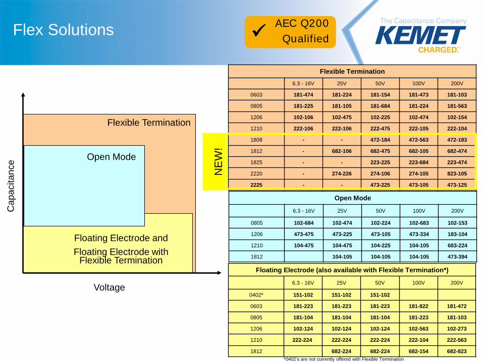
Flex Solutions
Flexible Termination
Cap
acita
nce
Voltage
Floating Electrode and Floating Electrode with
Flexible Termination
Open Mode
Flexible Termination
6.3 - 16V 25V 50V 100V 200V
0603 181-474 181-224 181-154 181-473 181-103
0805 181-225 181-105 181-684 181-224 181-563
1206 102-106 102-475 102-225 102-474 102-154
1210 222-106 222-106 222-475 222-105 222-104
1808 - - 472-184 472-563 472-183
1812 - 682-106 682-475 682-105 682-474
1825 - - 223-225 223-684 223-474
2220 - 274-226 274-106 274-105 823-105
2225 - - 473-225 473-105 473-125
Open Mode
6.3 - 16V 25V 50V 100V 200V
0805 102-684 102-474 102-224 102-683 102-153
1206 473-475 473-225 473-105 473-334 183-104
1210 104-475 104-475 104-225 104-105 683-224
1812 104-105 104-105 104-105 473-394
Floating Electrode (also available with Flexible Termination*)
6.3 - 16V 25V 50V 100V 200V
0402* 151-102 151-102 151-102
0603 181-223 181-223 181-223 181-822 181-472
0805 181-104 181-104 181-104 181-223 181-103
1206 102-124 102-124 102-124 102-563 102-273
1210 222-224 222-224 222-224 222-104 222-563
1812 682-224 682-224 682-154 682-823
AEC Q200 Qualified
*0402’s are not currently offered with Flexible Termination
NE
W!

Applications & Markets
www.kemet.com/flex
www.kemet.com/flex
Flex Mitigation Technology: Applications & Markets
Applications: •Circuits with a direct battery or power source connection. •Critical and safety relevant circuits without (integrated) current limitation. •Any application that is subject to high levels of board flexure or temperature cycling. Examples •Raw Power Input side filtering (power plane/bus) •High current applications (automobile battery line) •Circuits that cannot be fused to open. Markets: Consumer Medical Industrial (Power supply) Automotive Aerospace Telecom
www.kemet.com/flex
Flex Mitigation Technology: Potential Customers
Automotive:
Bose
Delphi
Lear
Continental
Bosch
Temic
TRW
Valeo
Visteon
Power Supplies:
Artesyn
Aztec
Delta
Lambda
Power One
ITT Power Solutions
TRC Electronics
Lineage Power
Kaga Electronics

Questions You Need To Ask
www.kemet.com/flex
www.kemet.com/flex
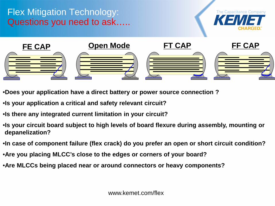
Flex Mitigation Technology: Questions you need to ask…..
FE CAP Open Mode FF CAP FT CAP
•Does your application have a direct battery or power source connection ?
•Is your application a critical and safety relevant circuit?
•Is there any integrated current limitation in your circuit?
•Is your circuit board subject to high levels of board flexure during assembly, mounting or depanelization?
•In case of component failure (flex crack) do you prefer an open or short circuit condition?
•Are you placing MLCC’s close to the edges or corners of your board?
•Are MLCCs being placed near or around connectors or heavy components?
Ordering Information
www.kemet.com/flex
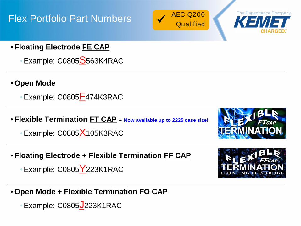
Flex Portfolio Part Numbers
• Floating Electrode FE CAP
•Example: C0805S563K4RAC
• Open Mode
•Example: C0805F474K3RAC
• Flexible Termination FT CAP – Now available up to 2225 case size!
•Example: C0805X105K3RAC
• Floating Electrode + Flexible Termination FF CAP
•Example: C0805Y223K1RAC
• Open Mode + Flexible Termination FO CAP
•Example: C0805J223K1RAC
AEC Q200 Qualified

Upcoming Flex Mitigation Technology
LEVEL IV
www.kemet.com/flex
Commercial Stacks
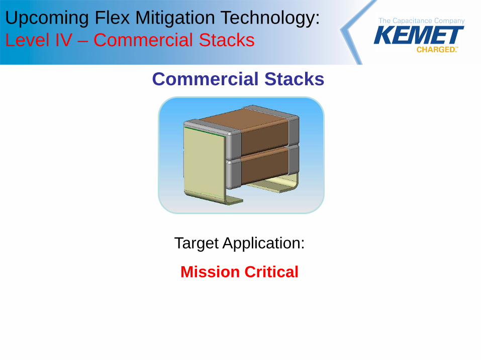
Upcoming Flex Mitigation Technology: Level IV – Commercial Stacks
Target Application:
Mission Critical

Question & Answer
www.kemet.com/flex