Embed Size (px)
Citation preview

1/8” Drill Bit
Turn Up/Down Tool
Multi-Grips
Gloves Safety Glasses Step Ladder Silicone Gun & Silicone
Power Drill 5/16” Hex Head Adapter Permanent Marker Tin Snips
Rivet Gun Tape Measure Phillips Head Adapter Spirit Level
INSTALLATIONGUIDE
BEFORE YOU START
TOOLS REQUIRED
Flat Roof Homesheds TM
It is important to check your Local Government Authority requirements before the installation of your new Stratco Flat Roof Homeshed. Read
these instructions thoroughly before starting your project and refer to them constantly during each stage of construction. Contact Stratco for
advice if you do not have the necessary tools or information.
Before starting, lay out the main components on the ground in order of assembly and check them against the delivery note. The ‘Components’
section identifies each part of your Flat Roof Homeshed.
Ensure there is reasonable access for materials and working space, ensure the shed site is level and consider the disposal of run-off water.
All tools are available from your local Stratco Home Improvement Store.
Onto Concrete
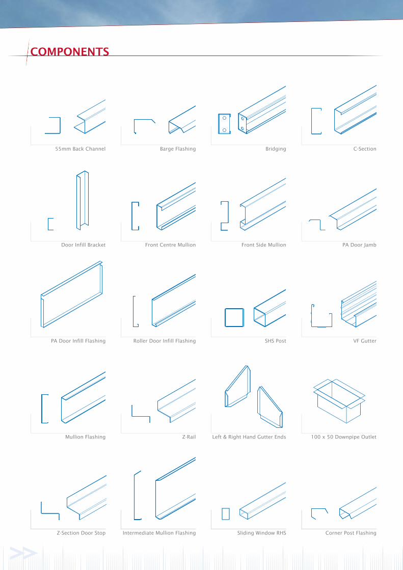
COMPONENTS
Mullion Flashing Z-Rail Left & Right Hand Gutter Ends 100 x 50 Downpipe Outlet
PA Door Infill Flashing Roller Door Infill Flashing SHS Post VF Gutter
Door Infill Bracket Front Centre Mullion Front Side Mullion PA Door Jamb
55mm Back Channel Barge Flashing Bridging C-Section
Z-Section Door Stop Intermediate Mullion Flashing Sliding Window RHS Corner Post Flashing
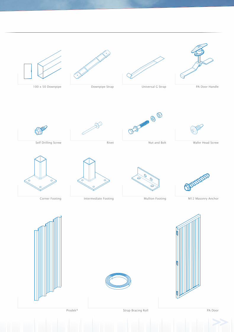
100 x 50 Downpipe Downpipe Strap Universal G Strap PA Door Handle
Self Drilling Screw Rivet Nut and Bolt Wafer Head Screw
PA DoorProdek®
Corner Footing Intermediate Footing Mullion Footing M12 Masonry Anchor
Strap Bracing Roll
G
D
D
B
C
C
FE E
A
G
REARWALL
ROLLERDOOREND
H
I
25mm
J
J
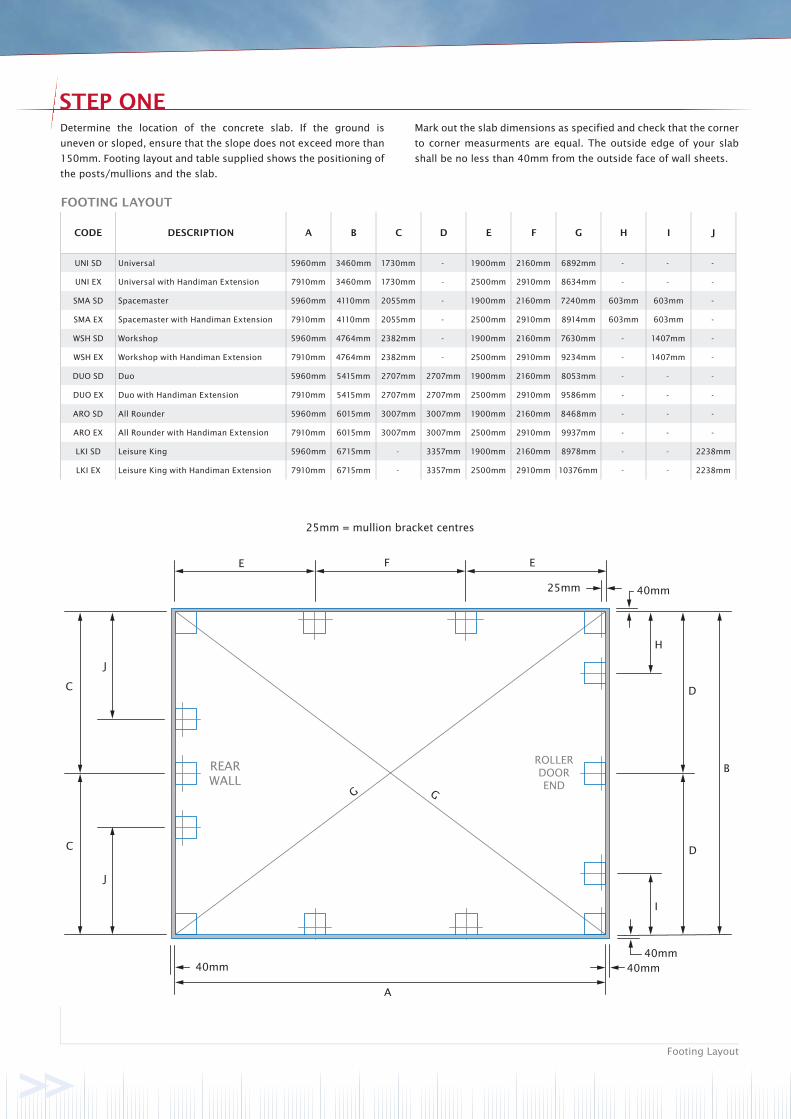
25mm = mullion bracket centres
40mm
40mm40mm40mm
STEP ONE
Footing Layout
Determine the location of the concrete slab. If the ground is
uneven or sloped, ensure that the slope does not exceed more than
150mm. Footing layout and table supplied shows the positioning of
the posts/mullions and the slab.
Mark out the slab dimensions as specified and check that the corner
to corner measurments are equal. The outside edge of your slab
shall be no less than 40mm from the outside face of wall sheets.
FOOTING LAYOUT
CODE DESCRIPTION A B C D E F G H I J
UNI SD Universal 5960mm 3460mm 1730mm - 1900mm 2160mm 6892mm - - -
UNI EX Universal with Handiman Extension 7910mm 3460mm 1730mm - 2500mm 2910mm 8634mm - - -
SMA SD Spacemaster 5960mm 4110mm 2055mm - 1900mm 2160mm 7240mm 603mm 603mm -
SMA EX Spacemaster with Handiman Extension 7910mm 4110mm 2055mm - 2500mm 2910mm 8914mm 603mm 603mm -
WSH SD Workshop 5960mm 4764mm 2382mm - 1900mm 2160mm 7630mm - 1407mm -
WSH EX Workshop with Handiman Extension 7910mm 4764mm 2382mm - 2500mm 2910mm 9234mm - 1407mm -
DUO SD Duo 5960mm 5415mm 2707mm 2707mm 1900mm 2160mm 8053mm - - -
DUO EX Duo with Handiman Extension 7910mm 5415mm 2707mm 2707mm 2500mm 2910mm 9586mm - - -
ARO SD All Rounder 5960mm 6015mm 3007mm 3007mm 1900mm 2160mm 8468mm - - -
ARO EX All Rounder with Handiman Extension 7910mm 6015mm 3007mm 3007mm 2500mm 2910mm 9937mm - - -
LKI SD Leisure King 5960mm 6715mm - 3357mm 1900mm 2160mm 8978mm - - 2238mm
LKI EX Leisure King with Handiman Extension 7910mm 6715mm - 3357mm 2500mm 2910mm 10376mm - - 2238mm
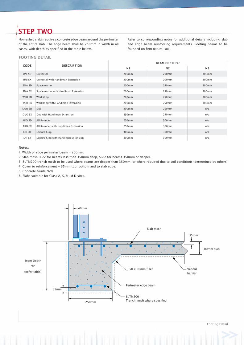
Beam Depth
‘G’
(Refer table)
Perimeter edge beam
Vapour
barrier
Slab mesh
250mm
35mm
100mm slab
35mm
8LTM200Trench mesh where specified
50 x 50mm fillet
40mm
STEP TWO
Footing Detail
Homeshed slabs require a concrete edge beam around the perimeter
of the entire slab. The edge beam shall be 250mm in width in all
cases, with depth as specified in the table below.
Refer to corresponding notes for additional details including slab
and edge beam reinforcing requirements. Footing beams to be
founded on firm natural soil.
FOOTING DETAIL
CODE DESCRIPTIONBEAM DEPTH ‘G’
N1 N2 N3
UNI SD Universal 200mm 200mm 300mm
UNI EX Universal with Handiman Extension 200mm 200mm 300mm
SMA SD Spacemaster 200mm 250mm 300mm
SMA EX Spacemaster with Handiman Extension 200mm 250mm 300mm
WSH SD Workshop 200mm 250mm 300mm
WSH EX Workshop with Handiman Extension 200mm 250mm 300mm
DUO SD Duo 200mm 250mm n/a
DUO EX Duo with Handiman Extension 250mm 250mm n/a
ARO SD All Rounder 250mm 300mm n/a
ARO EX All Rounder with Handiman Extension 250mm 300mm n/a
LKI SD Leisure King 300mm 300mm n/a
LKI EX Leisure King with Handiman Extension 300mm 300mm n/a
Notes:
1. Width of edge perimeter beam = 250mm.
2. Slab mesh SL72 for beams less then 350mm deep, SL82 for beams 350mm or deeper.
3. 8LTM200 trench mesh to be used where beams are deeper than 350mm, or where required due to soil conditions (determined by others).
4. Cover to reinforcement = 35mm top, bottom and to slab edge.
5. Concrete Grade N20
6. Slabs suitable for Class A, S, M, M-D sites.
A
B
C
A
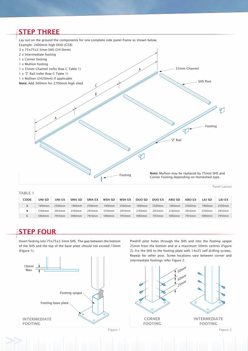
STEP THREE
STEP FOUR
Figure 1 Figure 2
Panel Layout
Lay out on the ground the components for one complete side panel frame as shown below.
Example: 2400mm high DUO (G58)
3 x 75x75x2.5mm SHS (2410mm)
2 x Intermediate footing
1 x Corner footing
1 x Mullion footing
1 x 55mm Channel (refer Row C Table 1)
1 x ‘Z’ Rail (refer Row C Table 1)
1 x Mullion (2420mm) if applicable
Note: Add 300mm for 2700mm high shed
CORNER FOOTING
INTERMEDIATE FOOTING
Insert footing into 75x75x2.5mm SHS. The gap between the bottom
of the SHS and the top of the base plate should not exceed 10mm
(Figure 1).
Predrill pilot holes through the SHS and into the footing spigot
25mm from the bottom and at a maximum 50mm centres (Figure
2). Fix the SHS to the footing plate with 14x25 self drilling screws.
Repeat for other post. Screw locations vary between corner and
intermediate footings refer Figure 2.
Note: Mullion may be replaced by 75mm SHS and Corner Footing depending on Homeshed type.
INTERMEDIATE FOOTING
Footing spigot
Footing base plate
10mmMax
55mm Channel
SHS Post
‘Z’ Rail
Footing
Footing
50mm
50mm
25mm
TABLE 1
CODE UNI SD UNI EX SMA SD SMA EX WSH SD WSH EX DUO SD DUO EX ARO SD ARO EX LKI SD LKI EX
A 1900mm 2500mm 1900mm 2500mm 1900mm 2500mm 1900mm 2500mm 1900mm 2500mm 1900mm 2500mm
B 2160mm 2910mm 2160mm 2910mm 2160mm 2910mm 2160mm 2910mm 2160mm 2910mm 2160mm 2910mm
C 5960mm 7910mm 5960mm 7910mm 5960mm 7910mm 5960mm 7910mm 5960mm 7910mm 5960mm 7910mm
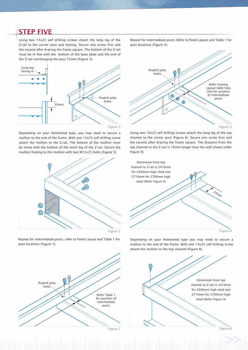
STEP FIVE
Figure 3 Figure 4
Figure 5 Figure 6
Figure 7 Figure 8
Using two 14x25 self drilling screws attach the long leg of the
Z-rail to the corner post and footing. Secure one screw first and
the second after bracing the frame square. The bottom of the Z-rail
must be in line with the bottom of the base plate and the end of
the Z-rail overhanging the post 55mm (Figure 3).
Dimension from top
channel to Z-rail is 2410mm
for 2400mm high shed and
2710mm for 2700mm high
shed (Refer Figure 9)
Refer Footing Layout table Step One for position of intermediate
posts
Long leg facing in
Depending on your Homeshed type, you may need to secure a
mullion to the end of the frame. With one 14x25 self drilling screw
attach the mullion to the Z-rail. The bottom of the mullion must
be inline with the bottom of the short leg of the Z-rail. Secure the
mullion footing to the mullion with two M12x25 bolts (Figure 5).
Using two 14x25 self drilling screws attach the long leg of the top
channel to the corner post (Figure 6). Secure one screw first and
the second after bracing the frame square. The distance from the
top channel to the Z-rail is 10mm longer than the wall sheets (refer
Figure 9).
Predrill pilot holes
55mm
Repeat for intermediate posts. Refer to Panel Layout and Table 1 for
post locations (Figure 4).
Refer Table 1for position ofintermediate
posts
Repeat for intermediate posts, refer to Panel Layout and Table 1 for
post locations (Figure 7).
Predrill pilot holes
Predrill pilot holes
Depending on your Homeshed type you may need to secure a
mullion to the end of the frame. With one 14x25 self drilling screw
attach the mullion to the top channel (Figure 8).
Dimension from top
channel to Z-rail is 2410mm
for 2400mm high shed and
2710mm for 2700mm high
shed (Refer Figure 9)
55mm
2410mmor2710mm
20mm(min)
Figure 9
Figure 10
Check Diagonal Measurements
Are Equal
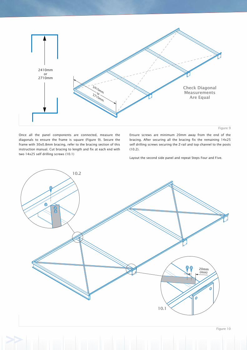
Once all the panel components are connected, measure the
diagonals to ensure the frame is square (Figure 9). Secure the
frame with 30x0.8mm bracing, refer to the bracing section of this
instruction manual. Cut bracing to length and fix at each end with
two 14x25 self drilling screws (10.1)
Ensure screws are minimum 20mm away from the end of the
bracing. After securing all the bracing fix the remaining 14x25
self drilling screws securing the Z-rail and top channel to the posts
(10.2).
Layout the second side panel and repeat Steps Four and Five.
10.1
10.2
2410mm or
2710mm
20mm70mm
70mm
60mm
20mm
All holesØ14mm
Figure 11
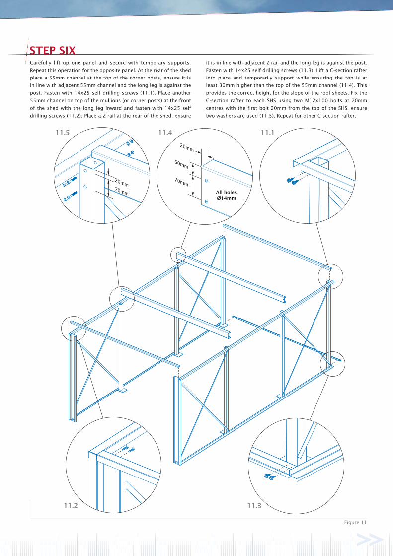
STEP SIXCarefully lift up one panel and secure with temporary supports.
Repeat this operation for the opposite panel. At the rear of the shed
place a 55mm channel at the top of the corner posts, ensure it is
in line with adjacent 55mm channel and the long leg is against the
post. Fasten with 14x25 self drilling screws (11.1). Place another
55mm channel on top of the mullions (or corner posts) at the front
of the shed with the long leg inward and fasten with 14x25 self
drilling screws (11.2). Place a Z-rail at the rear of the shed, ensure
it is in line with adjacent Z-rail and the long leg is against the post.
Fasten with 14x25 self drilling screws (11.3). Lift a C-section rafter
into place and temporarily support while ensuring the top is at
least 30mm higher than the top of the 55mm channel (11.4). This
provides the correct height for the slope of the roof sheets. Fix the
C-section rafter to each SHS using two M12x100 bolts at 70mm
centres with the first bolt 20mm from the top of the SHS, ensure
two washers are used (11.5). Repeat for other C-section rafter.
11.5 11.4 11.1
11.2 11.3
A A
B B
STEP SEVEN
Figure 12
STEP EIGHT
Figure 16
Figure 15
Figure 13 Figure 14
Predrill pilot holes
Predrill pilot holes
View from inside Homeshed
A A
B C
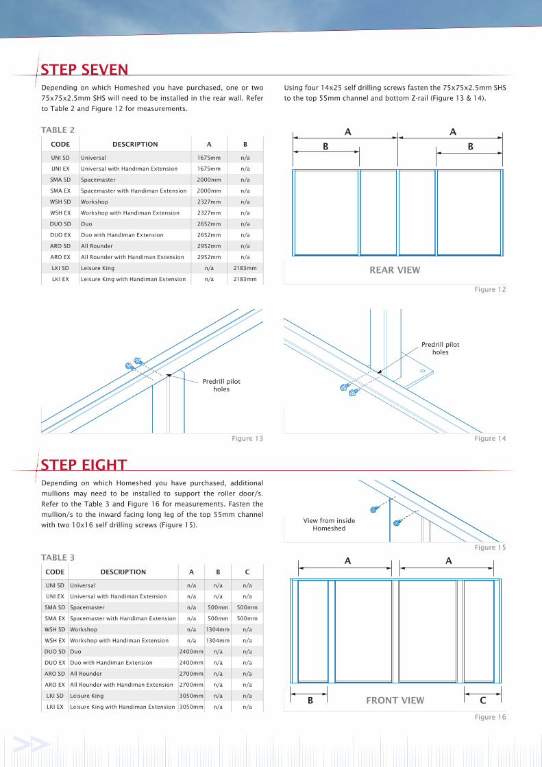
Depending on which Homeshed you have purchased, one or two
75x75x2.5mm SHS will need to be installed in the rear wall. Refer
to Table 2 and Figure 12 for measurements.
Depending on which Homeshed you have purchased, additional
mullions may need to be installed to support the roller door/s.
Refer to the Table 3 and Figure 16 for measurements. Fasten the
mullion/s to the inward facing long leg of the top 55mm channel
with two 10x16 self drilling screws (Figure 15).
FRONT VIEW
Using four 14x25 self drilling screws fasten the 75x75x2.5mm SHS
to the top 55mm channel and bottom Z-rail (Figure 13 & 14).
REAR VIEW
TABLE 2
CODE DESCRIPTION A B
UNI SD Universal 1675mm n/a
UNI EX Universal with Handiman Extension 1675mm n/a
SMA SD Spacemaster 2000mm n/a
SMA EX Spacemaster with Handiman Extension 2000mm n/a
WSH SD Workshop 2327mm n/a
WSH EX Workshop with Handiman Extension 2327mm n/a
DUO SD Duo 2652mm n/a
DUO EX Duo with Handiman Extension 2652mm n/a
ARO SD All Rounder 2952mm n/a
ARO EX All Rounder with Handiman Extension 2952mm n/a
LKI SD Leisure King n/a 2183mm
LKI EX Leisure King with Handiman Extension n/a 2183mm
TABLE 3
CODE DESCRIPTION A B C
UNI SD Universal n/a n/a n/a
UNI EX Universal with Handiman Extension n/a n/a n/a
SMA SD Spacemaster n/a 500mm 500mm
SMA EX Spacemaster with Handiman Extension n/a 500mm 500mm
WSH SD Workshop n/a 1304mm n/a
WSH EX Workshop with Handiman Extension n/a 1304mm n/a
DUO SD Duo 2400mm n/a n/a
DUO EX Duo with Handiman Extension 2400mm n/a n/a
ARO SD All Rounder 2700mm n/a n/a
ARO EX All Rounder with Handiman Extension 2700mm n/a n/a
LKI SD Leisure King 3050mm n/a n/a
LKI EX Leisure King with Handiman Extension 3050mm n/a n/a
STEP NINE
Figure 20
Figure 19
Figure 17 Figure 18
AB B
1/3
1/2
B
A
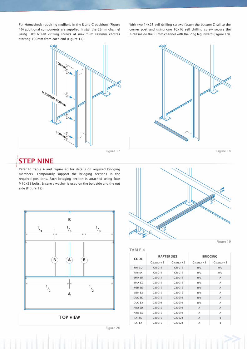
Refer to Table 4 and Figure 20 for details on required bridging
members. Temporarily support the bridging sections in the
required positions. Each bridging section is attached using four
M10x25 bolts. Ensure a washer is used on the bolt side and the nut
side (Figure 19).
TOP VIEW
For Homesheds requiring mullions in the B and C positions (Figure
16) additional components are supplied. Install the 55mm channel
using 10x16 self drilling screws at maximum 600mm centres
starting 100mm from each end (Figure 17).
With two 14x25 self drilling screws fasten the bottom Z-rail to the
corner post and using one 10x16 self drilling screw secure the
Z-rail inside the 55mm channel with the long leg inward (Figure 18).
1/2
1/3
1/3
TABLE 4
CODERAFTER SIZE BRIDGING
Category 3 Category 2 Category 3 Category 2
UNI SD C15019 C15019 n/a n/a
UNI EX C15019 C15019 n/a n/a
SMA SD C20015 C20015 n/a A
SMA EX C20015 C20015 n/a A
WSH SD C20015 C20015 n/a A
WSH EX C20015 C20015 n/a A
DUO SD C20015 C20019 n/a A
DUO EX C20019 C20019 n/a A
ARO SD C20015 C20019 A A
ARO EX C20015 C20019 A A
LKI SD C20015 C20024 A B
LKI EX C20015 C20024 A B
90mm
STEP TEN
Figure 21
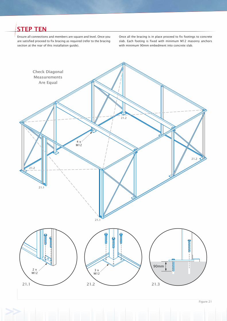
Ensure all connections and members are square and level. Once you
are satisfied proceed to fix bracing as required (refer to the bracing
section at the rear of this installation guide).
Check Diagonal
Measurements
Are Equal
2 x M12
3 x M12
4 x M12
Once all the bracing is in place proceed to fix footings to concrete
slab. Each footing is fixed with minimum M12 masonry anchors
with minimum 90mm embedment into concrete slab.
21.1 21.2 21.3
21.1
21.1
21.2
21.2
21.2
100mm
100mm
MID-HEIGHT
STEP ELEVEN
Figure 24 Figure 25
STEP TWELVE
Figure 27 Figure 28
Figure 26
Trim withtin snips
if required
Figure 22 Figure 23
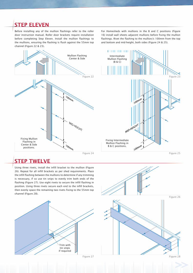
Before installing any of the mullion flashings refer to the roller
door instruction manual. Roller door brackets require installation
before completing Step Eleven. Install the mullion flashings to
the mullions, ensuring the flashing is flush against the 55mm top
channel (Figure 22 & 23).
Using three rivets, install the infill bracket to the mullion (Figure
26). Repeat for all infill brackets as per shed requirements. Place
the infill flashing between the mullions to determine if any trimming
is necessary, if so use tin snips to evenly trim both ends of the
flashing (Figure 27). Use eight rivets to secure the infill flashing in
position. Using three rivets secure each end to the infill brackets,
then evenly space the remaining two rivets fixing to the 55mm top
channel (Figure 28).
For Homesheds with mullions in the B and C positions (Figure
16) install wall sheets adjacent mullions before fixing the mullion
flashings. Rivet the flashing to the mullion/s 100mm from the top
and bottom and mid-height, both sides (Figure 24 & 25).
Mullion FlashingCenter & Side
IntermediateMullion Flashing
(B & C)
Fixing IntermediateMullion Flashing in
B & C positions.
Fixing Mullion Flashing in
Center & Sidepositions.
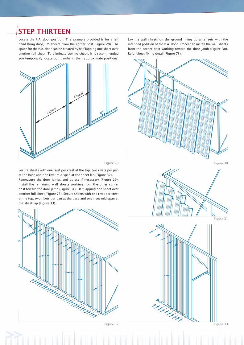
Figure 32 Figure 33
Figure 31
Figure 29 Figure 30
STEP THIRTEEN
Secure sheets with one rivet per crest at the top, two rivets per pan
at the base and one rivet mid-span at the sheet lap (Figure 32).
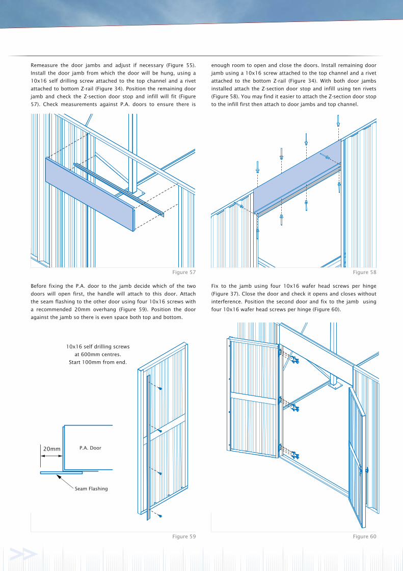
Remeasure the door jambs and adjust if necessary (Figure 29).
Install the remaining wall sheets working from the other corner
post toward the door jamb (Figure 31). Half lapping one sheet over
another full sheet (Figure 73). Secure sheets with one rivet per crest
at the top, two rivets per pan at the base and one rivet mid-span at
the sheet lap (Figure 33).
Locate the P.A. door position. The example provided is for a left
hand hung door, 1½ sheets from the corner post (Figure 29). The
space for the P.A. door can be created by half lapping one sheet over
another full sheet. To eliminate cutting sheets it is recommended
you temporarily locate both jambs in their approximate positions.
Lay the wall sheets on the ground lining up all sheets with the
intended position of the P.A. door. Proceed to install the wall sheets
from the corner post working toward the door jamb (Figure 30).
Refer sheet fixing detail (Figure 73).
STEP FOURTEEN
Figure 34 Figure 35
Figure 36 Figure 37
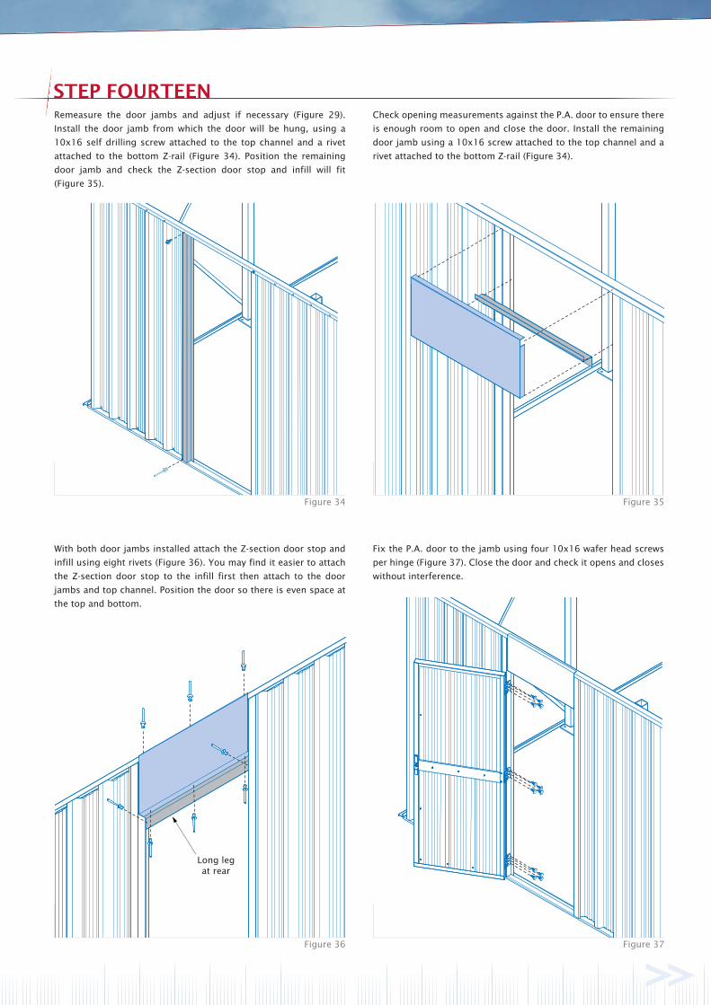
Long legat rear
Remeasure the door jambs and adjust if necessary (Figure 29).
Install the door jamb from which the door will be hung, using a
10x16 self drilling screw attached to the top channel and a rivet
attached to the bottom Z-rail (Figure 34). Position the remaining
door jamb and check the Z-section door stop and infill will fit
(Figure 35).
Check opening measurements against the P.A. door to ensure there
is enough room to open and close the door. Install the remaining
door jamb using a 10x16 screw attached to the top channel and a
rivet attached to the bottom Z-rail (Figure 34).
With both door jambs installed attach the Z-section door stop and
infill using eight rivets (Figure 36). You may find it easier to attach
the Z-section door stop to the infill first then attach to the door
jambs and top channel. Position the door so there is even space at
the top and bottom.
Fix the P.A. door to the jamb using four 10x16 wafer head screws
per hinge (Figure 37). Close the door and check it opens and closes
without interference.
Trim withtin snips
if required
STEP FIFTEEN
Figure 38
STEP SIXTEEN
Figure 39
Figure 40 Figure 41
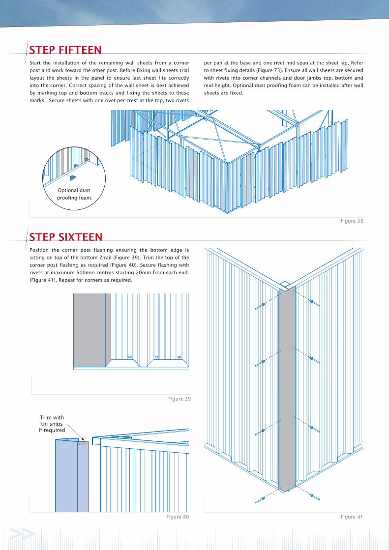
Start the installation of the remaining wall sheets from a corner
post and work toward the other post. Before fixing wall sheets trial
layout the sheets in the panel to ensure last sheet fits correctly
into the corner. Correct spacing of the wall sheet is best achieved
by marking top and bottom tracks and fixing the sheets to these
marks. Secure sheets with one rivet per crest at the top, two rivets
Position the corner post flashing ensuring the bottom edge is
sitting on top of the bottom Z-rail (Figure 39). Trim the top of the
corner post flashing as required (Figure 40). Secure flashing with
rivets at maximum 500mm centres starting 20mm from each end.
(Figure 41). Repeat for corners as required.
per pan at the base and one rivet mid-span at the sheet lap. Refer
to sheet fixing details (Figure 73). Ensure all wall sheets are secured
with rivets into corner channels and door jambs top, bottom and
mid-height. Optional dust proofing foam can be installed after wall
sheets are fixed.
Optional dust
proofing foam.
STEP SEVENTEEN
Figure 42
Figure 44
Figure 43
STEP EIGHTEEN
Figure 45
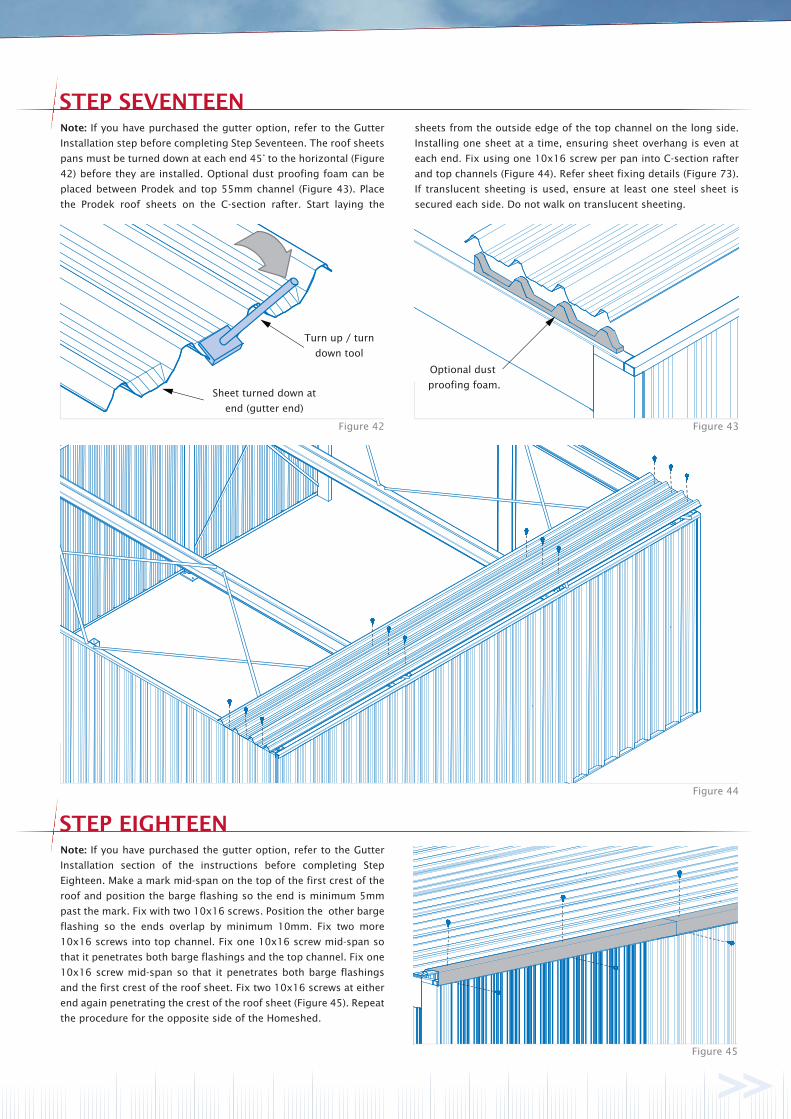
Note: If you have purchased the gutter option, refer to the Gutter
Installation step before completing Step Seventeen. The roof sheets
pans must be turned down at each end 45° to the horizontal (Figure
42) before they are installed. Optional dust proofing foam can be
placed between Prodek and top 55mm channel (Figure 43). Place
the Prodek roof sheets on the C-section rafter. Start laying the
sheets from the outside edge of the top channel on the long side.
Installing one sheet at a time, ensuring sheet overhang is even at
each end. Fix using one 10x16 screw per pan into C-section rafter
and top channels (Figure 44). Refer sheet fixing details (Figure 73).
If translucent sheeting is used, ensure at least one steel sheet is
secured each side. Do not walk on translucent sheeting.
Sheet turned down at
end (gutter end)
Turn up / turn
down tool
Optional dust
proofing foam.
Note: If you have purchased the gutter option, refer to the Gutter
Installation section of the instructions before completing Step
Eighteen. Make a mark mid-span on the top of the first crest of the
roof and position the barge flashing so the end is minimum 5mm
past the mark. Fix with two 10x16 screws. Position the other barge
flashing so the ends overlap by minimum 10mm. Fix two more
10x16 screws into top channel. Fix one 10x16 screw mid-span so
that it penetrates both barge flashings and the top channel. Fix one
10x16 screw mid-span so that it penetrates both barge flashings
and the first crest of the roof sheet. Fix two 10x16 screws at either
end again penetrating the crest of the roof sheet (Figure 45). Repeat
the procedure for the opposite side of the Homeshed.
GUTTER INSTALLATION
Figure 47 Figure 48
Figure 49 Figure 50
Figure 51 Figure 52
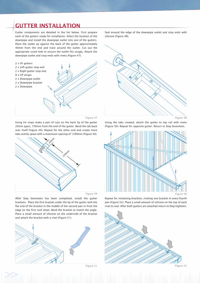
Gutter components are detailed in the list below. First prepare
each of the gutters ready for installation. Select the location of the
downpipe and install the downpipe outlet into one of the gutters.
Place the outlet up against the back of the gutter approximately
40mm from the end and trace around the outlet. Cut out the
appropriate sized hole to ensure the outlet fits snugly. Attach the
downpipe outlet and stop ends with rivets (Figure 47).
Seal around the edge of the downpipe outlet and stop ends with
silicone (Figure 48).
Using tin snips make a pair of cuts on the back lip of the gutter
20mm apart, 150mm from the end of the gutter. Bend the tab back
over itself (Figure 49). Repeat for the other end and create more
tabs evenly space with a maximum spacing of 1200mm (Figure 50).
Using the tabs created, attach the gutter to top rail with rivets
(Figure 50). Repeat for opposite gutter. Return to Step Seventeen.
After Step Seventeen has been completed, install the gutter
brackets. Place the first bracket under the lip of the gutter with the
flat end of the bracket in the middle of the second pan in from the
edge on the first roof sheet. Bend the bracket to match the angle.
Place a small amount of silicone on the underside of the bracket
and attach the bracket with a rivet (Figure 51).
Repeat for remaining brackets, riveting one bracket in every fourth
pan (Figure 52). Place a small amount of silicone on the top of each
rivet to seal. After both gutters are attached return to Step Eighteen.
2 x VF gutters
2 x Left gutter stop end
2 x Right gutter stop end
8 x GP straps
2 x Downpipe outlet
2 x Downpipe bracket
2 x Downpipe
20m
m
150m
m
ROLLER DOOR
DOUBLE PA DOOR OPTION
DOWNPIPE INSTALLATION
Figure 53 Figure 54
Figure 55 Figure 56
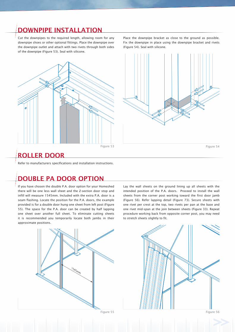
Refer to manufacturers specifications and installation instructions.
If you have chosen the double P.A. door option for your Homeshed
there will be one less wall sheet and the Z-section door stop and
infill will measure 1545mm. Included with the extra P.A. door is a
seam flashing. Locate the position for the P.A. doors, the example
provided is for a double door hung one sheet from left post (Figure
55). The space for the P.A. door can be created by half lapping
one sheet over another full sheet. To eliminate cutting sheets
it is recommended you temporarily locate both jambs in their
approximate positions.
Lay the wall sheets on the ground lining up all sheets with the
intended position of the P.A. doors. Proceed to install the wall
sheets from the corner post working toward the first door jamb
(Figure 56). Refer lapping detail (Figure 73). Secure sheets with
one rivet per crest at the top, two rivets per pan at the base and
one rivet mid-span at the join between sheets (Figure 33). Repeat
procedure working back from opposite corner post, you may need
to stretch sheets slightly to fit.
Cut the downpipes to the required length, allowing room for any
downpipe shoes or other optional fittings. Place the downpipe over
the downpipe outlet and attach with two rivets through both sides
of the downpipe (Figure 53). Seal with silicone.
Place the downpipe bracket as close to the ground as possible.
Fix the downpipe in place using the downpipe bracket and rivets
(Figure 54). Seal with silicone.
20mm
Figure 57 Figure 58
Figure 59 Figure 60
Before fixing the P.A. door to the jamb decide which of the two
doors will open first, the handle will attach to this door. Attach
the seam flashing to the other door using four 10x16 screws with
a recommended 20mm overhang (Figure 59). Position the door
against the jamb so there is even space both top and bottom.
Fix to the jamb using four 10x16 wafer head screws per hinge
(Figure 37). Close the door and check it opens and closes without
interference. Position the second door and fix to the jamb using
four 10x16 wafer head screws per hinge (Figure 60).
10x16 self drilling screws
at 600mm centres.
Start 100mm from end.
Remeasure the door jambs and adjust if necessary (Figure 55).
Install the door jamb from which the door will be hung, using a
10x16 self drilling screw attached to the top channel and a rivet
attached to bottom Z-rail (Figure 34). Position the remaining door
jamb and check the Z-section door stop and infill will fit (Figure
57). Check measurements against P.A. doors to ensure there is
enough room to open and close the doors. Install remaining door
jamb using a 10x16 screw attached to the top channel and a rivet
attached to the bottom Z-rail (Figure 34). With both door jambs
installed attach the Z-section door stop and infill using ten rivets
(Figure 58). You may find it easier to attach the Z-section door stop
to the infill first then attach to door jambs and top channel.
P.A. Door
Seam Flashing

LOUVRED WINDOW OPTION
Figure 62 Figure 64
Figure 61 Figure 62
If you have chosen the louvred window option for your Homeshed,
one of the wall sheets will need to be trimmed to suit with tin snips.
The example provide is for a window one sheet from the corner
post on the short side of the shed 500mm from top channel.
Fix one full length wall sheet against the corner post. Then fix the
larger trimmed sheet (Figure 61) as previously described (Figure
73). Place the remaining trimmed sheet loosely into position and
check to see that the window will fit the opening (Figure 62).
Ensure the wall sheets either side of the window tightly abutt
the frame so no gaps occur. Correct spacing of the sheet is best
achieved by marking the sheet location on the top and bottom
tracks and fixing the sheets to these marks. Fix the remaining
sheets working back from the corner post (Figure 62).
Place the pre-assembled louvred window and remaining trimmed
sheet into the opening. Check for squareness. Install with rivets
securing the window frame to the crests of the wall sheets and
evenly spaced around the remaining frame (Figure 64). Place a bead
of silicone in each corner of the window to prevent water entry.
SLIDING WINDOW OPTION
Figure 65 Figure 66
Figure 67 Figure 68
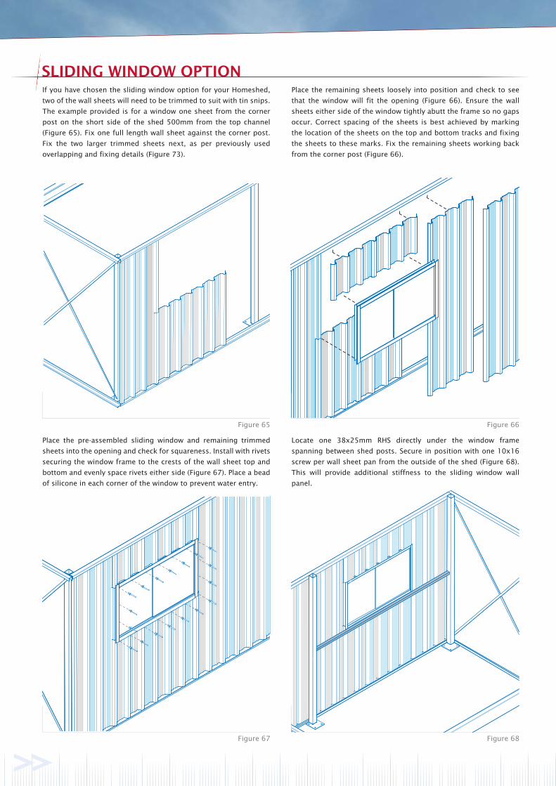
If you have chosen the sliding window option for your Homeshed,
two of the wall sheets will need to be trimmed to suit with tin snips.
The example provided is for a window one sheet from the corner
post on the short side of the shed 500mm from the top channel
(Figure 65). Fix one full length wall sheet against the corner post.
Fix the two larger trimmed sheets next, as per previously used
overlapping and fixing details (Figure 73).
Place the pre-assembled sliding window and remaining trimmed
sheets into the opening and check for squareness. Install with rivets
securing the window frame to the crests of the wall sheet top and
bottom and evenly space rivets either side (Figure 67). Place a bead
of silicone in each corner of the window to prevent water entry.
Place the remaining sheets loosely into position and check to see
that the window will fit the opening (Figure 66). Ensure the wall
sheets either side of the window tightly abutt the frame so no gaps
occur. Correct spacing of the sheets is best achieved by marking
the location of the sheets on the top and bottom tracks and fixing
the sheets to these marks. Fix the remaining sheets working back
from the corner post (Figure 66).
Locate one 38x25mm RHS directly under the window frame
spanning between shed posts. Secure in position with one 10x16
screw per wall sheet pan from the outside of the shed (Figure 68).
This will provide additional stiffness to the sliding window wall
panel.
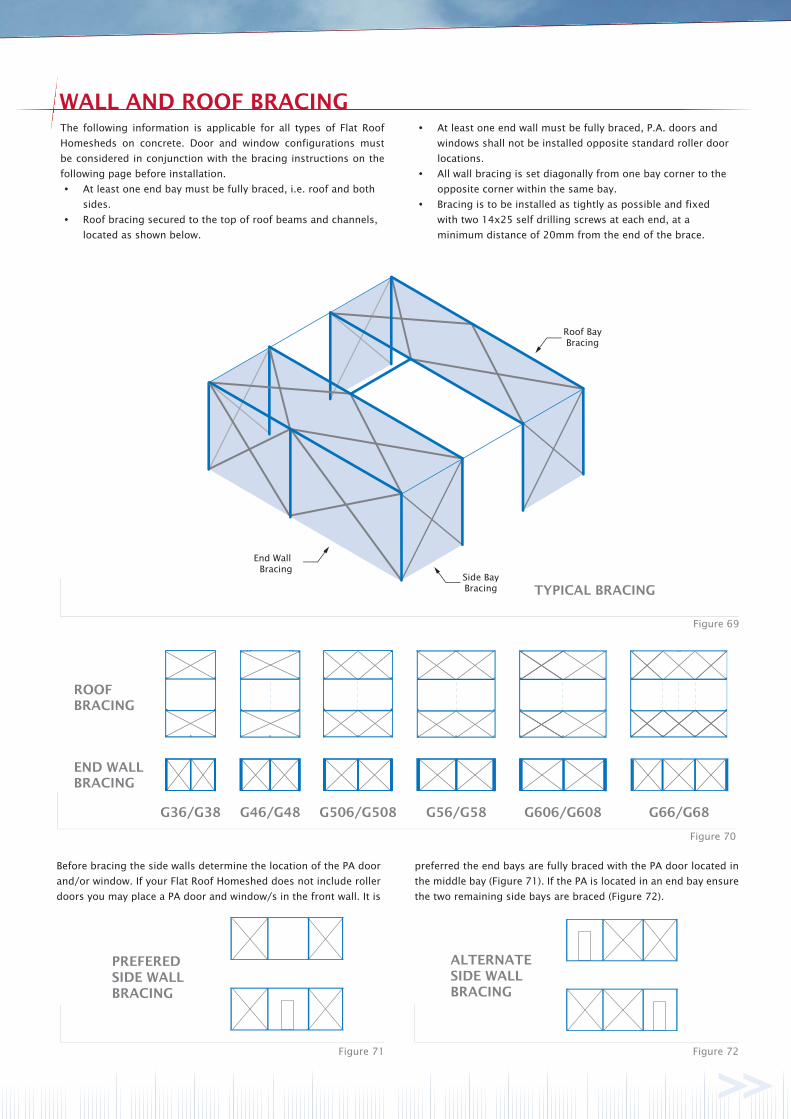
End Wall Bracing
Roof Bay Bracing
Side Bay Bracing TYPICAL BRACING
G36/G38 G46/G48 G506/G508 G56/G58 G606/G608 G66/G68
ROOFBRACING
END WALLBRACING
WALL AND ROOF BRACING
Figure 71 Figure 72
Figure 70
Figure 69
The following information is applicable for all types of Flat Roof
Homesheds on concrete. Door and window configurations must
be considered in conjunction with the bracing instructions on the
following page before installation.
At least one end bay must be fully braced, i.e. roof and both
sides.
Roof bracing secured to the top of roof beams and channels,
located as shown below.
At least one end wall must be fully braced, P.A. doors and
windows shall not be installed opposite standard roller door
locations.
All wall bracing is set diagonally from one bay corner to the
opposite corner within the same bay.
Bracing is to be installed as tightly as possible and fixed
with two 14x25 self drilling screws at each end, at a
minimum distance of 20mm from the end of the brace.
Before bracing the side walls determine the location of the PA door
and/or window. If your Flat Roof Homeshed does not include roller
doors you may place a PA door and window/s in the front wall. It is
PREFEREDSIDE WALLBRACING
ALTERNATESIDE WALLBRACING
preferred the end bays are fully braced with the PA door located in
the middle bay (Figure 71). If the PA is located in an end bay ensure
the two remaining side bays are braced (Figure 72).
MAINTENANCE
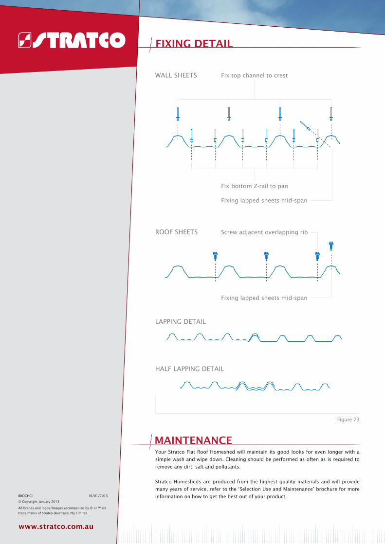
LAPPING DETAIL
HALF LAPPING DETAIL
FIXING DETAIL
Figure 73
Fixing lapped sheets mid-span
Fix top channel to crest
Fix bottom Z-rail to pan
Fixing lapped sheets mid-span
Screw adjacent overlapping rib
WALL SHEETS
ROOF SHEETS
Your Stratco Flat Roof Homeshed will maintain its good looks for even longer with a
simple wash and wipe down. Cleaning should be performed as often as is required to
remove any dirt, salt and pollutants.
Stratco Homesheds are produced from the highest quality materials and will provide
many years of service, refer to the ‘Selection Use and Maintenance’ brochure for more
information on how to get the best out of your product.BROCHCI 16/01/2013
© Copyright January 2013