Embed Size (px)
DESCRIPTION
Correlaciones para el cálculo de radiación en el Flare
Citation preview

7/17/2019 Flare Systems
http://slidepdf.com/reader/full/flare-systems-568f385db390e 1/93
EDS 2004/Flare Systems-1
Flare Systems
Training Services
Flaring is a volatile organic compound (VOC) combustion control process in which
the VOCs are piped to a remote, usually elevated, location and burned in the open
air using a specially designed burner tip, auxiliary fuel, and steam or air to promote
mixing for nearly complete (>98 percent) VOC destruction. Completeness of
combustion in a flare is governed by flame temperature, residence time in the
combustion zone, turbulent mixing of the components to complete the oxidation
reaction, and available oxygen for free radical formation. Combustion is complete
if all VOCs are converted to carbon dioxide and water. Incomplete combustion
results in some of the VOC being unaltered or converted to other organic
compounds such as aldehydes or acids.
Flares are generally categorized in two ways: (1) by the height of the flare tip (i.e.
ground or elevated); and (2) by the method of enhancing mixing at the flare tip (i.e.
steam-assisted, air-assisted, pressure-assisted, or non-assisted). Elevating the flarecan prevent potentially dangerous conditions at ground level where the open flame
(i.e. an ignition source) is located near a process unit. Further, the products of
combustion can be dispersed above working areas to reduce the effects of noise,
heat, smoke, and objectionable odors.
The primary function of a flare is to dispose of toxic, corrosive, or flammable vapor
safely, under relief conditions, by converting them to less objectionable products by
combustion.

7/17/2019 Flare Systems
http://slidepdf.com/reader/full/flare-systems-568f385db390e 2/93
EDS 2004/Flare Systems-2
Table of Contents
Flare Systems
– Purpose
– Flare selection
– Support structures
– Combustion theory
– Radiation theory
– Regulatory compliance
– Equipment design – Flare design requirements
– Incineration
Flare operation and design have become more complicated than simply burning
waste gas. The major components of any flare facility are the knockout drum, flare
stack, continuous purge gas, flare tip and ignition system. Normally the flare
system will use some additional utilities such as steam or air to make the flare
smokeless. In designing a flare, considerable effort should be devoted to meeting
the prime objective, which is the safe disposal of waste gas. The overall
characteristic of the flame is a function of many variables, such as exit velocity of
the gas, air-to-gas ration, wind speed, gas composition and flame temperature.
Almost 35% of the flare design depends on the heat radiated by the flame. The less
heat radiated, the more desirable the flare. The major sources of thermal radiation
are free carbon, water vapor and carbon dioxide, but the principal source of these
three are fee carbon. Free carbon is formed from the pyrolysis of the hydrocarbon
gas. Noise is another type of environmental pollution. There are two types of noise
emitted by the flare. Normal noise amounts mainly form the gas combustion, thesecond type is shock noise generated by the gas velocity gets. In any flare system,
waste gas shall be sent to a knockout drum to knockout any hydrocarbon
condensate.
As shown in the table of contents, we will be covering a wide range of topics of
flare systems.

7/17/2019 Flare Systems
http://slidepdf.com/reader/full/flare-systems-568f385db390e 3/93
EDS 2004/Flare Systems-3
Disposal System
Disposal of vapors and
liquids discharged
Types of Systems
Open System
– Discharge directly to
atmosphere
Closed System
– Discharge to a collection
header – Dispose to a flare
Line sizing for relief and flare headers requires the use of compressible flow
equations. UOP has developed a computer program for this purpose. The
calculation method usually starts at the flare itself where the outlet pressure is
atmospheric. The program uses design flows through the system (typically the
general electrical power failure case). Flare tip velocities are designed up to 0.5
MACH and, therefore, a pressure drop can be determined. The pressure drop
through the water seal, molecular seal, and knockout drum must also be included.
The next step is to determine the equivalent lengths of the piping this requires one
to determine the strength length of pipe, elbows, and other fittings. Try to limit the
velocity throughout the system to 0.7 MACH. Never exceed MACH since this will
cause a discontinuity in the flow pressure drop and a lot of noise. Next, the
properties will best estimated for MW = W/(MW/W), for temperature T = WT/W.
Next, the inlet pressure for each section is calculated by knowing the pressure drop
for that section.
One must continue calculations back to the relief valve. Next, one needs to check to
see if the allowable pressure is less than the actual pressure if not then one will have
to increase the relief header size to reduce pressure drop in the system. The
equations used assume isothermal flows in the relief header. This is adequate and
conservative for most applications. There are only a number of relief systems that
are allowed to atmosphere directly.
7/17/2019 Flare Systems
http://slidepdf.com/reader/full/flare-systems-568f385db390e 4/93
EDS 2004/Flare Systems-4
Typical Relief System
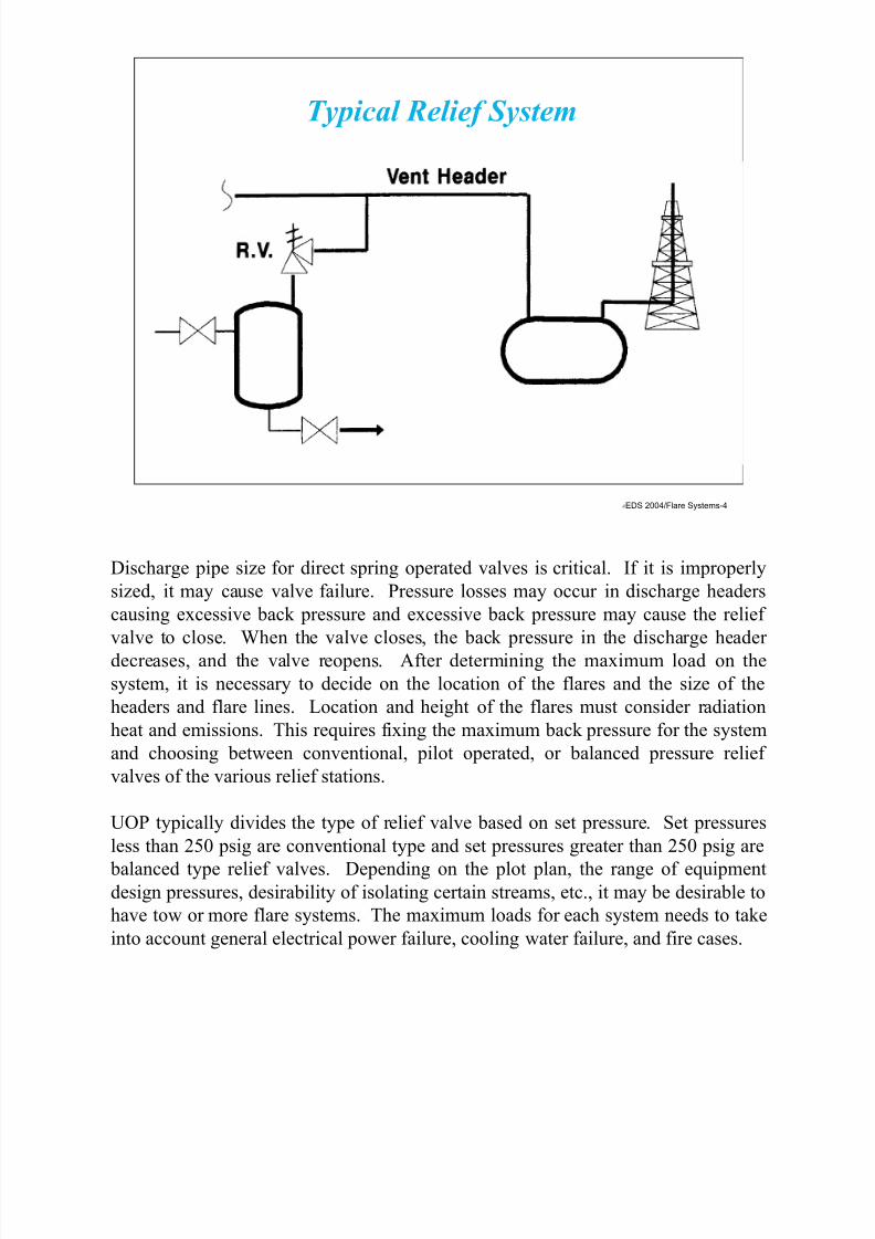
Discharge pipe size for direct spring operated valves is critical. If it is improperly
sized, it may cause valve failure. Pressure losses may occur in discharge headers
causing excessive back pressure and excessive back pressure may cause the relief
valve to close. When the valve closes, the back pressure in the discharge header
decreases, and the valve reopens. After determining the maximum load on the
system, it is necessary to decide on the location of the flares and the size of the
headers and flare lines. Location and height of the flares must consider radiation
heat and emissions. This requires fixing the maximum back pressure for the system
and choosing between conventional, pilot operated, or balanced pressure relief
valves of the various relief stations.
UOP typically divides the type of relief valve based on set pressure. Set pressures
less than 250 psig are conventional type and set pressures greater than 250 psig are
balanced type relief valves. Depending on the plot plan, the range of equipmentdesign pressures, desirability of isolating certain streams, etc., it may be desirable to
have tow or more flare systems. The maximum loads for each system needs to take
into account general electrical power failure, cooling water failure, and fire cases.

7/17/2019 Flare Systems
http://slidepdf.com/reader/full/flare-systems-568f385db390e 5/93
EDS 2004/Flare Systems-5
Relief Header Sizing - Equations to Use
V = M * SV / A / 60
SV = 379.5/MW * (14.7/(Pout+14.7)*((460+T)/520)))
SonicV = 60 * (32.17*1.1*1546*(460+T)/MW)^0.5
MACH = V/SonicV
V = velocity in ft/min
M = flowrate in lb/hr
SV = specific volume in ft3/lb
A= pipe area in ft2
MW = molecular weight
Pout = outlet pressure in psig T = temperature in F
SonicV = Sonic Velocity in ft/min
Relief header sizing is a very calculation intensive. The two main criteria used in
sizing relief headers is to keep the velocity below 0.7 MACH in any segment and to
limit the velocity at the flare tip to 0.5 MACH. The second main requirement is to
maintain the pressure in the header below the maximum allowable pressure for the
relief valves.

7/17/2019 Flare Systems
http://slidepdf.com/reader/full/flare-systems-568f385db390e 6/93
EDS 2004/Flare Systems-6
Step 1: Start at flare tip and calculate the pressure drop
across the flare tip at 0.5 MACH
Step 2: Determine equivalent lengths for all segments
Step 3: Limit relief header velocity to less than 0.7 MACH
Step 4: Establish properties of the gases
T=Σ(wi*Ti)/Σwi where T=temp and w is flowrate lb/hr
MW = Σwi/Σ(wi/MWi) where MW is Molecular Weight
Step 5: Calculate pressure drop
Step 6: Review allowable pressure against actual pressure for
each segment Step 7: Review velocity is below 0.7 MACH in each segment
Relief Header Sizing - 7 Steps
The above slide describes the seven steps to relief header sizing. When the
maximum vapor relieving requirement of the flare system has been established and
the maximum allowable back pressure has been defined, line sizing reduces to
standard flow calculations.
Since vapors in the flare headers are relieved from a high pressure system to almost
atmospheric pressure, there is an appreciable kinetic energy change throughout the
pipeline. The flow condition is that of compressible flow. The nature of
compressible flow in the case of flare headers may be assumed to be isothermal
since flare lines are normally long and not fully insulated.

7/17/2019 Flare Systems
http://slidepdf.com/reader/full/flare-systems-568f385db390e 7/93
EDS 2004/Flare Systems-7
Purpose of Flare
Define Loadings to be Handled
– Calculate loadings for all
contingencies
– Geographic location of each
source
– Calculate maximum load
(power failure,fire case)
• Fire case limited to a
ground area of 230 - 460
square meters
• Calculate maximum back
pressure
Selection of a disposal method is subjected to many factors such as the geographic
location of each source, maximum loading for each case (i.e. General Electrical
Power Failure, Cooling Water Failure Case, etc.). The purpose of the flare and
relieving system is to conduct the relieved fluids to a location where it can be safety
discharged and burned.
The disposal system of flares consist of the relief valves, piping, drums and some
type of combustion system. In the past, many relief valves were discharge directly
to the atmosphere. This is still acceptable if environmental regulations permit such
discharges. Therefore, most steam relief valves or ones containing air are relieved
directly to the atmosphere. The relieving vapors from different relief valves and
control valves are normally collected in individual relief subheaders located near
each process area. These headers are interconnected and lead to localized knockout
drums.

7/17/2019 Flare Systems
http://slidepdf.com/reader/full/flare-systems-568f385db390e 8/93
EDS 2004/Flare Systems-8
Major Factors Influencing Flare Design
Gas Composition
Flow Rate Gas Pressure Available
Initial Investment
Operating Costs
Gas Temperature
Energy Availability
Environmental
Requirements
Safety Requirements
Social Requirements
Flaring is a volatile organic compound (VOC) combustion control process in which
the VOCs are piped to a remote, usually elevated, location and burned in an open
flame in the open air using a specially designed burner tip, auxiliary fuel, and steam
or air to promote mixing for nearly completed (>98 percent) VOC destruction.
Completeness of combustion in a flare is governed by flame temperature, residence
time in the combustion zone, turbulent mixing of the components to complete the
oxidation reaction, and available oxygen for free radical formation. Combustion is
complete if all VOCs are converted to carbon dioxide and water. Incomplete
combustion results in some of the VOC being unaltered or converted to other
organic compounds such as aldehydes or acids. The flaring process can produce
some undesirable by-products including noise, smoke, heat radiation, light, Sox,
NOx, CO, and an additional source of ignition where not desired. However, by
proper design, these can be minimized.
Major factors influencing flare design include gas composition, flow rate, gas
pressure available, initial cost, operating costs, gas temperature, energy availability,
environmental regulations, safety requirements and social requirements. The single
largest factor depends on the site. In the United States, environmental requirements
drive what, if any, type of flare can be installed.

7/17/2019 Flare Systems
http://slidepdf.com/reader/full/flare-systems-568f385db390e 9/93
EDS 2004/Flare Systems-9
Elevated Flare System
TI LGR
PI
LIAH
PI
ROROEmergencyGas Purge
NormalGas Purge
Purge GasPressure Relief
From Process Units
Steam
Slop To
Slop Tank
PIPC
FuelGas
Gas ToPilot
Grade
Flare Tip
Dry
Seal
FlareStack
Steam Ring
PlantAir
Knockout DrumPumpout Pump
Flare Knockout Drum
Pilot IgnitionSystems Locate
At Flare Knockout Drum
SolenoidValve
(With ManualReset)
Vent
Instrument
Air
Switch
TAH
M
The above drawing is the typical elevated flare system one finds in a refinery. The
relief valves are collected from the process units and are sent to a flare knockout
drum. In the knockout drum, the liquid is removed and the gases are sent to the
flare. The flare is elevated in this case to keep all the burning occurring above the
ground level where radiation and toxic compounds may collect.
At the top of the flare is the flare tip where all of the burning occurs. The steam
ring is shown for smokeless operation, otherwise there would be a lot of smoking
occurring. The dry stack is provide to reduce the purge gas required. Purge gas are
required to maintain a positive pressure in the flare system. If there was not a
positive pressure in the flare system, then a vacuum condition might occur and air
could get into the system. Air is not wanted in the system because an explosive
condition might occur in the header.
In the flare knockout drum, the liquids are separated and collected. Since there is
some value to the liquid, the liquid is normally sent to either the slop oil tank or to
the crude oil tanks for reprocessing. The pilot ignition system is used to keep fuel
gas supply to the pilots and the flame front generator is used to light the pilots.

7/17/2019 Flare Systems
http://slidepdf.com/reader/full/flare-systems-568f385db390e 10/93
EDS 2004/Flare Systems-10
Elevated Flare System(Knockout Pot in Stack)
FS-R00-02
The above drawing shows and elevated flare system with the knockout drum in the
flare stack. The advantage of this scheme is that it takes up less plot space. In
addition, the knockout drum and the flare stack/tip can be all produced by one
vendor. The disadvantage of the knockout drum in the stack is that the flowrate of
the flare gas is limited because of the limited knockout drum cross-sectional area.
The stack is also limited to a self-supporting type or a derrick type.
The emergency gas purge allows for addition fuel gas to be injected into the relief
header during an upset condition. The emergency gas purge is required if a very hot
release happens. This is because after the release the volume in the knockout drum
and the relief header will decrease because of the cooling occurring in the lines.
Therefore, the emergency gas purge needs to be designed to handle the cool down
of the gases say from 500°F to 100°F in a one hour time period.

7/17/2019 Flare Systems
http://slidepdf.com/reader/full/flare-systems-568f385db390e 11/93
EDS 2004/Flare Systems-11
Elevated Flare System(Water Seal and Knockout Pot in Stack)
Title Guide
EmergencyGas Purge
NormalGas Purge
PurgeGas
Pressure Relief From Process Units
Steam
Gas ToPilot Grade
FlareStack
LGR
LIAHPI
RORO
PI
PC
FuelGas
Knockout DrumPumpout Pump
Flare Tip
PlantAir
Flare Knockout DrumAnd Water Seal
Water Seal
Water
Pilot IgnitionSystems Locate At
Flare Knockout DrumSlop toSlop Tank
MSolenoid
Valve
(With Manual
Reset)
Vent
Instrument
Air
Switch
TAH
Steam Ring
The above drawing in an elevated flare system with the knockout drum and the
water seal within the flare stack. The water seal is a critical part of the flare system
because it provides a flash back protection in the system. In addition, since the inlet
gas pipe discharges into the water seal at approximately 4 inches below the top of
the water, a back pressure is produced in the relief header and therefore a positive
pressure will be produced in the flare system.
The seal drum can also be used to set up a simple staging system for burners. The
water holdup should be sufficient to provide a 10-foot slug of water in the inlet line
to the drum if an explosion occurs downstream of the drum.
A seal dam is normally provided in each drum to prevent the burner back pressure
from varying the seal level. The seal loops from the drum to the sewer should
provide a seal depth of at least 10 feet. Each drum is provided with a seal water rateof approximately 25 gpm.
The sumerged ends of the inlet lines to the drums are notched to prevent cyclic
release of the gas which accumulates from normal leakage.

7/17/2019 Flare Systems
http://slidepdf.com/reader/full/flare-systems-568f385db390e 12/93
EDS 2004/Flare Systems-12
Ground Flare System
FS-R00-05
EmergencyGas Purge
NormalGas Purge
Purge Gas Pressure Relief
From Process UnitsSlop To
Slop Tank
Grade
TI LGR
PI
LIAH
PI
M
POPO
MainHeader
PI
PC
PlantAir
Gas ToPilot
StageHeader
FuelGas
PC
Burners
Ground FlareRetention Dike
Knockout DrumPumpout PumpFlare Knockout Drum
Pilot IgnitionSystems Locate At
Flare Knockout Drum
SolenoidValve
(With ManualReset)
Vent
InstrumentAir
Switch
The above drawing shows a ground flare installed in Mexico. As one can see from
the photograph, the ground flare is installed in a dike enclosure. The person shown
is on top of the dike and is feeling the effects of the radiation. The ground flare in
the photo is at peak rate as can one can see from the total number of burners in
operation.
The ground flare system is different from the elevated flare system in a number of
important areas. One naturally is that the ground flare is located at grade and the
elevated flare is located some distance above grade. The second difference is that
the ground flare requires more pressure at the burner tip. While the elevated flare
system requires only about 1 psi at the flare tip for pressure drop reasons, the
ground flare requires 7 to 10 psi at the burner tip. The high pressure required is that
a ground flare does not require steam to make it smokeless. The ground flare is
smokeless because of the higher pressure at the burner tip causes a lot of turbulenceat the burner tip. This turbulence causes the air and fuel to mix extremely well to
produce a clean burning flame.

7/17/2019 Flare Systems
http://slidepdf.com/reader/full/flare-systems-568f385db390e 13/93
EDS 2004/Flare Systems-13
Two Stage Flare System(Elevated/Ground)
FS-R00-06
EmergencyGas Purge
NormalGas Purge
Purge Gas Pressure Relief From Process Units
Slop ToSlop Tank
Grade
Water
Seal
PlantAir
Gas ToPilot
Fuel
Gas
Knockout Drum
Pumpout PumpFlare Knockout Drum
TI LGR
PI
LIAH
PI
M
RORO
Water
PI
PC
Seal
Flare
Stack
FlareTip
EnclosedGroundPlane
Pilot IgnitionSystems Locate At
Flare Knockout Drum
SolenoidValve
(With ManualReset)
Vent
InstrumentAir
Switch
The above photograph shows a two stage flare system. The first stage is the
enclosed ground flare and the second stage is the elevated flare system. The
advantage of this two stage flare system is that the main flaring can take place in the
enclosed ground flare. In this manner, neighbors and people within the refinery are
usually not aware that the refinery is burning any material. This is highly
advantageous for social reasons, environmental reasons, and safety reasons.
The two stage system works by the principle of using two water seals. The water
seal for then enclosed ground flare is typically set at about 4 inches of water column
and the water seal for the elevated flare is set at about 10 inches of water column.
Therefore, the normal flowrate of flare gases is to the enclosed ground flare because
of the lower pressure drop in that system. When the flow rate becomes large, the
pressure drop of 10 inches is exceeded and the flow goes both to the enclosed
ground flare and to the elevated flare.

7/17/2019 Flare Systems
http://slidepdf.com/reader/full/flare-systems-568f385db390e 14/93
EDS 2004/Flare Systems-14
Two Stage Flare System
FS-R00-04
The above drawing shows a two stage flare system which utilizes an air assisted
flare for the first stage and the elevated emergency flare for the second stage. The
advantage of this system is cost compared to the two stage system which utilizes the
enclosed flare. The operation is similar to the two stage flare system which utilizes
the enclosed ground flare.
The main flare flow gases will go to the elevated air-assisted flare by means of the
water seal. The water seal will be utilized only for the elevated emergency gas
flare. The air-assisted flare will be not utilizing the water seal and the flow of flare
gas will go directly to that flare. Once the water seal differential is exceeded in
pressure drop, the emergency gas flare will open to allow both flare to be in
operation during peak flow rates.
The advantage of this system is that the main burning of flare gases occurs in theair-assisted flare and not the emergency flare. Large diameter flares (such as the
emergency gas flare above) have a difficult time burning low flows. The low flow
results in burning inside the flare tip which can result in premature failure of the tip.
By allowing the main burning to occur in the small diameter air-assisted flare,
premature failure of the tip normally does not occur.
7/17/2019 Flare Systems
http://slidepdf.com/reader/full/flare-systems-568f385db390e 15/93
EDS 2004/Flare Systems-15
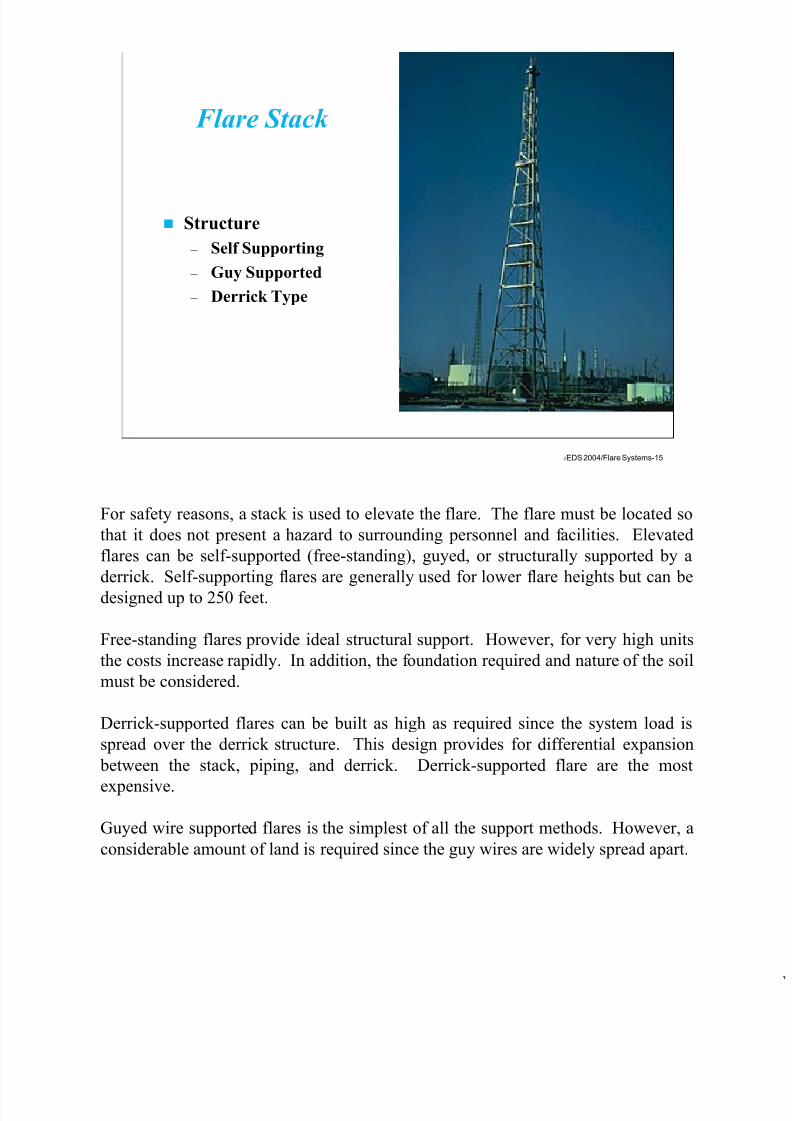
Flare Stack
Structure
– Self Supporting
– Guy Supported
– Derrick Type
For safety reasons, a stack is used to elevate the flare. The flare must be located so
that it does not present a hazard to surrounding personnel and facilities. Elevated
flares can be self-supported (free-standing), guyed, or structurally supported by a
derrick. Self-supporting flares are generally used for lower flare heights but can be
designed up to 250 feet.
Free-standing flares provide ideal structural support. However, for very high units
the costs increase rapidly. In addition, the foundation required and nature of the soil
must be considered.
Derrick-supported flares can be built as high as required since the system load is
spread over the derrick structure. This design provides for differential expansion
between the stack, piping, and derrick. Derrick-supported flare are the most
expensive.
Guyed wire supported flares is the simplest of all the support methods. However, a
considerable amount of land is required since the guy wires are widely spread apart.
7/17/2019 Flare Systems
http://slidepdf.com/reader/full/flare-systems-568f385db390e 16/93
EDS 2004/Flare Systems-16
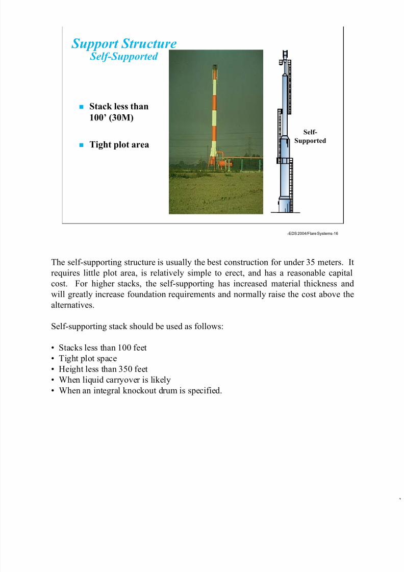
Support Structure Self-Supported
Stack less than
100’ (30M)
Tight plot area
Self-
Supported
The self-supporting structure is usually the best construction for under 35 meters. It
requires little plot area, is relatively simple to erect, and has a reasonable capital
cost. For higher stacks, the self-supporting has increased material thickness and
will greatly increase foundation requirements and normally raise the cost above the
alternatives.
Self-supporting stack should be used as follows:
• Stacks less than 100 feet
• Tight plot space
• Height less than 350 feet
• When liquid carryover is likely
• When an integral knockout drum is specified.

7/17/2019 Flare Systems
http://slidepdf.com/reader/full/flare-systems-568f385db390e 17/93
EDS 2004/Flare Systems-17
Self-Supportive Structures
Description
Self-supported flare
stack is utilized for
structures from 20
to 350 feet tall (6 to
100 meters).
Usually this design
has the lowest
installed cost and
requires the smallest
plot area.
When to Use
• Stacks less than
100 feet (30
meters)
• Tight plot area
• When liquid
carry-over is
likely
• When integral
drum is specified
When Not to Use
• Stacks taller
than 350 feet
(100 meters)
• Cost sensitive
applications
greater than
100 feet (30
meters
The self-supported flare stack is utilized for structures from 20 to 350 feet tall.
Usually this design has the lowest installed cost and requires the smallest land area.
Self-supporting stack should be used as follows:
• Stacks less than 100 feet
• Tight plot space
• Height less than 350 feet
• When liquid carryover is likely
• When an integral knockout drum is specified.
Self-supporting stacks should not be used for:
• Stacks taller than 350 feet• Cost sensitive applications greater than 100 feet

7/17/2019 Flare Systems
http://slidepdf.com/reader/full/flare-systems-568f385db390e 18/93
EDS 2004/Flare Systems-18
Support-Structure Derrick
Derrick
Stacks over 250' (75M)
Tight plot area
Gas temperature over
450 F(232 C)
When plot space is a concern, a derrick structure is normally used. In addition,
when thermal expansion is a problem, derrick structures are also used. Derricks
typically require increased capital investment and foundation requirements
compared to a guyed stack. The derrick structure will typically be double the price
of guyed wire support. They also require more erection time because the derrick
must be built on-site.
Derrick supported flare stacks are used for structures from 150 to 550 feet tall.
They are used in the following application:
• When plot space is tight
• On stacks over 250 feet tall
• When gas temperatures are over 450°F
• When the customer strongly prefers the derrick structure• With offshore systems

7/17/2019 Flare Systems
http://slidepdf.com/reader/full/flare-systems-568f385db390e 19/93
EDS 2004/Flare Systems-19
Derrick Structures
Description
Used for
structures from
150 to 550 feet
tall (45 to 266
meters).
Relatively easy
to erect and has
superior
strength when
assembled.
When Not to Use
• Stacks less than
250 feet (75
meters)
• Cost sensitive
applications
When to Use
• Plot space is
tight
• Stacks over 250
feet (75 meters)
• Gas
temperatures
are over 450
F
(232
C)
• With Offshore
systems
Derrick supported flare stacks are used for structures from 150 to 550 feet tall.
They are used in the following application:
• When plot space is tight
• On stacks over 250 feet tall
• When gas temperatures are over 450°F
• When the customer strongly prefers the derrick structure
• With offshore systems
They should not be used for the following conditions:
• Stacks less than 250 feet tall
• Cost sensitive applications.
They are usually modular in design for ease of erection. One vendor uses 39 foot
sections which can be assembled at grade then lifted for erection. The three leg
design reduces the number of pieces which reduces the erection costs.

7/17/2019 Flare Systems
http://slidepdf.com/reader/full/flare-systems-568f385db390e 20/93
EDS 2004/Flare Systems-20
Support-Structure(Guyed)
Guyed
Stacks over 250'(75M)
Low capital cost
The simplest and generally most economical design is the guyed support. Capital
cost and foundation requirements are minimal. However, the guy wires can cause
some problems. A significant plot area is often required to accommodate the wires.
The radius is generally equal to two-thirds the height for most guyed flares but can
approach 80% of the height for very tall flares (on the order of 150 meters).
Thermal expansion of the stack is another problem to consider. A high design
temperature such as 300°C will require some method to accommodate thermal
expansion. Some vendors can provide this through innovative stack and guy wire
design. However, a more practical solution is to enclose the flare pipe in a structure
that can support the horizontal load yet allow freedom to move vertically.

7/17/2019 Flare Systems
http://slidepdf.com/reader/full/flare-systems-568f385db390e 21/93
EDS 2004/Flare Systems-21
Guyed Structures
Description
Guy wire support
flare stacks are
typically the
lowest material
cost system, but
they require the
largest plot area.
Used in systems
from 100 to 700
feet tall (30 to 213meters).
When to Use
• Stacks over 100
feet (30 meters)
• Radius equal to
stack height
available for guy
wires
• Low capital cost
is required
• Liquid carry over
is unlikely
When Not to Use
• Stacks less than
100 feet (30
meters)
• Tight plot area
• Liquid carry
over likely
Guyed wire supported flare stacks are typically the lowest material cost system, but
they require the largest plot area. Used in systems from 100 to 700 feet tall.
Guyed supports are normally used as follows:
• Stack height greater than 100 feet
• Radius equal to stack height available for guy wires
• Low cost important
• Liquid carryover is unlikely
Guyed supports should not be used in the following application:
• Stacks less than 100 feet
• Tight plot spaces• Liquid carryover is likely

7/17/2019 Flare Systems
http://slidepdf.com/reader/full/flare-systems-568f385db390e 22/93
EDS 2004/Flare Systems-22
Radiation Effects
Solar Radiation on Earth ~ 300 Btu/hr-ft 2
Most of us learned about radiation from the effects of the sun. We found that by
staying in the sun we feel relatively warm and by going into shade we will get
cooler. Some have even learned the hard way about getting a sun burn with is
impart due to the solar radiation of the sun.
A flare stack’s height reduces the intensity of radiant heat at grade level, to protect
personnel and equipment. This intensity is often calculated by assuming that heat
radiates uniformly and spherically from the center of the flame.
Emissivity is defined as the fraction of the available chemical energy (calculated as
the mass flow times the lower heating value of the flared gas) that is radiated as
heat. As the flame, about 0.4 of this energy actually radiates as heat. However, as
this energy radiates spherically, it decays inversely with the square of the distance it
travels, and some of it is absorbed by the atmosphere.
After the heat has radiated 100 meters, the apparent emissivity is more like 0.15,
assuming spherical radiation and neglecting all other factors. The wide range of
measured radiation efficiencies (from 0.05 to 0.35) and diverse statements from
vendors reflect the complex dependence of emissivity.

7/17/2019 Flare Systems
http://slidepdf.com/reader/full/flare-systems-568f385db390e 23/93
EDS 2004/Flare Systems-23
Radiation Theory
L2 (ft2) = (t)*(f)*(R)/(4*PI*K)
Where: t = fraction of heat intensity transmitted
f = fraction of heat radiated
R = net heat release (Btu/hr)
K = allowable radiation (500 Btu/hr-ft2)
PI = 3.14159
L = minimum distance from flare tip
The radiation source is generally though of as being located halfway up the flame.
A common approach to the prediction of the flare flame radiation to a point on or
near garde is simplify the geometric problem by assuming the flame has a single
radiant epicenter and to use a simple factor to cover a number of radiative heat-
transfer variables.
The radiant heat intensity to a unit area aligned for maximum reception can be
expressed in the above formula. Most of the published radiant intensity prediction
methods use the lower heating value (LHV) of the gas in calculating the heat release
rate, Q. In order to determine the line-of-sight distance form the radiant center to
the point of interest, you need to locate the center. This requires an understanding
of flame length and the path of the flame follows as it leaves the flare burner.
API 521 “Guide for Pressure-Relieving and Depressing Systems” presents a methodof calculating fraction of heat radiated. Flame length is determined as a function of
heat release. Flame lean is determined by a momentum relationship between the jet
velocity and the wind velocity. The radiant center is given a somewhat unrealistic
location at the center of a straight line drawn between the end of the flame and the
flare tip. An intensity of 4.73 kW/m2 (1500 Btu/h-ft2) is recommended for areas
where emergency actions lasting several minutes may be required.

7/17/2019 Flare Systems
http://slidepdf.com/reader/full/flare-systems-568f385db390e 24/93
EDS 2004/Flare Systems-24
Heat Release from a Flare
R = Heat Release (Btu/hr)
W = Flare Gas Flow Rate (lb/hr)
B = Net heating value (Btu/lb)
R = W * B
The above formula determines the heat release from a flare. Factors to consider
regarding thermal radiation levels is that clothing provides shielding, allowing only
a small part of the body to be exposed to the full intensity. In the case of radiation
emanating from an elevated flare, standard personnel protection, such as hard hats
can reduce thermal exposure. A level of 5000 Btu/hr-ft2 (15.77 kW/m2) is the heat
intensity on structures and in areas where operators are not likely to be performing
duties and where shelter from radiant heat is available such as behind radiation
shields.
The conservative design approach used mostly ignores wind effects and calculates
the distance assuming the center of radiation is the base of the flame (at the flare
tip), not in the center.
The total emissivity of the flame is the sum of the emmissivities of the gases andsolids present in the flame. Combustion of hydrocarbon gas results in soot and
smoke. If soot is burned completely within the flame, it becomes Carbon dioxide.
If it does not burn completely, it leaves the flame envelope as smoke.
To determine gas emissivity of a flame is difficult. For gases within an enclosure
such as a fired heater, one can make a fairly accurate estimate of the gas
composition, thickness and temperature. For a flare it is more difficult

7/17/2019 Flare Systems
http://slidepdf.com/reader/full/flare-systems-568f385db390e 25/93
EDS 2004/Flare Systems-25
Radiation Theory
Exposure Times Necessaryto Reach the Pain Threshold
Times to Pain Threshold
(Seconds)
60
40
30
16
9
6
4
2
Radiation Intensity
Btu/hr-ft2 Kilowatts per M2
550
740
920
1500
2200
3000
3700
6300
1.74
2.33
2.90
4.73
6.94
9.46
11.67
19.87
Threshold of Pain
Safe Limit440 Btu/(hr) (ft)2
7
6
5
4
3
2
1
010 20 30 40 50 60
Exposure Time, Sec.
What level is acceptable for radiation. An acceptable level under one set of
conditions may not be acceptable under other conditions. Frequently, one radiant
intensity level is allowed for people, whereas another higher level is permitted for
equipment. When discussing the allowable level for people, it is common to tie the
level to some time period of exposure. Different levels are usually specified for
plant personnel and the public.
A heat intensity of 4.73 kW/m2 (1500 Btu/h-ft2) for several seconds (16 seconds).
This 16 seconds allows for situations where a worker is infrequently in the flare area
or must go into the flare area briefly to take some action. This level is also
acceptable when the exposure is more general but the maximum flaring event itself
is of limited duration.
The chart above shows the exposure times necessary to reach the pain threshold.The point where there is a safe zone is at 440 Btu/h-ft2. A related issue is how much
importance should be given to solar radiation in establishing the design radiant heat
intensity levels. To be additive, the worker must be aligned with the flare and the
sun in such a manner that the two exposures are truly additive. The above chart
does not take into account solar radiation.

7/17/2019 Flare Systems
http://slidepdf.com/reader/full/flare-systems-568f385db390e 26/93
EDS 2004/Flare Systems-26
Contours of Radiant Heat Intensity
Protection
Required for
Equipment
Boundary for Radiant Heat Intensity
(3000 Btu Hr/Sq.Ft.)
Protection
Required
for Personnel
Boundary
for Radiant
Heat Intensity
(1500 Btu/Hr/Sq.Ft.)
- Normally Fenced in with
Warning Signal
Safe Boundary
(440 Btu/Hr/Sq.Ft.)
It is important that the emissivity of the flame not be confused with the fraction of
heat radiated. The emissivity of a flame is a function of the combined emissivities
of the gases and solids in the flame at a certain temperature. The fraction of heat
radiated, on the other hand, is an overall characteristic of a flame that accounts for
gas composition, flame type,l state of fuel/air mixing, soot and smoke formation,
quantity being burned, flame temperature and flare burner design. The fraction of
heat radiated is determined empirically and must be used in the same manner that it
was determined.

7/17/2019 Flare Systems
http://slidepdf.com/reader/full/flare-systems-568f385db390e 27/93
EDS 2004/Flare Systems-27
FlareTip
Environmentally
acceptable
combustion
Tips normally
proprietary in
design
Flame Stability
Ignition
Reliability
Exit Velocity 1 to
600ft/s (.3 to 183
m/s)
Exit velocity at
50% of sonic
velocity
Multiple Pilot
Burners
Surrounding
Windshield
The flare tip assembly shall be complete with pilots, pilot flame sensors, noise
muffler, steam manifolds and stem jets. The flare tip shall also include all required
pilot gas manifolds and steam distribution headers, rings, manifolds and runners for
complete smokeless operation. The upper 10 feet of the flare tip shall be 310
stainless steel minimum.
The lower half shall be 304 stainless steel minimum. The flame stabilizers shall be
310 stainless steel. The noise muffler shall be refractory lined carbon steel. If
refractory lined tips are furnished, the detail of the lining and method of attachment
to the flare tip shall be shown.
Flare stack diameter is generally sized on a velocity basis, although pressure drop
should be checked. A maximum velocity of up to 0.5 Mach for peak, short-term,
infrequent flow, with 0.2 Mach maintained for the more normal and possibly morefrequent conditions for low-pressure flares.
Pressure drops of 2 psig (14 kilopascals) have been satisfactorily used at the flare
tip. Too low a tip velocity can cause heat and corrosion damage. The burning of
the gases becomes quite slow, and the flame is greatly influenced by the wind.

7/17/2019 Flare Systems
http://slidepdf.com/reader/full/flare-systems-568f385db390e 28/93
EDS 2004/Flare Systems-28
Flare Tip DesignConsiderations
– Design for maximum
flow rates
– Design for maximum
temperatures
– Design for wind
conditions
– Design for minimum
flow rates
Flare Tip Design
The above flare tip is one that was placed in the UK with very high wind loads.
This specific flare tip only lasted 3 years before it had to be replaced. In general,
flare tips last up to 10 years before they need to be replaced. With respect to life of
the flare tip, a failure mode which have been observed involves cracking of the shell
of the flare burner. This cracking invariably propagates from the end of a fillet weld
on brackets and attachments welded to the shell of the flare tip. During bucking of
the flare tip which results from the uneven temperature differentials of flame
impingement, the stresses concentrate at the stress riser cause by the weld and
propagates a crack through the shell. To avoid this type of problem, plug-welded
brackets on the flare tip are used. This complete circle plug-welded approach
eliminates any stress riser with its potential for cracking.

7/17/2019 Flare Systems
http://slidepdf.com/reader/full/flare-systems-568f385db390e 29/93
EDS 2004/Flare Systems-29
High and Too Low Relief Flow RatesCan Cause Flame Instability
a. Flame Dip b. Flame Blowoff c. Analysis Of Flame Dip
Air Aspiration
Pipe
Methane
V
D
Air
Air
Intrusion
The exit velocity, heat radiation and sonic velocity for flares is critical.
Sonic Velocity = 233(Heat radiated,(Btu/hr-ft2)*Gas temp(R)/MW)^0.5
Exit velocity f/s = (MACH)*(Sonic Velocity)
Flame stability is extremely important in flare tip design. A flameout does not
appear to be a real problem at either low or high venting flowrates. As log flow rate
velocities air intrudes into the top of the stack. If the flow rate is sufficient to
produce a flame visible from the ground, air intrusion usually is not significant. At
low velocities, combustion can take place inside the flare. When the slow upward
flow of a lighter-than-air gas permits air to flow downward along the stack wall, a
flame dip occurs. A diffusion flame propagates into this region and is quenched at
the wall, then air flows downward again, causing another flame dip, and the cycle
repeats it self. If the velocity of the relief gas rises until it exceeds the flamevelocity at every point, the flame will be lifted to another stable position above the
flare tip. This is called blowoff with flame extinguishment is called blowout.
Turbulence promoting flame holders and pilots effectively stabilize flames at high
gas velocities.

7/17/2019 Flare Systems
http://slidepdf.com/reader/full/flare-systems-568f385db390e 30/93
EDS 2004/Flare Systems-30
Flare Efficiency
Efficiency of flare
depends on the following
– Type of fuel
– Flow rate of fuel
– Wind velocity
– Ambient turbulence
– Height of the stack
– Presence of HC
droplets
– Presence of waterdroplets
The use of the term “flare efficiency” can be somewhat misleading because of the
wide variety of definitions that have been used in the past. The most rigorous and
universal definition of efficiency is the “Combustion Efficiency” which for a
hydrocarbon flare, is simply the mass of carbon in the form of carbon dioxide which
is produced by the flare divided by the mass of carbon in the form of fuel entering
the flare.
The “Hydrocarbon Destruction Efficiency” can also be useful in characterizing flare
performance. It is defined in a somewhat different manner as amount of
hydrocarbons entering the flare in the flare gas minus the amount of unburned
hydrocarbons leaving the flare all divided by the amount of hydrocarbons entering
the flare.
This is the fraction of hydrocarbons destroyed by the flare. It should be noted thatthis definition does not consider the form of the chemicals into which the
hydrocarbons are converted via combustion.
7/17/2019 Flare Systems
http://slidepdf.com/reader/full/flare-systems-568f385db390e 31/93
EDS 2004/Flare Systems-31
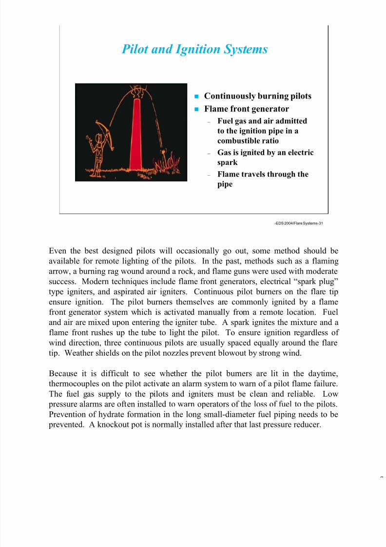
Pilot and Ignition Systems
Continuously burning pilots Flame front generator
– Fuel gas and air admitted
to the ignition pipe in a
combustible ratio
– Gas is ignited by an electric
spark
– Flame travels through the
pipe
Even the best designed pilots will occasionally go out, some method should be
available for remote lighting of the pilots. In the past, methods such as a flaming
arrow, a burning rag wound around a rock, and flame guns were used with moderate
success. Modern techniques include flame front generators, electrical “spark plug”
type igniters, and aspirated air igniters. Continuous pilot burners on the flare tip
ensure ignition. The pilot burners themselves are commonly ignited by a flame
front generator system which is activated manually from a remote location. Fuel
and air are mixed upon entering the igniter tube. A spark ignites the mixture and a
flame front rushes up the tube to light the pilot. To ensure ignition regardless of
wind direction, three continuous pilots are usually spaced equally around the flare
tip. Weather shields on the pilot nozzles prevent blowout by strong wind.
Because it is difficult to see whether the pilot burners are lit in the daytime,
thermocouples on the pilot activate an alarm system to warn of a pilot flame failure.The fuel gas supply to the pilots and igniters must be clean and reliable. Low
pressure alarms are often installed to warn operators of the loss of fuel to the pilots.
Prevention of hydrate formation in the long small-diameter fuel piping needs to be
prevented. A knockout pot is normally installed after that last pressure reducer.
7/17/2019 Flare Systems
http://slidepdf.com/reader/full/flare-systems-568f385db390e 32/93
EDS 2004/Flare Systems-32
Pilot Burners
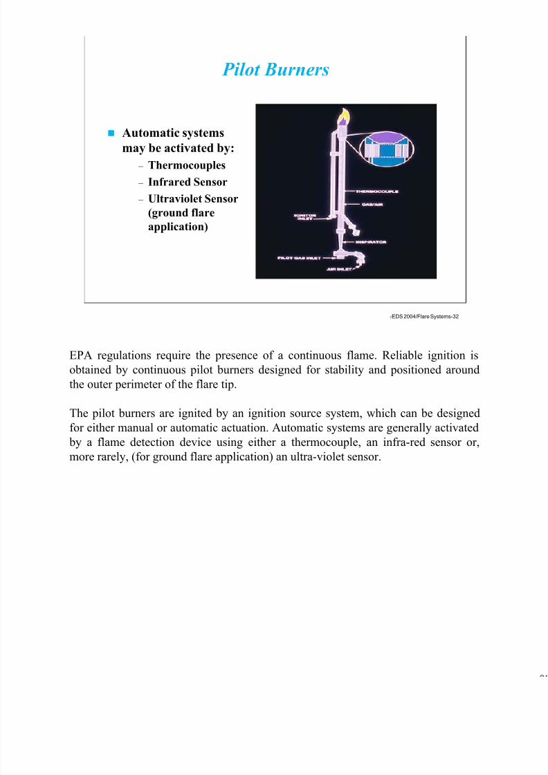
Automatic systemsmay be activated by:
– Thermocouples
– Infrared Sensor
– Ultraviolet Sensor
(ground flare
application)
EPA regulations require the presence of a continuous flame. Reliable ignition is
obtained by continuous pilot burners designed for stability and positioned around
the outer perimeter of the flare tip.
The pilot burners are ignited by an ignition source system, which can be designed
for either manual or automatic actuation. Automatic systems are generally activated
by a flame detection device using either a thermocouple, an infra-red sensor or,
more rarely, (for ground flare application) an ultra-violet sensor.

7/17/2019 Flare Systems
http://slidepdf.com/reader/full/flare-systems-568f385db390e 33/93
EDS 2004/Flare Systems-33
Installation of Thermocouples
Correct Installation Incorrect Installation
The above picture shows a correct and incorrect installation of a thermocouple. The
correct installation has the thermocouple at the interior of the pilot where as the
incorrect installation is on the outside. By placing the thermocouple on the outside,
there is a chance of an incorrect reading.
The pilot flame shall always be present at the burner tip. Each pilot shall have a
thermocouple attached to determine the flame temperature. Pilot flame failure can
be sensed by local or remote monitoring. Thermocouple failure can cause a
problem if the flare is unavailable for maintenance over long periods of time.
Sometimes two thermocouples are mounted on each pilot with separate leads
running down the stack. This allows for switching of the active thermocouple by
simply swapping the leads.

7/17/2019 Flare Systems
http://slidepdf.com/reader/full/flare-systems-568f385db390e 34/93
EDS 2004/Flare Systems-34
Pilot Windshield
Allows pilot tooperate at wind
speeds greater
than 100 mph
Should always be
specified
Prevents
misreading of the
thermocouples
Pilots shall be able to withstand the effects of rain, snow, and wind speeds greater
than 100 miles per hour. They must also stand up to the high temperature caused by
flaring.
Pilot windshield design, although often overlooked, is extremely important.
Without an effective design the risk of an inoperable flare is a real danger. Even if
the flame is not extinguished by high winds, it may be directed away from the flare
and rendered useless.
To prevent this hazardous condition from arising, the number of pilots used on a
flare should be increased as the size of the flare is increased. Large flares require
the use of several pilots to assure ignition in any wind direction. The size and
number of pilots is determined by the size, design, and function of the flare, and the
heat level of the waste gas.

7/17/2019 Flare Systems
http://slidepdf.com/reader/full/flare-systems-568f385db390e 35/93
EDS 2004/Flare Systems-35
Flame Front Generator Ignition System
E
DAir
Gas To Pilot #3
Gas To Pilots
B A
C
H
J
F
To Pilot #2
To Pilot #1
The above drawing show a flame front generator ignition system. They work by
introducing a flammable mixture of air and gas into a 1 inch pipe leading up to the
pilot. Once this mixture is distributed throughout the length of the pipe, it is ignited
by an electric spark plug. A flame front will then travel through the pipe up to the
flare tip, lighting the pilot. Many flame front generators are designed to light a flare
as far as one mile away.
The following is a typical operating instruction for using flame front generator
ignition system:
• Open the air valve and set air pressure at 10 psig
• Open the gas valve and the gas pressure at 10 psig.
• Purge lines for two to three minutes, depending on distance from flame front
generator to flare pilot tip.• Spark to light the mixture.
• If nothing happens, purge and spark again.
• If nothing happens, reduce the air pressure, and repeat purging and sparking.
• If still nothing happens, lower the air pressure further in several steps and
purge and spark again.
• If still nothing happens, try higher air pressures.
Pressure settings depend on the gravity of the fuel gas.

7/17/2019 Flare Systems
http://slidepdf.com/reader/full/flare-systems-568f385db390e 36/93
EDS 2004/Flare Systems-36
Flare Control Panel
Flare ControlPanel includes
the following:
– Pilot Gas
– Steam Control
– Pilot Ignition
System
The above photograph shows a flare control panel which contains the pilot gas
control the steam control and the pilot ignition system for the flare system.
Flare system control can be completely automated or completely manual.
Components of a flare system which can be controlled automatically include the
auxiliary gas, steam injection, and the ignitions system. Fuel gas consumption can
be minimized by continuously measuring the vent gas flow rate and heat content
(Btu/scf) and automatically adjusting the amount of auxiliary fuel to maintain the
required 300 Btu/scf for steam-assisted flares.
Steam consumption can likewise be minimized by controlling flow based on vent
gas flow rate. Steam flow can also be controlled using visual smoke monitors.
Automatic ignition panels sense the presence of a flame with either visual or
thermal sensors and reignite the pilots when flameout occurs.

7/17/2019 Flare Systems
http://slidepdf.com/reader/full/flare-systems-568f385db390e 37/93
EDS 2004/Flare Systems-37
Pilot Gas Requirement
Flare Tip Diameter (IN) Number of Pilot Burners (N)
1-10
12-24
30-60
>60
1
2
3
4
The average pilot gas consumption based on
an energy-efficient model is 70 scf/hr. The
annual pilot gas consumption (Fp) is
calculated by:
Fp (Mscf/yr) = (70 scf/hr)*(N)*(8,760
hr/yr)
Fp (Mscf/yr) = 613*N
N can be calculated from the following table:
Pilot gas is critical for flare application. The average pilot gas consumption based
on new energy efficient model is approximately 70 scf/hr. Therefore, as shown in
the above table, the annual pilot gas consumption in Mscf/yr is based on 613 times
the number of pilot burners.
The table shows that under a ten inch flare tip only one pilot burner is required.
From 12 to 24 inches, two pilot burners are required. Over 24 inches to 60 inches,
three pilot burners are required. Over 60 inches, at least four pilot burners are
required.

7/17/2019 Flare Systems
http://slidepdf.com/reader/full/flare-systems-568f385db390e 38/93
EDS 2004/Flare Systems-38
Multiple Pilots
Multiple pilots allow
one pilot to fail
Most flares have two
to four pilots
Equally spaced
around the flare
The above drawing shows a three pilot arrangement. This allows one pilot to fail
and have the other two in operation. The pilots in this case would be equally spaced
around the flare. Therefore, they would be space at 360 degrees divided by 3 or at
120 degrees from one another.
EPA regulations require the presence of a continuous flame. Reliable ignition is
obtained by continuous pilot burners designed for stability and positioned around
the outer perimeter of the flare tip. The pilot burners are ignited by an ignition
source system, which can be designed for either manual or automatic actuation.
Automatic systems are generally activated by a flame detection device using either
a thermocouple, an infra-red sensor or, more rarely, (for ground flare application) an
ultra-violet sensor.

7/17/2019 Flare Systems
http://slidepdf.com/reader/full/flare-systems-568f385db390e 39/93
EDS 2004/Flare Systems-39
Safety Aspect
Two of the three elements for explosion are
always present in a flare system
Fuel
Oxygen Ignition
Stacks shall be purged with fuel gas to ensure safe flare operation against explosion
and detonation. A question asked is how much purge gas is required? The answer
is important because of the cost to purge a flare which may run a refinery $50,000
per year.
Combustion can be defined as the rapid chemical combination of oxygen with the
combustible elements of fuel. There are just three combustible chemical elements
of significance - carbon, hydrogen, and sulfur. Sulfur is usually of minor
significance as a source of heat but it can be major significance in corrosion and
pollution problems.
The objective of good combustion is to release all of this heat while minimizing
losses from combustion imperfections and superfluous air. The combination of the
combustible elements and compounds of a fuel with all the oxygen requirestemperature high enough to ignite the constitutes, mixing or turbulence, and
sufficient time for complete combustions.

7/17/2019 Flare Systems
http://slidepdf.com/reader/full/flare-systems-568f385db390e 40/93
EDS 2004/Flare Systems-40
Purging
Flare purge gas
– Any gas which cannot go to
dew point under any
condition of operation
• Fuel Gas
• Inert Gas
• Nitrogen
– Purge Rate
• Flare Stack
— Linear velocity 1FPS to
5FPS (.3 to 1.5 m/s)
• Flare stack with molecular
seal
— 0.10 FPS to 0.20 FPS (.03
to 0.06 m/s)
Air or oxygen in a flare system is extremely dangerous. For this reason, flare
systems should be purged. Dry seals are used to reduce the rate of purge gases
required to keep air out of the system. The total volumetric flow to the flame must
be carefully controlled to prevent low flow flashback problems and to avoid flame
instability. Purge gas, typically natural gas, N2 or CO2, is used to maintain a
minimum required positive flow through the system. If there is a possibility of air
in the flare manifold, N2 or another inert gas must be used to prevent the formation
of an explosive mixture in the flare system. To ensure a positive flow through all
flare components, purge gas injection should be at the farthest upstream point in the
flare transport piping.
The minimum continuous purge gas required is determined by the design of the
stack seals, which are usually proprietary devices. Modern labyrinth and internal
gas seals are stated to require a gas velocity of 0.001 to 0.04 ft/s (at standardconditions). Using the conservative value of 0.04 ft/s and knowing the flare
diameter (in), the annual purge gas volume, F pu, can be calculated:
F pu (Mscf/yr)
= (0.04 ft/s)(πD^2/4/144 ft2)(3,600 sec/hr)(8.760 hr/yr)= 6.88D^2 (Mscf/yr)

7/17/2019 Flare Systems
http://slidepdf.com/reader/full/flare-systems-568f385db390e 41/93
EDS 2004/Flare Systems-41
Purge Gas Requirements
Prevents flashback problems Flare operates at positive pressure
Purge all subheaders (upstream)
.04 feet per second to 1 feet per second
(.01 meters per second to 0.33 meters per second)
F (Mscf/yr) = (0.04 ft/sec)*((PI*D^2/4)/144 ft2))*(3600 sec/hr)*(8,760 hr/yr)
F (Mscf/yr) = 6.88*D^2
There is another minimum flare tip velocity for operation without flashback or
instability. This minimum velocity is dependent on both gas composition and
diameter and can range from insignificant amounts on small flares to 0.5 ft/s on
greater than 60-inch diameter units.
Purge gas is also required to clear the system of air before startup, and to prevent a
vacuum from pulling air back into the system after a hot gas discharge is flared.
(The cooling of gases within the flare system can create a vacuum.) The purge gas
consumption from these uses is assumed to be minor.

7/17/2019 Flare Systems
http://slidepdf.com/reader/full/flare-systems-568f385db390e 42/93
EDS 2004/Flare Systems-42
Dry Seals
Molecular Seals
Double Seals
Fluidic Seals
Airrestors
Air in the flare stack is a serious problem. There are two common types of flare dry
seals:
• Diffusion type - (Molecular Seal, Double Seal)
• Velocity Seal - (Fluidic Seal, Airrestor)
These are located just below the flare tip and are used to reduce the amount of purge
gas required to prevent air from getting back into the stack. The molecular seal and
double seal uses the difference in molecular weights of the purge gas and the air to
form a gravity seal which prevents the air from entering into the stack. An inverted
bucket forces the incoming air through two 180 degree bends before it enters the
flare tip. If the purge gas is lighter than air, the purge gas will accumulate in the top
of the seal and prevent the air from infiltrating the system.
The velocity seal, which includes the fluidic seal and the airrestor, works under the
premise that infiltrating air enters through the flare tip and hugs the inner wall of the
flare tip.

7/17/2019 Flare Systems
http://slidepdf.com/reader/full/flare-systems-568f385db390e 43/93
EDS 2004/Flare Systems-43
Liquid
Drain
Molecular Seal
Flare
Assembly
Prevents explosions
Prevents entry of air
Reduces purge gas
Performs silently with
small pressure drop
Molecular Seal
The molecular seal has a baffled cylinder arrangement which forces the incoming
air through two 180 degree bends one bend up and one bend down before it can
enter into the flare stack. If the purge gas is lighter than air, the purge gas will
accumulate in the top of the seal and prevent the air from getting into the system. If
the purge gas is heavier than air, the purge gas will accumulate in the bottom of the
seal and prevent air from getting into the system.
The molecular seal reduces the purge gas velocity required through the tip to 0.04
feet per second. Some purge gas composition the rate will limit oxygen levels to
below 0.1%. These low purge rates do not prevent burnback inside the flare tip,
which will result in short tip life. This effect will deteriorate the metal wall of the
flare tip of the molecular seal and is hidden until the flame burns through the tip or
seal. This will result in the tip or seal to be replaced and cause shutdown for
immediate maintenance.
Molecular seals are purged at 0.4 feet per second to keep the flame out of the flare
tip and insure proper flare life.

7/17/2019 Flare Systems
http://slidepdf.com/reader/full/flare-systems-568f385db390e 44/93
EDS 2004/Flare Systems-44
Outlet To Flare Burner
Clean-Out
Double Seal
When air enters a stack, convection (not diffusion, which is much too slow) is
almost certainly the controlling process. How much purge will prevent the entry of
air depends on the type of dry seal installed.
The above picture is that of a double seal. The double seal is similar in design
principle as that of the molecular seal. Both designs work on the basis of density
differences.
The flare gases are required to go up the double seal and then make a 180 degree
reversal then go down a distance and then make another 180 degree reversal before
being sent to the flare tip.
These 180 degrees reversals prevents the air from getting back into the flare
headers. If air does get into the double seal, most of the air will be stuck at the pointnear the clean-out zone.

7/17/2019 Flare Systems
http://slidepdf.com/reader/full/flare-systems-568f385db390e 45/93
EDS 2004/Flare Systems-45
Flare
TipAir Air
Flow PathOf Flare
Gas
Fluidic Seal
The velocity seal or fluidic seal works under the premise that incoming air enters
through the flare tip and hugs the inner wall of the flare tip. The velocity seal is a
cone shaped obstruction with single or multiple baffles as shown in the above
picture.
These baffles force the air away from the wall where it encounters the focused
purge gas flow rate and is swept out of the tip. This seal reduces the purge gas
velocity through the tip to 0.04 feet per second. This rate keeps oxygen
concentrations below 4 to 8% oxygen. Without the velocity seal, the velocity in the
stack would have to be increased.

7/17/2019 Flare Systems
http://slidepdf.com/reader/full/flare-systems-568f385db390e 46/93
EDS 2004/Flare Systems-46
Smoking
Smokeless Operation
Smokeless Flare Operation
Smoke is generated from fuel that has a carbon to hydrogen ratio greater than 35%
by weight. The principle of the steam-assist flare is to reduce the formation of
smoke by reducing the carbon to hydrogen ration. This can be achieved by using a
cented steam feed and steam nozzles at the flare tip. The center feed is used to
provide a wide range of flaring rates while the steam nozzles agitate the gas
turbulently to achieve a good mix with air. The minimum allowable heating value
for all types of assist flare is 300 Btu/scf. The majority of today’s flares are steam-
assist, because of their significant advantages. First, they have been proved to be
successful in many years of operation. Next, when plants undergoes expansion, the
system can be expanded as well without having difficulty to maintain smokeless
emissions. Steam-assisted flare are extremely useful in variable flow rates of
flaring. Some disadvantages are that there is a cost of steam supply as well as the
capital cost involved.
Air assisted flares employs the same principles as the steam assisted flare but is
normally more costly. The design of the air assist flare is complicated because the
design features as stack inside a stack. Waste gas goes inside the outer stack, while
air is force through the inner stack. The amount of operational purge gas required
for air assist flares is typically 50% higher than the steam assisted flare.

7/17/2019 Flare Systems
http://slidepdf.com/reader/full/flare-systems-568f385db390e 47/93
EDS 2004/Flare Systems-47
In general, the following equation can be used:
Wsteam (lb/hr) = Whc (lb/hr) * [0.68-(10.8/MW)]
Smoke Suppression Methods
– Steam injection
– High pressure gas injection
– Low pressure air
– Internal energized flare
Steam Requirements and Smoke Suppression Methods
Smoke free operation of flares can be achieved by various methods, including steam
injection, injection of high-pressure waste gas, forced draft air or distribution of the
flow through many small burners. The most common type involves steam injection.
The amount of steam required for smokeless burning will depend on the maximum
vapor flow at which smokeless burning is to be achieved and the composition of the
mixtures. The composition involves both the percentage of unsaturated and the
molecular weight.
The higher the molecular weight of a hydrocarbon, the lower the ratio of steam to
carbon dioxide and the greater the tendency to smoke. The amount of steam that
must be injected to maintain a constant steam to carbon dioxide ratio as molecular
weight increases can be calculated in the above formula.
The steam can be injected through a single pipe nozzle located in the center of theflare or through a series of steam/air injectors in the flare through a minifold located
around the periphery of the flare tip or in any combination of those. The steam
injected into the flame zone to create turbulence and aspirate air into the flame zone
by the steam jets. This improved air distribution combined with the steam gas shift
interaction reactors more readily with the flare gases to eliminate fuel rich
conditions which results in smoke formation.

7/17/2019 Flare Systems
http://slidepdf.com/reader/full/flare-systems-568f385db390e 48/93
EDS 2004/Flare Systems-48
50
40
30
20
10
0.4 0.3 0.2 0.1
H/C Ratio by Weight
P e r c e n t o f C a r b o n E s c a p i n g a s B l a c k S
m o k e
Tendency to Produce Black Smoke
As can be seen from the above chart, the lower the Hydrogen to Carbon (H/C)
ration is, the higher the percent of carbon escaping as black smoke. For example, a
H/C ratio of 0.2 results in 19% of carbon escaping as black smoke. Water or steam
reduces smoke formation by the way the steam separates the hydrocarbon
molecules, thereby minimizing polymerization and forms oxygen compounds that
burn at reduced rates and temperatures that are not conductive to polymerization
and cracking. Other theories project that the water vapor reacts with the carbon
particles to form carbon monoxide and carbon dioxide and hydrogen thereby
removing the carbon before it cools and forms smoke.

7/17/2019 Flare Systems
http://slidepdf.com/reader/full/flare-systems-568f385db390e 49/93
EDS 2004/Flare Systems-49
Controller Control Scheme
Flux DensitySignal
Monitor
Field Of View
Steam Nozzles
Steam ControlValve
Automatic Steam Control
Automatic control is the optimum way to minimize steam consumption, supplying
only the required amount to keep the flame smokeless at a particular waste gas
flowrate and also at atmospheric conditions. Excessive steam can produce burning
back into the flare tip, besides increasing flare noise and wasting steam. Steam
injected into the combustion zone also cools the combustion temperature and at a
high excess condition can reduce combustion efficiency.
The picture above shows that steam is controlled by flame appearance. An optical
unit is calibrated to a particular frequency in the infrared spectrum, ensuring
smokeless flaring over the range of flowrates. The system provides a continuous
output signal for control for the steam valve. The sending head detects the changes
of hot carbon flux density and generates a signal, modulating the automatic steam
control valve flowrate only allowing the right amount of steam to make it
smokeless. With this fast response system, the detector is remote and not in contactwith the flare gases. The control is independent of the gas flow rate. In addition,
the system is very convenient since the components are located at grade.

7/17/2019 Flare Systems
http://slidepdf.com/reader/full/flare-systems-568f385db390e 50/93
EDS 2004/Flare Systems-50
Automatic Steam Control
Minimizes steam
consumption
Controlled by the flame
appearance
Calibrated to a
particular frequency in
the infrared spectrum
Manual control of steam involves remote operation of a steam valve by operating
personnel assigned to a unit from which the flare is readily visible. This method is
satisfactory if short-term smoking can be tolerated when a sudden increase in flaring
occurs. With a manual arrangement, close supervision is required. Another method
of controlling steam is using television monitoring with manual control. A feed
forward control system pressure, mass flow or velocity can be used to control steam.
By measuring the amount of flare gas flowing to the flare, the steam rate can be
automatically adjusted to compensate for rate changes. This system would not be
acceptable if there was a lot of changing in the molecular weight say from going
from butane to paraxylene. The feedback system using an infrared sensor as the one
shown above. Infrared sensors are used to detect smoke formation in the flames and
automatically adjust the steam control valve to compensate. One disadvantage of
the feedback system is that the infrared waves are absorbed by moisture, and the
resultant feedback signal is reduced in raining or foggy conditions.

7/17/2019 Flare Systems
http://slidepdf.com/reader/full/flare-systems-568f385db390e 51/93
EDS 2004/Flare Systems-51
Wind
Less Than 50 psig Steam
Steam provide is usually MP steam (150 psig), special designs are available for
utilizing slightly lower pressure steam. The major impact of lower steam pressure
is a reduction in steam efficiency during smokeless turndown conditions. In very
cold climites condensation may enter the flare header and collect and may freeze
therefore, drainage of any condensate which may collect is critical.
Many refineries because they have a lot of LP steam (50 psig) they believe that by
switching from MP to LP will be better. This is not the case and can cause a lot of
problems. By using LP steam, any wind that is at the flare tip will cause the steam
not to be injected in the correct location. Therefore, much more steam will be
required to make the flare smokeless. In addition, depending on the way the wind is
blowing, the steam may not even reach the flare tip. Always try to use MP steam
for smokeless operation for flare tips.
If the steam is introduced at pressures below 10 psig, the desired turbulence or air
entrainment will not be achieved due to insufficient momentum. The use of too
much steam can also cool the flame too much and extinguish it. The flame may, in
these event be reignited by hot zones and extinguishment by the steam again, at
millisecond intervals.

7/17/2019 Flare Systems
http://slidepdf.com/reader/full/flare-systems-568f385db390e 52/93
EDS 2004/Flare Systems-52
Flame Arrestors
Liquid Seals
Flashback Protection
Flame arrestors are passive devises with no moving parts. Liquid seals are active
devices with water as the protection. The flame arrestor prevents the propagation of
flame from the exposed side of the unit to the protected side by the use of wound
crimped metal ribbon type flame cell element. This construction produces a matrix
of uniform openings that are carefully constructed to quench the flame by absorbing
the heat of the flame. This provides an extinguishing barrier to the ignited vapor
mixture.
Under normal operating conditions, the flame arrestor permits a relatively free flow
of gas or vapor through the piping system. If the mixture is ignited and the flame
begins to travel back through the piping, the arrestor will prohibit the flame from
moving back to the gas source.
Flare arrestors have specifically designed heat transfer characteristics for slowmoving flames and low to medium pressure fronts. But flames moving at higher
velocities and carrying higher pressure fronts can pass through a standard inline
flame arrestor.

7/17/2019 Flare Systems
http://slidepdf.com/reader/full/flare-systems-568f385db390e 53/93
EDS 2004/Flare Systems-53
Flare vapor pipingsubmerged
approximately 4 to
12 inches below
the water level
Effective means to
stop a flame front
Liquid Seals
The most effective seal is the liquid seal. A liquid seal is simply a head of liquid
(usually water) within the gas collection header that physically prevents air from
intruding into the system. The liquid head prevents air from going into the system
by preventing a vacuum. The liquid seal does require maintenance and utility
requirements. Make-up water must be available at all times. In addition, freezing
must also be considered. Normally, an overflow is provided to minimize the effects
of hydrocarbon which settles out of the vapor.
Depending on the effluent, a surge drum and pump may be necessary at the flare
base to dispose of the seal liquid properly. The seal drum should be located between
the stack and the other header drums and as close to the flare stack as possible. A
variation of a seal drum is sometime incorporated into the base of the flare stack as
shown in the above diagram.
Continuous removal or intermittent skimming of hydrocarbons that may accumulate
should be considered. If the hydrocarbons are not removed, there is a potential that
the inlet piping may get plugged because of the hydrocarbons.

7/17/2019 Flare Systems
http://slidepdf.com/reader/full/flare-systems-568f385db390e 54/93
EDS 2004/Flare Systems-54
Liquid Seal
Submerged Weir
Welded On End
Of Flare Line
Water Level
To Flare
Water
SupplyFI
Flare Header
Try Cocks For Checking Hydrocarbons
Vent
To Sewer
6" (15 cm)
Baffle
Drain
4" (10 cm) 1 0 F t . ( 3 M ) M i n i m u m
S e w e
r S e a l S h o u l d B e
D e s i g n
e d f o r a M i n i m u m
o f 1
7 5 % o f D r u m ’ s
M a x i m u m O p e r a t i n g
P r e s s u r e
The above liquid seal is of the horizontal type. A minimum of 10 feet is required
from the water level to the centerline of the outlet of the flare header. The problem
of surging in seal drums can be minimized by the use of a submerged weir with V-
notches on the end of this pipe. The V-notch provides an increased flow area to the
increasing gas flow. This V-notch type principle is similar to that of the bubble cap
trays. Some design details of the liquid seal include anti-swirl or anti-vortex
baffles on the liquid outlet lines. In addition, internally extended liquid outlet
nozzles should be used because sediment will settle out in the drums and not in the
low spot in the lines. This is shown in the above diagram with a 6 inch space
between the top of the sewer outlet and the bottom of the drum.
Designing the vessel nozzles, attachments, supports, and internals one should
consider shock loading that result from thermal effects, slugs of liquid or gas
expansion. Try-cocks as shown in the above diagram are useful in liquid leveldetection instead of level gauges. Instruments should be the simplest and most
rugged available and should be easily maintained (externally mounted and valve).
The use of seals instead of valves and of valves instead of traps is preferred,
primarily because of the nature of the materials handled and the conditions under
which these components must operate.

7/17/2019 Flare Systems
http://slidepdf.com/reader/full/flare-systems-568f385db390e 55/93
EDS 2004/Flare Systems-55
Stop flame propagationwithin a piping system
by means of breaking
the flame into very
small flames via a
crimped wound metal
grid thus quenching
the flame by means of
heat transfer and
dissipation
Flame Arrestor
Extended lengths of pipe allow the flame to advance into more severe states of
flame propagation such as high pressure deflagrations and detonations. Bends in
piping, pipe expansions and contractions, valves or flow obstruction devices of any
kind, cause turbulent flow.
Turbulent flow enhances the mixing of the combustible gases greatly increasing the
combustion intensity. This can result in increased flame speeds, higher flame
temperatures, and higher flame front pressure than would occur in laminar flow
conditions. High pressure deflagrations and detonations can occur more easily at
higher system operating pressures than at near atmospheric levels.
Elevated pressures condense the ignitable gas giving the flame more matter and
energy to release thereby boosting flame heat intensity,A critical concern in flame
arrestor installation is the possibility of a flame stabilizing on the face of the flamecell element. A flame that continuously burns against the flame arrestor element for
a period of time can heat the element above the autoignition temperature resulting
in flame propagation through the element. The time period varies with the type of
element, mixture of air and gas, type of gas and velocity at which the gas stream is
moving.

7/17/2019 Flare Systems
http://slidepdf.com/reader/full/flare-systems-568f385db390e 56/93
EDS 2004/Flare Systems-56
Product Name Liquid Seal Flame Arrestor Function Liquid seal is designed to
stop flame propagationThe arrestor is designed tostop flame propagation
Product Type Active Device Passive Device
Testing Protocol Not available FM USCG API
Maintenance Switches andcleaning
Cleaning of flamecell elements
Failure Modes Switch
malfunctions, liquidfreezing
Corrosion
Liquid Seal Versus Flame Arrestor
The above chart shows the advantages of a liquid seal and the advantages of a flame
arrestor. Liquid seals are much more common in flare system then are the flame
arrestors. Liquid seals are also designed for detonation thereby the location of the
installation is not as critical as that of the flame arrestor.
In the initial state of flame propagation, the gas is ignited and the flame has
propagated a short distance in the piping system. Flame front velocity is below the
speed of sound thus defined as deflagration, and pressure piling is very low which
makes it a low pressure deflagration. The intermediate state the flame has been
allowed to propagate further down the piping system thus increasing both the flame
velocity and pressure piling. The flame front velocity is just below the speed of
sound and the pressure piling effects have increased tremendously resulting in a
high pressure deflagration. The transformation form deflagration to detonation
transition occurs when the flame front pressure and velocity reach an undefinedlimit. This explosive transformation causes the flame to accelerate to sonic,
supersonic or hypersonic.
In the advanced flame state, the flame has been allowed to propagate further down
the piping system allowing detonation to occur. The flame front is moving at
supersonic velocity.
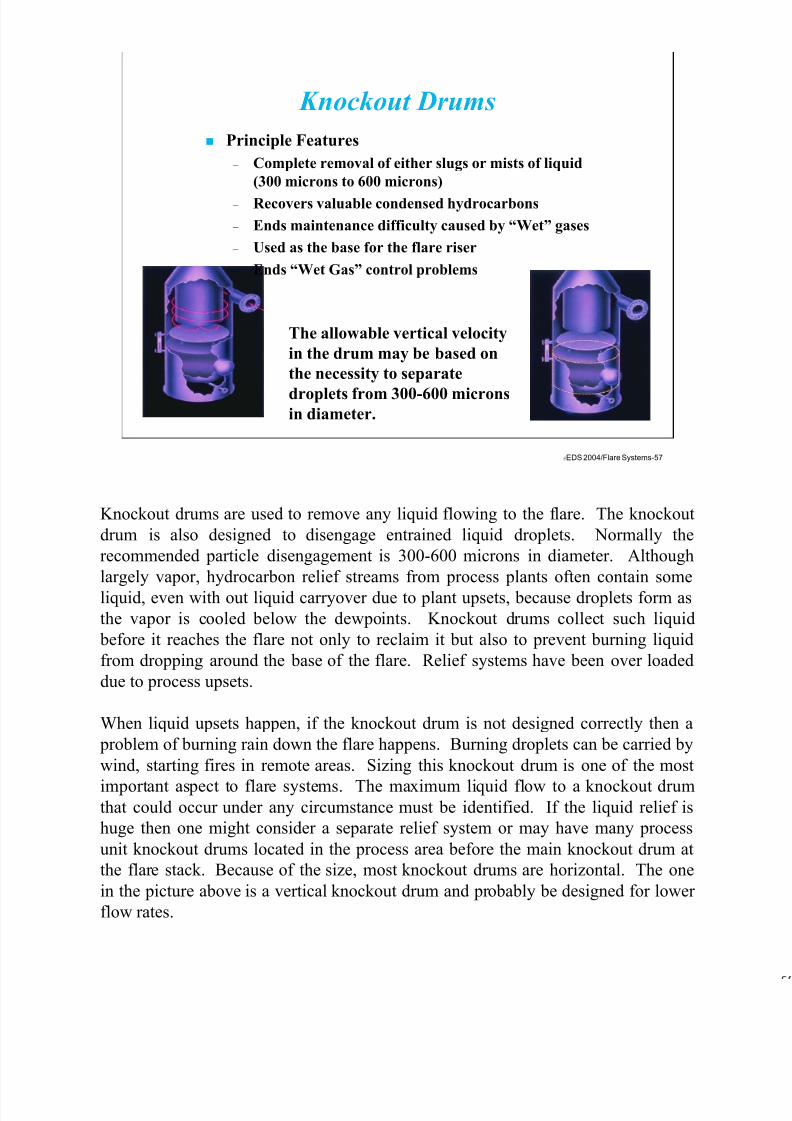
7/17/2019 Flare Systems
http://slidepdf.com/reader/full/flare-systems-568f385db390e 57/93
EDS 2004/Flare Systems-57
Principle Features
– Complete removal of either slugs or mists of liquid
(300 microns to 600 microns)
– Recovers valuable condensed hydrocarbons
– Ends maintenance difficulty caused by “Wet” gases
– Used as the base for the flare riser
– Ends “Wet Gas” control problems
The allowable vertical velocity
in the drum may be based on
the necessity to separate
droplets from 300-600 micronsin diameter.
Knockout Drums
Knockout drums are used to remove any liquid flowing to the flare. The knockout
drum is also designed to disengage entrained liquid droplets. Normally the
recommended particle disengagement is 300-600 microns in diameter. Although
largely vapor, hydrocarbon relief streams from process plants often contain some
liquid, even with out liquid carryover due to plant upsets, because droplets form as
the vapor is cooled below the dewpoints. Knockout drums collect such liquid
before it reaches the flare not only to reclaim it but also to prevent burning liquid
from dropping around the base of the flare. Relief systems have been over loaded
due to process upsets.
When liquid upsets happen, if the knockout drum is not designed correctly then a
problem of burning rain down the flare happens. Burning droplets can be carried by
wind, starting fires in remote areas. Sizing this knockout drum is one of the most
important aspect to flare systems. The maximum liquid flow to a knockout drumthat could occur under any circumstance must be identified. If the liquid relief is
huge then one might consider a separate relief system or may have many process
unit knockout drums located in the process area before the main knockout drum at
the flare stack. Because of the size, most knockout drums are horizontal. The one
in the picture above is a vertical knockout drum and probably be designed for lower
flow rates.
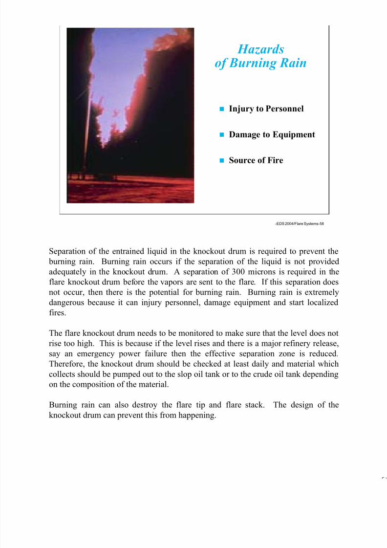
7/17/2019 Flare Systems
http://slidepdf.com/reader/full/flare-systems-568f385db390e 58/93
EDS 2004/Flare Systems-58
Hazardsof Burning Rain
Injury to Personnel
Damage to Equipment
Source of Fire
Separation of the entrained liquid in the knockout drum is required to prevent the
burning rain. Burning rain occurs if the separation of the liquid is not provided
adequately in the knockout drum. A separation of 300 microns is required in the
flare knockout drum before the vapors are sent to the flare. If this separation does
not occur, then there is the potential for burning rain. Burning rain is extremely
dangerous because it can injury personnel, damage equipment and start localized
fires.
The flare knockout drum needs to be monitored to make sure that the level does not
rise too high. This is because if the level rises and there is a major refinery release,
say an emergency power failure then the effective separation zone is reduced.
Therefore, the knockout drum should be checked at least daily and material which
collects should be pumped out to the slop oil tank or to the crude oil tank depending
on the composition of the material.
Burning rain can also destroy the flare tip and flare stack. The design of the
knockout drum can prevent this from happening.

7/17/2019 Flare Systems
http://slidepdf.com/reader/full/flare-systems-568f385db390e 59/93
EDS 2004/Flare Systems-59
Design Considerations Separation of Gas & Liquid
Hydrocarbon relief streams are mainly vapors, but they may carry some liquids that
condense in the collection line. Therefore, material entering the knockout drum will
be a mixture of vapor and liquid. A particle that is 300 microns or less can be
burned in a flare with out hazard. Larger particles shall be removed in the knockout
drum. The liquid is pumped out from the bottom of the knockout drum either for
reuse or for disposal in a slop oil tank.
Knockout drums are either horizontal or vertical. They are available in a variety of
configurations and arrangements that include horizontal drum with the vapor
entering at one end of the vessel and exiting at the top of the opposite end with no
internals. The drum can also be a horizontal drum with the vapor entering at each
end on the horizontal axis and a center outlet. The drum can also be a horizontal
drum with the vapor entering in the center and exiting at the two ends on the
horizontal axis. The drum can also be vertical as the one shown above with thevapor entering with a tangential nozzle. The drum can also be vertical with the
vapor entering at the top of a certain diameter and provided with a baffle so the flow
is directed downward.

7/17/2019 Flare Systems
http://slidepdf.com/reader/full/flare-systems-568f385db390e 60/93
EDS 2004/Flare Systems-60
Design Considerations Liquid Holding Capacity
Selection of the knockout drum arrangements depends on economics. When large
liquid volume storage is required and the vapor flow is high, normally a horizontal
drum is more economical. A split entry or exit reduces the size of the drum for
large flows. As a rule of thumb, when the drum diameter exceeds 12 feet the split
flow arrangements is normally economical. UOP has a number of programs to help
size knockout drums. Liquid particles dropout when the vapor velocity traveling
through the drum is sufficiently low. The drum must be of sufficient diameter to
effect the desired liquid-vapor separation.
It is general practice to assume a liquid holdup time between 10 to 30 minutes.

7/17/2019 Flare Systems
http://slidepdf.com/reader/full/flare-systems-568f385db390e 61/93
EDS 2004/Flare Systems-61
ProgrammableController
RuptureDisk
PressureTransmitter
Flare Header
First StageAir AssistedFlare
Stage 2
Stage 3
Stage 4
Stage 5
LRGOTips
Radiation Fence
ControlValve
Illustrative LRGO Arrangement
The above drawing in an illustrative Linear Relief Gas Oxidizer (LRGO)
Arrangement. The flow rate of gases will flow to the first stage air assisted flare.
The reason is the low pressure at that flare tip (they run at atmospheric pressure).
Once the air assisted flare gets overloaded, the back pressure builds in the system up
to a point of approximately 7 psig. At this point, stage tow of the LRGO tips open.
If the flow still increases and the back pressure is still increasing, at say 8 psig, stage
3 will open. If the flow still increases more and the back pressure increases more,
say at 9 psig, stage 4 will open. If the flow is still increasing, say at 10 psig, stage 5
will open.
The above arrangement is a 5 stage LRGO system. Therefore, the maximum
capacity of this flare is up to whatever can be released when the last stage is open.
The stages are opened when the pressure controller sends a signal to the control
valve at each of the 4 LRGO stages. In case the control valve fails closed, there arerupture disks which will break allowing the flare gas to by-pass the control valve
and go to the LRGO stages. In addition, there is a radiation fence to reduce
personnel exposure to the LRGO.

7/17/2019 Flare Systems
http://slidepdf.com/reader/full/flare-systems-568f385db390e 62/93
EDS 2004/Flare Systems-62
LRGO - Ground Flare - Critical Location
LRGO can be installed in almost any location. The one above was built near the
gulf on a sandy surface. The one in the photo above is a four stage LRGO system.
Open ground flares, as shown in the next few slides, come in a variety of
configurations. Some have many small burners such as that shown on two slides
later than this slide and some have large burners such as the one shown above and
on the next page.
The many small burners that together can flare larger quantities of relief gas than an
enclosed flare. Their capacity is limited by the available plot area to distribute the
burners. The individual burners are fully smokeless, using the kinetic energy of the
flare gas to entrain enough air for complete stoichiometric combustion.
The drawback of the open ground flare is that the required pressure at the flare tip is
about 7 to 10 psig, which is much greater than an open elevated flare. Rows orsections of burners are than staged using control valves, so that the proper pressure
is maintained at the burners. As flow rate increases, the header pressure increases
and more burners are made available.
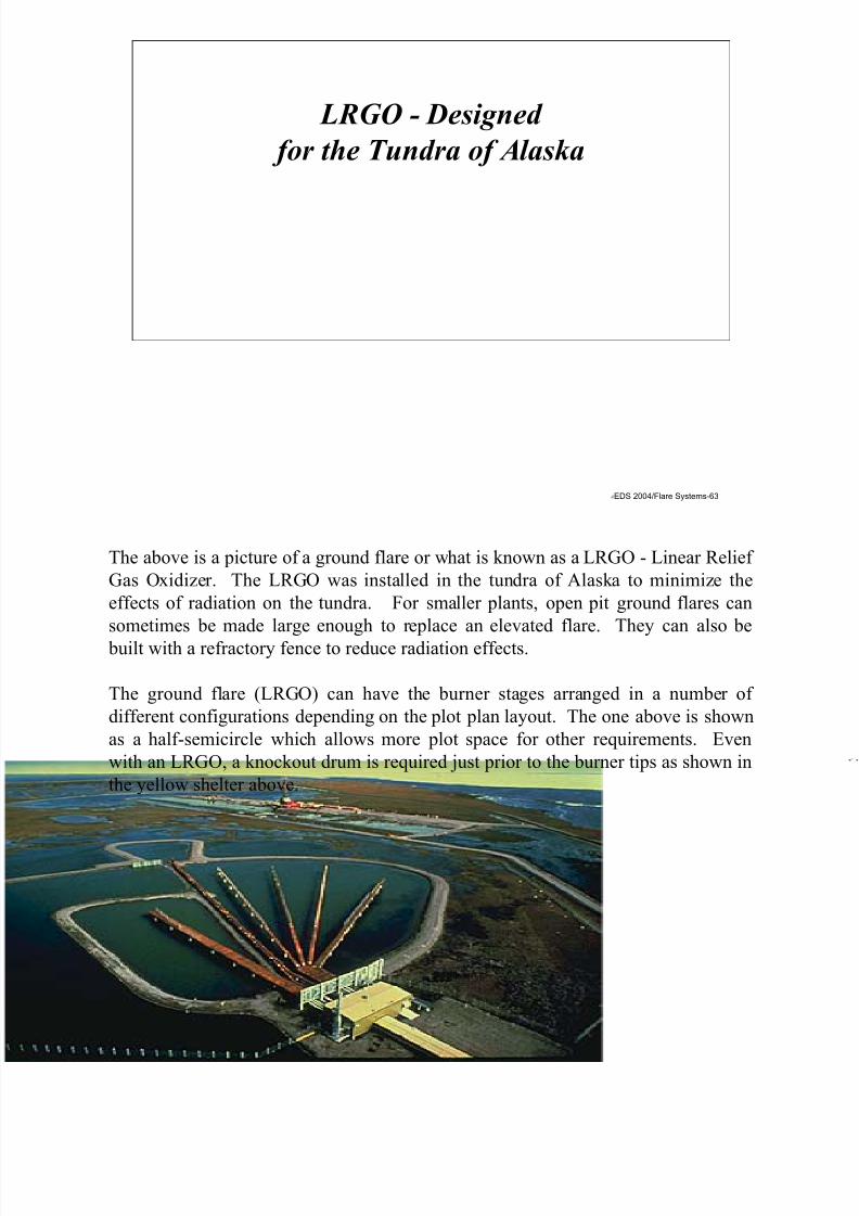
7/17/2019 Flare Systems
http://slidepdf.com/reader/full/flare-systems-568f385db390e 63/93
EDS 2004/Flare Systems-63
LRGO - Designed
for the Tundra of Alaska
The above is a picture of a ground flare or what is known as a LRGO - Linear Relief
Gas Oxidizer. The LRGO was installed in the tundra of Alaska to minimize the
effects of radiation on the tundra. For smaller plants, open pit ground flares can
sometimes be made large enough to replace an elevated flare. They can also be
built with a refractory fence to reduce radiation effects.
The ground flare (LRGO) can have the burner stages arranged in a number of
different configurations depending on the plot plan layout. The one above is shown
as a half-semicircle which allows more plot space for other requirements. Even
with an LRGO, a knockout drum is required just prior to the burner tips as shown in
the yellow shelter above.

7/17/2019 Flare Systems
http://slidepdf.com/reader/full/flare-systems-568f385db390e 64/93
EDS 2004/Flare Systems-64
Ground Flare Designed in Mexico
Open ground flares can have a variety of configurations. Some have many small
burners that together can flare large quantities of relief gas, such as the one shown
above. Their capacity is limited by the available plot area to distribute the burners.
The individual burners are fully smokeless, using the kinetic energy of the flare gas
to entrain enough air for complete stoichiometric combustion.
The disadvantage of ground flares is that they require pressure at the flare tip of
about 7 psig. This is much greater than the typical elevated flare. Rows of burners
are staged using control valves, so that the proper pressure is maintained at the
burners. As flow rate increases, the header pressure increases and more burners are
made available.
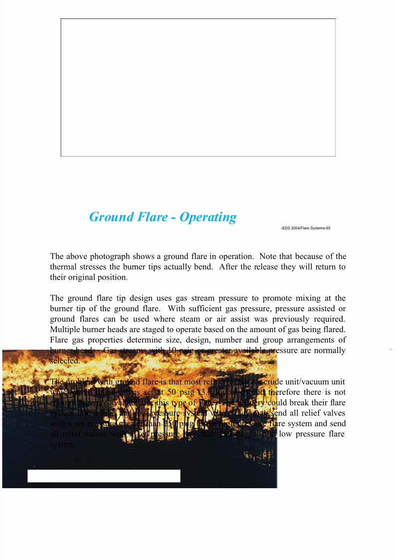
7/17/2019 Flare Systems
http://slidepdf.com/reader/full/flare-systems-568f385db390e 65/93
EDS 2004/Flare Systems-65
Ground Flare - Operating
The above photograph shows a ground flare in operation. Note that because of the
thermal stresses the burner tips actually bend. After the release they will return to
their original position.
The ground flare tip design uses gas stream pressure to promote mixing at the
burner tip of the ground flare. With sufficient gas pressure, pressure assisted or
ground flares can be used where steam or air assist was previously required.
Multiple burner heads are staged to operate based on the amount of gas being flared.
Flare gas properties determine size, design, number and group arrangements of
burner heads. Gas streams with 10 psig or greater available pressure are normally
selected.
The problem with ground flare is that most refineries have a crude unit/vacuum unit
which have relief valves set at 50 psig (3.5 kg/cm2g) and therefore there is notenough pressure available for this type of flare. The refinery could break their flare
system into a high and low pressure system where they may send all relief valves
with a set pressure greater than 250 psig to the high pressure flare system and send
all relief valves with a set pressure less than 250 psig to the low pressure flare
system.
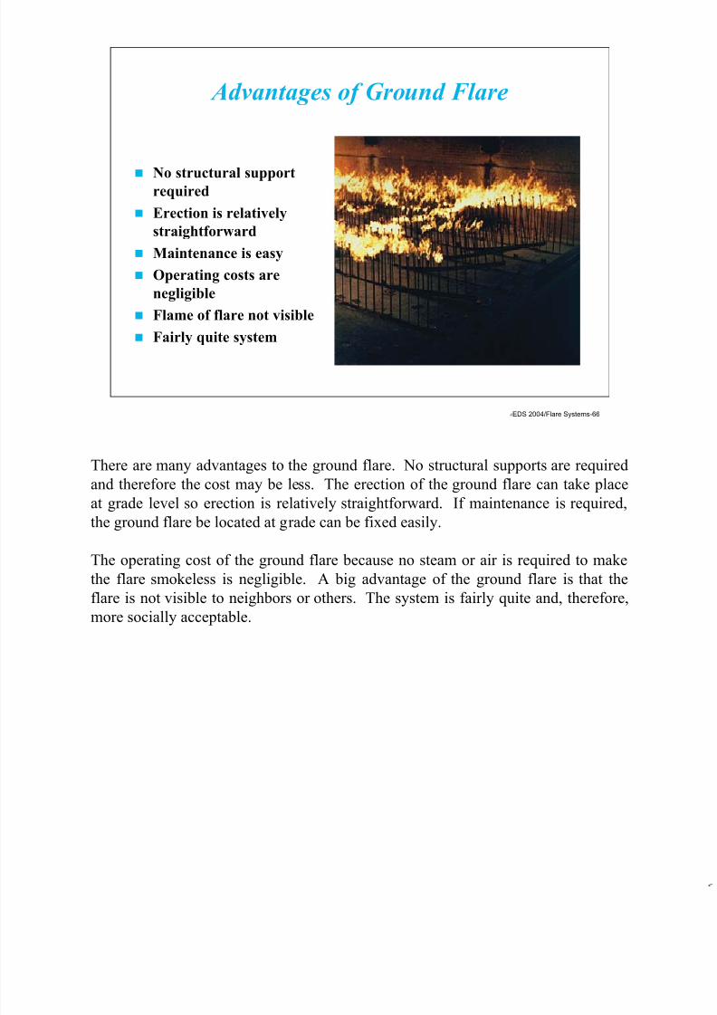
7/17/2019 Flare Systems
http://slidepdf.com/reader/full/flare-systems-568f385db390e 66/93
EDS 2004/Flare Systems-66
No structural supportrequired
Erection is relatively
straightforward
Maintenance is easy
Operating costs are
negligible
Flame of flare not visible
Fairly quite system
Advantages of Ground Flare
There are many advantages to the ground flare. No structural supports are required
and therefore the cost may be less. The erection of the ground flare can take place
at grade level so erection is relatively straightforward. If maintenance is required,
the ground flare be located at grade can be fixed easily.
The operating cost of the ground flare because no steam or air is required to make
the flare smokeless is negligible. A big advantage of the ground flare is that the
flare is not visible to neighbors or others. The system is fairly quite and, therefore,
more socially acceptable.

7/17/2019 Flare Systems
http://slidepdf.com/reader/full/flare-systems-568f385db390e 67/93
EDS 2004/Flare Systems-67
Must be well isolated
from the rest of the
refinery
Requires considerable
space and long
interconnecting
piping
Combustion takes
place on ground
Concentration of toxic
gas at grade mayremain high
Disadvantages of Ground Flares
The disadvantage of ground flare is that they must be isolated from the rest of the
refinery. In elevated flares, depending on the radiation profile, the flare may be
located near the process units. As can be seen from the above photograph, the
ground flare requires considerable space and long inter connecting piping resulting
in a lot of capital cost.
A big disadvantage is that the combustion takes place on the ground so therefore the
concentration of toxic gas at grade may remain high for some time after a release.
Drainage must also be considered.
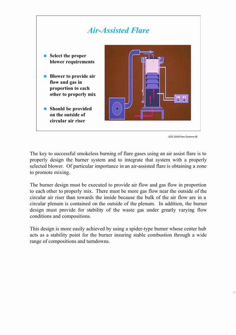
7/17/2019 Flare Systems
http://slidepdf.com/reader/full/flare-systems-568f385db390e 68/93
EDS 2004/Flare Systems-68
Select the proper
blower requirements
Blower to provide air
flow and gas in
proportion to each
other to properly mix
Should be provided
on the outside of
circular air riser
Air-Assisted Flare
The key to successful smokeless burning of flare gases using an air assist flare is to
properly design the burner system and to integrate that system with a properly
selected blower. Of particular importance in an air-assisted flare is obtaining a zone
to promote mixing.
The burner design must be executed to provide air flow and gas flow in proportion
to each other to properly mix. There must be more gas flow near the outside of the
circular air riser than towards the inside because the bulk of the air flow are in a
circular plenum is contained on the outside of the plenum. In addition, the burner
design must provide for stability of the waste gas under greatly varying flow
conditions and compositions.
This design is more easily achieved by using a spider-type burner whose center hub
acts as a stability point for the burner insuring stable combustion through a widerange of compositions and turndowns.

7/17/2019 Flare Systems
http://slidepdf.com/reader/full/flare-systems-568f385db390e 69/93
EDS 2004/Flare Systems-69
Qualitative sense decibels(dB) describe the loudness
of sound and noise.
– Whisper = 20 dBA
– Conversation = 65 dBA
– Food Blender = 88 dBA
– Motorcycle = 100 dBA
OSHA requires equipment
to have <85dBA over 8
hour period
Quiet Flare (Low Noise)
Significant disadvantages of steam usage are the increase noise and cost. Steam
aggravates the flare noise problem by producing high-frequency jet noise. The jet
noise can be reduced by the use of small multiple steam jets and, if necessary, by
acoustical shrouding. Steam injection is usually controlled manually with the
operator observing the flare (either directly or on a television monitor) and adding
steam as required to maintain smokeless operation.
To optimize steam usage, infrared sensors are available that sense flare flame
characteristics and adjust the steam flow rate automatically to maintain smokeless
operation. Automatic control, based on flare gas flow and flame radiation, gives a
faster response to the need for steam and a better adjustment of the quantity
required. If a manual system is used, steam metering should be installed to
significantly increase operator awareness and reduce steam consumption.

7/17/2019 Flare Systems
http://slidepdf.com/reader/full/flare-systems-568f385db390e 70/93
EDS 2004/Flare Systems-70
Multi-stage burners
system in enclosed ground
flares injects the auxiliary
fuel separately from the
vapor
Burner features a
refractory tile to maintain
flame stability and
promote mixing
Three T’s - Time,
Temperature andTurbulence
Enclosed Ground Flares
Enclosed ground flares incorporate a multi-stage burner system that injects the
auxiliary fuel separately from the vapor. The burner features a refractory tile in an
aerodynamically designed configuration to maintain flame stability and promote
mixing at much higher local temperatures that can be achieved by merely dumping
fuel in a mainly nitrogen or CO2 fume stream.
A unique “flame holder” design for the flame arrestor burner tip that accomplishes
this as well as creating excellent flame stability when auxiliary fuel is used.
EPA places significant emphasis on the effect of time, temperature, and turbulence.
Enclosed ground flares incorporates a high performance fin plate burner which can
handle most unsaturated gases smokelessly, without the cost of additional utilities.
Improved air management is achieved utilizing an advanced fluidic windfence, theresult of extensive research using wind tunnel technology. The system gives an
unrivalled level of smokeless operation, low burner and refractory temperatures,
low noise, and the flexibility of high turndown.
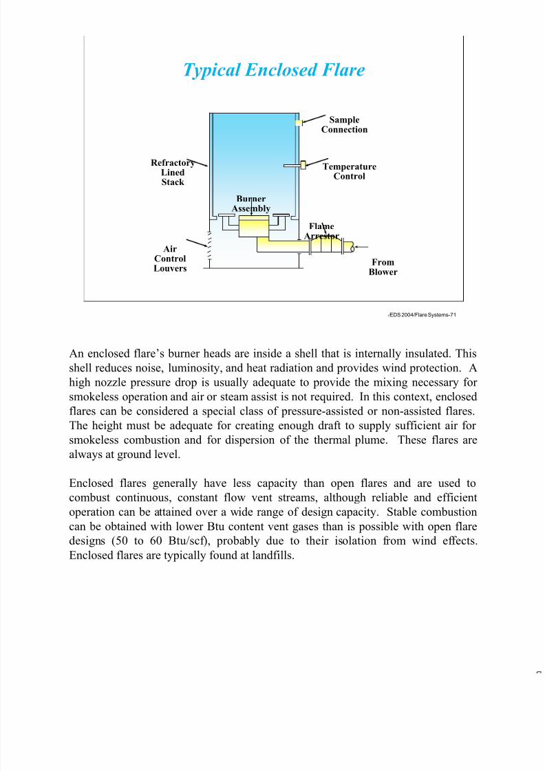
7/17/2019 Flare Systems
http://slidepdf.com/reader/full/flare-systems-568f385db390e 71/93
EDS 2004/Flare Systems-71
RefractoryLinedStack
AirControl
Louvers
BurnerAssembly
SampleConnection
TemperatureControl
FlameArrestor
From
Blower
Typical Enclosed Flare
An enclosed flare’s burner heads are inside a shell that is internally insulated. This
shell reduces noise, luminosity, and heat radiation and provides wind protection. A
high nozzle pressure drop is usually adequate to provide the mixing necessary for
smokeless operation and air or steam assist is not required. In this context, enclosed
flares can be considered a special class of pressure-assisted or non-assisted flares.
The height must be adequate for creating enough draft to supply sufficient air for
smokeless combustion and for dispersion of the thermal plume. These flares are
always at ground level.
Enclosed flares generally have less capacity than open flares and are used to
combust continuous, constant flow vent streams, although reliable and efficient
operation can be attained over a wide range of design capacity. Stable combustion
can be obtained with lower Btu content vent gases than is possible with open flare
designs (50 to 60 Btu/scf), probably due to their isolation from wind effects.Enclosed flares are typically found at landfills.
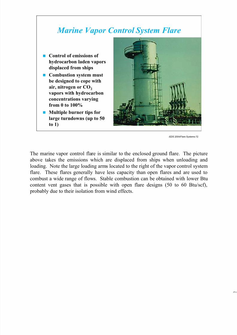
7/17/2019 Flare Systems
http://slidepdf.com/reader/full/flare-systems-568f385db390e 72/93
EDS 2004/Flare Systems-72
Control of emissions of
hydrocarbon laden vapors
displaced from ships
Combustion system must
be designed to cope with
air, nitrogen or CO2
vapors with hydrocarbon
concentrations varying
from 0 to 100%
Multiple burner tips for
large turndowns (up to 50to 1)
Marine Vapor Control System Flare
The marine vapor control flare is similar to the enclosed ground flare. The picture
above takes the emissions which are displaced from ships when unloading and
loading. Note the large loading arms located to the right of the vapor control system
flare. These flares generally have less capacity than open flares and are used to
combust a wide range of flows. Stable combustion can be obtained with lower Btu
content vent gases that is possible with open flare designs (50 to 60 Btu/scf),
probably due to their isolation from wind effects.

7/17/2019 Flare Systems
http://slidepdf.com/reader/full/flare-systems-568f385db390e 73/93
EDS 2004/Flare Systems-73
Achieve high destruction
efficiencies through the
loading cycle
Systems range in size
from 100 BPH to 25,000
BPH
Enclosed burners can be
easily tested for
emissions
Truck Loading Vapor Control Flare
Truck loading terminal flares are designed to burn waste gas streams which can
range from very lean (high oxygen/nitrogen content) to very rich (high hydrocarbon
content). The design heat release turndown is often 10 to 1. The rich steams
require forced air blowers to supply part of the combustion air to produce
turbulence in the flame zone for smokeless burning.
The lean streams can be extinguished (blown out) by the forced air blowers if they
are not properly controlled. Most systems have two-speed blowers, one for each
stage’s burners, a two speed quench air blower for efficient temperature control, and
all necessary instrumentation and controls to automatically maintain stable,
smokeless combustion in the unit.
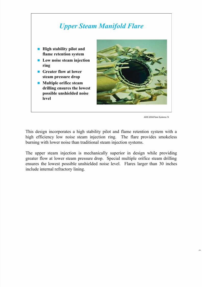
7/17/2019 Flare Systems
http://slidepdf.com/reader/full/flare-systems-568f385db390e 74/93
EDS 2004/Flare Systems-74
High stability pilot andflame retention system
Low noise steam injection
ring
Greater flow at lower
steam pressure drop
Multiple orifice steam
drilling ensures the lowest
possible unshielded noise
level
Upper Steam Manifold Flare
This design incorporates a high stability pilot and flame retention system with a
high efficiency low noise steam injection ring. The flare provides smokeless
burning with lower noise than traditional steam injection systems.
The upper steam injection is mechanically superior in design while providing
greater flow at lower steam pressure drop. Special multiple orifice steam drilling
ensures the lowest possible unshielded noise level. Flares larger than 30 inches
include internal refractory lining.

7/17/2019 Flare Systems
http://slidepdf.com/reader/full/flare-systems-568f385db390e 75/93
EDS 2004/Flare Systems-75
Stranded natural gas, so named
because no pipelines exists to
transport it, is most prevalent
(red) in Africa, Middle East,
Asia, and Europe
Ultimate energy irony: Clean,
plentiful gas fuel wasted because
it blocks access to a dirty, liquid
one
Syntroleum process, natural gas
reacts via a catalyst to oxygen in
the air to form a synthetic gas
(Syngas) then a second reactioncoverts Syngas to a liquid diesel
fuel
Designer Fuels
Stranded gas sites around the world where no pipeline is available to capture and
transport natural gas, it is vented and fired. The worldwide supply of stranded
natural gas equals all the know U.S. petroleum reserves. It a huge potential
resource, disposed of in a most wasteful way. But a new method of capturing it
means it could soon be powering the car you drive.
In the Syntroleum process, natural gas reacts via a catalyst to oxygen in the air to
form a synthetic gas (hydrogen/nitrogen/carbon monoxide), which is dubbed
Syngas. A second reaction converts Syngas to a liquid diesel fuel that would power
special high-efficiency, clean-burning diesel engines. The byproducts are water,
nitrogen, and carbon dioxide.
Much of the incentive to create new fuels stems from the limitations of today’s
catalytic converters, which have proven to be a major boon to clean air - today'scars are approximately 99 percent cleaner than their 1960s counter parts, according
to the American Automobile Association - but now stand in the way of highly fuel
efficient engines. The reason lies with how catalysts clean exhaust.

7/17/2019 Flare Systems
http://slidepdf.com/reader/full/flare-systems-568f385db390e 76/93
EDS 2004/Flare Systems-76FS-R00-27
IgnitorTubes
IgnitorManifold
PilotManifold
PilotGas
Compressed
AirIgnitor
Gas
Flame FrontIgnitor Panel
Pilots with Thermocouples
Gas AssistedFlare Burner
w/ Fluidic Seal
Assist Gas
FlowSensor
FERelief & Vent Header
AmmoniaStorageTanks
Purge
GasInjection
Relief Valves
ManualVents
NH 3 Plant
The above diagram is that of an ammonia plant. Ammonia is a problem with flare
systems because of its low heating value. Ammonia does not burn very effectively
and therefore requires assist gas. This is also required because of EPA requirements
with flares. As can be seen from the above diagram, there assist gas is added based
on the flow rate from the ammonia storage tanks and other relief valves.
The flow sensor will increase the assist gas flow rates proportionally with the
increase in ammonia flow rates. A Net lower heating value of approximately 300 to
1000 Btu/scf is required as defined in 40 CFR 60.18, which was discussed earlier in
the material. The flare utilized for this ammonia is a gas assisted flare. This means
that there is some high pressure gas available within the plant. Steam is not the
preferred choice for the ammonia flare. The flame front igniter panel is also
utilized in the ammonia flare.

7/17/2019 Flare Systems
http://slidepdf.com/reader/full/flare-systems-568f385db390e 77/93
EDS 2004/Flare Systems-77
Auxiliary fuel requiredin ammonia flares
Auxiliary fuel to
combust hydrocarbon
vapors when a clean
flare gas falls below the
necessary heating value
Picture to the right is
one of an ammonia
plant
Ammonia (NH 3 ) Plant Considerations
Ammonia plants are a unique application for a flare. The only time a flare is needed
is during a power or refrigeration failure. Normally the gas is contained in a low-
pressure refrigerated storage tank and dispensed on to railroad cars or tank trucks
usually bound for fertilizer or metallurgical process applications. In most instances,
there are not releases of any kind from an ammonia plant. However, if a power or
refrigeration failure occurs, the pressure in the tank will gradually build up.
A short-term power failure or a minor refrigeration failure will not result in the flare
operating, since the tank is well insulated and the problem can be corrected quickly.
The flare, however, is the final safeguard. The ignition system has a built-in battery
backup system that can still activate and ignite the pilot in the event of a power
failure.
Since ammonia has a very low heating value, it is necessary to administrate assistgas to make the ammonia burn effectively.

7/17/2019 Flare Systems
http://slidepdf.com/reader/full/flare-systems-568f385db390e 78/93
EDS 2004/Flare Systems-78
Flame FrontIgnitor Panel
Compressed Air
Ignitor Gas
Oil
IgnitorTubes
Pilots
Ignitor
ManifoldPilot
Manifold
Water Assisted
SmokelessFlare Burnerw/Fluidic Seal
Boom
Water Assist
Pilot GasGas
DisentrainmentDrum
Offshore Platform
The above drawing is an offshore platform layout and in the requirements for a flare
system. One of the first items one notices is the large boom required for the flare.
The purpose of the boom is to keep the flames and radiation produced away from
the workers on the offshore platform. The type of flare shown is a water assisted
flare. Since steam is not available and air is expensive, the most effective method
to make the flare smokeless is to use water from the sea.
When designing a flare for an offshore platform, one should consider the worst case
for gas flow. In addition, to reduce the cost of the boom, accurate radiation
calculations need to be made.
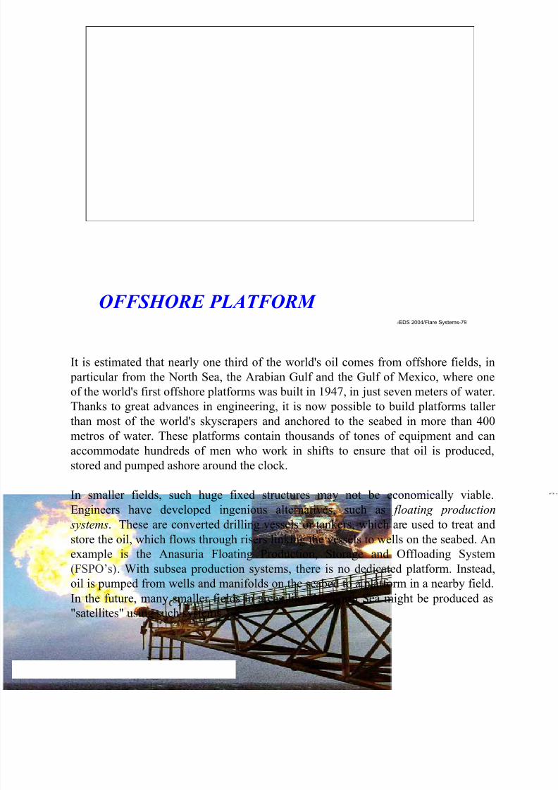
7/17/2019 Flare Systems
http://slidepdf.com/reader/full/flare-systems-568f385db390e 79/93
EDS 2004/Flare Systems-79
OFFSHORE PLATFORM
It is estimated that nearly one third of the world's oil comes from offshore fields, in
particular from the North Sea, the Arabian Gulf and the Gulf of Mexico, where one
of the world's first offshore platforms was built in 1947, in just seven meters of water.
Thanks to great advances in engineering, it is now possible to build platforms taller
than most of the world's skyscrapers and anchored to the seabed in more than 400
metros of water. These platforms contain thousands of tones of equipment and can
accommodate hundreds of men who work in shifts to ensure that oil is produced,
stored and pumped ashore around the clock.
In smaller fields, such huge fixed structures may not be economically viable.
Engineers have developed ingenious alternatives, such as floating production
systems. These are converted drilling vessels or tankers, which are used to treat and
store the oil, which flows through risers linking the vessels to wells on the seabed. An
example is the Anasuria Floating Production, Storage and Offloading System(FSPO’s). With subsea production systems, there is no dedicated platform. Instead,
oil is pumped from wells and manifolds on the seabed to a platform in a nearby field.
In the future, many smaller fields in areas like the North Sea might be produced as
"satellites" using such systems.
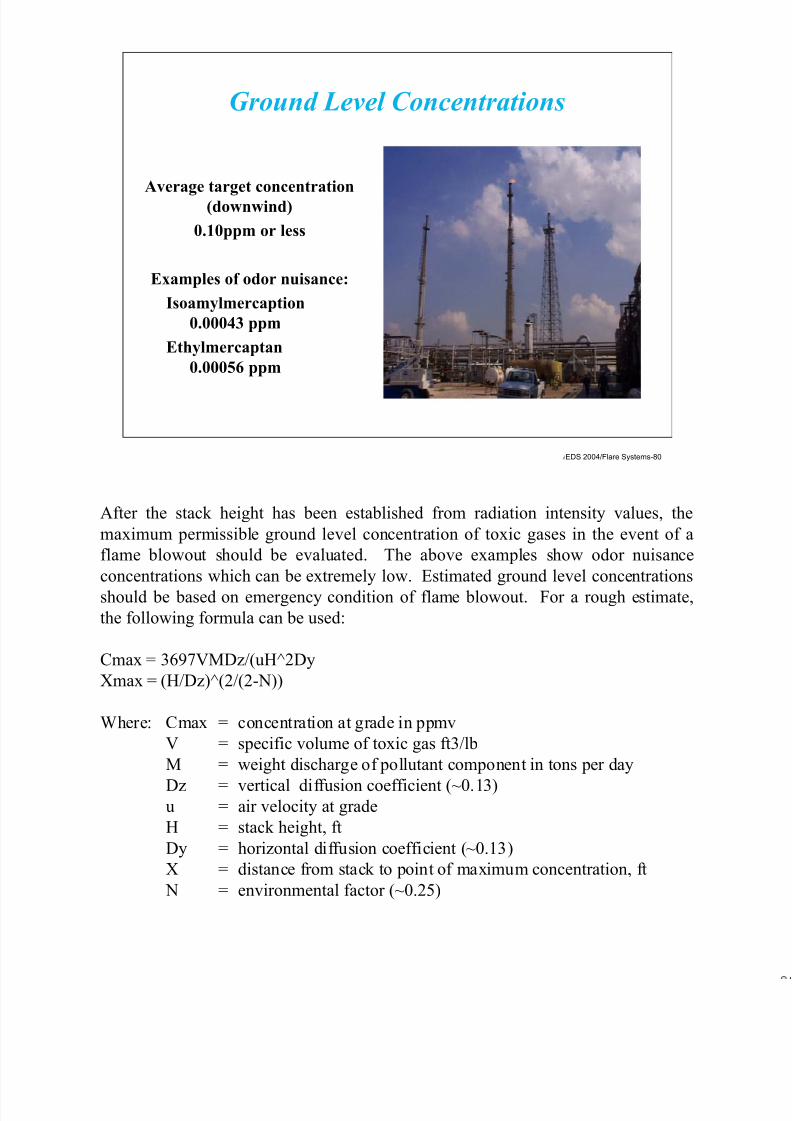
7/17/2019 Flare Systems
http://slidepdf.com/reader/full/flare-systems-568f385db390e 80/93
EDS 2004/Flare Systems-80
Average target concentration
(downwind)
0.10ppm or less
Examples of odor nuisance:
Isoamylmercaption
0.00043 ppm
Ethylmercaptan
0.00056 ppm
Ground Level Concentrations
After the stack height has been established from radiation intensity values, the
maximum permissible ground level concentration of toxic gases in the event of a
flame blowout should be evaluated. The above examples show odor nuisance
concentrations which can be extremely low. Estimated ground level concentrations
should be based on emergency condition of flame blowout. For a rough estimate,
the following formula can be used:
Cmax = 3697VMDz/(uH^2Dy
Xmax = (H/Dz)^(2/(2-N))
Where: Cmax = concentration at grade in ppmv
V = specific volume of toxic gas ft3/lb
M = weight discharge of pollutant component in tons per day
Dz = vertical diffusion coefficient (~0.13)u = air velocity at grade
H = stack height, ft
Dy = horizontal diffusion coefficient (~0.13)
X = distance from stack to point of maximum concentration, ft
N = environmental factor (~0.25)
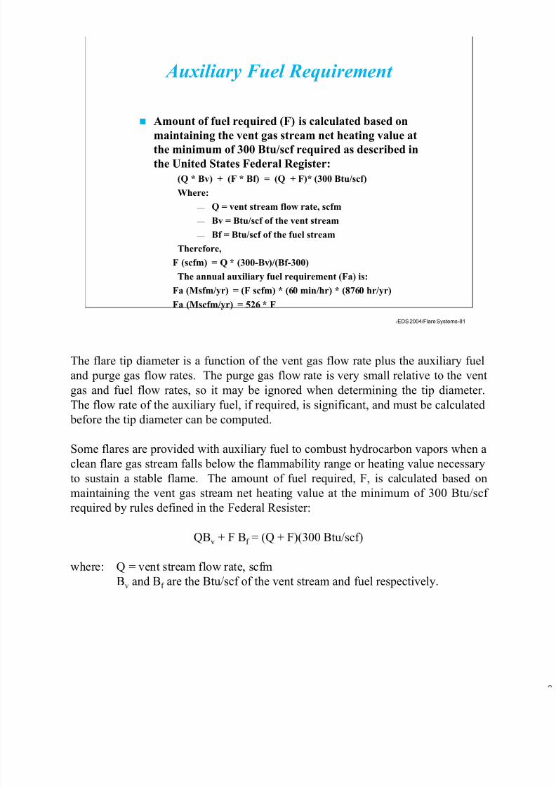
7/17/2019 Flare Systems
http://slidepdf.com/reader/full/flare-systems-568f385db390e 81/93
EDS 2004/Flare Systems-81
Amount of fuel required (F) is calculated based on
maintaining the vent gas stream net heating value atthe minimum of 300 Btu/scf required as described in
the United States Federal Register:
(Q * Bv) + (F * Bf) = (Q + F)* (300 Btu/scf)
Where:
— Q = vent stream flow rate, scfm
— Bv = Btu/scf of the vent stream
— Bf = Btu/scf of the fuel stream
Therefore,
F (scfm) = Q * (300-Bv)/(Bf-300)
The annual auxiliary fuel requirement (Fa) is:
Fa (Msfm/yr) = (F scfm) * (60 min/hr) * (8760 hr/yr)
Fa (Mscfm/yr) = 526 * F
Auxiliary Fuel Requirement
The flare tip diameter is a function of the vent gas flow rate plus the auxiliary fuel
and purge gas flow rates. The purge gas flow rate is very small relative to the vent
gas and fuel flow rates, so it may be ignored when determining the tip diameter.
The flow rate of the auxiliary fuel, if required, is significant, and must be calculated
before the tip diameter can be computed.
Some flares are provided with auxiliary fuel to combust hydrocarbon vapors when a
clean flare gas stream falls below the flammability range or heating value necessary
to sustain a stable flame. The amount of fuel required, F, is calculated based on
maintaining the vent gas stream net heating value at the minimum of 300 Btu/scf
required by rules defined in the Federal Resister:
QBv + F Bf = (Q + F)(300 Btu/scf)
where: Q = vent stream flow rate, scfm
Bv and Bf are the Btu/scf of the vent stream and fuel respectively.

7/17/2019 Flare Systems
http://slidepdf.com/reader/full/flare-systems-568f385db390e 82/93
EDS 2004/Flare Systems-82
Sizing must also comply with Federal Register (40 CFR 60.18)
for maximum velocity of steam-assisted, elevated flares:
It is standard practice to size the flare so that the design velocity
of flow rate Qtot, is 80 percent of Vmax:
Dmin (in) = 12*[((4/PI)(Qtot/60sec/min))/(0.8*Vmax)]^0.5
Dmin (in) = 1.95 * (Qtot/Vmax)^0.5
Where:
Qtot = Q + F (measured at stream temperature and pressure)
Dmin should be rounded up to the next largest available
commercial size
Flare Tip Diameter
Net Heating Value of Vent Stream
Bv (Btu/scf)
Maximum Velocity
Vmax (ft/sec)
300300-1000
> 1000
60log10(Vmax) = (Bv + 1214)852
400
Rearranging gives
F (scfm) = Q * (300 - Bv)/(Bf - 300)
The annual auxiliary fuel requirement, Fa, is calculated by:
Fa (Mscfm/yr) = (F scfm)(60 min/hr)(8760 hr/yr)
Fa (Mscfm/yr) = 526F
Typical natural gas has a net heating value of about 1,000 Btu/scf. Automatic
control of the auxiliary fuel is ideal for processes with large fluctuations in VOC
composition. These flares are used for the disposal of such streams as sulfur tail
gases and ammonia waste gases, as well as any low Btu vent streams.
7/17/2019 Flare Systems
http://slidepdf.com/reader/full/flare-systems-568f385db390e 83/93
EDS 2004/Flare Systems-83
Wind
FlareLP Zone
Gas Jet
Supplementary Energy
High ExitVelocity
Low ExitVelocity
Low Exit VelocityWith SecondaryEnergy Source
W W W
F
F
G G G
FLL LS
W =
F =LP =
G =
S =
Improve Flare Burner LifeVector Diagrams
The above diagram shows how steam (supplementary energy) injected into the flare
tip can improve the flame tilt. Pressure drops as large as 2 psig have been
satisfactorily used at the flare tip.
Too low a tip velocity can cause heat and corrosion damage. The burning of the
gases becomes quite slow, and the flame is greatly influenced by the wind. The
low-pressure area on the downwind side of the stack may cause the burning gases to
be drawn down along the stack for 10 feet (3 meters) or more. Under these
conditions, corrosive materials in the stack gases may attack the s

7/17/2019 Flare Systems
http://slidepdf.com/reader/full/flare-systems-568f385db390e 84/93
EDS 2004/Flare Systems-84
Mechanism
– Oxidation reaction
Factors
– Time, temperature
and turbulence
Incinerator Design
Incinerators are called thermal oxidizers, combustors and thermal reactors. The
function of an incinerator is the destruction of organic and inorganic wastes using
an oxidation reaction. The products of combustion are Carbon monoxide Nox, Sox,
acid gases, particulate and unburned hydrocarbon. The carbon monoxide are
generally a function of burner operation and the unburned hydrocarbon and SOX
and acid gases generally a function of incinerator operation.
There are many permit requirements such as tons per year that can be emitted and
ppm that can be discharged. The equipment shall be designed for the worst case
scenario if limited by an hourly average ppm level. A tons per year emission limit
may allow designing for a normal case, while merely handling an infrequent or
intermittent surge.
The waste characterization determines the type of incinerator. The burner selectionis dependent on waste type and special consideration such as low NOX. The
incinerator design for introduction of some waste must provide for retention time.
Flue gas treatment may be necessary to meet the required emissions levels if
particulate or acid gases are present in fuel gas.

7/17/2019 Flare Systems
http://slidepdf.com/reader/full/flare-systems-568f385db390e 85/93
EDS 2004/Flare Systems-85
Burners
– Ignite the fuel and
organic material
Chamber
– Appropriate residence
time
for oxidation process
Three T’s of Combustion
– Temperature
– Time – Turbulence
Principles of Combustion
Some process design consideration are low waste gas pressure drop of 4” w.c. and
NOX requirements because of high fuel rate. The mechanical design consideration
for natural draft and for forced draft must be considered. Natural draft is less
expense, forced draft provides better turndown, and forced draft is better for adding
heat recovery .
The layout of the incinerator must be considered. Is horizontal better than vertical?
The cost of the vertical unit is less expensive, the vertical unit requires less plot
space. The horizontal is easier to access and add downstream equipment. If the
heat release is large, then the horizontal may be required to eliminate impingement.
The refractory of brick castable or blanket must be considered. Highly abrasive
particulate requires special castable or brick. The blanket has limited velocity
capability. The blanket provides ability for on/off operation and heat up and alsocosts less.

7/17/2019 Flare Systems
http://slidepdf.com/reader/full/flare-systems-568f385db390e 86/93
EDS 2004/Flare Systems-86
100
80
60
40
20
0600 800 1000 1200 1400 1600 1800 2000
1 sec
1.0 sec0.01 sec
IncreasingResidence
Time
Increasing Temperature, °F
0.001 sec
P o l l u t a n t D e s t r u c t i o n ,
%
Residence time of gases in combustion chamber calculated from: t = V/Qt = Residence Time (s)v = Chamber Volume (ft3)Q = Gas volumetric flow rate at combustion conditions (ft3/s)
Coupled Effects of Temperature andTime on Rate of Pollutant Oxidation
The above chart is the coupled effects of the three T’s of temperature, time and
turbulence on the rate of pollutant oxidation. By increasing temperature only and
holding the retention time, the same increases the pollutant destruction efficiency.
By increasing the retention time only and maintaining the same temperature
increases the pollutant destruction. Depending on the percent pollutant destruction
required determines what temperature is required in the incinerator and how long of
a residence time is required.
Therefore, for the same gas volumetric flow at combustion conditions, a higher
temperature and lower retention time or a lower temperature and higher retention
time may be the more optimum design for the incinerator.
7/17/2019 Flare Systems
http://slidepdf.com/reader/full/flare-systems-568f385db390e 87/93
EDS 2004/Flare Systems-87
Fume
Exhaust
Combustion
Air
(Fume)
Fuel
Schematic of a Thermal Incinerator
The above drawing is a schematic of a thermal incinerator. As you can see from the
drawing, the waste gas or fume is introduced at the top left hand corner.
Combustion air and fuel are added to ignite the mixture. The time it takes for the
fume to enter and leave the incinerator as exhaust is know as the retention time.
The temperature in the incinerator is the number used in calculating the efficiency.
You can also see the turbulence when the air, fuel and fume are combined within
the incinerator.
Using low NOX burners or 2 stage furnace (reducing then oxidizing), catalytic
NOX reduction or special scrubber may be required after the exhaust to maintain an
NOX ppm limit which is set by the local law and governments such as EPA.

7/17/2019 Flare Systems
http://slidepdf.com/reader/full/flare-systems-568f385db390e 88/93
EDS 2004/Flare Systems-88
ProductLoading Arm
Product fromStorage Tanks
Natural Gas/Inerting Gas
EnrichingDetonation
Arrestor
Hydrocarbon Vapor to Control Device
Vapor Mover
SumpPump
Condensateto Tanks
DischargedVapors
Ship
or BargeDock Facilities Shoreside Facilities
GasAnalyzer
Vapor Arm
KnockoutDrum(s)
Typical Marine Vessel Loading System
To achieve high destruction efficiencies through the loading cycle requires that
provision be made to keep the combustor at a minimum temperature prior to
introducing loading vapors and during high vapor flow rates when the majority of
the vapor is air, nitrogen or carbon dioxide depending on the ship being loaded.
Achieving high destruction efficiencies requires that the oxygen in the combustion
air be given adequate opportunity to come in contact with hydrocarbons which can
be a very low percentage of an inert vapor stream. Mixing is critical to making this
happen. The more time the vapor stream is at temperature in turbulent contact with
combustion air, the higher the likelihood of complete combustion which means no
carbon monoxide or hydrocarbons. The less combustion air that is required (excess
air) to achieve complete combustion, the less auxiliary fuel is required to maintain
temperate. This is especially important when dealing with very low Btu content
vapors associated with inert vessels or non inert ships that use inerting techniques to
meet the Coast Guard safety criterion. The design of the combustion equipment,which accounts for approximately 20% of the total marine terminal equipment cost,
is influenced by the emission rules. Due to the cyclic nature of the use pattern of
combustors in marine service, ceramic fiber is generally the refractory system of
choice due to its low heat capacitance and resistance to thermal shock. These units
are routinely brought from ambient to 1500°F in less than 5 minutes.
7/17/2019 Flare Systems
http://slidepdf.com/reader/full/flare-systems-568f385db390e 89/93
EDS 2004/Flare Systems-89
Gasoline Vapors
Crude Vapors
Percent of Storage Tank or Truck Filled
70
60
50
40
30
20
00 25 50 75 100
T o t a l H y d r o c a r b o n V a p o r
C o n c e n t r a t i o n i n V e s s e l
( V o l u m e P e r c e n t )
Storage Tank and Tank Truck Loading Hydrocarbon Concentration Profile
The loading occurs at the transportation loading rack, the vapor combustion system
is in a standby mode with no pilot flame, the vapor block valve is closed, and the air
assist blower is off. Automatic startup of the vapor combustion system is initiated
by an electrical signal from the loading rack that product loading will occur shortly.
The startup sequence consists of a short air purge using the air assist blower to
purge the air plenum of the open flare or the enclosed flare of any combustibles
prior to pilot ignition. This brief air purge is followed by automatic electronic
ignition of the pilot. After pilot ignition, product loading begins at the loading rack
and an air vapor mixture begins to flow from the transports being loaded to the
vapor combustion system.
Flow through the vapor combustion system first consists of the air vapor mixture
from the lading rack bubbling through a liquid seal. As soon as sufficient flow is
available, it will be detected by the pressure monitoring controls which willautomatically open the vapor block valve allowing the air vapor mixture to flow
thorough the flame arrestor to the burner, where the combustible vapors are ignited
by the pilot and burned. The air assist blower provides partial combustion air and
mixing energy to the burner tips to assure smokeless combustion. As the loading
operation at the loading rack is completed, vapor flow to the combustion system
decreases. The pressure monitoring system closes the vapor block valve when the
vapor flow is insufficient to maintain minimum burner velocity. The pilot and air
assist blower remain on for a brief time period after loading is complete. If no
further loading occurs, the combustion unit will shut down in the standby mode toawait automatic restart.

7/17/2019 Flare Systems
http://slidepdf.com/reader/full/flare-systems-568f385db390e 90/93
EDS 2004/Flare Systems-90
Gasoline Vapors
CrudeVapors
Percent of Marine Vessel Filled
70
60
50
40
30
20
00 25 50 75 100
T o t a l H y d r o c a r b o n V a p o r
C o n c e n t r a t i o n i n V e s s e l
( V o l u m e P e r c e n t )
10
Marine Vessel Loading Hydrocarbon Concentration Profile
As shown in the above chart, the hydrocarbon vapors are in higher concentration
during the final portion when the vessel is being filled. The vapors immediately
upon being transferred to the loading facility, are analyzed and conditioned, if
necessary, to assure they are well outside the explosive limit.
The combustion system must be designed to cope with air, nitrogen, and carbon
dioxide vapors with hydrocarbons concentrations varying from 0 to 100 percent.
The application must also deal with flow rates which are wetted, loaded and topped
off.
The large turndown (up to 100 to 1) encountered in marine terminals, satisfying the
low end velocity criteria makes it impossible in a single burner configuration to
have stable and efficient combustion at the high flow rates.
To accommodate the wide range of vapor flows, multiple burners are used and are
brought in and out of service to assure the flame arrestor tips are always kept cool
and that exit velocities never exceed the stability limit of the burner
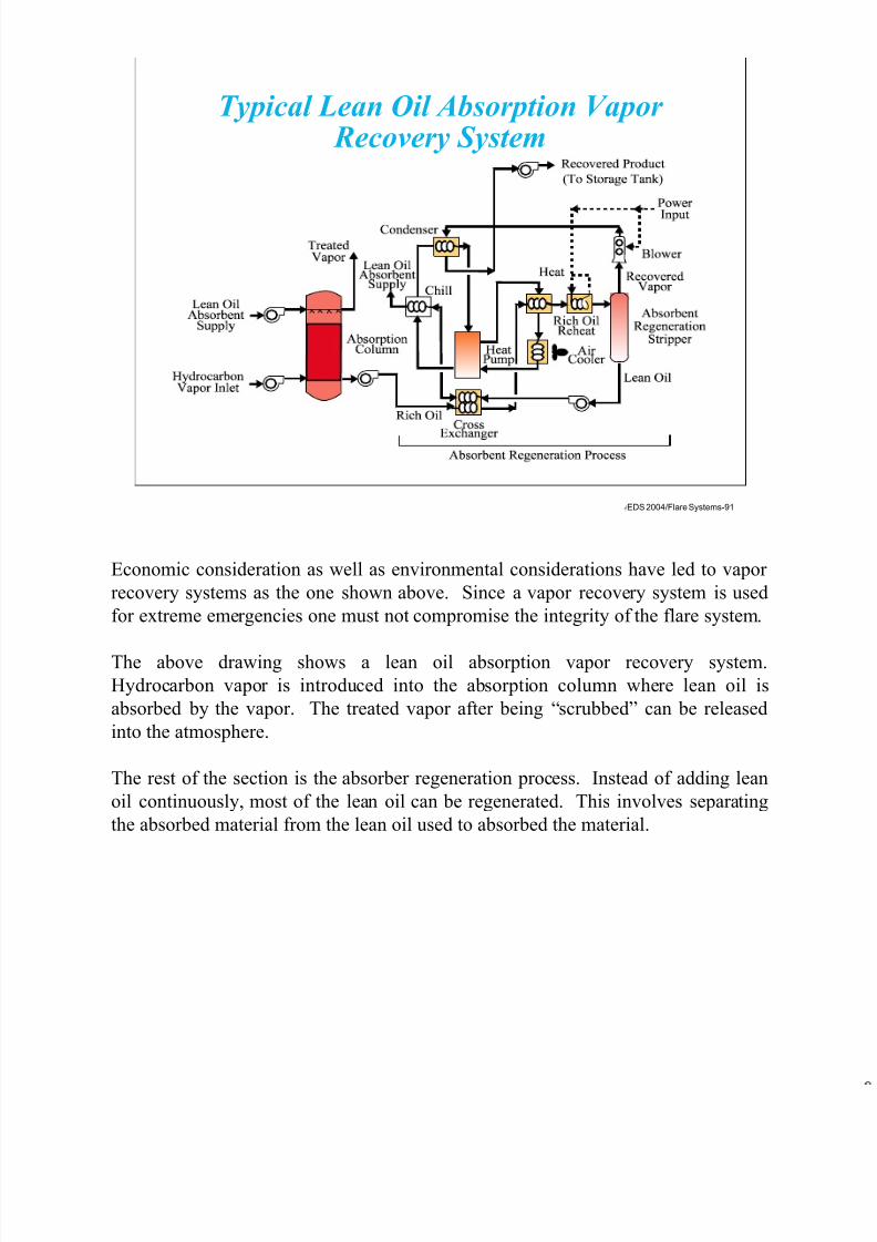
7/17/2019 Flare Systems
http://slidepdf.com/reader/full/flare-systems-568f385db390e 91/93
EDS 2004/Flare Systems-91
Typical Lean Oil Absorption Vapor Recovery System
Economic consideration as well as environmental considerations have led to vapor
recovery systems as the one shown above. Since a vapor recovery system is used
for extreme emergencies one must not compromise the integrity of the flare system.
The above drawing shows a lean oil absorption vapor recovery system.
Hydrocarbon vapor is introduced into the absorption column where lean oil is
absorbed by the vapor. The treated vapor after being “scrubbed” can be released
into the atmosphere.
The rest of the section is the absorber regeneration process. Instead of adding lean
oil continuously, most of the lean oil can be regenerated. This involves separating
the absorbed material from the lean oil used to absorbed the material.

7/17/2019 Flare Systems
http://slidepdf.com/reader/full/flare-systems-568f385db390e 92/93
EDS 2004/Flare Systems-92
Precooler Vapor CondensingUnit (Evaporator)
ThermostaticExpansion
Valve
CompressedRefrigerant
Compressor-Condensor
Power Input
RecoveredProduct
CondensateCollection Tank
Power
Input
TreatedVapor
Blower
HydrocarbonVapor Inlet
FreonReturn
Typical Refrigeration Vapor Recovery System
The above drawing is a refrigeration vapor recovery system. The hydrocarbon
vapors are precooled and then sent to a vapor condensing unit or what is know as an
evaporator. The hydrocarbons will condense once it fall below its dew point. The
product that condenses is stored in a condensate collection tank before being sent
back to the process unit for reprocessing.
The treated vapors from the condensate collection tank are sent to the atmosphere
by a blower. The refrigeration vapor recovery system is similar to that of a
refrigerator or an air conditioning unit which uses some type of freon depending on
the temperature the stream needs to be reduced to.
The disadvantage of the refrigeration vapor recovery system is the high cost of
electricity required for the system.

7/17/2019 Flare Systems
http://slidepdf.com/reader/full/flare-systems-568f385db390e 93/93
EDS 2004/Flare Systems-93
HydrocarbonVapor Inlet
TreatedVapor Out
Burner
CatalystBed
ThermalZone
OxidationZone
Preheat OptionalHeat
Recovery
Stack
FeedAir or
ProcessStream
HeatedAir or
ProcessStream
Typical Catalyst Oxidation System
The above drawing is that of a catalytic oxidation system. The hydrocarbon vapors
are fist preheated and then sent into the thermal zone of the oxidation system. After
being heated to over 1000°F, depending on the catalyst, it is sent through a catalyst
bed and the oxidation zone.
The vapors are then preheated against the hydrocarbon vapor air going into the
thermal section. The vapor are still going to be hot and then can be either sent back
to the process streams or an optional heat recovery unit can be installed.
After the heat recovery unit, the cooled treated vapor will be sent to a stack for final
disposal to the atmosphere.