Embed Size (px)
Citation preview

Installation, Operation, and Maintenance - EDC 322, Revision 3, Apr. 2021
1 of 21
SMITH VALVES, 13750 Hollister Road, Houston, Texas 77086 Tel: 713-590-1312, www.smithvalves.com
Installation, Operation, and Maintenance Manual
Flanged Ends, Gate, Globe, & Check Valves
Gate Valve Series: 0895/2595 Globe Valve Series: G895/G259
Ball Check Valve Series: 0B89/0B29/SB89/SB29 Piston Check Valve Series: 0C89/0C29/SC89/SC29
TNC Doc EDC 322, Revision 3, Issued Apr 2021
Installation, Operation, and Maintenance - EDC 322, Revision 3, Apr. 2021
2 of 21
SMITH VALVES, 13750 Hollister Road, Houston, Texas 77086 Tel: 713-590-1312, www.smithvalves.com
TABLE OF CONTENTS 1.0 - GENERAL
2.0 - INSTALLATION
3.0 - OPERATION
4.0 - MAINTENANCE
5.0 - BODY-BONNET/COVER BOLTING
6.0 - MAINTENANCE ON BOLTED BONNET GATE VALVES
7.0 - MAINTENANCE ON BOLTED BONNET GLOBE VALVES
8.0 - MAINTENANCE ON BOLTED CAP CHECK VALVES
9.0 - PWHT (POST WELD HEAT TREATMENT)
10.0 - NAMEPLATE
11.0 - TABLES
12.0 - VALVE COMPONENTS
13.0 - LIST OF APPENDICES
Installation, Operation, and Maintenance - EDC 322, Revision 3, Apr. 2021
3 of 21
SMITH VALVES, 13750 Hollister Road, Houston, Texas 77086 Tel: 713-590-1312, www.smithvalves.com
1.0 General
The majority of this information is common knowledge to experienced forged steel valve users. This information applies to all standard Smith API 602 Forged valves. When properly installed in applications for which they were designed, Smith Valves will provide long trouble-free service.
1.1 Responsibility for Valve Application
The End User is responsible for ordering the correct valves that are compatible with the application. Smith Valves are to be installed in the observance of the pressure rating and design temperature. Prior to installation, the valve and nameplate should be checked for proper identification to ensure that the valve is of the proper type, material, and is of a suitable pressure class and temperature limit to satisfy the application requirements.
1.2 Receiving, Inspection, and Handling
Valves should be inspected upon receipt to determine: • Compliance to purchase order requirements. • Correct type, pressure class, size, body and trim materials and end connections
(this information may be found on the nameplate or may be stamped on the body of the valve).
• Any damage caused during shipping and handling to end connections, handwheel, or stem.
We do recommend however that this entire document be read prior to proceeding with any installation or repair.
Do not use any valve in applications where either the pressure or temperature is higher than the allowable working values. Also, valves should not be used in service media if not compatible with the valve material of construction, as this will cause chemical attacks.
The End User is advised that misapplication of the product may result in injuries or property damage. A selection consistent with the particular performance requirements is important for proper application.
Installation, Operation, and Maintenance - EDC 322, Revision 3, Apr. 2021
4 of 21
SMITH VALVES, 13750 Hollister Road, Houston, Texas 77086 Tel: 713-590-1312, www.smithvalves.com
2.0 Installation
2.1 INSTALLATION
2.2 Installation Positions
Gate valves are usually bi-directional, and therefore may be installed in either direction. In some special cases, gate valves may be unidirectional, in which case the direction of flow will be indicated on the valve body.
Globe and Check valves are unidirectional and have the direction of flow indicated on the valve body.
Smith piston and ball check valves are recommended for use only in horizontal lines with the cover facing up.
When welding in-line, valves should be lightly closed to prevent damage to the seating surfaces and stem due to thermal expansion.
2.3 Preparation for Installation
Remove protective end caps or plugs, and inspect valve ends for damage to threads, socket weld or butt weld bores.
Thoroughly clean adjacent piping system to remove any foreign material that could cause damage to seating surfaces during valve operation.
Verify that the space available for installation is adequate to allow the valve to be installed and to be operated.
Piping should be properly aligned and supported to reduce mechanical loading on the end connections.
Insufficient clearance for the stem in the fully open position may cause the valve to be inoperable. Inadequate clearance for valves may add mechanical loading to the valve ends. Sufficient clearance should be allowed for threaded valves to be “swung” during installation.

Installation, Operation, and Maintenance - EDC 322, Revision 3, Apr. 2021
5 of 21
SMITH VALVES, 13750 Hollister Road, Houston, Texas 77086 Tel: 713-590-1312, www.smithvalves.com
2.4 End Connections
2.4.1 Threaded Ends
Check condition of threads on mating piping. Apply joint compound to the male end of joint only. This will prevent compound from entering the valve flow path.
Smith valves have wrenching lugs forged onto the body ends. Wrenches should be used on the valve end closest to the joint being tightened.
2.4.2 Socket Weld Ends
Remove all grease, oil or paint from the pipe that is to be welded into the valve and from the valve end connections.
Insert the pipe into the valve end connection until it bottoms out in the socket weld bore. Withdraw the pipe 1/16” so that a gap remains between the pipe and the bottom of the socket weld bore to prevent cracks (ASME B16.11). Tack the pipe into the valve and complete the fillet weld.
Gate and Globe valves should be lightly closed to prevent damage to the seating surfaces and stem caused by thermal expansion during the socket welding process.
2.4.3 Butt-Weld Ends
Remove all grease, oil or paint from the pipe that is to be welded into the valve and from the valve end connections.
2.4.4 Flanged Ends
Check to see that companion flanges are dimensionally compatible with the flanges on the valve body and make sure sealing surfaces are free of dirt.
Install the proper studs and nuts for the application and place the flange gasket between the flange facings.
Stud nuts should be tightened in a criss-cross pattern in equal increments to ensure proper gasket compression.
2.5 Post-Installation Procedures
After installation, the line should be cleaned by flushing to remove any foreign material. When caustics are used to flush the line, additional flushing with clean water is required. The valve should be opened and closed after installation to ensure proper operating function.

Installation, Operation, and Maintenance - EDC 322, Revision 3, Apr. 2021
6 of 21
SMITH VALVES, 13750 Hollister Road, Houston, Texas 77086 Tel: 713-590-1312, www.smithvalves.com
With the line pressurized, check the valve end connections, body to bonnet/cover joints and stem packing area for leaks. The packing (8) may have to be tightened to stop packing leakage at the system pressure.
3.0 Operation
Gate valves should be used only in the fully opened or fully closed position.
Globe valves should not be used continuously at openings less than 25%.
Gate and Globe valves should not be left in the fully back seated position under normal operating conditions. The packing may dry out under these conditions and leak as the valve is closed.
A cool valve may leak through the gland when opened to hot fluid. Wait before tightening the packing (8) as the problem may go away.
Metal seated check valves (piston and ball) are not zero leak devices and may “seep” in service. This type of valve should always be backed up with an isolation valve (either gate or globe)
4.0 Maintenance
Proper PPE should be worn when preparing to service a valve. Observe the following general warnings:
• A valve is a pressurized device containing energized fluids and should be handled with appropriate care.
• Valve surface temperature may be dangerously too hot or too cold to the skin.
• Upon disassembly, attention should be paid to the possibility of releasing dangerous and/or ignitable accumulated fluids.
• Adequate ventilation should be available for service.
4.1 Tools Required
Standard wrenches, Allen Hex key set, screwdriver, and a packing hook are required.
4.2 Packing (See pages 17 and 18) Special care is to be placed in the tightening of gland nuts (12) during maintenance, in order to get the proper packing adjustment and functionality.

Installation, Operation, and Maintenance - EDC 322, Revision 3, Apr. 2021
7 of 21
SMITH VALVES, 13750 Hollister Road, Houston, Texas 77086 Tel: 713-590-1312, www.smithvalves.com
The packing gland should be checked periodically in service and tightened as necessary to stop leakage around the stem (5). Tighten in a manner to develop uniform loading on the gland. Tighten only enough to stop the leak until maximum value is reached. See Table 11.b in Section 11 for recommended packing gland stud torque values.
WRONG RIGHT
Uniform loading
adjustment
Non-uniform loading
adjustment
Over tightening will cause the packing to fail prematurely as well as increasing the force required to operate the valve.
If the leak cannot be stopped by tightening the gland nuts, it is necessary to add additional packing rings or completely repack the valve. While Smith globe valves are equipped with a back-seat feature, it is NOT RECOMMENDED TO REPACK THEM UNDER PRESSURE.
Back seating the valve and attempting to repack under pressure is hazardous and is not recommended. Rather than attempting to repack under pressure, it is preferable to use the backseat to control the stem leakage until a shutdown provides safe repacking conditions
This design series packing has no end cut and will require that the valve be disassembled if repacking is required.
Where it is necessary to repack the valve in line, compatible ribbon packing system or equivalent braided packing stock should be used. The joints in the packing rings should be diagonally cut. When installing the rings, care should be taken to stagger the ring joints.
FIG. 1

Installation, Operation, and Maintenance - EDC 322, Revision 3, Apr. 2021
8 of 21
SMITH VALVES, 13750 Hollister Road, Houston, Texas 77086 Tel: 713-590-1312, www.smithvalves.com
Other specialty packing such as V ring Teflon will require that the valve be disassembled if repacking is required.
4.3 Stem Thread Lubrication
The Smith OS&Y Gate and Globe valves yoke nut (14) and thrust bearing chambers requires lubrication for a smooth valve operation. Should it be necessary to re-lubricate the bearing in service, use the grease fitting (28) to add more lubrication. The operating yoke nut (14) of Smith OS&Y Gate and Globe valves requires proper lubrication to stem threads and/or to bonnet. The recommended grease to be applied is Loctite 77164 or equivalent. The following is the proper grease application method:
• If valve is CLOSED: o Apply grease below the yoke nut (14) onto stem threads o Open valve to the full open position o Apply grease to the stem thread protruding above the yoke nut (14) o Close valve to the full close position o Cycle 1 additional time full open to full close to evenly apply grease inside yoke nut
• If valve is OPEN: o Apply grease above the yoke nut (14) onto stem threads o Close valve to the full close position o Apply grease to the stem thread below the yoke nut (14) o Open valve to the full open position o Cycle 1 additional time full open to full close to evenly apply grease inside yoke nut
4.4 Repairs
Due to the relatively low replacement cost of standard carbon steel valves, it is usually less expensive to replace the complete valve than to have maintenance personnel affect repairs. Generally, the only justifiable repairs are replacement of packing (8) and gaskets (6) as previously described.
Gasket seating surfaces should be wiped clean (avoid radial marks).
Installation, Operation, and Maintenance - EDC 322, Revision 3, Apr. 2021
9 of 21
SMITH VALVES, 13750 Hollister Road, Houston, Texas 77086 Tel: 713-590-1312, www.smithvalves.com
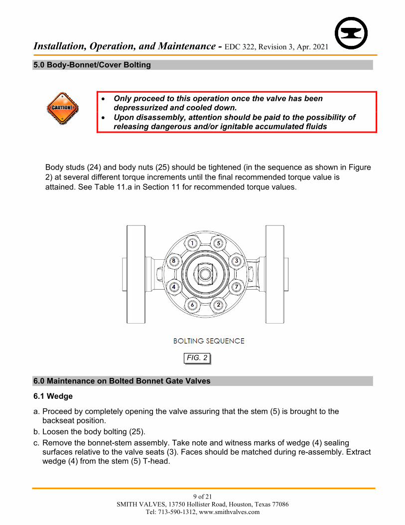
5.0 Body-Bonnet/Cover Bolting
• Only proceed to this operation once the valve has been depressurized and cooled down.
• Upon disassembly, attention should be paid to the possibility of releasing dangerous and/or ignitable accumulated fluids
Body studs (24) and body nuts (25) should be tightened (in the sequence as shown in Figure 2) at several different torque increments until the final recommended torque value is attained. See Table 11.a in Section 11 for recommended torque values.
6.0 Maintenance on Bolted Bonnet Gate Valves
6.1 Wedge
a. Proceed by completely opening the valve assuring that the stem (5) is brought to the backseat position.
b. Loosen the body bolting (25). c. Remove the bonnet-stem assembly. Take note and witness marks of wedge (4) sealing
surfaces relative to the valve seats (3). Faces should be matched during re-assembly. Extract wedge (4) from the stem (5) T-head.
FIG. 2

Installation, Operation, and Maintenance - EDC 322, Revision 3, Apr. 2021
10 of 21
SMITH VALVES, 13750 Hollister Road, Houston, Texas 77086 Tel: 713-590-1312, www.smithvalves.com
RIGHT POSITION WRONG POSITION
d. Do a visual check of all sealing surfaces to ensure that there are no incisions or marks. e. If there are any, use fine sandpaper or emery cloth to eliminate them, assuring that the
original planarity of these surfaces is not modified. f. Replace with a new gasket (6) between body (1) and bonnet (2), insert wedge (4) in the stem
T-head making sure that the faces are matched as noted above. g. Bring the bonnet assembly to its original position and tighten the body bolts (25) as described
in Section 5.
6.2 Stem
a. Proceed by completely opening the valve, assuring that the stem (5) is brought to the backseat position.
b. Loosen the body bolting (25). c. Remove the bonnet assembly. Take note and witness marks of wedge (4) sealing surfaces
relative to the valve seats (3) (refer to Figure 3). Faces should be matched during re-assembly. Extract wedge (4) from the stem T-head.
d. Disassemble the stem assembly by turning the handwheel (16) in the clockwise direction. e. Make sure that the stem (5) surface in contact with the packing (8) is not damaged. If the
stem (5) is damaged beyond repair, call for a stem replacement or consider replacing the entire valve.
f. Replace the stem (5) by inserting it through the bonnet (2) until the stem (5) comes in contact with the yoke nut (14).
g. Turn the handwheel (16) in the counterclockwise direction to retract the stem (5) until it touches the back seat.
h. Replace with a new gasket (6) between the body (1) and bonnet (2). Insert the wedge (4) onto the stem (5) T-head making sure that the faces are matched as noted above.
i. Bring the bonnet assembly to its original position and tighten the body bolts (25) as described in Section 5.
FIG. 3

Installation, Operation, and Maintenance - EDC 322, Revision 3, Apr. 2021
11 of 21
SMITH VALVES, 13750 Hollister Road, Houston, Texas 77086 Tel: 713-590-1312, www.smithvalves.com
6.3 Seats
No repairs are possible on seats (3) of gate valves. Replacement of seat is possible, provided the right tools are available.
Blunt chisels and a hammer can be used to remove the old seats (3) after removal of the bonnet assembly. New seats (3) must be assembled by expanding the ends. We recommend that this process be carried out only in our factory where proper tooling is available or call us for a replacement valve.
7.0 Maintenance on Bolted Bonnet Globe Valves
7.1 Disc and Seat
The body seating surface is integral. To check the seal characteristics between the disc and body seating area, we suggest the “BLUING TEST”: a. Proceed by completely opening the valve, assuring that the stem is brought to the
backseat position. b. Loosen the body bolting (25). c. Remove the bonnet assembly. d. Ensure seat and disc (4) surfaces are clean and free of dirt and debris. e. Apply some Prussian-Blue on the disc (4). f. Place the bonnet assembly in the original position, and hand tighten the body bolts (25). g. Bring the valve to the closed position, wait 20 seconds, and repeat steps “a”, “b” and “c”
above. h. Check that the blue trace on the disc (4) and the body (1) is uniformly present on the
contact surfaces. If this has not occurred there are two possibilities: • There are incisions or marks on sealing surfaces, either the disc (4) or the body (1).
Check and, if any, use fine sand paper or emery cloth to eliminate them, taking care that the original planarity of these surfaces is not modified.
• If light or moderate scratches or incisions are witnessed, we recommend lapping the disc (4) directly to the body seat. See Appendix A.
i. Replace with a new body gasket (6). j. Reassemble the bonnet assembly and tighten body bolts (25) as described in Section 5.0
7.2 Stem Assembly
a. Proceed by completely opening the valve, assuring that the stem (5) is brought to the backseat position.
b. Loosen the body bolting (25).
Installation, Operation, and Maintenance - EDC 322, Revision 3, Apr. 2021
12 of 21
SMITH VALVES, 13750 Hollister Road, Houston, Texas 77086 Tel: 713-590-1312, www.smithvalves.com
c. Remove the bonnet assembly. d. Disassemble the stem assembly by holding the stem (5) and turning the handwheel (16)
in the clockwise direction. e. Make sure that the stem surfaces in contact with the packing (8) are not damaged. If the
stem assembly is damaged beyond repair, contact our sales department for a new stem assembly (which includes the stem (5), disc (4), and disc wire (13)) or consider replacing the entire valve.
f. Reinstall stem keys (30) onto the stem (5). g. Install the stem assembly by inserting it through the bonnet (2), packing (8), and gland
flange (10) until the stem assembly comes in contact with the yoke nut (14). h. Turn the handwheel (16) in the counter-clockwise direction to retract the stem (5) until it
touches the back seat. i. Replace with a new gasket (6) between body (1) and bonnet (2) and place the bonnet
assembly onto the body (1). j. Bring the bonnet assembly to its original position and tighten the body bolts (25) as
described in Section 5.0 8.0 Maintenance on Bolted Cap Check Valves
There are two types of check valves: ball and piston.
8.1 Ball, Piston and Their Seats
a. Seats are integral to the body (1). b. Loosen the body bolting (25). c. Remove all parts, taking note of the order of disassembly. d. Do a visual check of all sealing surfaces. e. No incisions or marks shall be on the sealing surfaces. f. If there are any on the piston/ball (4) or the body (1), use emery cloth to eliminate them,
assuring that the original planarity of the surface is not modified. g. If there are any incisions or marks on the piston/ball (4), or the above step is not
successful, contact our sales department to purchase a new ball (4), piston (4), or a replacement valve.
h. Replace with a new body gasket (6). i. Reassemble the valve in the reverse order of the disassembly and tighten the body bolts
(25) as described in Section 5.0

Installation, Operation, and Maintenance - EDC 322, Revision 3, Apr. 2021
13 of 21
SMITH VALVES, 13750 Hollister Road, Houston, Texas 77086 Tel: 713-590-1312, www.smithvalves.com
9.0 PWHT (Post Weld Heat Treatment)
9.1 PWHT Responsibility
Smith is responsible for all valve fabrication PWHT during manufacture of valve.
The end user is responsible for any PWHT required after welding the valve in line.
9.2 PWHT Requirements/Recommendations
PWHT shall be performed in accordance with the appropriate user’s WPS-PQR instructions. Do not wrap the entire valve body with heating element. All heating shall be performed with localized heating equipment to minimize adverse effects to the rest of the valve. The heat band shall be extended to include the weld HAZ (heat affected zone) of the joints. The gate valve to undergo PWHT shall be in slight open position, approximately opened 1/16 turn from completely closed position. This will allow material expansion and help hold the gate valve seats in place.
Globe, Piston and Ball check valves have integral body seat and so PWHT would not affect the seat becoming loose.
We recommend allowing the part to cool down after each weld pass to avoid excessive heat build-up. Allow the heated valve assembly to cool before actuating it. Make sure that no adverse effect has taken place during heating and the valve can be cycled open-closed for proper operation. In the absence of a governing specification, the requirements of ASME B31.1 or B31.3 for PWHT shall be considered.
For NACE valves, a NACE qualified user’s WPS shall be used.
Valves with PTFE packing and gasket which have temperature limitations lower than the valve base material, may require special heat treatment procedures to be followed based on end-user requirements.
Installation, Operation, and Maintenance - EDC 322, Revision 3, Apr. 2021
14 of 21
SMITH VALVES, 13750 Hollister Road, Houston, Texas 77086 Tel: 713-590-1312, www.smithvalves.com
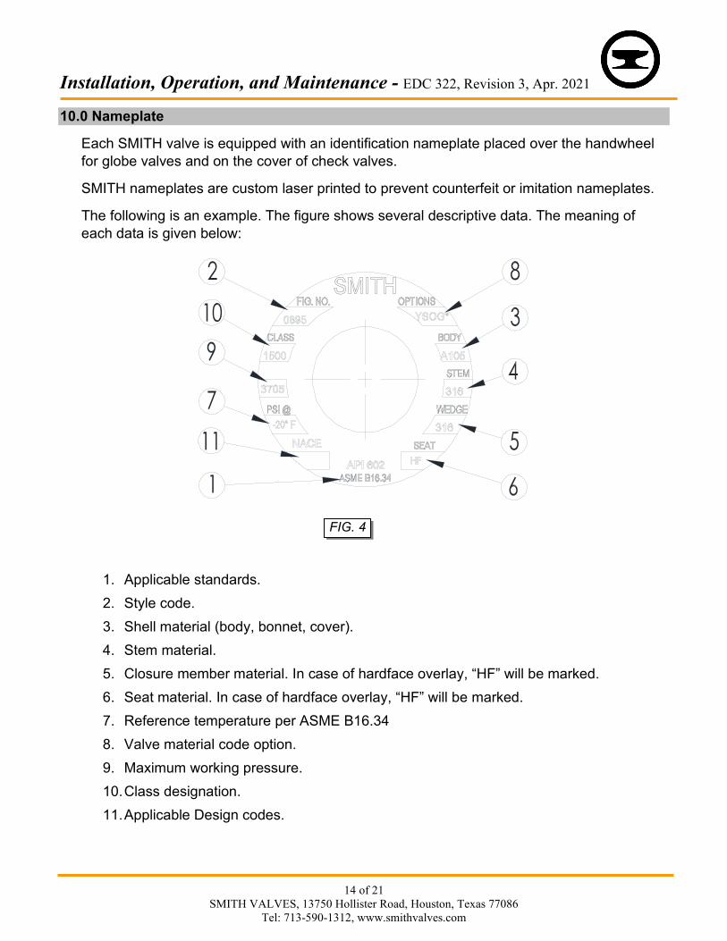
10.0 Nameplate
Each SMITH valve is equipped with an identification nameplate placed over the handwheel for globe valves and on the cover of check valves.
SMITH nameplates are custom laser printed to prevent counterfeit or imitation nameplates.
The following is an example. The figure shows several descriptive data. The meaning of each data is given below:
1. Applicable standards.2. Style code. 3. Shell material (body, bonnet, cover). 4. Stem material. 5. Closure member material. In case of hardface overlay, “HF” will be marked. 6. Seat material. In case of hardface overlay, “HF” will be marked. 7. Reference temperature per ASME B16.34 8. Valve material code option. 9. Maximum working pressure. 10. Class designation. 11. Applicable Design codes.
FIG. 4
Installation, Operation, and Maintenance - EDC 322, Revision 3, Apr. 2021
15 of 21
SMITH VALVES, 13750 Hollister Road, Houston, Texas 77086 Tel: 713-590-1312, www.smithvalves.com
11.0 Tables
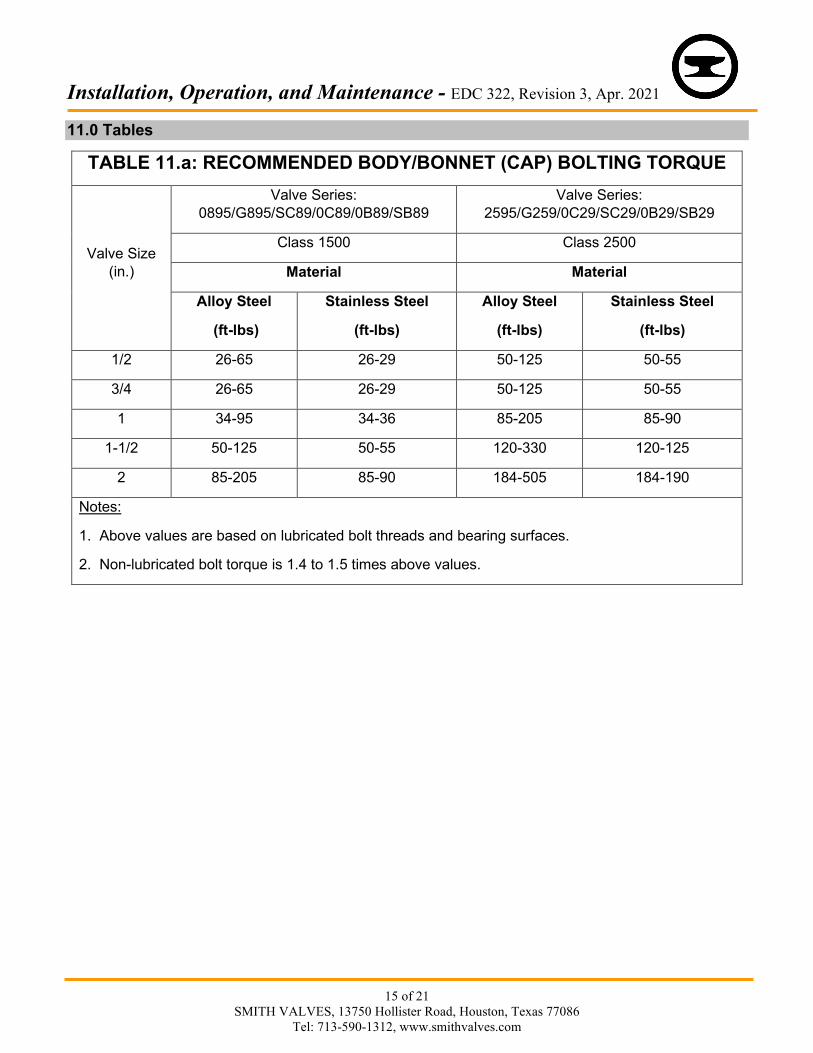
TABLE 11.a: RECOMMENDED BODY/BONNET (CAP) BOLTING TORQUE
Valve Size (in.)
Valve Series: 0895/G895/SC89/0C89/0B89/SB89
Valve Series: 2595/G259/0C29/SC29/0B29/SB29
Class 1500 Class 2500
Material Material
Alloy Steel
(ft-lbs)
Stainless Steel
(ft-lbs)
Alloy Steel
(ft-lbs)
Stainless Steel
(ft-lbs)
1/2 26-65 26-29 50-125 50-55
3/4 26-65 26-29 50-125 50-55
1 34-95 34-36 85-205 85-90
1-1/2 50-125 50-55 120-330 120-125
2 85-205 85-90 184-505 184-190
Notes:
1. Above values are based on lubricated bolt threads and bearing surfaces.
2. Non-lubricated bolt torque is 1.4 to 1.5 times above values.
Installation, Operation, and Maintenance - EDC 322, Revision 3, Apr. 2021
16 of 21
SMITH VALVES, 13750 Hollister Road, Houston, Texas 77086 Tel: 713-590-1312, www.smithvalves.com
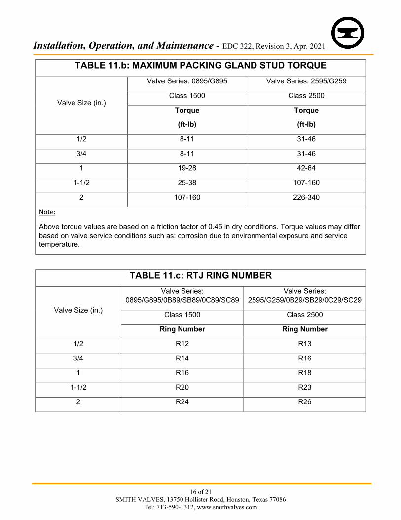
TABLE 11.b: MAXIMUM PACKING GLAND STUD TORQUE
Valve Size (in.)
Valve Series: 0895/G895 Valve Series: 2595/G259
Class 1500 Class 2500
Torque
(ft-lb)
Torque
(ft-lb)
1/2 8-11 31-46
3/4 8-11 31-46
1 19-28 42-64
1-1/2 25-38 107-160
2 107-160 226-340
Note:
Above torque values are based on a friction factor of 0.45 in dry conditions. Torque values may differ based on valve service conditions such as: corrosion due to environmental exposure and service temperature.
TABLE 11.c: RTJ RING NUMBER
Valve Size (in.)
Valve Series: 0895/G895/0B89/SB89/0C89/SC89
Valve Series: 2595/G259/0B29/SB29/0C29/SC29
Class 1500 Class 2500
Ring Number Ring Number
1/2 R12 R13
3/4 R14 R16
1 R16 R18
1-1/2 R20 R23
2 R24 R26
Installation, Operation, and Maintenance - EDC 322, Revision 3, Apr. 2021
17 of 21
SMITH VALVES, 13750 Hollister Road, Houston, Texas 77086 Tel: 713-590-1312, www.smithvalves.com
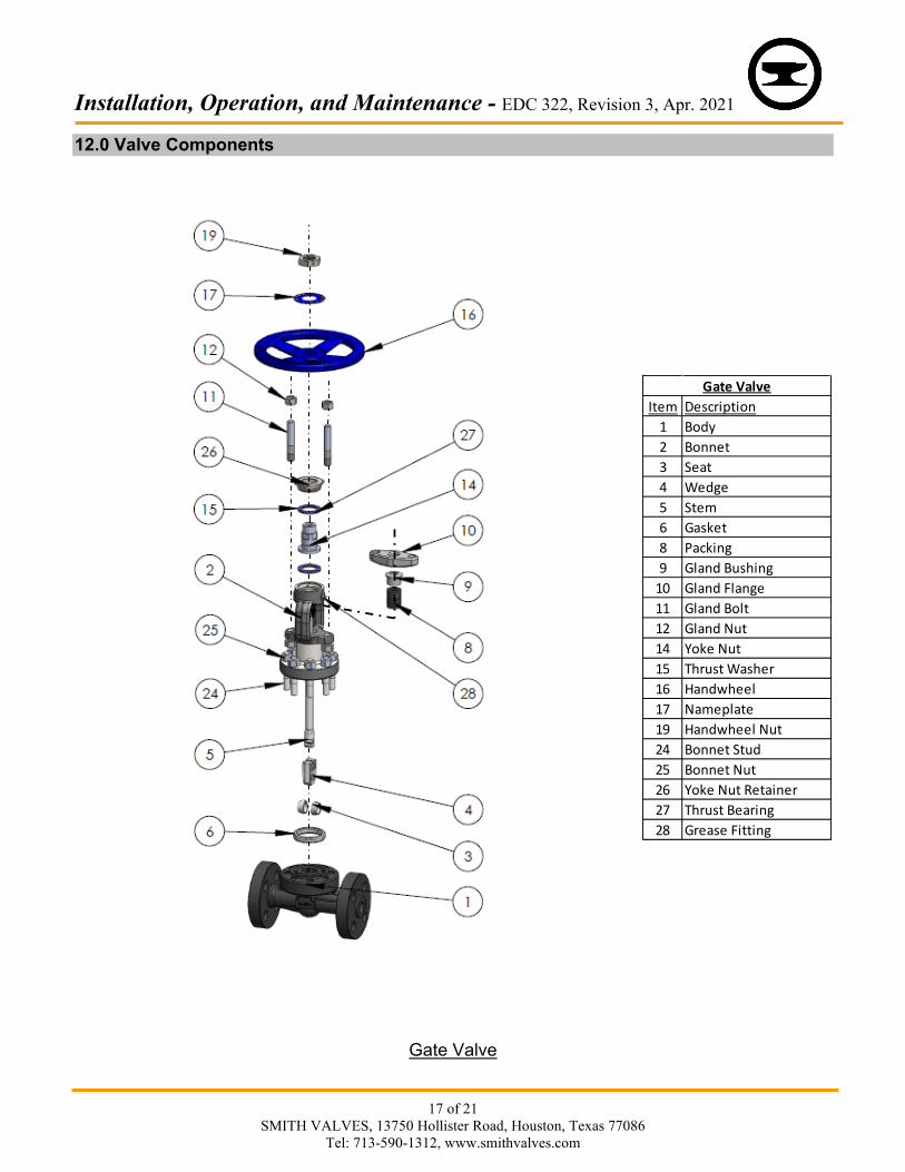
12.0 Valve Components
Gate Valve
Item Description1 Body2 Bonnet3 Seat4 Wedge5 Stem6 Gasket8 Packing9 Gland Bushing
10 Gland Flange11 Gland Bolt12 Gland Nut14 Yoke Nut15 Thrust Washer16 Handwheel17 Nameplate19 Handwheel Nut24 Bonnet Stud25 Bonnet Nut26 Yoke Nut Retainer27 Thrust Bearing28 Grease Fitting
Gate Valve

Installation, Operation, and Maintenance - EDC 322, Revision 3, Apr. 2021
18 of 21
SMITH VALVES, 13750 Hollister Road, Houston, Texas 77086 Tel: 713-590-1312, www.smithvalves.com
Globe Valve
Item Description1 Body2 Bonnet4 Disc (Note1)
5 Stem (Note 1)
6 Gasket8 Packing9 Gland Bushing
10 Gland Flange11 Gland Bolt12 Gland Nut13 Disc Wire (Note 1)
14 Yoke Nut15 Thrust Washer16 Handwheel17 Nameplate19 Handwheel Nut24 Bonnet Stud25 Bonnet Nut26 Yoke Nut Retainer27 Thrust Bearing28 Grease Fitting30 Stem Key
Globe Valve

Installation, Operation, and Maintenance - EDC 322, Revision 3, Apr. 2021
19 of 21
SMITH VALVES, 13750 Hollister Road, Houston, Texas 77086 Tel: 713-590-1312, www.smithvalves.com
Note (1): Replacement of stem would require replacement of entire stem assembly which includes: stem (5), disc (4), and disc wire (13).
Piston Check Valve
Item Description1 Body2 Cap4 Piston6 Gasket17 Nameplate22 Spring24 Cap Stud25 Cap Stud Nut29 Disc Guide
Piston Check Valve

Installation, Operation, and Maintenance - EDC 322, Revision 3, Apr. 2021
20 of 21
SMITH VALVES, 13750 Hollister Road, Houston, Texas 77086 Tel: 713-590-1312, www.smithvalves.com
Ball Check Valve
Item Description1 Body2 Cap4 Ball6 Gasket17 Nameplate22 Spring24 Cap Stud25 Cap Stud Nut29 Disc Guide
Ball Check Valve
Installation, Operation, and Maintenance - EDC 322, Revision 3, Apr. 2021
21 of 21
SMITH VALVES, 13750 Hollister Road, Houston, Texas 77086 Tel: 713-590-1312, www.smithvalves.com
13.0 List of Appendices
APPENDIX A Lapping Procedure for Globe and Check Valves Valves can leak due to scratches and imperfections on the valve disc. Lapping is a procedure that is used to remove these imperfections from the disc and stop leakage. The lapping procedures are as follows: a. Remove the stem assembly from the bonnet (2) as described in Section 7.2, steps “a”
through “d”. b. Use two 8-32 UNC set screws to tighten the disc (4) and prevent from spinning. Ensure that
the set screws are tightened evenly. c. Select the type of lapping compound to use. d. Apply a small amount of lapping compound to the disc (4). e. Begin lapping by inserting the stem assembly into the body (1).
Ensure that the stem assembly is placed in the center of the seat and not at an angle.
f. Apply a circular oscillating motion to the stem assembly. This can be done by hand or by placing the stem assembly in a drill. If a drill is used, use the lowest setting on the drill. Continue the circular motion for approximately two minutes. Ensure that the stem is in a straight/vertical position while applying the circular motion.
g. Remove the stem assembly from the body (1) by pulling straight up. Avoid removing it horizontally or “turning” it off at an angle.
h. Clean the disc (4) and seat surface using an approved cleaner/degreaser. Blow-dry the components or allow to air dry.
i. Inspect the surface of the disc (4) and determine if another lapping session is needed. j. If another session is needed, repeat steps “d” through “h” one or two more times. k. No further lapping sessions are needed once the disc is free of imperfections and has a
mirror-like finish. l. It is recommended that a Bluing Test is performed. Refer to Section 7.1, steps “d” through
“h”. m. Reassemble the valve as described in Section in 7.2, steps “f” through “j”, and test the valve
to ensure there are no leaks.