Embed Size (px)
DESCRIPTION
flange report
Citation preview

t
.OAK RIDGE NATIONAL LABORATORY LIBRARY ORNL/Sub/2913-3
(NRC-5)P.R. 115-7b
3 M45b ODIATVO E
EVALUATION OF THE BOLTING AND FLANGES
OF ANSI B16.5 FLANGED JOINTS —
ASME PART A DESIGN RULES
E. C. RodabaughS. E. Moore
Work funded by the Nuclear Regulatory CommissionUnder Interagency Agreement 40-495-75
September 30, 1976
<V
OAK RIDGE NATIONAL LABORATORY
CENTRAL RESEARCH LIBRARYCIRCULATION SECTION
4500N ROOM 175
LIBRARY LOAN COPYDO NOT TRANSFER TO ANOTHER PERSON.
if you wish someone else to see this report, send inname with report and the library will arrange a loan.
ORNL-118 (6-97)
Work Performed by
BATTELLE
Columbus Laboratories
505 King AvenueColumbus, Ohio 43201
for
OAK RIDGE NATIONAL LABORATORY
Oak Ridge, Tennessee 37830operated by
UNION CARBIDE CORPORATION
for the
ENERGY RESEARCH AND DEVELOPMENT ADMINISTRATION
Contract No. W-7405-26

Printed in the United States of America
Available from
National Technical Information Service
U. S. Department of Commerce
5285 Port Royal RoadSpringfield, Virginia 22151
Price: Printed Copy $7.50; Microfiche $2.25
This report was prepared as an account of work sponsored by theUnited States Government. Neither the United States nor the Energy Research and Development Administration, nor the Nuclear RegulatoryCommission, nor any of their employees, nor any of their contractors,subcontractors, or their employees, makes any warranty, express or implied, or assumes any legal liability or responsibility for the accuracy,completeness of usefulness of any information, apparatus, product orprocess disclosed, or represents that its use would not infringe privatelyowned rights.
EVALUATION OF THE BOLTING AND FLANGES
OF ANSI B16.5 FLANGED JOINTS
ASME PART A DESIGN RULES
by
, C. Rodabaughand
S. E. Moore
Manuscript Completed: August 20, 1976Date Published: September, 1976
ORNL/Sub/2913-3NRC-5
P.R. 115-7b
NOTICE This document contains information of a preliminarynature and was prepared primarily for internal use at theOak Ridge National Laboratory. It is subject to revisionor correction and therefore does not represent a final report
OAK RIDGE NATIONAL LABORATORY LIBRARY
3 i4M5b 0Q1AT70 2

11
TABLE OF CONTENTS
Page
FOREWORD iv
1. INTRODUCTION 1
Nomenclature 3
2. CODE REQUIREMENTS FOR FLANGED JOINTS 7
3. SPECIFIC FLANGED JOINT CALCULATIONS 11
Classes, Sizes, Types H
Pressure-Temperature Ratings 12
Dimensions 12
4. BOLT AREAS AND BOLT STRESSES 14
Required Bolt Areas Per NB-3647.1(b) 14
Bolting Requirements of NB-3230 18
NB-3232.1 Average Stress 18
NB-3732.2 Maximum Stress 30
NB-3232.3 Fatigue Analysis of Bolts 37
Summary of Results on Bolt Areas and Bolt Stresses 40
5. FLANGE STRESSES 41
Flange Stress Limits of NB-3647 41
Stresses of Rated Pressures, Zero Pipe Bending Moment. ... 42
Allowable Pressures, Zero Pipe Bending Moment 48
Allowable Pipe Bending Stresses at Rated Pressure ... 51
Basic Theory Flange Stresses 52
Flange Stresses at Preload Bolt Stress of 40,000 psi. . 54

iii
TABLE OF CONTENTS (Continued)
Page
Stresses at Preload (S = 40,000)Plus Operating Conditions 63
Effect of Pipe Bending Moment onFlange Stresses 72
Summary of Results on Flange Stresses 74
6. RECOMMENDATIONS 76
7. ACKNOWLEDGEMENT 90
8. REFERENCES 91
APPENDIX A, "TEST DATA ON FLANGED JOINTS"
APPENDIX B, "DEVELOPMENT OF SIMPLE EQUATIONS FOR LIMITATION OFPIPE BENDING AND TORSIONAL MOMENTS
APPENDIX C, "RECOMMENDED CODE REVISIONS"

IV
FOREWORD
The work reported here was performed at the Oak Ridge National Laboratory
and at Battelle-Columbus Laboratories under Union Carbide Corporation, NuclearDivision, Subcontract No. 2913 in support of the ORNL Design Criteria for Piping andNozzles Program. This program is sponsored by the Division of Reactor SafetyResearch, Office of Nuclear Regulatory Research, U. S. Nuclear RegulatoryCommission; E. K. Lynn of the Metallurgy and Materials Branch is the cognizantRSR engineer, and S. E. Moore, Reactor Division, ORNL, is the program manager.
Activities under the Design-Criteria program are coordinated with
other safety-related piping and pressure-vessel research through the DesignDivision of the Pressure Vessel Research Committee (PVRC) of the Welding ResearchCouncil and through the ASME Boiler and Pressure Vessel Code Committee as part
of a cooperative effort with industry to confirm and/or improve the adequacyof design criteria and analytical methods used to assure the safe design of
nuclear power plants.
The study of ANSI B16.5 flanged piping joints, conducted using the
ASME Part-A design rules described in this report, is a portion of a three-part study of flanged joints for the evaluation of design rules in current codesand standards. Results from these studies will be used by appropriate ASME Code
groups in drafting new and improved design rules.
Other reports in this series are:
1. E. C. Rodabaugh, F. M. O'Hara, Jr., and S. E. Moore, FLANGE: A Computer
Program for the Analysis of Flanged Joints with Ring-Type Gaskets,
ORNL-5055 (January, 1976).
2. E. C. Rodabaugh and S. E. Moore, Flanged Joints with Contact Outsidethe Bolt Circle — ASME Part B Design Rules, ORNL/Sub/2913, Report No. 1
(May, 1976).

1. INTRODUCTION
The bolted flanged joint represents perhaps the most compli-(1)*
cated structure for which specific design rules are given in the Code
For most structures (pressure boundaries) covered by the Code, the stress
is proportional to the pressure, and "failure" occurs when the pressure
boundary is penetrated by a crack. For flanged joints, however, the
major stresses occur due to tightening the bolts and, in general, are
changed only slightly by pressure. The criterion defining failure is
usually excessive leakage at the gasket. Such leakage can often by stopped
by additional tightening of the bolts; i.e., the problem is solved by imposing
still higher stresses on the bolts and flanges.
Perhaps because of the unusual characteristics of a flanged
joint, the basic philosophy of the Code, in which maximum stress limits
are imposed, is somewhat difficult to intrepret when applied to a
bolted flanged joint. This is particularly true for piping where ANSI B16.5
flanges are ordinarily used.
A review of the NB-3600 rules for Class 1 piping design, as they ex
isted in the 1971 edition of the Code, was made in 1972 by one of the authors.
At that time, several major problems in the Code rules were pointed out con
cerning flanged joints. One of these involved subarticles NC-3600 and ND-3600
which, by reference to NB-3647, in effect, required a fatigue analysis of the
bolting of flanged joints in Class 2 and 3 piping. This has been corrected
by copying the text of NB-3647 into NC-3647 and into ND-3647, but leaving
out the sentence "These minimum bolt areas may have to be increased to meet
requirements of NB-3230." Another problem involved the use of the equation con
tained in NB-3647.1(a) for calculating the equivalent pressure, P . It waseq
noted that using P for checking the capacity of B16.5 flanged joints for pipe
bending-moment capacity would give very low allowable moments. It was recom
mended, as a partial solution, that P rather than P be used in calculatingeq
H . This was incorporated into the Code as Case 1677.P
* Code, in this report, refers specifically to the ASME Boiler andPressure Vessel Code, Section III, Nuclear Power Plant Components,Reference (1).
At the present time, a number of ambiguities and unnecesary re
strictions on the use of B16.5 flanged joints in the Code rules still
remain. This report was prepared to investigate the use of B16.5 flanged
joints in Code Applications and to make recommendations for appropriate modi
fications of the Code rules. Toward this end, calculations were made for
a representative sampling of B16.5 flanges as described in Chapter 3,
Specific Flanged Joint Calculations".
Calculations were made using the Code procedures and also with
the more basic theoretical analysis of Reference (3), and the computer
program FLANGE which was developed to implement that analysis.
Both the Code procedures and the theoretical analysis of Reference
(3) are based on simplified analytical methods. Available test data on
flanged joints are presented and compared with results from FLANGE calculations
in Appendix A. These comparisons indicate that the calculation methods used
in the text of the report are conservative, but not necessarily accurate.
One objective of this report is to develop relatively simple
but conservative methods of evaluating the adequacy of piping products
used in Code Class-1, Class-2, and Class-3 piping systems. The rather
extensive and detailed evaluations of ANSI B16.5 flanged joints contained
in the text of this report provide the basis for the development of re
latively simple equations for ANSI B16.5 flanged joints developed in
Appendix B. These simple equations from Appendix B are then included in
Appendix C in the form of recommended revisions to the Code.

Nomenclature
A^ = Bolt cross sectional area (all bolts)
A, = Bolt cross sectional area of a single bolt
A =m
Design bolt area = larger of W ,/S, or W „/S , Codej c. .^. mlb m2 adefinition
*
a1 , a„, a , a, = Bolt change factors, see Eq. (9) and Tables 5 and 6.
B = Flange inside diameter
b = Effective gasket seating width, Code definition
C = Bolt circle diameter
D = Pipe outside diametero
D = Mean (midwall) pipe diameter
d = Bolt diameter
E = Modulus of elasticity
E1 = Modulus of elasticity at bolt preload temperature
E = Modulus of elasticity at operating temperatures
F = Axial force in attached pipe (see Table 1)
F, = Axial force in boltb
G = Effective gasket diameter, Code definition
* For users of the computer program FLANGE:
ax = (Wl-W2B)/Ab for P = P = P
a = (Wl-W2C)Ab for P = P
a = (Wl-W2A)/Ab for (Tb ~ Tf) = 50 F
a4 = (Wl-W2D)/Ab for (Th - Tf) = 100 F
Nomenclature (Continued)
G = Gasket outside diametero
G. = Gasket inside diameter1
G = Gasket mean diameter = (G + G.)/2
G = Effective gasket diameter
g = Attached pipe wall thickness, welding neck flanges
H 2b irGmP, Code definitionP
h = Tapered hub length, welding neck flanges
h-, = (C - G )/2, where G = G, G or G as indicated in textk me
I = Effective bolt length, taken herein as 2t + d + 1/8"
M = The symbol M for pipe moment is used only in Table 1,P taken from the Code. Elsewhere, it is identified as
M , . This is to distinguish it from the moments
applied by couples to flange (e.g., bolt-load/gasketreaction couple).
M = Moment applied by couples to flange e.g., bolt load/gasket reaction couple).
M = Total moment acting upon flange, Code definition
M = Total moment acting upon flange, gasket seating conditions,Code definition
m = Gasket factor, Code definition
N = Design cyclic life as obtained by Code procedure
P = Internal pressure
P = Primary rating pressure per ANSI B16.5 (equal toclass designation)
Pea = Pressure equivalent of pipe bending moment, NB-3647 definition,H = 16 M ^G3
pbt
ppn = Pressure equivalent of pipe bending moment as used in FLANGE =q 4S jg /D
pb o o
PT = Leakage pressure

Nomenclature (Continued)
pb> Q = Stress categories, Code definitions
S = Stress
S ,, = Allowable flange stress
sa = Allowable bolt stress at atmospheric temperature,Code definition
sb = Allowable bolt stress at design temperature, Codedefinition
S, , = Bending stress in bolts
S,, = Initial or preload bolt stress
S, „ = Bolt stress after application of loads
S, = Critical bolt stressbe
S, = Shear bolt stressbs
S ,S ,S = Flange stresses, Code definitionH K 1
S = Allowable stress intensity, Code definition, Class 1components
S , = Maximum stress in attached pipe due to moment, M .PD pb
S = Range of primary-plus-secondary stress
S = Range of primary-plus-secondary-plus-peak stress
S^ = Stress intensity in a bolt, including bending stresst
Sa = Stress amplitude (Used in conjunction with Codefatigue curves)
T = Torque applied in tightening bolts
T = Temperature of bolts
T = Temperature of flange ring
T = Temperature of flange hub and pipe
t = Flange ring thickness and blind flange thickness
W = Total bolt load
W = Design bolt load, operating conditions, Codedefinition

m2
Nomenclature (Continued)
Design bolt load, gasket seating conditions,Code definition
y - Gasket seating load, Code definition
0 = Rotation in radians
Q-^ = Rotation of flange ring of one flange in joint
02 = Rotation of flange ring of other flange in joint
Rotation of flange ring due to moment
Rotation of flange ring due to pressure
0m
0P
©„ Rotation of flange ring due to thermal gradient(ThP - V
2. CODE REQUIREMENTS FOR FLANGED JOINTS
In the Code, NB-3640 (Pressure Design) requires that the product
satisfy the stated criteria for the design pressure at the design temperature.
Under NB-3650, the product must satisfy the stated criteria for all loads;
i.e., pressures, moments and thermal gradients. The rules for flanged joints
in the Code do not conform to this basic organization; one of the objectives
of the recommendations of this report is to provide rules under NB-3640 and
NB-3650 that parallel those for all other products.
NB-3640 contains two paragraphs which are relevant to the
subject of B16.5 flanged joints: These are NB-3647 and NB-3649. NB-3649
states that:
"Other piping products manufactured in accordance with
the standards listed in Table NB-3691-1 shall be
considered suitable for use provided the design is
consistent with the design philosophy of this subsection."
There are three significant points with respect to the above quote.
(1) ANSI B16.5 is included in Table NB-3691-1.
(2) "This subsection", by Code definition, is the entire
NB-portion of the Code.
(3) NB-3612.1 provides an additional restriction in
stating that the pressure-temperature ratings of
the standards shall not be exceeded.
Accordingly, NB-3649 implies that B16.5 flanges meet the requirements
of NB-3640 (pressure design) provided the design pressure/temperature
is below the rated pressure/temperature combination given in B16.5.
However, it is not clear what is meant by "the design is consistent with
the design philosophy of this subsection".As written, the Code requires
that the design of B16.5 flanged joints be consistent with the NB subsection
design philosophy. A seemingly appropriate way to check for "consistency"

8
is to see if B16.5 flanged joints conform to the requirements of NB-3647,
"Pressure Design of Flanged Joints and Blanks"; in particular, NB-3647.1,
"Flanged Joints". NB-3647 is shown herein as Table 1. NB-3647.1(b)
gives methods to establish minimum bolt areas, but then states "These
minimum bolt areas may have to be increased to meet requirements of
NB-3230. NB-3230 is shown herein as Table 2.
A major portion of this report is directed towards the
evaluation of B16.5 flanged joints and their pressure-temperature
ratings to see if they are consistent with the requirements of NB-3647.1.
The detailed interpretation of the rules is covered in the text. At
this time, we only point out that:
(1) NB-3647.1 is a part of NB-3640 on Pressure Design,
yet it gives explicit rules for moments applied to
the flanged joint by the attached piping. Moment
loads, for all other products, are considered ex
plicitly only under NB-3650 on Analysis of Piping
Products.
(2) The moment to be used in NB-3647.1 apparently does not
include all of the significant sources of moment;
e.g., relief valve thrust, anchor movements or
misalignment that is "pulled-out" during make
up of the joint.
(3) The explicit inclusion of axial force loads in
NB-3647.1 is different from requirements for other
piping products. This type of load is not explicitly
considered for other piping products and, if con
sidered, would presumably be done under NB-3650.
(4) NB-3647 does not cover blind flanges.
The Code requirements for what is needed to show that a
B16.5 flanged joint meets NB-3650 appear to be quite clear. First,

TABLE 1, NB-3647 FROM ASME III
NB-3647 Pressure Design of Flanged Jointsand Blanks
NB-3647.1 Flanged Joints. This paragraph presentsanacceptable method forcalculating pressure stressesin flanged joints but should not be used for calculating maximum service stresses which are requiredto meet NB-3230. Thedesigner may usean alternativeprocedure provided that it includes the modificationsof this paragraph for the loads and stress limits forClass 2 piping. Flanged joints shall be analyzed andthe stresses evaluated by using the methods given inAppendix XI. revised in accordance with (a) through(d) below.
(a) The design pressure used for the calculation ofloads in a flanged joint by the equations in Xl-3220and Xl-3230, shall be replaced by a flange designpressure. PFD = P + P,r where P is the designpressure as defined in NB-3112.1 and Peq is anequivalent pressure to account for the moments andforces acting on the flanged joint due to weight andthermal expansion of the piping. The equivalentpressure, Peq shall be determined by the equation
eq
16A/ +_4FttG3 ttG2
where:
M= bending moment applied to the joint due toweight and thermal expansion of the piping,in. lb
F= axial force applied to the joint due to weightand thermal expansion of the piping, in. lb
C= diameter at location of effective gasket loadreaction as defined in XI-3130, in.
(b) Equations (3) and (4) in XI-3220 shall be usedto establish minimum bolt area required usingallowable stress values equal to Sm asgiven inTable I-1.3. These minimum bolt areas may have to beincreased to meet requirements ofNB-3230.
(c) Equation (6) in XI-3240 for longitudinal hubstress shall be revised to include the primary axialmembrane stress as follows
where:
_ _ /M0 ^PBSff - —— + —
Lg^B 4g0
P= design pressure as defined in NB-3112.1, psi.Other terms are defined in XI-3130.
(d) The allowable stress limits shall be
S/f not greater than 1.5 SmSRnot greater than 1.5Sm andSTnot greater than 1.5Sm

TABLE 2.
NB-3230 STRESS LIMITS FOR BOLTS
NB-3231 Design Conditions
(a) The number and cross sectional area of boltsrequired to resist the design pressure shall bedetermined in accordance with the procedures ofAppendix E, using the larger of the bolt loads given bythe equations of Appendix E as a design mechanicalload. The allowable bolt design stresses shall be thevalues given inTable1-1.3, for bolting materials.
(b) When sealing is effected by a seal weld insteadof a gasket, the gasket factor, m. and the minimumdesign seating stress, y, may be taken as zero.
(c) When gaskets are used for preservice testingonly, the design is satisfactory if the above requirements are satisfied for w= r = 0. and the requirements of NB-3232 are satisfied when theappropriate m and r factors are used for the testgasket.
NB-3232 Normal Conditions
Actual service stresses in bolts, such as thoseproduced by the combination of preload, pressure,and differential thermal expansion may be higherthan the values given in Table 1-1.3.
NB-3232.1 Average Stress. The maximum value ofservice stress, averaged across the bolt cross sectionand neglecting stress concentrations, shall notexceedtwo times the stress values of Table 1-1.3.
10
NB-3230 FROM ASME III
(b) High Strength Alloy Steel Bolting. High strengthalloy steel bolts and studs may be evaluated for cyclicoperation by the methods of NB-3222.4(e) using thedesign fatigue curve of Fig. 1-9.4 provided:
(1) The maximum value of the service stress(NB-3232.2) at the periphery of the bolt crosssectionresulting from direct tension plus bending andneglecting stress concentration shall not exceed 2.7Sm, if the higher ofthe two fatigue design curves givenin Fig. 1-9.4 is used. The 2 Sm limit for direct tension isunchanged.
(2) Threads shall be of a Vee-type -having aminimum thread root radius no smaller than 0.003 in.
(3) Fillet radii at the end of the shank shall besuch that the ratio of fillet radius to shank diameter isnot less than 0.060.
(c) Fatigue Strength Reduction Factor(NB-3213.17).Unless it can be shown by analysis or tests that alower value is appropriate, the fatigue strengthreduction factor used in the fatigue evaluation ofthreaded members shall notbe less than4.0. However,when applying the rules of NB-3232.3(b) for highstrength alloy steel bolts, the value used shall not beless than 4.0.
(d) Effect of Elastic Modulus. Multiply 5aU (asdetermined in NB-32I6.1 or NB-3216.2) by the ratioof the modulus of elasticity given on the design fatiguecurve to the value of the modulus ofelasticity used inthe analysis. Enter the applicable design fatigue curveat this value on the ordinate axis and find thecorresponding number of cycles on the axis ofabscissas. If the operational cycle being considered isthe only one which produces significant fluctuatingstresses, this is the allowable number ofcycles.
(e) Cumulative Damage. The bolts shall be acceptable for the specified cyclic application of loadsand thermal stresses provided the cumulative usagefactor, U, as determined in NB-3222.4(e)(5) does notexceed 1.0.
NB-3232.2 Maximum Stress. The maximum valueof service stress except as restricted by NB-3223.3, atthe periphery of the bolt cross section resulting fromdirect tension plus bending and neglecting stressconcentrations shall not exceed 3 times the stress
values of Table 1-1.3. Stress intensity, rather thanmaximum stress, shall be limited to this value whenthe bolts are tightened by methods other than heaters,stretchers, or other means which minimize residualtorsion.
NB-3233 Upset Conditions
The stress limits for Normal Conditions (NB-3232)apply.
NB-3234 Emergency Conditions
The stress limits of NB-3232.1 and NB-3232.2apply.
NB-3235 Faulted Conditions
If the Design Specifications specify anv FaultedConditions (NB-3113.4), the rules contained inAppendix F may be used in evaluating these FaultedConditions, independently of all other Design andOperating Conditions.
NB-3232.3 Fatigue Analysis of Bolts. Unless thecomponents on which they are installed meet all theconditions of NB-3222.4(d) and thus require nofatigue analysis, the suitability of bolts for cyclicoperation shall be determined inaccordance with theprocedures of (a) through (e)below.
(a) Bolting Having Less Than 100,000 psi TensileStrength. Bolts made of materials which have specified minimum tensile strengths of less than 100,000psi shall be evaluated for cyclic operation by themethods of NB-3222.4(e), using the applicable designfatigue curve of Fig. 1-9.4 and an appropriate fatiguestrength reduction factor (NB-3232.3(c)).
11
we note that stress indices for flanged joints (or flanges) are not
given in Table NB-3683.2-1. Accordingly, the flanged joint must
be analyzed according to the detailed requirements of NB-3200. The
analysis of the bolting is already covered by NB-3647.1 through its
reference to NB-3230. This leaves the flanges to be analyzed; this
aspect is discussed in this report in Chapter 5, "Flange Stresses".
3. SPECIFIC FLANGED JOINT CALCULATIONS
There are a large number of variables included in B16.5
flanges; i.e., pressure class, size, type, inside diameter (pipe
wall thickness for integral flanges), gasket dimensions and materials.
While a complete coverage of all these variables was not deemed
feasible, calculations for a fairly extensive sampling have been made,
and the results are presented herein. The sampling should be sufficient
to give the designer a good feel for important aspects of B16.5 flanged
joints and, with some restrictions, is deemed sufficient to provide the
equivalent of stress indices for such joints. The parameters covered
are listed below.
Classes, Sizes, Types
Pressure Class: all, i.e., 150, 300, 600, 900, 1500 and
2500 lb.
Sizes: 4", 8", 16" and 24" in all but the 2500 lb. For
2500 lb (maximum size covered is 12") the sizes are 4",
8", and 12".
Types:
(a) Welding neck flange joined to another welding neck
(b) Welding neck flange joined to straight hub flange
(c) Welding neck flange joined to a blind flange
* In principle, the Code user could develop stress indices or conductan experimental analysis.

12
Pressure-Temperature Ratings
The ratings given in the 1968 edition of B16.5 are used in
this report. The primary rating pressure, P, is:
P = class designation (psi) (1)
For example, P = 600 psi for the 600 class. The temperature at which Papplies depends upon the flange material. Ratings at other temperaturesare given in B16.5-1968.
Dimensions
Most dimensions of B16.5 flanged joints are given in B16.5;however, a few are not. These were selected as follows.
Inside Diameter (Wall Thickness): The wall thickness of the
pipe attached to the welding neck flange was established bythe equation:
PD
go = 2S2" + °'05 (2)where P = primary rating pressure, P (psi) is equal to the class
designation; e.g., P = 150 psi for the 150 lb classDQ = Pipe outside diameter
S = allowable stress, taken as 8750 psi. The value of S = 8750psi is approximately equal to the allowable stress of flangematerials at the primary rating temperature given in B16.5.
It is also the "representative allowable stress" used in
proportioning ratings in B16.5 to ASME Code allowable stresses.
The calculated value of gQ also establishes the flange inside diameterbore, B, and the hub thickness, g^ i.e., B=Dq -2go and g =(X -B)/2,where X=hub diameter at juncture with ring; X°is given in B16.5. Thetapered length of the hub was set equal to Y-C- 1.5g ,where Y-Ci<the total hub length; Y and C are given in B16.5.
LS

13
For straight hub flanges, the thickness g1 was assumed to
extend through the hub and pipe. This forms a reasonably good model
of a flange cast integrally into a valve or fitting body.
Gasket Dimensions: The gasket outside diameter is equal to the
raised face diameter (given in B16.5) and the inside diameter is
equal to the pipe outside diameter. Gasket thickness is 1/16".
Bolt Dimensions: The bolt areas are based on the root diameter of
the thread. Threads are Coarse-thread series in sizes 1" and
smaller; 8-pitch-thread series in sizes 1-1/8" and larger. Effective
bolt length is taken as 2t + d + 1/8", where t = flange ring thickness,
d = bolt diameter.
Calculations were made for bolt and flange stresses in*
accordance with Code procedures (Code Appendix XI) . These Code procedures
lead to minimum bolt areas and design loads which, in part, are
proportioned to the design pressure. The stresses due to the design
loads were then calculated. Calculations were also made using the more
basic theoretical analysis described in Reference (3). This analysis,
because it considers the flanges, bolts, and gasket as a statically
redundant structure, uses the modulus of elasticity of the materials
of the flanges, bolts, and gaskets. A modulus of 3 x 10 psi was
assumed for these materials.
The Code calculations require the use of m and y factors
which depend upon the gasket material. The values used in the cal
culations were m = 2.75, y = 3700; corresponding to the Code values
for 1/16" thick asbestos gasket material.
* Appendix XI does not cover blind flanges. The procedure of NC-3325and Figure NC-3325.1(e) was used for code calculations of stressesin blind flanges.
14
4. BOLT AREAS AND BOLT STRESSES
Required Bolt Areas Per NB-3647.1(b)
NB-3647.1(b) states that "Equations (3) and (4) in XI-3220
shall be used to establish minimum bolt area required using allowable
stress values equal to S as given in Table 1-1.3.m
Equations (3) and (4) of XI-3220 are:
For operating conditions:
Wml = (-7T/'4) c2p +2b7:GmP (3)For gasket seating:
W - (Am + V V2 (4)The required minimum bolt area, A , is the larger of W ,/S, or W ^/S ,
m ml b m2 a
where Wm2 = irbGy. The values given by equations (3) and (4) will,
of course, depend upon the gasket diameters and the Code m and y gasket
factors.
Table 3 shows values of W , and W „ for a commonly usedml m2 J
gasket. The required minimum bolt areas shown in Table 3 are based on
S = 35000 psi for SA-193 Code B7 bolt material at 100 F. The pressuresm r
are the rated pressures at 100 F. It can be seen that the actual bolt
areas are larger than the required minimum. Because the rated pressures
decrease more with increasing temperature than the decrease in the
allowable bolt stress with increasing temperature, it follows that the
bolt area is adequate for all temperatures.
Table 3 is for pressure loading only. When a bending moment
is imposed on the joint by the attached pipe, NB-3647.1(a) requires
that the design pressure be obtained by:
16 M ,p = p + P-2. e^FD „3 °;
* The direct axial force term is not included because its use is not
consistent with the present Code analysis of other piping products.
$
OfJ_
-H
WrJ
<
«o
«-Hooo
vOrH
vO
vO
vO
rH
00
o00
m
vO
St
00
CM
O
o00
m
CM
is
CM
mCO
CM
rH
VO
oorH
oCM
in
CM
CO
CO
rs
OorH
vO
on
CM
CM
00
ovO
00
OovO
oSt
00
CM
CO
Si-
ovO
CM
is
vO
O00
ON
St
CM
St
CM
00
00
orH
rH
CM
00
00
rH
CM
m00
rH
CO
CO
CO
VO
CO
CM
is
CO
00
00
CM
m
mCO
r-HCO
CO
m00
is-
oCM
00
vO
ON
CO
rH
rH
rH
00
CO
vO
OvO
00
ON
vO
rH0
00
0co
in
co
00
U0
st
CO
VO
Nis
Om
OH
CM
in
rHC
MIs
inrH
CO
oo
^-i
CM
NNOvO
CM
vO
rH
00
cm
mm
or-t
CO
oo
mon
st
mvo
cm
CO
CO
CM
VO
CM
st
is
rs
vo
mVO
r-i
is
l-H
mst
is
is
rH
co
rs
mcm
st
vo
on
co
co
cm
st
ON
rs
CO
OWN
(<1O
(^
ts
CI
O(Tiis
ro
Ow
is
en
OOn
is
co
om
nH
OO
rH
00
CM
st
00
CO
OO
rH
00
CM
st
00
CO
OO
rH
00
CM
st
00
CO
OO
rH
00
CM
st
00
CO
3O
rH
00
.•Nst
00
CO
OO
rH
00
CM
st
00
CO
OO
CM
CM
st
vO
CM
ON
OO
rs
CM
OO
CM
MO
O-ct
OO
OO
OO
OO
OO
OO
OO
^o
,e
oin
SrH
vO
Ct\C^
st
oCM
CM
CM
ojn
on
on
oON
00
CO
O00
vO
CM
OHNO
Ls
orH
CO
OO
co
a\
vo
st
mco
mCM
is
On
CM
00
T-\
ON
ON
CM
ON
ON
CM
OCO
CM
rH
r-{
r-t
CM
CM
mr-i
CO
rs
^-i
mo
i-HCM
IS
vO
rH
rH
st
CO
IS
rH
CM
co
oo
mrH
«-H
Pi
COP.
N•HCOCO
CD
mts
CM
st
00
VO
st
r-{CM
Oin
OCM
IS
st
00
vO
st
rH
CM
ooCO
OvO
ON
st
00
vO
st
r-i
CM
oost
Ost
st
st
00
vO
st
^CM
oovO
OvO
st
00
vO
st
rH
CM
ooON
OOvO
CO
st
00
vO
st
rH
CM
ooin
OOOvO
St
CO
CM
oo•n
CM
16
The question arises: what bending stress can be carried by the flanged
joint as limited by the bolting of B16.5 flanged joints? Noting that2
M , = S , Z , and using the approximation that Z = (ir/4) D g , Equatic
becomes:
*
Substituting P from Equation (6) for P in the first term of
Equation (3) and solving for S gives:
s Ko _ m b
Pb =(tt/4) G2 P + 2biTGmP
TTD g /G
(7)
Table 4 shows values of S calculated by Equation (7). The calculated
values of S are based on S = 26,700 psi for SA-193 Grade B7 boltpt> m
material at 700 F. Two sets of values for S , are shown in Table 4:pb
i
(1) S ,, with the attached pipe wall thickness obtained by
the equation: g = PD /17500+ 0.05. This gives a
pipe with about the same pressure rating as the flanges.
(2) S , with the attached pipe wall thickness equal to thepb _larger of std. wt. wall thickness or PD /17500 + 0.05.
This is significant, particularly for the 150 class,
because most piping is std. wt. or heavier wall
thickness.
Code Case 1677 states that in calculating H = 2biTGmP, the designpressure (not P™) shall be used.

17
TABLE 4. ALLOWABLE BENDING STRESS, S , or S , , IN PIPE ATTACHED TOpb pb
FLANGED JOINTS, P = RATED PRESSURE AT 700 F, NB-3647.1 RULES
BOLT STRESS CRITERIA
Class Size P, go
i
S ,(psi) forpb
S .(psi) for
psigo
larger of g orstd. wt. wall
150 4 110 .0886 36400 13600
8 .1239 16900 6500
16 .1871 22950 11450
24 .2557 23500 16100
300 4 470 .1271 26400 14200
8 .1979 14900 9100
16 .3243 22000 19000
24 .4614 17300 17300
400 4 635 .1529 31000 20000
8 .2471 15300 11700
16 .4157 20300 20300
24 .5986 19300 19300
600 4 940 .2043 16000 13800
8 .3457 12700 12700
16 .5986 14900 14900
•24 .8729 12900 12900
900 4 1410 .2814 24100 24100
8 .4936 15100 15100
16 .8729 9600 9600
24 1.2843 13900 13900
1500 4 2350 .4357 13800 13800
8 .7893 11500 11500
16 1.4214 15000 15000
24 2.1071 13650 13650
2500 4 3920 .6929 10550 10550
8 1.2821 10250 10250
12 1.8614 10400 10400

18
Pipe made of SA-106 Grade B material has an allowable stress intensity
S = 16,800 psi at 700 F. The limit on bending stress due to momentm
loads in straight pipe is given by Equation (12) of NB-3653.6 as
3 S = 50,400 psi. It can be seen in Table 4 that the calculatedm t-
(by NB-3647.1 rules) maximums of S for the flanged joints ranges
from 13 to 48 percent of that for straight pipe.
Bolting Requirements of NB-3230
NB-3647.1(b) states that the minimum bolt areas (as establi
shed by Equations (3) and (4) of XI-3220) "may have to be increased
to meet requirements of NB-3230". The contents of NB-3230 is included
herein as Table 2.
NB-3232.1 Average Stress
The maximum value of "service stress", averaged across the
bolt cross-section and neglecting stress concentrations, must not
exceed two times the tabulated allowable stress value. Service
stress is defined as stresses'feuch as those produced by the combina
tion of preload, pressure, and differential thermal expansion".
To examine the effect of this average stress limit on
B16.5 flanged joints, it is necessary to determine the magnitude
of preload used in tightening the bolts in B16.5 flanged joints.
The preload average bolt stress, S , should be such that when pressure,
differential thermal expansion, and pipe loads are applied to the
flanged joint in operation, the joint will not leak excessively.
It has been shown by Roberts that the theoretical
leakage pressure of a flanged joint with a non-pressure-sealing
gasket is given by the axial forces equilibrium equation:
* Leakage is defined as the gross type of leakage that occurs whenthe load on the gasket is reduced to zero. Slow, diffusion-typeleakage may and generally will occur at lower pressures.
** The types of gaskets covered by Equation (8) includes all ofthose shown in Table XI-3221.1, except the "ring joint". The"ring joint" may have some pressure-sealing capability. Theelastomeric 0-ring has substantial pressure-sealing capability.

19
,2
PL =Vb2/(7TGo /4) <8>where P = leakage pressure
S, = bolt stress after application of loadsbz
G = gasket outside contact diameter
It is important to note that S, „ is the bolt stress after application
of the loads; not S, > the initial bolt stress applied in preloading.
Accordingly, it is necessary to establish a relationship between
Sbl (whicn> in principle, is a controlled value) and S ,which isa function of S, and the applied loads, and the change in modulus of
elasticity of the bolts, flanges, and gasket. The computer program
FLANGE was used to determine the change in bolt stress. The results
can be expressed by the following Equation (9).
where
3bl " S,2 =Sbl(l -e2/E±) +a/eq/F +a2P/P +
a3^(Tb-Tf)/50+a4 (Thp-Tf)/10° (9)a , a , a_, a, = coefficients given in Table 5 and 6
S,, = initial bolt stressbl
S = bolt stress after application of loadsb2
E (E ) = modulus of elasticity of flanges, bolts1 2 and gaskets at initial bolt up tempera
ture (operating temperature)
P = pressure equivalent of bending momenteq .
applied by attached pipe, = 4S .g /D
S = maximum stress in attached pipe due toP bending moment
So= attached pipe wall thickness
F = primary rating pressure (class designation);e.g., for 300 class, P = 300 psi
P = internal pressure
T = temperature of bolts
20
T = temperature of flange ring
T, = temperature of flange hub and pipe.
The values of a1 and a are given in Table 5; values of a.
and a^ are given in Table 6. The values of a , a , a , and a, serve
as the equivalent of stress indices in Equation (9).
With Equation (9) and the a-values shown in Tables 5 and 6,
the value of S,„ can be obtained for any combination and magnitude
of the loads. In order to arrive at an estimate of a suitable preload
average bolt stress, we assume the set of conditions shown in Table 7.
The conditions shown in Table 7 are more-or-less representative of
conditions that are applied to B16.5 flanged joints, although items
(c) and (d) would seldom occur at the same time.
The combination of loads shown in Table 7 include a bending
moment applied by the attached pipe to the flanged joint. The axial
forces equilibrium Equation (8) must be extended to include the axial
force on the tension side of the applied moment. An accurate way
to include this force is not known. For the present purpose, we make
the conservative assumption that the maximum tensile stress due to the
pipe-applied moment (which exists only at one point on the pipe
circumference) acts around the complete circumference of the pipe.
Accordingly, the axial load which must be added to the axial pressure
load is ^jjjSqSp^jJ where D^ ±s the mean diameter of attached pipe, g is theattached pipe wall thickness and S , is the bending stress in the
pb
attached pipe. The resulting equation for the critical bolt stress
S , corresponding to the theoretical leakage pressure is:
Sbc =(^+*VoSpb) /Ab <1Q)

21
TABLE 5. FACTORS a± AND &2 FOR USE IN EQUATION (9)
Class
Size
al a2
P WN SH Blind WN SH Blind
150 4 500 400 200 600 500 700
8 1,100 900 600 1,700 1,300 2,40016 1,100 800 700 1,700 1,200 4,20024 1,500 1,100 900 2,500 1,800 5,500
300 4 400 300 200 600 500 700
8 800 600 500 1,400 1,000 1,80016 800 500 500 1,500 1,000 2,80024 1,100 800 800 2,100 1,500 4,200
400 4 1,100 800 800 2,100 1,500 4,2008 400 1,100 900 2,600 1,900 3,200
16 900 600 600 1,600 1,100 2,80024 1,100 800 800 2,000 1,400 4,000
600 4 500 400 300 700 500 900
8 800 500 400 1,200 800 1,60016 900 600 600 1,700 1,100 2,80024 1,300 900 900 2,300 1,500 3,700
900 4 500 300 300 600 400 700
8 700 400 400 900 500 1,50016 1,100 700 700 1,700 1,000 3,00024 900 600 600 1,600 1,000 2,600
1500 4 500 400 300 600 400 700
8 600 400 300 700 400 900
16 600 400 400 800 400 1,30024 700 500 500 1,100 700 1,600
2500 4 400 300 200 300 200 400
8 400 400 200 300 200 500
12 400 300 200 300 200 500
WN = Welding neck flange mated to welding neck flangeSH = Straight hub flange mated to welding neck flangeBlind = Blind flange mated to welding neck flange
22
TABLE 6. FACTORS a AND a, FOR USE IN EQUATION (9)
Size
a3 a4Class WN SH Blind WN SH Blind
150 4 3,400 3,500 3,400 6,400 6,700 3,3008 4,100 4,300 4,200 10,900 11,100 5,600
16 1,700 1,900 2,100 8,700 8,900 5,40024 1,800 2,100 2,300 8,700 9,200 5,400
300 4 4,400 4,600 4,700 5,900 6,000 3,1008 3,600 3,900 4,100 8,000 8,200 4,500
16 2,000 2,300 2,700 6,900 7,200 4,60024 1,600 2,000 2,200 6,800 7,200 4,700
400 4 4,500 4,600 4,700 4,900 5,000 2,6008 4,000 4,300 4,500 6,900 7,100 3,900
16 2,200 2,600 2,900 6,300 6,600 4,10024 1,600 1,900 2,200 5,600 6,000 3,900
600 4 4,500 4,600 4,900 4,900 4,900 2,7008 4,200 4,400 4,800 6,200 6,300 3,600
16 2,500 2,800 3,300 6,000 6,100 4,00024 2,400 2,900 3,300 5,900 6,400 4,000
900 4 3,800 3,800 4,400 3,400 3,500 2,0008 3,200 3,400 4,100 4,600 4,600 2,900
16 3,200 3,400 4,100 5,000 4,800 3,80024 3,200 3,500 4,300 5,300 5,500 3,600
1500 4 4,600 4,700 5,300 2,700 2,800 1,6008 5,300 5,400 6,100 3,500 3,600 2,000
16 4,100 4,300 5,300 3,800 3,800 2,50024 4,200 4,300 5,400 3,900 4,000 2,500
2500 4 5,600 5,600 6,300 1,700 1,700 900
8 6,000 6,100 6,800 2,100 2,200 1,20012 6,300 6,300 7,100 2,300 2,300 1,300
WN = Welding neck flange mated to welding neck flangeSH = Straight hub flange mated to welding neck flangeBlind = Blind flange mated to welding neck flange.

23
TABLE 7. REPRESENTATIVE SET OF LOADINGS USED FOR ESTIMATING
A SUITABLE PRELOAD AVERAGE BOLT STRESS
(a) Internal pressure equal to the primary rating pressure; P = P
(b) Decrease in modulus of elasticity from 30,000,000 to 23,000,000
psi, E /E = 0.767
(c) Bolt temperature 50 F higher than flange ring temperature,
(T, - T-) = 50 Fb r
(d) Pipe and hub temperature 100 F higher than flange ring temperature,
(T, - TJ = 100 Fhp r
(e) Pipe moment load that produces a bending stress, S , of 8,750 psi
in the attached pipe.
24
Values of S, , calculated by Equation (10) with P = P and S , = 8,750 nsi.be pb
are shown in Table 8. The initial bolt stress, S, , must be high
enough so that S is equal to S . Equation (9) gives:
Sb2 =Sbl(W "alPeq/P " a2 P/P " a3(E2/El)(Tb " V/5°
"a4(Thp " Tf)/10° (11)
Equating S, 0 to S and solving for S, gives:
, Sbc +alPeq /P+ a2 P/P +a3(E2/El)(Tb ~Tf)/5° +a4<ThD ~Tf>/100bbi f^/e^
(12)
t
For the conditions assumed in Table 7, P /P = 2.243, P/P = 1.000eq ' '
E2/E1 = 0.767, (Tb - Tf)/50 = 1.000 and (Th - Tf)/100= 1.000.Accordingly:
S, + 2.243a.. + a„ + 0.767a_ + a. (13)o _ PC 1 L 3 Hbl 0.767
Values of a±, a.^, a^ and a^ are given in Tables 5 and 6. Using thesevalues for welding neck-to-welding neck joints (WN) in Equation (13)
along with the values of S , gives the values of (S,J . shown inoc bl mm
Table 8.

Class
150
300
400
600
900
1500
2500
sbcsblbb
(S
25
TABLE 8. INITIAL BOLT STRESSES
(4)ize
bes (2)bbl
«, (3)bb (sbiV
Minimum ASME Petrie
4 9400 26300 12900 56900
8 17500 46600 16900 52000
16 13800 36500 9200 45000
24 13700 38600 7400 40300
4 10100 27200 8700 52000
8 14400 37000 8200 48100
16 11900 30800 5900 40300
24 14000 34800 6700 36700
4 9000 28600 6600 48100
8 14000 35800 8300 45000
16 12400 31300 6400 38500
24 13000 31700 6300 34100
4 12600 29700 9900 48100
8 15100 35900 9500 42500
16 14800 34400 7800 36700
24 16400 38200 8100 32900
4 10300 23800 8500 42500
8 13700 30300 8900 38500
16 18000 38600 9800 35300
24 15400 35000 7900 28500
4 12600 26800 11100 40300
8 15000 32100 10300 35300
16 14200 30300 8000 28500
24 15300 32700 8000 24100
4 13100 26500 12300 36700
8 15100 30000 10800 31800
12 15900 31500 10000 27200
= critical bolt stress, Equation (10).= minimum preload bolt stress calculated by Equation (13).= larger of W ,/A, or W „/A, , where W , and W „ are calculated
° . ml.-p . id2. b m' m2by Equations (3) and (4).
) = 45000/ -fa , d = bolt diameter in inches.
(1)(2)
(3)
(4)bl'p
26
Table 8 also shows for comparison, the minimum values of
S, as obtained by Equations (3) and (4). Obviously, these valuesb
used as initial bolt stresses are entirely inadequate. The last
column in Table 8, headed (S,n) is of interest in that the initialbl p
bolt stress used in assembling B16.5 flanged joints is seldom con
trolled; the pipe fitter simply tightens the bolts to what he con
siders to be an appropriate amount. (He may further tighten the
bolts if a leak is found in a hydrostatic test or subsequent opera
tion) . Petrie indicates that the "appropriate amount" normally
applied by a pipe fitter is approximately given by the equation:
(s ) .45,000 psi (14)bl P /d~
where d = bolt diameter, inches. For most joints, (S, ,) is adequate
to prevent leakage as judged by comparison with (S, -) . in Table 8.
Table 8 is not intended to give specific recommended
values of the initial bolt stresses that should be used in
assembly of B16.5 flanged joints. Rather, it is intended to show
that an initial bolt stress of about 40,000 psi is usually needed
and applied. Based on an initial bolt stress of 40,000 psi, we may
then answer the question:
What bolting materials can be used in B16.5 flanged
joints so that the criterion of NB-3232.1, that the
average bolt service stress shall be less than two
times S , is met?m
In so far as bolt-up conditions are concerned, the answer is ob
tained from Table 1-1.3, "Design Stress Intensity Values, S , for
Bolting Materials for Class 1 Components". The value of S for almostm
all bolt materials listed are greater than 20,000 psi at 100 F; hence,

27
an average bolt service stress of 40,000 psi is acceptable. Exceptions
include the annealed austenitic stainless steel materials such as
SA-193 Grade B8.
The answer to the question for operating conditions isr
more complex and one must know the time history of P , P, T,, T, andeq b A hp
T . However, knowing that history, the answer can be obtained fromf »
Equation (9). One notes that P and P will produce a decrease in
bolt stress; this may be such that the average bolt stress at operating
temperature is less than 2 S at the operating temperature. However,
the quantities (T, - Tf) and (T - Tf) can be either posi
tive or negative depending upon whether the pipeline is being heated up
or cooled down. As an example of how average bolt stresses could
increase, let us consider the case where the flowing fluid is rapidly
decreasing in temperature, and that (T - T ) = 40 F and (T - T )
= - 120 F, with P = P = 0 and E./En = 1.00. The flanged jointeq „ 2 1
consists of a pair of 24 - 300 class flanges. From Equation (9)
and Table 6:
Sbl " Sb2 = 1'600x 4£ + 6j80°X =^° ="6,880 psi.
If S^, = 40,000, then S, „ = 40,000 + 6,880 = 46,880 psi.bl bz
If the bolt material were SA-193 Grade B7 (S = 26,700 psi at 700 F)m
the average bolt service stress could still meet the criterion
of S, <2 S ; i.e., 46,880 is less than 2 x 26,700.b2 m
* The a-values shown in Table 5 and 6 are for a sampling of B16.5flanged joints. However, the computer program FLANGE will givesimilar information for any flanged joint of geometrical shapecovered by the program.

28
Now that we have established the point that S - = 40,000
is a representative initial bolt stress for B16.5 flanged joints,
it is of interest to use Equations (9) and (10) to determine the
attached pipe bending moment capacity of the joints when the bolts
are initially tightened to 40,000 psi and when the assumed loadings
are the same as those in Equation (5); i.e., pressure and pipe
moment, M . For these loadings, Equation (11) becomes:Pb
Svo = 40,000 - a..P /P - a.P/P (15)b2 1 eq 2
i
Noting that P = 4 S ,g /D , and that leakage occurs when S, „ =& eq pb o o bZ
S, as defined by Equation (10), we obtain the equation:be
(ttG2 P/4 + ttD g S.)/A =o m°o pb D
40,000 - a, (4S ,g D )/P - a0p/p~ (16)1 pb o o z '
Solving Equation (16) for S , gives:
40,000 - (tt/4) G2 P/A. - a„P/Ps , = ______ 2 ___ (1?)pb g (ttD /A. + 4 a./D P)
o m d 1 o
For comparison with S as obtained by Equation (7), we use the
same pressure; i.e., the rated pressure for carbon steel flange
material at 700 F. The results are shown in Table 9.
It can be observed in Table 9 that for the 150 class flanges,
the two methods of calculating allowable pipe bending stresses in
attached pipe give about the same answer. This is deemed to be purely
fortuitous. The two methods are entirely different, as can be seen
by comparing Equation (7) with Equation (17). For the higher pressure
29
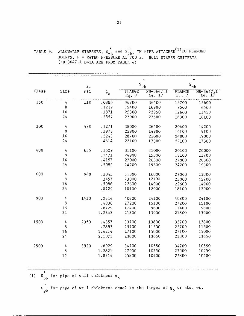
TABLE 9. ALLOWABLE STRESSES, S and Spb, IN PIPE ATTACHED(1)TO FLANGEDJOINTS, P = RATED PRESSURE AT 700 F. BOLT STRESS CRITERIA
(NB-3647.1 DATA ARE FROM TABLE 4)
Class
150
300
400
600
900
1500
2500
Size
16
24
4
8
16
24
16
24
16
24
16
24
16
24
4
8
12
P,psi
110
470
635
940
1410
2350
3920
.0886
.1239
.1871
.2557
.1271
.1979
.3243
.4614
.1529
.2471
.4157
.5986
.2043
.3457
.5986
.8729
,2814
,4936
,8729
,2843
,4357
,7893
,4214
,1071
.6929
1.2821
1.8714
(1) S , for pipe of wall thickness g
PbFLANGE
Eq. 7
36700
19400
25300
23900
38000
22900
28700
22100
31100
24900
27000
24200
31300
23000
22600
18100
40800
27200
17400
21800
33700
25700
27100
23800
34700
27900
25800
NB-3647.1
Eq. 17
36400
16900
22950
23500
26400
14900
22000
17300
31000
15300
20300
19300
16000
12700
14900
12900
24100
15100
9600
13900
13800
11500
15000
13650
10550
10250
10400
PbFLANGE NB-3647.1Eq. 7 Eq. 17
13700
7500
12600
16300
20400
14100
24800
22100
20100
19100
27000
24200
27000
23000
22600
18100
40800
27200
17400
21800
33700
25700
27100
23800
34700
27900
25800
13600
6500
11450
16100
14200
9100
19000
17300
20000
11700
20300
19300
13800
12700
14900
12900
24100
15100
9600
13900
13800
11500
15000
13650
10550
10250
10400
S , for pipe of wall thickness equal to the larger of g or std. wt.pb o
30
classes, Equation (17), which is used in program FLANGE, predicts significantly
higher allowable pipe bending stresses than Equation (7); up to 3.3 times
as much for the 4" - 2,500 lb flanged joint. However, Equation (17) does not
include thermal gradient effects; these, if included, would decrease the
values of allowable pipe bending stress and the results from Equation
(7) might not be overconservative.
NB-3232.2 Maximum Stress
The maximum value of service stress at the periphery of the
bolt cross section resulting from direct tension plus bending and
neglecting stress concentrations must not exceed three times the
tabulated allowable stress intensity values. Stress intensity, rather
than maximum stress, shall be limited to these values when the bolts are
tightened by methods other than heaters, stretchers, or other means
that minimize residual torsion.
To examine the effect of this maximum stress intensity limit
on B16.5 flanged joints, it is necessary to establish
(a) The magnitude of the bending stresses in the bolts
(b) The stress intensity in the bolts - since B16.5
flanges are usually tightened with a wrench that
does produce residual torsion in the bolts.
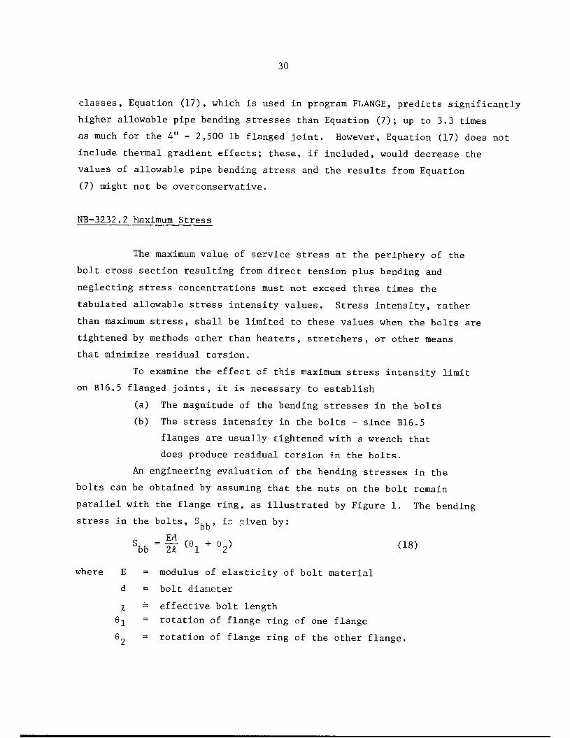
An engineering evaluation of the bending stresses in the
bolts can be obtained by assuming that the nuts on the bolt remain
parallel with the flange ring, as illustrated by Figure 1. The bending
stress in the bolts, S , ±2 given by:
Ed
Sbb = 21 (G1 + V <18>
where E = modulus of elasticity of bolt material
d = bolt diameter
I = effective bolt length
6"l = rotation of flange ring of one flange
9~ = rotation of flange ring of the other flange.

31
Nut face remainsparallel to
ring surface
FIGURE 1. ASSUMPTION USED IN CALCULATING BOLT BENDING STRESS
32
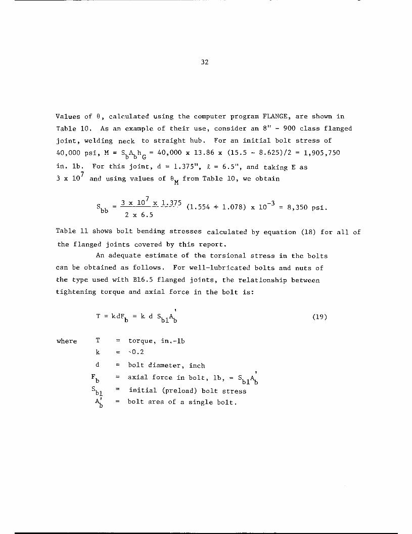
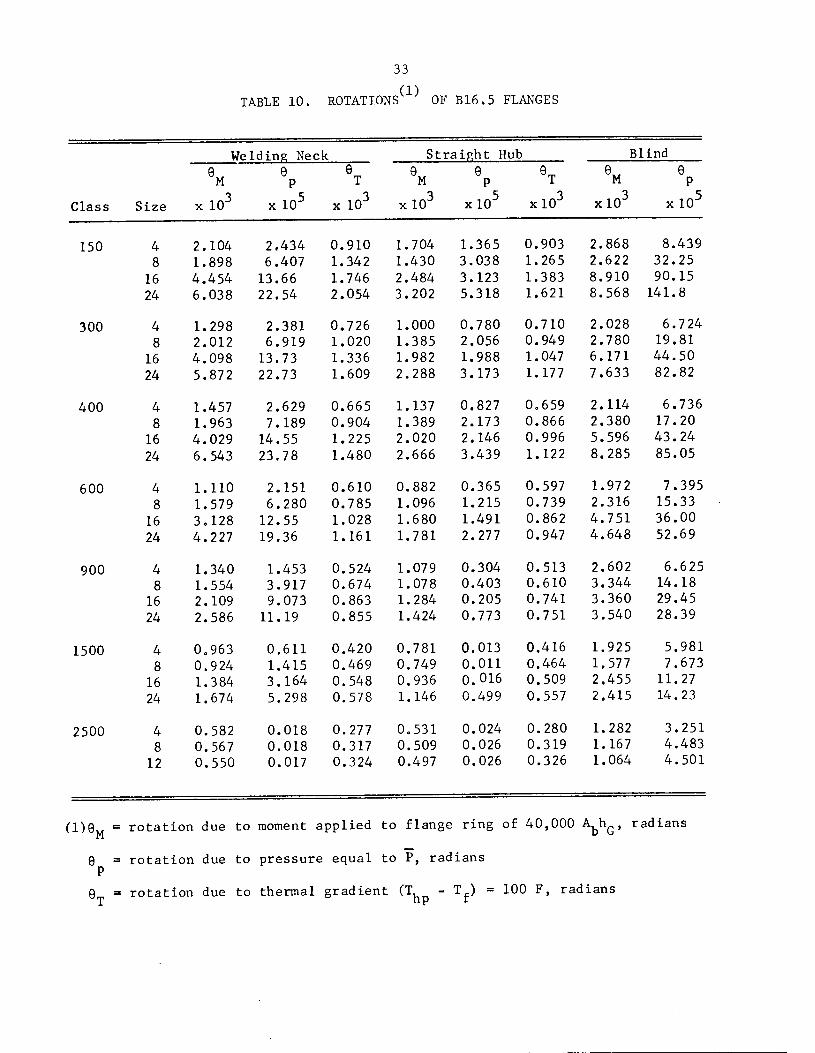
Values of 6, calculated using the computer program FLANGE, are shown in
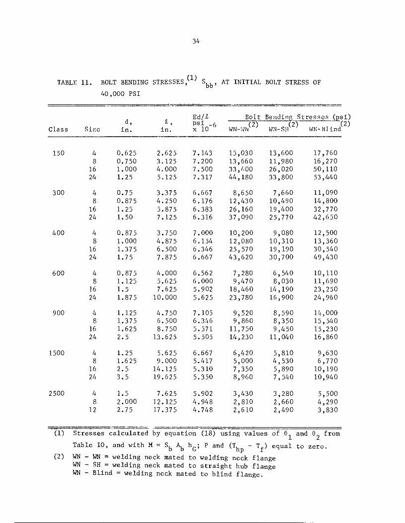
Table 10. As an example of their use, consider an 8" - 900 class flanged
joint, welding neck to straight hub. For an initial bolt stress of
40,000 psi, M = Sih = 40,000 x 13.86 x (15.5 - 8.625)/2 = 1,905,750
in. lb. For this joint, d = 1.375", I = 6.5", and taking E as
3 x 10 and using values of 0„ from Table 10, we obtain
Sbb =3X10 x1'375 (1.554 +1.078) x10"3 =8,350 psi.2 x 6.5
Table 11 shows bolt bending stresses calculated by equation (18) for all of
the flanged joints covered by this report.
An adequate estimate of the torsional stress in the bolts
can be obtained as follows. For well-lubricated bolts and nuts of
the type used with B16.5 flanged joints, the relationship between
tightening torque and axial force in the bolt is:
T=kdFb =kdSblAb' (19)
where T = torque, in.-lb
k = -0.2
d = bolt diameter, incht
Ffe = axial force in bolt, lb, = S A.
Sbl = initial (preload) bolt stressA, = bolt area of a single bolt.
33
(1)TABLE 10. ROTATIONS OF B16.5 FLANGES
Welding Neck Straight Hub Blind
M
3Class Size x 10 x 10" x 10"
M
xlO2
e
xlO" xlO"
M
xlO" x 10"
150 4 2.104 2.434 0.910 1.704 1.365 0.903 2.868 8.439
8 1.898 6.407 1.342 1.430 3.038 1.265 2.622 32.25
16 4.454 13.66 1.746 2.484 3.123 1.383 8.910 90.15
24 6.038 22.54 2.054 3.202 5.318 1.621 8.568 141.8
300 4 1.298 2.381 0.726 1.000 0.780 0.710 2.028 6.7 24
8 2.012 6.919 1.020 1.385 2.056 0.949 2.780 19.81
16 4.098 13.73 1.336 1.982 1.988 1.047 6.171 44.50
24 5.872 22.73 1.609 2.288 3.173 1.177 7.633 82.82
400 4 1.457 2.629 0.665 1.137 0.827 0.659 2.114 6.736
8 1.963 7.189 0.904 1.389 2.173 0.866 2.380 17.20
16 4.029 14.55 1.225 2.020 2.146 0.996 5.596 43.24
24 6.543 23.78 1.480 2.666 3.439 1.122 8.285 85.05
600 4 1.110 2.151 0.610 0.882 0.365 0.597 1.972 7.395
8 1.579 6.280 0.785 1.096 1.215 0.739 2.316 15.33
16 3.128 12.55 1.028 1.680 1.491 0.862 4.751 36.00
24 4.227 19.36 1.161 1.781 2.277 0.947 4.648 52.69
900 4 1.340 1.453 0.524 1.079 0.304 0.513 2.602 6.625
8 1.554 3.917 0.674 1.078 0.403 0.610 3.344 14.18
16 2.109 9.073 0.863 1.284 0.205 0.741 3.360 29.45
24 2.586 11.19 0.855 1.424 0.773 0.751 3.540 28.39
1500 4 0.963 0.611 0.420 0.781 0.013 0.416 1.925 5.981
8 0.924 1.415 0.469 0.749 0.011 0.464 1.577 7.673
16 1.384 3.164 0.548 0.936 0.016 0.509 2.455 11.27
24 1.674 5.298 0.578 1.146 0.499 0.557 2.415 14.23
2500 4 0.582 0.018 0.277 0.531 0.024 0.280 1.282 3.251
8 0.567 0.018 0.317 0.509 0.026 0.319 1.167 4.483
12 0.550 0.017 0.324 0.497 0.026 0.326 1.064 4.501
meM - rotation due to moment applied to flange ring of 40,000 W radians
9™, =
rotation due to pressure equal to P, radians
rotation due to thermal gradient (T - Tf) = 100 F, radians
34
TABLE 11. BOLT BENDING STRESSES, ' S AT INITIAL BOLT STRESS OF
40 ,000 PSI
Ed/£ Bolt Bending Stresses (ps
Class Size
d,in.
£,in.
psi _6x 10
(2)WN-WN
(2)WN-SH WN-Blind
150 4 0.625 2.625 7.143 15,030 13,600 17,760
8 0.750 3.125 7.200 13,660 11,980 16,270
16 1.000 4.000 7.500 33,400 26,020 50,110
24 1.25 5.125 7.317 44,180 33,800 53,440
300 4 0.75 3.375 6.667 8,650 7,660 11,090
8 0.875 4.250 6.176 12,430 10,490 14,800
16 1.25 5.875 6.383 26,160 19,400 32,770
24 1.50 7.125 6.316 37,090 25,770 42,650
400 4 0.875 3.750 7.000 10,200 9,080 12,500
8 1.000 4.875 6.154 12,080 10,310 13,360
16 1.375 6.500 6.346 25,570 19,190 30,540
24 1.75 7.875 6.667 43,620 30,700 49,430
600 4 0.875 4.000 6.562 7,280 6,540 10,110
8 1.125 5.625 6.000 9,470 8,030 11,690
16 1.5 7.625 5.902 18,460 14,190 23,250
24 1.875 10.000 5.625 23,780 16,900 24,960
900 4 1.125 4.750 7.105 9,520 8,590 14,0008 1.375 6.500 6.346 9,860 8,350 15,540
16 1.625 8.750 5.571 11,750 9,450 15,230
24 2.5 13.625 5.505 14,230 11,040 16,860
1500 4 1.25 5.625 6.667 6,420 5,810 9,6308 1.625 9.000 5.417 5,000 4,530 6,770
16 2.5 14.125 5.310 7,350 5,890 10,19024 3.5 19.625 5.350 8,960 7,540 10,940
2500 4 1.5 7.625 5.902 3,430 3,280 5,5008 2.000 12.125 4.948 2,810 2,660 4,290
12 2.75 17.375 4.748 2,610 2,490 3,830
(1) Stresses calculated by equat:ion (18) using values of 6 and 6 from
,(2)
Table 10, and with M = Sfo Afo hG; P and (Th - Tf) equal to zero.(2) WN - WN = welding neck mated to welding neck flange
WN - SH = welding neck mated to straight hub flangeWN - Blind = welding neck mated to blind flange.
35
The constant k represents frictional resistance between threads plus
frictional resistance between nut and flange. Approximately one-half
of the torque is resisted by thread friction; the other half by nut/
flange friction. Accordingly, the bolt is subjected to a torsional
load of T = T/2. The shear stress in the bolt, Sb2, is then:
sb2 •\ Msb! *4-x -4 -2 ksbi (2o)ird
The stress intensity, including the bending stress, is then given by:
\ - [(sbi +sbb)2 +4x(2ksbi)2] *2 (2i)According to NB-3232.2, the value of S must be less than 3Sm> From
equating S, to 3S we obtain:
^ = r(3s /SU1)2- 16k2"l "1 (22)S I m bl Jbl L
For SA-193 Grade B7, bolt material at 100 F, S^ = 35,000 for d± 2.5";S = 31,600 psi for d >2.5". With an average initial bolt stressm
S, =40,000 psi, Equation (22) gives:bl
(S, ,./St1) maximum = 1.500 for d^ 2.5"bb bl
(S../S.,) maximum = 1.231 for d> 2.5"bb bl
Using the results of Table 11 (i.e., S ), it is apparent that for an initial
bolt stress of S = 40,000 psi, the ratios of sbb/sbl are weH below theratios permitted by NB-3232.2 and that NB-3232.2 is met for preload bolting
conditions.
To check whether the NB-3232.2 criterion that the maximum bolt
stress must be less than 3S is met for operating conditions requires

36
a knowledge of the time history of P , P, T, , T, , and T . Once these
four quantities are known, the average bolt stress S can be obtained
by Equation (11), the bolt bending stress Sbb can be obtained by Equation11 and Equation (18), and the shear stress S can be obtained by Equation
(20). These three values can then be used in Equation (21) to determine
whether the maximum bolt stress is less than 3S , as required by NB-3232.2.
As an example, consider an 8" - 900 class flanged joint, welding
neck-to-straight hub. The initial bolt stress is 40,000 psi. The assumed
operating condition to be checked is:
P = 1,410 psi
P = 900 psi
P =2,700 psieq rT, = 600 F (S for bolts = 28,400 psi)b m » r /
T^ = 700 FhpT = 650 F
E2/E1 = 0.90
Equation (11) and the a-values from Tables 5 and 6 give:
Sb2 =40,000 x0.90 -400 x~^ -500 x±^ -3400 x0.90 x^~- 4600 x 50_
100
= 36000 - 1200 - 783 + 3060 - 2300
= 34,780 psi
We note that the average stress of S = 34,780 psi meets NB-3232.1;
i.e., 34,780 is less than 2 S = 2 x 28,400 - 56,800 psi. Using the values
from Table 10 for the assumed 8" - 900 class welding neck-to-straight hub
flanged joint and the assumed operating conditions:
6M =(1.554 +1.078) x10~3 at Sfel =40,000 psi=2.632 x10"3 x|^|| =2.289 x10_3 at Sb2 =34,780 psi*
0p =(3.917 +0.403) x10~5 x^-°- =6.768 x10_5
6T =(0.674 +0.610 x10"3 x-J| =0.642 x10~3
* The procedure used here is approximately correct, but, more precisely,6., is proportional to the flange moment rather than bolt load. TheM
computer program FLANGE gives the change in moment so that the moreprecise results can be used.
37
Accordingly, the flange rotation at the operating conditions is-3
2.999 x 10 radians.
The flange bending stress from equation (18) with E = 3 x 10 psi, d = 1.375"
and I = 6.5" is
=Ed (6) 6.346 x106 x2.999 x10~3 =9,520 psibb 2£ 2
From Equation (20), the initial shear stress is 2 x 0.2 x 40,000 =
16,000 psi. This shear stress will decrease by the ratio E /E ;
assumed for this example to be 0.90. Accordingly, the maximum stress
intensity at the assumed operating conditions is:
Average bolt stress = 34,780 psi
Bending bolt stress = 9,520 psi
Shear bolt stress = 14,400 psi
Maximum stress intensity = (44,300) + 4 x 14,400
= 52,800 psi.
Because 53,090 psi is less than 3S at 600 F (85,200 psi in thisr m
example) the criterion of NB-3232.2 is satisfied.
NB-3232.3 Fatigue Analysis of Bolts
NB-3232.3 requires that changes in bolt stresses due to the
postulated history of operating conditions must be determined and evalua
ted. In the following discussion of fatigue analysis, a "fatigue
strength reduction factor" of 4.0 will be used to account for the
"notch" at the root of the bolt threads.
1/2
The fatigue analysis is not required if the conditions of NB-3222.4(d)are met. It is difficult for the authors to see the relevance of
NB-3222.4(d) to bolted flanged joints. First, the bolt tightening/untightening cycle is completely ignored; this is probably themajor significant cycle involved. Second, the definition of"adjacent points" does not seem to have any meaning because amajor temperature gradient to be considered is that between theflanges and bolts.

38
One of the postulated cycles may consist of bolting and un
bolting the flanged joint a postulated number of times during the service
life. If the average initial bolt stress is 40,000 psi, obtained by
tightening with a wrench, then the peak stress range, S , due to tightening/
untightening, is obtained from equation (21) using k = 0.2, S, n = 40,000.bl
Equation (21), multiplied by 4.0 for the notch at the root of the bolt
threads, gives:
Sp =[(40,000 +Sbb)2 +1.024 x10⁹] 1/2 x4.0 (23)Values of Sbb are given in Table 11 for an initial bolt load of
40,000 psi. Using these in Equation (23) gives the peak stress
ranges shown in Table 12. From Code Figure 1-9.4, with S = S /2a p
and using the curve labeled "Max. nominal stress = 3.OS ", wem
obtain the permissible cycles, N , shown in Table 12. It can be seen
in Table 12 that the number of tightening/untightening cycles, N , is
large even for the worst flange (225 cycles for the 24" - 400 class,
welding neck-to-blind flanged joint). The values of N shown in
Table 12 are far in excess of the number of tightening/untightening cyclesnormally encountered in B16.5 flanged joints.
In operation, cyclic bolt stresses would be superimposed on
the initial bolt stresses. The complete fatigue analysis would requirethat the history of P P, T T and T be known. Knowing that
history, the bolt stress variations can be obtained from the data
presented herein, for the flanged joints covered herein, or more
generally, by use of the computer program FLANGE.
The fatigue analysis procedure can be illustrated by
continuing the example of the 8" - 900 class flanged joint
and the assumed set of operating conditions. As developed
previously, the operating conditions give a maximum stress in
tensity in the bolts of 53,090 psi. The peak stress intensity
is 4 x 53090 = 212,360 psi. The peak stress intensity at the
40,000 psi preload condition is 232,000 psi (see Table 12).
Assuming cycles between the operating conditions and preload

39
TABLE 12. BOLT FATIGUE ANALYSIS, STRESS RANGE AND ALLOWABLEDESIGN CYCLES, N , FOR BOLT TIGHTENING/UNTIGHTENINGCYCLE
WN-WN WN-SH WN-Blind
Class
150
300
400
600
900
1500
2500
Size
4
8
16
24
4
8
16
24
4
8
16
24
16
24
16
24
16
24
4
8
12
Stress,
ksi^
255
250
320
360
233
246
294
334
238
245
292
358
228
236
267
285
236
237
243
252
226
221
229
234
216
214
213
Cycles,
(2)N.D
455
472
305
247
534
485
354
282
514
489
358
250
555
522
420
374
522
518
496
465
564
587
551
530
611
621
626
Stress,
ksi^
250
244
293
322
230
239
270
293
234
238
269
310
226
231
252
261
233
232
236
241
224
219
224
229
215
213
213
Cycles,
<2)471
492
356
301
547
511
411
356
530
514
414
322
564
542
465
437
534
538
522
503
573
596
573
551
616
626
626
Stress,
264
259
293
395
241
254
318
355
246
249
310
380
238
243
284
290
251
256
255
261
236
227
238
241
223
219
217
(1) Stress Range from Equation (23)(2) Allowable Design Cycles from Code Figure 1-9.4, Curve labeled
"Max. nominal stress = 3.0 Sm
Cycles,
(2)ND
428
443
356
210
503
458
308
253
485
475
322
225
514
496
376
362
468
452
455
437
522
559
514
503
577
596
606

40
conditions then gives a peak stress intensity range for those
cycles of 232,000 - 212,000 = 20,000 psi. Entering Code Figure
1-9.4, with S = 20,000/2 we find the design cycles to be 55,000.a.
Recalling that the example conditions correspond to going from
shutdown to operating and back to shutdown conditions, it is apparent
that exceeding the Code fatigue limitations for any credible operating
history is unlikely. This result was probably obvious to many readers
who recognize that in a flanged joint with adequately high preload bolt
stresses, the variations in bolt stresses due to subsequently
applied loadings are relatively small.
Summary of Results on Bolt Areas and Bolt Stresses
Calculations were made on a representative sampling of B16.5
flanged joints with:
(a) Rated pressures of ANSI B16.5 - 1968 for carbon steel
flange material
(b) Gasket O.D. = raised face O.D.
Gasket I.D. = pipe O.D.
m = 2.75, y = 3,700
(c) Bolt material: SA-193 Grade B7
From the results of these calculations, the following conclusions
can be drawn.
(1) The bolting area is sufficient to meet the requirement
of NB-3647.1(b) which states that "Equations (3) and (4)
of XI-3220 shall be used to establish minimum bolt area...".
(2) The limitation on bending stresses imposed by the use of
P is such that the allowable pipe bending stress in
attached pipe ranges from 13 to 48 percent (average of
28 percent) of that permitted by Equation (12) in
NB-3653.6. The values cited are specifically forit
SA106 Grade B pipe at 700 F; Table 4, S , , values cal-Pb
culated according to the rules of NB-3647.1.
41
(3) The limitation on bending stresses by a seemingly
more rational analysis is such that the allowable pipe
bending stress in attached pipe ranges from 15 to 81
percent (average of 45 percent) of that permitted by
Equation (12) in NB-3653.6. The values cited are
specifically for SA 106 Grade B pipe at 700 F, Table 9,ii
S , values calculated using program FLANGE.
(4) Calculations indicate that a preload average bolt stress of
around 40,000 psi is appropriate for B16.5 flanged joints.
This initial bolt stress is permitted by the Code.
(5) With a preload average bolt stress of 40,000 psi, the
Code limit of 3S for combined average, bending and
torsional stress is met.
(6) With a preload average bolt stress of 40,000 psi, the
fatigue limits of the Code will be satisfied for any
ordinarily anticipated loading history.
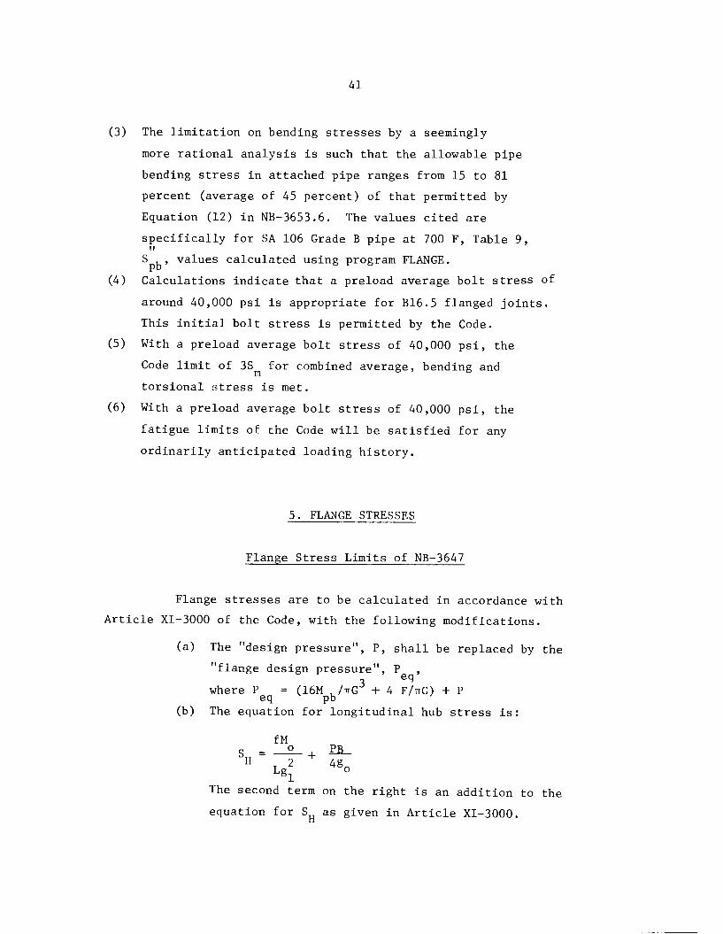
5. FLANGE STRESSES
Flange Stress Limits of NB-3647
Flange stresses are to be calculated in accordance with
Article XI-3000 of the Code, with the following modifications.
(a) The "design pressure", P, shall be replaced by the
"flange design pressure", P ,3 6q
where P = (16M , /ttG + 4 F/ttG) + Peq pb
(b) The equation for longitudinal hub stress is:
fM
H t2 + 4g0
The second term on the right is an addition to the
equation for SR as given in Article XI-3000.
42
(c) The allowable stress limits are:
S , S and S not greater than 1.5 S .H R 1 ni
The stress limits in Article XI-3000 essentially are:
SR and ST < S
Su < 1.5S
(SR + SR)/2<S
(ST + SR)/2<S
Stresses of Rated Pressures, Zero Pipe Bending Moment
Table 13 shows the values of maximum flange stresses calculated
according to the rules of NB-3647 for a pressure equal to the rated pressure
at 100 F and with S = Su = 35,000 psi; the value of S at 100 F for SA 193a b m
Grade B7 bolt material. The locations and directions of the calculated
stresses are shown in Figure 2. The bending moment in the attached
pipe is assumed to be zero. If the flanges are made of SA-105 material,
then S = 23,300 psi at 100 F and the maximum allowable flange stress is
1.5 x 23,300 = 34,950 psi. It can be noted in Table 13 that the
following flanges have maximum stresses exceeding 34,950 psi:
Welding Neck: 24", 300, 400 and 600 classes.
Blind: 24" - 400, 16" - 900, 4" - 1,500 and 4" - 2,500.
Table 14 shows the calculated values of maximum flange
stresses in accordance with Appendix II of Section VIII - Div. 1.
The calculated stresses in Table 14 are different than those in Table 13
for three reasons.
(1) In Table 13, the maximum stress is usually S + PB/4g ,H o
whereas in Table 14, the controlling stress is usually
(SH+SR)/2.
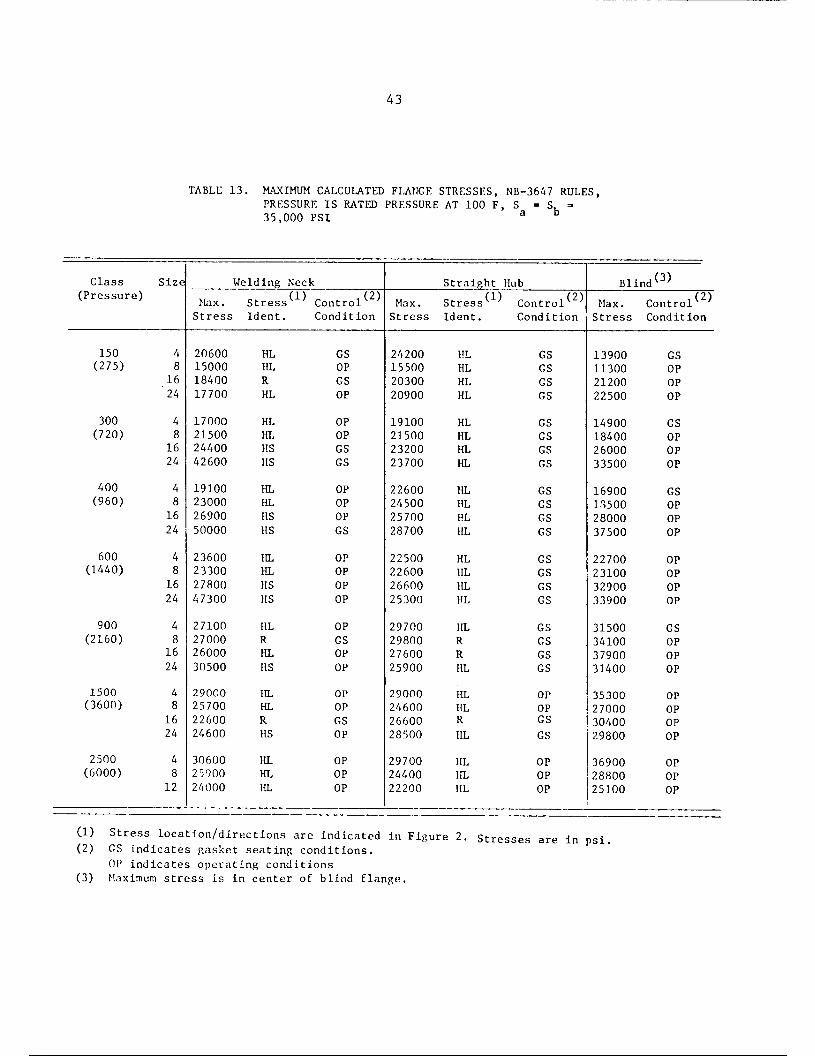
43
TABLE 13. MAXIMUM CALCULATED FLANGE STRESSES, NB-3647 RULES,PRESSURE IS RATED PRESSURE AT 100 F, S = St35,000 PSI
Class Size Welding Neck Straight Hub Blind<3>(Pressure)
Max. Stress,(1) Co„trol(2> Max. Stress(1^ (2)Controlv ; Max.
,(2)Control '
Stress Ident. Condition Stress Ident. Condition Stress Condition
150 4 20600 HL GS 24200 HL GS 13900 GS
(275) 8 15000 HL OP 15500 HL GS 11300 OP
16 18400 R GS 20300 HL GS 21200 OP
24 17700 HL OP 20900 HL GS 22500 OP
300 4 17000 HL OP 19100 HL GS 14900 GS
(720) 8 21500 HL OP 21500 HL GS 18400 OP
16 24400 HS GS 23200 HL GS 26000 OP
24 42600 HS GS 23700 HL GS 33500 OP
400 4 19100 HL OP 22600 HL GS 16900 GS(960) 8 23000 HL OP 24500 HL GS 13500 OP
16 26900 HS OP 25700 HL GS 28000 OP
24 50000 HS GS 28700 HL GS 37500 OP
600 4 23600 HL OP 22500 HL GS 22700 OP(1440) 8 23300 HL OP 22600 HL GS 23100 OP
16 27800 HS OP 26600 HL GS 32900 OP
24 47300 HS OP 25300 HL GS 33900 OP
900 4 27100 HL OP 29700 HL GS 31500 GS
(2160) 8 27000 R GS 29800 R GS 34100 OP
16 26000 HL OP 27600 R GS 37900 OP
24 30500 HS OP 25900 HL GS 31400 OP
1500 4 29000 HL OP 29000 HL OP 35300 OP(3600) 8 25700 HL OP 24600 HL OP 27000 OP
16 22600 R GS 26600 R GS 30400 OP
24 24600 HS OP 28500 HL GS 29800 OP
2500 4 30600 HL OP 29700 HL OP 36900 OP
(6000) 8 25900 HL OP 24400 HL OP 28800 OP
.—. .—.
12 24000 HL OP 22200 HL OP 25100 OP
(1) Stress location/directions are indicated in Figure 2. Stresses are in psi.(2) GS indicates gasket seating conditions.
OP indicates operating conditions(3) Maximum stress is in center of blind flange.

44
Stress Identification Nomenclature
This Report ASME VIII-1
FIGURE 2. IDENTIFICATION OF STRESSES CALCULATED BY CODE
PROCEDURE

45
TABLE 14: CONTROLLING CALCULATED FLANGE STRESSES, SECTION VIII - DIV. 1 RULES,PRESSURE IS RATED PRESSURE AT 100 F, S =
a25,000 PSI
Welding Neck Straight HubStress^ ;
Blind ControllingClass Control Stress(l) Control Max Moment
(Pressure) Size Stress ,
psiIden. Stress,
psi- Iden. Stress,
psi(2)
150 4 12400 HR 14300 HR 11000 GS
(275) 8 8600 HR 9600 HR 11300 GS
16 14400 R 15600 HR 21200 GS
24 12200 HR 13900 HR 22500 GS
300 4 10800 HR 12800 HR 13800 GS
(720) 8 12000 HR 14500 HR 18400 GS
16 17800 HR 18400 HR 26000 GS
24 25200 HR 19000 HR 33500 GS
400 4 12300 HT 14700 HR 15200 GS
(960) 8 12400 HT 15300 HR 18500 OP
16 18900 HR 19700 HR 28000 GS
24 29300 HR 22500 HR 37500 GS
600 4 15100 HR 17600 HR 22700 OP
(1440) 8 13800 HR 17100 HR 23100 OP
16 19300 HR 21600 HR 33900 GS
24 26800 HT 19800 HR 33900 OP
900 4 19700 HR 22800 HR 29700 GS
(2160) 8 22200 R 24500 R 34100 GS
16 21800 R 24500 R 37900 OP
24 19100 HR 20300 HR 31400 GS
1500 4 21300 HR 2530u HR 35300 OP
(3600) 8 16500 HR 19500 HR 27000 OP
16 18400 R 21700 R 30400 GS
24 16200 HT 20900 HR 29800 GS
2500 4 22600 HT 24600 HR 36900 OP
(6000) 8 17800 HR 19800 HR 28800 OP
12 15500 HR 17100 HR 25100 OP
(1) HR = (St + SR)/2, R HT'H ' "R""* " R'
(2) Controlling moment for welding neck and straight hub. GS = gasket seating,OP = operating. For blind flanges, the operating moment controls for all
but the 4" - 150 class.
<SH + ST)/2
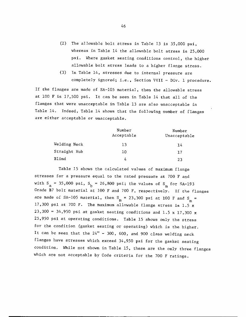
46
(2) The allowable bolt stress in Table 13 is 35,000 psi,
whereas in Table 14 the allowable bolt stress is 25,000
psi. Where gasket seating conditions control, the higher
allowable bolt stress leads to a higher flange stress.
(3) In Table 14, stresses due to internal pressure are
completely ignored; i.e., Section VIII - Div. 1 procedure.
If the flanges are made of SA-105 material, then the allowable stress
at 100 F is 17,500 psi. It can be seen in Table 14 that all of the
flanges that were unacceptable in Table 13 are also unacceptable in
Table 14. Indeed, Table 14 shows that the following number of flanges
are either acceptable or unacceptable.
Number Number
Acceptable Unacceptable
Welding Neck 13 14
Straight Hub 10 17
Blind 4 23
Table 15 shows the calculated values of maximum flange
stresses for a pressure equal to the rated pressure at 700 F and
with S = 35,000 psi, S, = 26,800 psi; the values of S for SA-193a d m
Grade B7 bolt material at 100 F and 700 F, respectively. If the flanges
are made of SA-105 material, then S = 23,300 psi at 100 F and S =m m
17,300 psi at 700 F. The maximum allowable flange stress is 1.5 x
23,300 = 34,950 psi at gasket seating conditions and 1.5 x 17,300 x
25,950 psi at operating conditions. Table 15 shows only the stress
for the condition (gasket seating or operating) which is the higher.
It can be seen that the 24" - 300, 600, and 900 class welding neck
flanges have stresses which exceed 34,950 psi for the gasket seatingcondition. While not shown in Table 15, these are the only three flangeswhich are not acceptable by Code criteria for the 700 F ratings.

47
TABLE 15: MAXIMUM CALCULATED FLANGE STRESSES, NB-3647 RULES,PRESSURE IS RATED PRESSURE AT 700 F, S = 35,000PSI, S, 26,800 PSI
Welding Neck
—
Straight Hub Blind(3)Class Max. Stress(1) Control(2) Max. Stress(1) Control() Max.
(3)Control. '
Size Stress Iden. Condition Stress Iden. Condition Stress Condition
150 4 20600 HL GS 24200 HL GS 13900 GS
(110) 8 13600 HL GS 15500 HL GS 8100 GS
16 17500 R GS 19300 HL GS 16800 GS
24 16200 HL GS 19200 HL GS 11900 GS
300 4 14800 HL GS 18200 HL GS 142Q0 GS
(470) 8 16200 HL GS 20400 HL GS 13600 GS
16 23300 HS GS 22200 HL GS 20800 GS
24 40600 HS GS 22600 HL GS 21800 OP
400 4 17300 HL GS 21700 HL GS 16200 GS
(635) 8 17100 HL GS 22300 HL GS 13600 GS
16 25700 HS GS 24700 HL GS 21400 GS
24 47900 HS GS 27500 HL GS 24800 OP
600 4 17600 HL GS 21200 HL GS 19600 GS
(940) 8 16300 HL GS 21300 HL GS 17100 GS
16 23500 HS GS 25200 HL GS 24200 GS
24 43900 HS GS 24000 HL GS 22100 OP
900 4 23400 HL GS 28100 HL GS 29700 GS
(1410) 8 19100 HL GS 28100 R GS 29600 GS
16 23200 R GS 25900 R GS 24900 GS
24 26100 HS GS 24500 HL GS 22400 GS
1500 4 21400 HL GS 26500 HL GS 30300 GS
(2350) 8 18200 HL GS 22400 HL GS 21500 GS
16 21400 R GS 25200 R GS 26900 GS
24 19100 HS GS 27000 HL GS 24000 GS
2500 4 22400 HL GS 25300 HL GS 31400 GS
(3920) 8 18500 HL GS 21000 HL GS 23900 GS
12 17300 HL GS 19500 HL GS 21000 GS
(1) Stress location/directions are indicated in Figure 2.(2) GS indicates gasket seating conditions
OP indicates operating conditions
(3) Maximum stress is in center of blind flange.

48
Allowable Pressures, Zero Pipe Bending Moment
It is pertinent to calculate the allowable pressure for
the flanges with conditions as used in Tables 13, 14, and 15; i.e.,
under the following conditions.
(a) 100 F, S = S, = 35,000 psi, max. flange stress =3. D
34,950 psi
(b) 100 F, S = S = S, = 25,000 psi; controlling flange stressa a b
17,500 psi
(c) 700 F, S = 35,000 psi, S = 26,800 psi, max. flange3. D
stress = 25,950 psi.
Calculated maximum allowable pressures are shown in Table 16. It is
apparent that the "pressure ratings" are erratic and illogical. Note
that the 24" - 400 class welding neck flange has a zero maximum pressure
rating. The 24" - 600 class welding neck flange has a lower pressure
rating than the 24" - 150 class welding neck flange. The 24" - 400 class
straight hub flange has a lower pressure rating than the 24" - 150 class
straight hub flange.
The reason for these illogical pressure ratings is due to
the Code method of calculating loads under gasket seating conditions
using the equation:
n (Am +V Sa (24)w = _
The value of A is the larger ofm
•[•W = I(tt/4) G2 + 2TTbGm P/Sb (25)
and
Wm2 = ^y/Sa (26)

49
TABLE 16. MAXIMUM ALLOWABLE PRESSURES (PSI)
Welding Neck
100 F 100 F 700 F
St
100* Fraight IYob F
lub Blind
700 F 100 F 100 F 700 F
Class Size NB-3647 VIII-1 NB-3647 NB-3647 VIII-1 NB-3647 NB-3647 VIII-1 NB-3647
150 4 760 680 560 830 590 620 1160 580 860
8 640 590 480 760 530 560 850 420 63016 610 450 450 770 420 560 450 220 340
24 540 470 400 650 420 480 430 210 320
300 4 1480 890 1100 1730 1120 1280 1830 910 1350
8 1170 1050 870 1320 870 980 1360 680 1010
16 1050 0+ 780 1550 86°* 1150 970 490 720
24 630 0+ 470 1330 570 990 750 380 560
400 4 1760 1610 1310 1980 1330 1470 2210 1110 16408 1470 1350 1090 1570 110°* 1170 1820 910 1350
16 1250 0+ 930 1740 67°* 1290 1200 600 890
24 0+ 0+ 0+ 1490 390 1110 890 450 660
600 4 1630 1670 1210 2360 1430 1750 2220 1110 1650
8 2160 1820* 1600 2320 1470* 1720 2170 1090 1610
16 1810* 1130 1340 2230 81°* 1650 1530 770 1140
24 450 0+ 790 2140 1060 1590 1490 740 1100
900 4 2780 1630* 2070 2980 1050* 2210 2540*
620* 1890
8 3060 °* 2270 3410 82°* 2530 2220 650 1650
16 2910 1520* 2160 3080 112°* 2290 1990 1000 1480
24 2480 17 30 1840 3280 1480 2430 2400 1200 1780
1500 4 4340 2960 3220 4340 2040* 3220 3560*
1130 2640
8 4890 3820* 3630 5110 3230* 3800 4660 2330 3460
16 5650 3190 4200 5810 2000* 4310 4140 2070 3070
24 5110 3960 3790 4780 2250 3550 4230 2120 3140
2500 4 6850 4640 5090 7050 4200* 5230 5680 1720* 4210
8 8100 5890 6010 8590 5300 6380 7270 3640 5400
12 8740 6780 6490 9450 6120 7020 8340 4180 6200
+ Stress at gasket seating conditions exceeds allowable flange stress.* Maximum allowable pressure controlled by gasket seating conditions.
No symbol; maximum allowable pressure controlled by operating conditions.

50
If W 1 is larger than W (it almost always is for Table 16 calculations),ml mz
the flange moment for seating conditions is:
M = Wh =gs G
|"(ir •]/4)G2 +2TTbGm| P/Sb +kA -|-~ (27)
The flange stresses are proportional to M ; i.e.. Sr = K M , wheregs , ' f _ gsK is the proportionality constant. If S = K M , where Sf
.ing for VIII-1) flange stress
flange stress, then:
maximum (or controlling for VIII-1) flange stress and S .. = allowable3. XX
KM = s ..gs all
K* Jf(7r/4)G2 +2-rTbGml P/Sb +Afc j
Solving equation (28) for P gives:
P =
2Sall
S h K*h\
(tt/4)G + 2irbGm
S h„a G
(28)
(29)
As an example, for the 24" - 600 class welding neck flange with $a^ =34,950 psi and S = S = 35,000 psi. For this flange, A^ = 55.296 in. ,h = 3.3257", K* = 0.009232 in."3 and [(tt/4)G2 + 2TrbGm] = 750.49 in.2.With this specific data, Equation (29) gives:
69,900-3
35,000 x 3.3257 x 9.232 x 10
= 455 psi
- 55.29635,000
750.49
51
For the 24" - 400 class welding neck flange, Equation (29) gives P =
5.18 psi. However, for this particular flange, W is larger than W .
Accordingly,
s'.K-f-f* +Ab SaV2 (30)a
' -3For the 24" - 400 class welding neck flange; K = 0.01484 in. , nbGy =
138,040 lb, A^ =47.52 in.2 and h =2.8257 in. With S =35,000 psi,
Sf = 0.01484 (138,040 + 35,000 x 47.52) x 2.8257/2
= 37,770 psi.
Because 37,770 is greater than S = 34,950 psi, the Code evaluation
is that the 24" 400 class welding neck flange is not acceptable for
any pressure. It is interesting to note that even if y = 0, the flange
stress by Equation (30)is 34,871 psi hence, the Code evaluation indicates
that this particular flange, made of material such that S = 23,300 psi
or less, is not acceptable for any pressure using any gasket.
Allowable Pipe Bending Stresses at Rated Pressure
Allowable pipe bending stresses as limited by the bolting
are shown in Table 4 and Table 9. These are based on internal pressure
equal to the rated pressure at 700 F. However, NB~3647.1 appears to be
written so that another limit is imposed on pipe bending stresses by
the limits on allowable flange stresses. Note that NB-3647.1(a) states
that P_ is to be used in XI-3220 and XI-3230. Because XI-3230 is on
"Flange Moments", the flange stresses will obviously depend upon the3
magnitude of P = 16 M . /ttG and M , , the bending moment in theeq pb pb &
attached pipe.

52
The allowable pipe bending stresses, as limited by the flange
stress, are shown in the first two columns of Table 17. Also shown, for
comparison, are the allowable pipe bending stresses as limited by the
bolt stress; taken from Table 9.
Table 17 data are for flanges made of SA-105 material (S =m
17,300 psi at 700 F) and bolts made of SA-193 Grade B7 (S = 26,800 psi
at 700 F).
It may be seen in Table 17 that the 24" - 400 and 24" - 600
class welding neck flanges have zero allowable pipe bending stress;
actually, the results give negative allowable pipe bending stresses
because the rated pressure is higher than the maximum allowable pressure
(see Table 16). The 24" - 300 class allowable pipe bending stress is
essentially zero; in Table 16, the allowable pressure is shown as equal
to the rated pressure, but before round off the allowable pressure was
calculated as 0.64 psi higher than the rated pressure.
It can be seen in Table 17 that the NB-3647 rules place severe
restrictions on permissible bending stresses in the attached pipe. The
large sizes of B16.5 flanges, while probably less capable of carrying high
bending stresses in the attached pipe than the smaller sizes, have never
theless been used for many years in piping systems where significant
bending moment loads were imposed on the flanged joints.
Basic Theory Flange Stresses
In the preceding section on "Flange Stress Limits of NB-3647",
we have followed the Code procedure for calculating flange stresses. In
so doing, we have arrived at some seemingly contradictory results;
B16.5 flanges which have a long and satisfactory use history are shown
to not meet the Code criteria and, in one extreme case (the 24" - 400
class) the flanges will not meet Code criteria for any pressure with
any gasket; even with zero pipe bending moment. The Code restrictions
on allowable pipe bending stresses appear to be highly questionable for
large size flanges.

53
TABLE 17. ALLOWABLE BENDING STRESSES IN PIPE ATTACHED TO
FLANGED JOINT, P = RATED PRESSURE AT 700 F.PIPE WALL THICKNESS = g .
Flange Stress() Bolt Stress(2)Class Welding Straight NB- Program(P) Size Neck Hub 3647 FLANGE
150 4 28700 25000 36400 36700(110) 8 21500 19700 16900 19400
16 21400 19700 22950 25300
24 17700 15800 23500 23900
300 4 32600 29300 26400 38000
(470) 8 16600 15000 14900 22900
16 11500 18000 22000 28700
24 19 13000 17300 22100
400 4 28400 25000 31000 31100
(635) 8 15000 12600 15300 24900
16 8000 13500 20300 27000
24 0 9100 19300 24200
600 4 7600 18700 16000 31300(940) 8 16100 13600 12700 23000
16 7700 10300 14900 22600
24 0 8700 12900 18100
900 4 14200 13500 24100 40800.(1410) 8 14700 14000 15100 27200
16 10100 8700 9600 17400
24 5000 9600 13900 21800
1500 4 11800 9500 13800 33700(2350) 8 12900 11300 11500 25700
16 16200 12400 15000 27100
24 10900 6900 13650 23800
2500 4 9400 9100 10550 34700(3920) 8 12000 11700 10250 27900
12 13000 12800 10400 25800
(1) Allowable pipe bending stress, psi, as limited by flange stresscriterion.
(2) Allowable pipe bending stress, psi, as limited by bolt stresscriterion. From Table 9.

54
The observation that B16.5 flanges do not necessarily meet
the Code criteria has been brought to the attention of the ASME Boiler
Code Committee many times; the standard response has been that B16.5
flanges are accepted by the Code on the basis of successful
operating history. However, it is pertinent to look in a more
realistic way at calculated stresses in flanges and their significance.
For this purpose, we will present in the following some flange stress
calculations obtained using the computer program FLANGE.
In the Code procedure, a number of somewhat arbitrary
aspects are involved in the design procedure; e.g., the effective
gasket width, b ; the effective gasket diameter, G; the gasket factors,
m and y; and the flange stress limits. While all of these have a
measure of engineering significance, and provide a good method of
designing non-standard flanges, the total design procedure of the Code
is not necessarily a good way to evaluate the adequacy of B16.5 flanged
joints.
Flange Stresses at Preload Bolt Stress of 40,000 psi
In the basic theory approach, we start with the assumption
that the bolts are initially tightened to give an average bolt stress
of 40,000 psi; an assumption whose basis is partially indicated in
Table 8. The maximum calculated stresses are shown in Table 18.
The locations and directions of the calculated stresses are shown
in Figure 3. It should be noted that these results do not involve
the gasket factors m and y.
For welding neck and straight hub flanges, the moment
applied to the flange ring is simply M = 40,000 A,h , where h =b g G
(C - Gm)/2, GM = (Gq + G±)/2 and C is the bolt circle diameter.There is potentially a major conservatism in this value of h ; as the
G
flange rotates the effective gasket diameter will tend to shift closer
to Gq and the effective line of bolt load application will tend to
shift inward. Some test data relevant to these effects are included
in Appendix A.

Class
150
300
400
600
900
1500
2500
55
TABLE 18. BASIC THEORY FLANGE STRESSES (PSI) AT PRELOAD BOLT STRESS OF 40,000 PSI
Size
4
8
16
24
4
8
16
24
16
24
16
24
16
24
16
24
4
8
12
Welding Neck
Max. Stress..,
Iden.U;Stress
39360 LL
24390 LL
36400 RH
37350 LL
27160 LL
28000 LL
40920 CSO
66200 LS
32610 LL
30020 LL
42480 CSO
79020 LS
27960 LL
26700 LL
39370 RH
66290 LS
40780 RH
43280 RH
38810 RH
36830 LS
36760 RH
28660 LL
39920 RH
34980 RH
34610 RH
30090 RH
27390 RH
Straight Hub Blind(2)
Max. Stress .
Iden.U;Stress Code FLANGE
44520 LL 23190 19680
27380 LL 12550 12640
39640 LL 30400 30040
44720 LL 22490 25850
31910 LL 23220 18340
33940 LL 21050 18530
41210 LL 35340 32080
42080 LL 34070 33040
38590 LL 26610 21030
36980 LL 20790 18300
44640 LL 35590 32310
51610 LL 40290 39130
32330 LL 28350 20930
33170 LL 25080 20490
42640 RH 37770 32420
40910 LL 31020 29000
44530 LL 45370 31390
45470 RH 44400 32630
41080 RH 35950 30370
40870 LL 35050 29780
38850 RH 41860 28030
33440 LL 30720 22340
42960 RH 41960 30730
43700 LL 37380 28780
35850 LL 41880 25380
31690 RH 33420 22130
29510 LL 30320 20380
(1) Stress location/directions are indicated in Figure 3. For LL and LS, surface isnot indicated because stresses are equal and opposite sign (pure bending).
(2) Maximum stress is in center of flange.

56
Sequence of Letters
longitudinal (in hub)circumferential (in hub)
small end of hub
large end of hub
outside surface of hub
inside surface of hub
(T = tangential (in ring)\R = radial (in ring)
= hub side of ring
face side of ring
FIGURE 3. IDENTIFICATION OF STRESSES FROM COMPUTER PROGRAM FLANGE

57
For blind flanges, Table 18 shows stresses identified as
"Code" and "FLANGE". The "Code" stresses were calculated using the
equation given in NC-3325.2(b) with P = 0 and W = 40,000 A^:
(31) p JG\ 1-78 x 40,000 x Afax hg (n)-© G3
*
Equation (31) car almost be derived by assuming that a blind flange is
a flat circular plate of outside diameter equal to G that the metal outside
of G is ignored, and that the plate is loaded by an edge moment of M/ttG.
The stress at the center of a flat plate, modeled as described aboveplus the assumption of simple support along diameter G, and withpressure loading as well as edge moment loading, is theoreticallygiven by
n-3(3 +v) V(G)2 6(1 -v2) /Wh
With v = Poisson's ratio taken as 0.25, this gives
2 ^GSo 0.3047 P(f) + 1-7905^2 '
This is identical to the equation given in NC-3325 except that constantsof 0.3 and 1.78 are used.
(3)The FLANGE analysis method treats the blind flange more
completely; the circular plate is divided into three parts. Part 1
extends from the center to the gasket diameter, G ; Part 2 extends fromm
G to the bolt circle, C, and Part 3 extends from C to the flangem
outside diameter, A. Bolt loads are represented by line loads along
G and C.m
The major difference between the two methods is that the
FLANGE method takes into account the flange material outside of the
gasket diameter. As can be seen in Table 18, this makes a significant
difference for the higher pressure classes.
We note that the second highest stressed flange in Table 18
is the 24" - 600 class welding neck. Let us look at the stresses in
this flange (rather than the 24" - 400 class, which is not used very
much) in more detail.
The complete set of stresses calculated by FLANGE for a bolt
stress of 40,000 psi are shown in Table 19 in the column headed g
0.873", h = 2.691". The symbols used to define the stress location
and directions are identified in Figure 3. Now, neither g nor h are
specified in B16.5 and it is of interest to see how the calculated
stresses vary as g and h are varied. It is apparent from Table 19
that large variations in maximum stresses ( a ratio of about 3) occurs
within ranges of g and h that could be used in conjunction with the
stress analysis of a 24" - 600 class welding neck flange. An important
conclusion, therefore, is that one cannot state what the magnitude of
stresses are in B16.5 welding neck flanges unless one specifically states
the values of g and h used in the calculations,o
A more significant aspect of Table 19 consists of an evaluation
of the stresses shown for g = 0.438" and h = 2.691". The 24" - 600 classo
flange has been frequently installed in gas transmission pipe lines,
using a pipe with a wall thickness of around 0.438". The question arises:
Can the bolts in a 24" - 600 lb welding neck flanged joint (flanges made

59
TABLE 19. EFFECT OF VARIATION OF PIPE WALL THICKNESS, gOJ AND HUBLENGTH, h, ON STRESSES (PSI) IN A 24" - 600 CLASS WELDINGNECK FLANGE LOADED WITH BOLT STRESS OF 40,000 PSI
Stressg = 0.873"
og = 0.438" g = 1.309"
°ogo = 0.873" g = 0.873"
(1) h = 2.691" h = 2.691" h = 2.691" h = 4.0" h = 2.0"
LSO 66,290 103,000 47,370 34,480 88,720
LSI -66,290 -103,000 -47,370 -34,480 -88,720
CSO 53,670 87,150 36,310 35,700 64,300
CSI 13,900 25,330 7,890 15,010 11,060
LLO 26,980 26,860 24,760 30,990 24,250LLI -26,980 -26,860 -24,760 -30,990 -24,250
CLO 20,290 30,590 14,070 16,950 23,450
CLI 4,100 14,470 -800 -1,650 8,900
TH 21,970 30,940 17,310 17,980 25,460
TF -40,560 -50,340 -34,650 -36,160 -43,930
RH 32,580 28,030 35,560 34,440 30,940
RF -23,870 -19,530 -26,910 -25,930 -22,280
Membrane Stresses
MLS
MCS
0
33,790
0
56,240
0
23,100
0
25,360
0
37,680
MLL
MCL
0
12,2000
22,5300
6,6400
7,6500
16,180
MT
MR
-9,3004,360
-9,7004,250
-8,6704,330
-9,090
4,260
-9,2404,330
(1) See Figure 3. MLS is the membrane stress in the longitudinaldirection at the small-end of the hub. Following symbols areanalogous thereto.

60
of SA-105 material, bolts of SA-193 Grade B7 material) with attached
pipe of 0.438" wall thickness be tightened to an average bolt stress of
40,000 psi? Despite the calculated stress of 103,000 psi, the answer
is yes. One of the authors has supervised the installation of such flanged*joints; no difficulty was encountered and, insofar as we are aware,
these flanged joints are performing satisfactorily some 15 years after
installation.
The magnitude of the calculated stress of the small end of
the hub is deemed to be an accurate evaluation of the elastic stress in
an actual flanged joint, provided h is actually as assumed in the
analysis. Indeed, the stresses at this location are probably the
only place in the flanged joint where, theoretically, the calculated
stress should be accurate. However, at high bolt loads, the flange
tends to rotate and one would expect a decrease in hG as the gasket
load shifts outward and the bolt load shifts inward. Figure A10 in
Appendix A gives some evidence of the inward shift of the bolt load.
To illustrate the possible magnitude of these shifts, let us assume
that at high bolt loads the effective gasket diameter is (Gq - gasket
width/2) = 27.25" - .8125" = 26.4375", rather than at the gasket mean
diameter of 25.625". Also assume that the bolt load acts at (C-d) =
33 - 1.875 = 31.125, rather than at C = 33". The value of hQ is then
(31.125 - 26.4375)/2 = 2.344" rather than (33 - 25.625)/2 = 3.688".
The maximum calculated stress is then 103,000 x 2.344/3.688 = 65,500 psi
rather than 103,000 psi.
Tightening flanged joint bolts is ordinarily done by step-tighteningin a more-or-less regular criss-cross pattern on individual bolts.If both of the flanges in the joint are capable of sustaining thedesired initial bolt stress without gross yielding, the bolts canbe tightened to the desired stress in 3 or 4 "rounds" of individualbolt tightening. In borderline cases, wherein the flange strengthis increasing due to strain-hardening and stress redistribution, itmay take 5 or 6 rounds of individual bolt tightening. If the flangestrength is inadequate, it will be impossible to reach the desiredbolt stress. Continued tightening will simply rotate the flangering until, eventually, the outer edges of the flange rings contacteach other.

61
In addition to the bolt load and gasket reaction shifts,
the characteristics of the stresses and their distribution help to
explain the load capacity of the flanged joint. As shown in Table 19,
the highest stress is a longitudinal bending stress at the small end
of the hub; at the large end of the hub, this stress has decreased to
26,860 psi. The membrane longitudinal stress in the hub is zero. The
circumferential stresses in the hub, both membrane and bending, also
decrease substantially from the small end of the hub to the large end
of the hub. The radial stresses in the flange ring are shown in Table 19
at the inside diameter of the flange; they decrease to zero at the outer
edge of the flange ring. The tangential stresses, which are the most
significant of the stresses with respect to gross yielding, are relatively
low; i.e., + 30,940, - 50,340 psi. Because of the large variation in
stresses throughout the flange structure, one would not expect gross
yielding to occur when the highest stress reaches the yield strength
of the material. Some local yielding can and probably does occur, but
the lower-stressed portions of the flanges have the capability of
picking up the load . From a theoretical standpoint, a limit-load or
elastic-plastic analysis (taking into account the bolt load and gasket
reaction shifts) would be required to evaluate the load capacity of
flanged joints.
In summary, Table 18 shows high calculated (elastic) stresses
for an applied bolt stress of 40,000 psi. Table 19 shows that, for a
welding neck flange, the calculated stresses can vary significantly
* Some recognition of this aspect is included in Section VIII - Div. 1in the use of a "controlling stress". The stresses in the hub arepermitted to reach 1.5 times the allowable stress, provided there isreserve strength in the ring as shown by lower radial and tangentialstresses.
62
with g and h. Operating history with the 24" - 600 class welding neck
flanges shows that high calculated maximum stresses do not necessarily
indicate that a flanged joint with such high calculated stresses is not
capable of withstanding an initial bolt stress of 40,000 psi. The high
load capacity can be attributed to bolt load/gasket reaction shifts and
to the detailed stress distribution in a flanged joint.
Unfortunately, in the absence of a limit load analysis, it
is not possible to quantify the load capacity of a flanged joint.
Appendix A includes the results of a number of tests on B16.5 flanged
joints in which the maximum calculated stresses were significantly higher
than the flange material yield strength. However, there was one test
(Table A9, Test No. 3) in which measurable yielding of the flange occurred
even though the maximum calculated stress was less than the yield
strength of the flange material; a result for which the author has no
explanation.
NB-3600, as interpreted by the authors, requires that a
flanged joint be analyzed under the rules of NB-3650; just as any other
piping product (elbows, tees) purchased to an ANSI standard must be.
The analysis of the bolting in flanged joints was discussed earlier. Now
we will discuss an analysis of the flanges.
In terms of an NB-3650 analysis of the flanges, it is necessary
to categorize the stresses shown in Table 18 so that a fatigue analysis
of the bolt tightening/untightening cycle can be performed. Because the
stresses are mostly local bending and because the bolt load itself is
displacement controlled, it is deemed appropriate to categorize the stresses
as primary plus secondary. For flanges made of SA-105 material, the allowable
numbers of bolt tightening/untightening cycles, N , then are as follows.
Design Cycles, N
Temp, Sm , Welding__Neck_ ^Straight Hub BlindF psi Max Min Max Min. Max. Min.
100 23,300 35,000 650 25,000 2,000 10 8,500400 20,600 35,000 350 25,000 2,000 10 8,500

63
The above tabulation is based on stresses shown in Table 18 and a stress
concentration factor (K-index) of 2.0 to account for such aspects as the
bolt holes and the fillet between the hub and ring. The temperature
to use for the tightening/untightening cycle, if operating temperatures
get up to 700 F, is taken as 400 F; see footnote 1 to Code Table NB-3222-1.
As was found in the fatigue analysis of bolting, it appears
that permissible bolt tightening/untightening cycles are far greater
than would be anticipated for any normal B16.5 flanged joint instal
lation.
Stresses at Preload (S, = 40,000) Plus Operating Conditionsbl
At this point, we will consider only pressure loading and
the range of stresses resulting from pressure loading. Table 20
shows how the maximum stresses change due to a pressure equal to the
primary rating pressure. The change in stress is due to
(a) The moment on the flange ring changes because of
internal pressure and, therefore, the stress from
the moment changes.
(b) The stress produced by pressure is added to the stress
due to the change in moment by pressure.
The combination of these two effects may either increase or decrease
that stress which was a maximum under preload only. However, the maxi
mum stress range and/or maximum stress is not necessarily at the loca
tion where stresses are maximum due to preload. Table 21 shows the
variations of all stresses in the 24" - 300 class welding neck flange;
in this case, the maximum stress at pressure occurs on the small end
of the hub, outside surface, but the maximum stress range of 5,550 psi
occurs on the inside surface. Table 22 shows the variations in all
stresses in the 16" - 1500 class welding neck flange, where the
pressure of 5,400 psi represents a hydrostatic test pressure of 1.5

64
TABLE 20. FLANGE STRESSES WITH PRELOAD, S.
EQUAL TO PRIMARY RATING FRESSUR
= 40,000 PSI, PLUS PRESSURE
Weld ing Meek Straight Hub
Size
Stress Due to: Stress Due to:
Class Sbl P Sb2 + P (1)Stress Sbl P
S + Pb2 Stress(1)
Iden. Iden.
150 4 39360 130 39600 LLO 44520 320 44820 LLO
8 24390 250 24930 LLO 27380 520 27880 LLO
16 36400 -275 35730 RH 39640 560 39470 LLO
24 37350 360 37160 LLO 44720 770 44460 LLO
300 4 27160 120 27460 LLO 31910 430 32430 LLO
8 28000 160 28170 LLO 33940 650 34290 LLO
• 16 40920 4380 44810 CSO 41250 690 41110 LLO
24 66200 2570 67610 LSO 42080 850 41740 LLO
400 4 32610 130 32950 LLO 38590 540 39150 LLO
8 30020 160 30270 LLO 36980 790 37530 LLO
16 42480 4820 46810 CSO 44600 850 44540 LLO
24 79020 3080 80830 LSO 51610 1040 51330 LLO
600 4 27960 3280 31520 LLO 32330 650 33020 LLO
8 26700 220 27050 LLO 33170 870 33820 LLO
16 39370 -955 38060 RH 42640 -670 41180 RH
24 66290 2940 68400 LSO 40910 1180 41070 LLO
900 4 40780 -1000 40060 RH 44530 760 45320 LLO
8 43280 -1080 42330 RH 45470 -860 44270 RH
16 33810 -1210 37620 RH 41080 -910 39600 RH
24 36830 3200 39900 LSO 40870 1220 41490 LLO
1500 4 36760 -1520 35780 RH 38850 -1300 37840 RH
8 28660 540 29760 LLO 33440 1180 34870 LLO
16 39920 -1700 38550 RH 42960 -1320 41550 RH
24 34980 -1880 33370 RH 43700 1440 42220 LLO
2500 4 34610 -1980 33400 RH 35850 1240 37680 LLO
8 30090 -2060 28910 RH 31090 -1900 29790 RH
12 27390 -2090 26150 RH 29510 1380 31500 LLO
(1) See Figure 3

65
TABLE 21. FLANGE STRESSES IN A 24" - 600 CLASS WELDING NECK
FLANGE, S = 40,000 PSI, P = 600 PSI.
M, 10_6in.-lb —>- 8.156 8.053 0 8.053 Stress
P, psi —*- 0 0 600 600 Range ,
psi
(1)LSO 66290 65450 2940 68390 2100
LSI -66290 t65450 4710 -60740 5550
CSO 53670 52990 5090 58080 4410
CSI 13900 13720 5620 19340 5440
LLO 26980 26640 530 27170 190
LLI -26980 -26640 1690 -24950 2030
CLO 20290 20030 2750 22780 2490
CLI 4100 4050 3100 7150 3050
TH 21970 21690 2270 23960 1990
TF -40560 -40050 440 -39610 950
RH 32580 32170 -1060 31110 1470
RF -23870 -23570 -200 -23770 100
MLS 0 0 3825 3825 —
MCS 33790 33360 5360 38710 —
MLL 0 0 1110 1110 —
MCL 12200 12040 2925 14965 —
MT -9300 -9180 1355 -7825 —
MR 4360 4300 -630 3670
(1) See Figure 3. MLS is the membrane stress in the longitudinaldirection at the small end of the hub. Following symbols areanalogous thereto.

66
TABLE 22. FLANGE STRESSES IN A 16" - 1500 CLASS WELDING NECK
FLANGE, Sh1 = 40,000 PSI, P = 5,400 PSI.
M x 10 in. -lb -.-1.442 1.490 0 1.490Stress
P, psi 0 0 5,400 5,400 Range
(1)LSO 14,440 14,920 11,010 25,930 11,490
LSI -14,440 -14,920 13,980 - 940 13,500
CSO 20,250 20,920 18,820 39,740 19,490
CSI 11,590 11,980 19,710 31,690 20,100
LLO 28,870 29,830 1,710 31,540 2,670
LLI -28,870 -29,830 6,560 -23,270 5,600
CLO 16,730 17,290 10,880 28,170 11,440
CLI -5,860 -6,060 12,330 6,270 12,130
TH 20,050 20,720 8,520 29,240 9,190
TF -36,620 -37,840 6,070 -31,770 4,850
RH 39,920 41,250 -6,120 35,130 4,830
RF -28,020 -28,950 -4,360 -33,310 5,290
MLS 0 0 12,500 12,500 --
MCS 15,920 16,450 19,270 35,720 --
MLL 0 0 4,140 4,140 --
MCL 5,440 5,620 11,600 17,220 - -
MT -8,290 -8,560 7,300 -1,270 --
MR 5,950 6,150 -5,240 910
(1) See Figure 3. MLS is the membrane stress in the longitudinaldirection at the small end of the hub. Following symbols are
analogous thereto.
67
times the 100 F rating pressure. In the example, the maximum stress
location changes from RH at zero pressure to CSO at the test pressure;
the maximum stress range occurs at CSI.
The main conclusion that can be drawn from Tables 20, 21,
and 22 is that the stress range due to changes in pressure is small.
In Table 20, for example, the largest stress range is 4,330 psi (16" -
400 class WN). The stress range is proportional to the pressure range
hence, for a hydrostatic test of 3.6 times the 100 F rating, the stress
range for the hydrostatic test does not exceed 3.6 x 4,330 = 15,600 psi
at the location of maximum stress due to bolt load. A few spot checks
suggest that the stress range due to pressure will not exceed that in the
attached pipe as calculated by the equation:PD
s-̂Because the stress from Equation (32) is limited to S for the pipe
m
material, it is apparent that the number of design cycles of pressure
loading will be large. For example, S for SA-106 Grade B pipe atm r r
100 F is 20,000 psi; the allowable operating pressure cycles (Code
Figure 1-9.1, stress amplitude = 10,000 psi) is greater than 106.In doing a complete NB-3650 analysis, stresses due to
temperature effects must also be evaluated. The computer program
FLANGE evaluates the effects of change in modulus of elasticity of
the flanges, bolts, and gaskets, the temperature difference between
flange-ring and bolts (which gives a change in bolt load) and
temperature difference between the flange-ring and the hub (which
gives both a change in bolt load and flange stress).
Table 23 gives an example of stress ranges where it is
assumed that ^2^1 = °-80 (for a11 parts of the flanged joint) andthat the average temperature of the hub (T^ ) is 50 F lower than
hp
the average temperature of the flange ring (T,.); T. - T^ = -50 F. Thet hp f
combination of change in modulus and the thermal gradient changes the
moment from 4.55 x 10 in.-lb (preload to S = 40,000 psi) to 3.32 x5 .
10 in.-lb. This gives a decrease in flange stresses ; we add the stress
due to the thermal gradient to obtain the stress at the assumed conditions.

68
TABLE 23. FLANGE STRESSES IN A 4" - 900 CLASS STRAIGHT HUB FLANGE,
Sbl =40,000 psi, P=0, THERMAL GRADIENT (Th -T)=-50 F.
M x 10 5in.-lb —-4.55 3.32 0 3.32Stress
Thp " Tf F— 0 0 -50 -50 Range,
psi
Stress^LLO 44,530 32,490 -480 32,010 12,520
LLI -45,530 -32,490 480 -32,010 13,520
CLO 18,580 13,560 -4,180 9,380 9,200
CLI. -8,140 -5,940 4,470 -1,470 6,670
TH 18,080 13,190 -3,780 9,410 8,670
TF -32,920 -24,020 1,760 -22,260 10,660
RH 42,880 31,290 2,990 34,280 8,600
RF -31,160 -22,740 -1,390 -24,130 7,030
MLL 0 0 0 0 --
MCL 5,220 3,810 150 3,960 --
MT -7,420 -5,420 -1,010 -6,430 —
MR 5,860 4,280 800 5,080
(1) See Figure 3. MLL is the membrane stress in the longitudinaldirection of the hub. Following symbols are analogous thereto.

69
Table 24 gives an example of stress ranges for the assumed
set of operating conditions shown in Table 7, except that S =0.pb
It is apparent from Table 24 that, even for this severe set of assumed
operating conditions, the stress range is quite small; the design
cycles for this loading (with a stress concentration factor of 2.0, SA-105
flange material) is around 40,000 cycles.
The main conclusion from Tables 20 thru 24 is that, for any
credible set of operating conditions, B16.5 welding neck and straight
hub flanged joints should be acceptable under the analysis requirementsof NB-3650.
Calculated stresses in blind flanges are shown in Table 25.
The stresses identified as "Code" were calculated using the equation
given in NC-3325.2(b) with P = primary rating pressure and W = 40,000 A^:
W0.3P + 1.78 x 40,000 x A^ x h
G3 (32)
The stresses identified as "FLANGE" were calculated using the
computer program FLANGE. The treatment of blind flanges was described
under Equation (31). For pressure loading, the pressure acts on Part 1
only. The calculation method recognizes that the bolt load at pressure
is not necessarily the same as the initial bolt load.
It can be seen in Table 25 that, particularly for the higher
pressure classes, the FLANGE analysis gives significantly lower stresses
than those obtained using the Code Equation (32).
To proceed with the NB-3650 analysis of blind flanges, we
must categorize the stresses shown in Table 25. The stress due to
pressure is a local bending stress in the center of the flange and it
appears appropriate to classify it as P ; primary membrane (which is
zero) plus Primary bending. The stresses in Table 25 are for a pressure
equal to the primary rating pressure; at the 100 F rating pressure, the
stresses would be 2.4 times the values shown. The Code limit on
P, - category stresses is 1.5 S . For SA-105 flange material, 1.5 Sd m ° m
ranges from 34,950 at 100 F to 25,950 at 700 F. It is apparent from
Table 25 that the stresses due to pressure are less than the allowable
stresses.
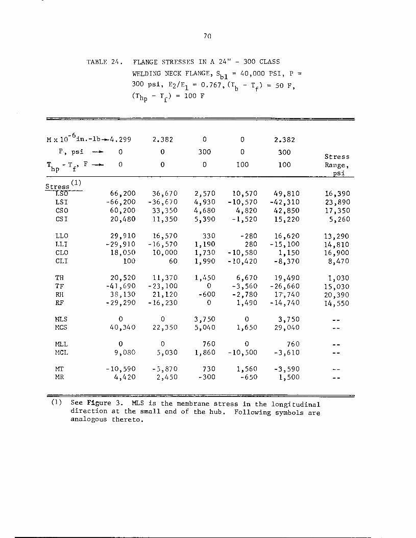
70
TABLE 24. FLANGE STRESSES IN A 24" - 300 CLASS
WELDING NECK FLANGE, Sbl = 40,000 PSI, P
300 psi, E2/E1 = 0.767, (Tfe - T ) = 50 F,(T hp - v = 100 F
MxlO" 6in.--lb-*.4.299 2.382 0 0 2.382
P, psi -*• 0 0 300 0 300Stress
T, - T_, Fhp f
—*- 0 0 0 100 100 Range,psi
StressLSO
(1)
66,200 36,670 2,570 10,570 49,810 16,390LSI -66,200 -36,670 4,930 -10,570 -42,310 23,890CSO 60,200 33,350 4,680 4,820 42,850 17,350CSI 20,480 11,350 5,390 -1,520 15,220 5,260
LLO 29,910 16,570 330 -280 16,620 13,290LLI -29,910 -16,570 1,190 280 -15,100 14,810CLO 18,050 10,000 1,730 -10,580 1,150 16,900CLI 100 60 1,990 -10,420 -8,370 8,470
TH 20,520 11,370 1,450 6,670 19,490 1,030TF -41,690 -23,100 0 -3,560 -26,660 15,030RH 38,130 21,120 -600 -2,780 17,740 20,390RF -29,290 -16,230 0 1,490 -14,740 14,550
MLS 0 0 3,750 0 3,750 — —
MCS 40,340 22,350 5,040 1,650 29,040--
MLL 0 0 760 0 760 _ _
MCL 9,080 5,030 1,860 -10,500 -3,610 --
MT -10,590 -5,870 730 1,560 -3,590 - _
MR 4,420 2,450 -300 -650 1,500
(1) See Figure 3. MLS is the membrane stress in the longitudinaldirection at the small end of the hub. Following symbols areanalogous thereto.
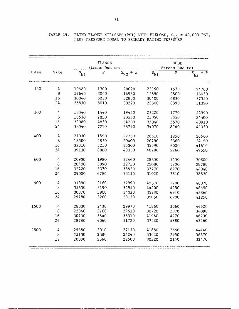
71
TABLE 25. BLIND FLANGE STRESSES(PSI) WITH PRELOAD, Sbl = 40,000 PSI,PLUS PRESSURE EQUAL TO PRIMARY RATING PRESSURE
FLANGE CODE
Size
Stress Due to: Stress Due to:
Class Sbl P Sb2 + P Sbl PSb2 + P
150 4 19680 1300 20620 23190 1570 24760
8 12640 3040 14930 12550 3500 16050
16 30040 6030 32880 30400 6830 37320
24 25850 8010 30270 22500 8890 31390
300 4 18340 1440 19450 23220 1770 24990
8 18530 2850 20530 21050 3350 24400
16 32080 4830 34700 35340 5570 40910
24 33040 7210 36790 34070 8260 42330
400 4 21030 1590 22260 26610 1950 28560
8 18300 2850 20400 20790 3360 24150
16 32310 5210 35300 35590 6020 41610
24 39130 8080 43350 40290 9260 49550
600 4 20930 1980 22460 28350 2450 30800
8 20490 3090 22750 25080 3700 28780
16 32420 5370 35520 37770 6270 44040
24 29000 6780 33110 31020 7810 38830
900 4 31390 2160 32990 45370 2700 48070
8 32630 3490 34940 44400 4250 48650
16 30370 5900 34030 35930 6910 42860
24 29780 5260 33130 35050 6200 41250
1500 4 28030 2430 29970 41860 3060 44920
8 22340 2760 24610 30720 3370 34090
16 30730 3540 33310 41960 4270 46230
24 28780 4060 31720 37380 4880 42260
2500 4 25380 2010 27150 41880 2560 44440
8 22130 2380 24240 33420 2950 36370
12 20380 2360 22500 30320 2150 32470

72
The stress due to the bolt load and the sum of stresses due
to bolt load and pressure are appropriately categorized, in the authors'
opinion, as primary plus secondary stresses. A fatigue analysis leads to
the same conclusion reached for welding neck and straight hub flanges; i.e.,
for any credible set of operating conditions, B16.5 flanges should be
acceptable under the analysis requirements of NB-3650.
Effect of Pipe Bending Moment on Flange Stresses
In the preceding we have discussed operating conditions of
pressure and temperature effects. We will now discuss the effect of
pipe bending moments. In the preceding section on "Flange Stress
Limits of NB-3647, Allowable Pipe Bending Stresses at Rated Pressures",
we reached the conclusion that several widely used flanges could not
take any pipe bending moment, as judged by the NB-3647 criteria.
We will now consider appropriate limits to pipe bending
stresses, as limited by flange stresses. We will confine the dis
cussion to welding neck flanges because the limitations will be less
severe for straight hub flanges.
First, we note that at the junction of the flange to the pipe,
we obtain a stress of S ,. The effect of this load on changing the bolt
load is included in the computer program FLANGE; see a., in Equation (9)
and Table 5. The change in bolt load is theoretically significant but
the change in moment acting on the flange ring is small. Because flange
stresses are proportional to the moment acting on the flange ring, we
can say, to a good first approximation, that the flange stresses are
changed, as a result of applying a pipe bending moment, only in the hub
region; i.e., the stress range due to pipe bending moment range is simply
S , at the small end of the hub and S (g /g ) at the large end of the
hub. Considering the pipe bending moment cycle separately, we would only
consider the range of S , at the small end of the hub because thepb
stress range at the large end of the hub is obviously smaller. However,
73
in combining the bolt tightening/untightening cycle, and other operating
conditions with the pipe bending moment, the stress at the large end of
the hub might be controlling.
As a simple example, let us consider the 24" - 400 lb
welding neck flanged joint with S (range) limited by the bolts to
24,200 psi (See Table 17, column headed Bolt Stress, Program FLANGE).
Let us assume an operating history consisting of a bolt tightening, 100
cycles of S = 24,200 psi, and then bolt untightening. Table 18 shows
that the stress due to the preload, S,, = 40,000 psi, is equal to 79,020
psi, and is located at the small end of the hub. Accordingly, the usage
fraction involves the cycles
Number
Stress Range of Cycles
79,020 + 24,200 1
24,200 99
Assuming the flange material is SA-105 and that S = 20,600 psi (at 400 F)m
for the one major stress cycle, and S = 17,300 psi (at 700 F) for the 99
minor stress cycles, then the value of K (See NB-3228.3) is 2.35 for the major
cycle and 1.00 for the minor cycles. At this point, we must select a suitable
stress concentration factor. In general, we are analyzing the flanges and
not the girth butt weld between flange and pipe. However, for this example,
we will use the K-index of 1.8 given in Table NB-3683.2-1 for an "as welded"
girth butt weld. The value of S is then (79,020 + 24,200) x 2.35 x 1.8/2 =
218,310 psi for the one major cycle and 24,200 x 1.8/2 = 21,780 psi for
the 99 minor cycles. Turning to the Code Figure 1-9.1, we find that the
usage fraction is 1/80 for the major cycle; 99/60,000 for the minor
cycles. The total usage fraction is 0.014 hence, the postulated
combination of bolt tightening/untightening with intervening pipe bending
stress cycles can be repeated about 70 times in-so-far as flange stress
limits are concerned.

74
There are no test data to check the fatigue life due to bolt
tightening/untightening cycles. However, there are some test data given
in Appendix A for fatigue under cyclic pipe bending moments. The test
data indicate 3,400,000 cycles to failure for an S , range of 24,200 psi.
This, divided by 20 to correspond to the Code factor of safety of 20
on cycles, checks adequately with the Code procedure design life cycles
of 60,000.
Summary of Results on Flange Stresses
Calculations were made on a representative sampling of B16.5
flanged joints with:
(a) Rated pressure of ANSI B16.5-1968 for carbon steel
flange material; specifically SA-105 for checking
Code flange stress criteria
(b) Gasket O.D. = raised face O.D.
Gasket I.D. = pipe O.D.
m = 2.75, y = 3,700
(c) Bolt material: SA-193 Grade B7
From the results of these calculations, the following conclusions
can be drawn.
(1) The number of acceptable flanges with zero pipe bending moment is
tabulated below. A total number of 27 flanges of each type were
checked.
Code Temp.
Reference F
NB-3647.1 100
VIII-Div. 1 100
NB-3647.1 700
Number AceeptableStraightWelding
Neck
24
13
24
Hub
27
10
27
Blind
23
4
27
Number Nnt AcceptableWelding StraightNeck Hub Blind
3
14
3
0
17
0
4
23
0

75
(2) The allowable pressures by Code criteria, for those flanges
which are not acceptable at the rating pressure, are
erratic and in 8 flanged joints the allowable pressure is
zero. In view of the satisfactory operating history of
B16.5 flanged joints, it is apparent that the Code flange
stress criteria are not accurate for evaluating the pressure
capacity of B16.5 flanged joints.
(3) Allowable bending stresses in pipe attached to flanged
joints, as evaluated by NB-3647.1 flange stress criteria,
is zero for 3 flanged joints and very low for most of the
flanged joints.
(4) Basic theory calculations of flange stresses with 40,000
psi initial bolt load give high calculated stresses. An ex
planation of why the flanges are capable of withstanding
the bolt loads without gross yielding is presented.
(5) Basic theory calculations indicate that the stresses at
points of maximum stress due to bolt load are changed
only slightly by internal pressure; they may either
decrease or increase.
(6) Application of the NB-3650 type of analysis indicates
that, with 40,000 psi initial bolt stress, the fatigue
limits of the Code will be satisfied for any ordinarily
anticipated loading history.
76
6. RECOMMENDATIONS
Specific recommended Code changes are included herein as Appendix C.
In the following, changes contained in Appendix C are cited, followed by
the reason for the recommendation. It is necessary to have the Code at
hand to follow the discussion.
(1) Change NB-3651.2 to read:
NB-3651.2 Piping Products for Which Stress Indices Are Not Available.
For analysis of flanged joints, see NB-3658. For other piping products for
which stress indices are not available, see NB-3680.
Reason: We wish to inform the Code user that, while stress indices are not
given for flanged joints, special guidance is given in NB-3658.
(2) Change NB-3647.1 to read:
NB-3647.1 Flanged Joints.
(a) Flanged joints manufactured in accordance with the standards listed in
Table NB-3132-1, as limited by NB-3612.1, shall be considered as meeting
the requirements of NB-3640.
(b) Flanged joints not included in Table NB-3132-1 shall be designed in
accordance with Article XI - 3000, including the use of the appropriate
allowable stress given in Table 1-7.
Reason: This subparagraph is written so that it gives requirements for
pressure design; analogous to the Code format for all other piping products.
The Code user either:
(a) Selects a standard flange with appropriate pressure-
temperature ratings, or

77
(b) Designs the flanges for the design pressure by the Code
procedure.
The authors considered deletion of the proposed NB-3647.1(b) because non
standard flanges are rarely used in piping systems. The proposed NB-3647.1(b)
is not the same as the present NB-3647.1, even for P =0, because no excep
tion is made to Article XI-3000. Article XI-3000 uses stresses for Class 2
or Class 3 components and the stress limits are different (in some cases,
more conservative) than the present NB-3647.1(d).
(3) Add a New Paragraph NB-3658 to Read as Follows:
NB-3658 Analysis of Flanged Joints
Flanged joints using flanges, bolting, and gaskets as specified in
ANSI B16.5 (1968) and using a bolt material having an S - value at 100 F notm
less than 20,000 psi may be analyzed in accordance with the following rules
or in accordance with NB-3200. Other flanged joints shall be analyzed in
accordance with NB-3200.
Reason: Analysis requirements for flanged joints, as the Code is presently
written, are scattered about and difficult to interpret. The present
NB-3647.1, by the last sentence in NB-3647.1(b), invokes operating condition
evaluations which, for all other piping products, are handled under NB-3650.
The analysis of the flanges (not the bolts or the weld between flanges and
pipe) under NB-3650 seems to follow the path:
NB-3651 - No stress indices, go to NB-3680
NB-3680 - go to (d) - Experimental or theoretical analysis
Theoretical analysis - go to NB-3200
Experimental analysis - go to Appendix II
The proposed NB-3658 is intended to gather in one place the rather
specialized requirements for the analysis of flanged joints and to give
relatively simple and explicit rules for ANSI B16.5 flanged joints.
78
The first sentence was motivated by:
(a) What few flanged joints are used in Class 1 piping systems are likely
to be ANSI B16.5. Accordingly, giving rules for ANSI B16.5 will
probably cover most needs. However, they are not mandatory; NB-3200
can be used. The reason for restriction to bolt material with Sm
20,000 psi at 100 F is given in Appendix B.
(b) The data given in this report gives a basis for the proposed analysis
rules for ANSI B16.5. However, that basis does not necessarily apply
to other standard flanges that are or may later be included in
Table NB-3691-1, nor to flanges designed in accordance with Article XI-
3000.
NB-3658.1 Design, Normal and Upset Conditions
(a) Bolting. The bolting shall meet the requirements of NB-3232. In addition,
the limitations given by Equations (15) and (16) shall be met.
Mfg < 3125 (Sy/36)C ^ , (15)
Reason: The first sentence retains the present Code requirement now contained
in NB-3647.1. Specific reference is made to NB-3232 (rather than NB-3230)
because it covers normal conditions; NB-3233 simply says: "Use NB-3232 for
upset conditions". NB-3234 and NB-3235 are not referred to because the proposed
NB-3658.2 and NB-3658.3 cover the emergency and faulted conditions. The quite
extensive portion of this report on "Bolt Areas and Bolt Stresses" indicates
that the rules of NB-3232 are readily met if the bolts are SA-193 Grade B7.
From this standpoint, the first sentence could be deleted and the authors
would have no strong objection to doing so. The sentence was left in on the
basis that (a) the report evaluations do not cover all conceivable combina
tions of loadings, and (b) the bolting evaluation is fairly simple to carryout using a computer program such as FLANGE.

79
The development of Equation (15) is described in Appendix B, where
it is identified as Equation (B5). As discussed in Appendix B, Equation (15)
(a) is conservative with respect to available test on joint leakage,
(b) is a good approximation of the moment capability (as limited by
joint leakage) as determined by the computer program FLANGE with
an assumed bolt prestress of 40,000 psi,
(c) except for the 150 class, gives permissible moments essentially equal
to or higher than permitted by the rules in the present NB-3647.1,
(d) tends to discourage the use of the larger sizes of 150 class joints by
giving a small permissible moment.
where
M, = bending or torsional moment (considered separately)
applied to the joint due to weight, thermal expansion
of the piping, sustained anchor movements, relief
valve steady-state thrust, and other sustained
mechanical loads, in.-lb. If cold springing is used,
the moment may be reduced to the extent permitted by
NB-3672.8.
S = yield strength (ksi) of flange material at design
temperature (Table 1-2.2). The value of (S /36) shally
not be taken as greater than unity.
C = diameter of bolt circle, in.
A^ = total cross-sectional area of bolts at root of thread or
section of least diameter under stress, sq. in.
Mfd < 6250 (S /36) C A^ , (16)
Mfd - bending or torsional moment (considered separately) as
defined for Mf but including dynamic loadings, in.-lb.

80
Reason: The present NB-3647.1 relates P to both M and F = axial load.eq
This is the only piping product for which NB-3600 requires consideration
of axial loads. Until such time as axial loads are required to be con
sidered for all piping products, it is recommended that F be deleted from
consideration for flanged joints.
In the present, NB-3647.1, M is defined as:
M = bending moment applied to the joint due to weight
and thermal expansion of the piping, in.-lb.
Several questions arise concerning the definition.
(Ql) Why is relief valve thrust not included? The only application of
flanged joints in Class 1 piping known to the authors involves
relief valves.
(Q2) What credit, if any, can be taken for "cold springing"
(Q3) Why are torsional moments ignored?
(Q4) Why are dynamic loads (e.g., earthquake) ignored?
(Q5) Why is moment loading due to use of the flanged joint to "pull out"
fabrication mismatch ignored? In many commercial piping installations,
this may be the major source of moment loading on a flanged joint.
The authors' answers to these questions, and resulting recommendations are:
(Al) The "steady state" relief valve thrust should be included. See
also (A4)
(A2) Credit should be given for "cold springing" to the extent provided
in NB-3672.8
(A3) As discussed in Appendix B, torsional moments should not be ignored,
but they can be considered separately from bending moments and
the limit used for bending moments can also be used for torsional
moments.
(A4) Presumably the reason dynamic loads were ignored in the definition
of M is that they are of short-time duration and flanged-joint
leakage would be small during that time. Further, provided these
dynamic loads did not break or yield the bolts or flanges, the

81
flanged joint would be "tight" after the dynamic loading stopped.
However, there is nothing to guard against a very high dynamic
moment which might cause the bolts or flanges to yield or crack.
To provide a control for this, Equation (16) is included in the
proposed NB-3658.1, to place a limit on static-plus-dynamic moments.
The basis of Equation (16) is discussed in Appendix B [identified
as Equation (B6)] along with calculated pipe bending stresses resulting
from its use. While the equation is quite conservative, it nevertheless
permits relatively high dynamic stresses in the attached pipe for all
except the 150 class..
(A5) The quality controls for nuclear power plant piping system fabrication
should be sufficient to prevent fabrication misalignment pull-out
being a major source of moment loading on flanged joints.
(b) Flanges. Flanges of ANSI B16.5 flanged joints meeting the requirements
of NB-3612 are not required to be analyzed under NB-3650. However,
the pipe-to-flange welds shall meet the requirements of NB-3652, NB-3653,
and NB-3654, using appropriate stress indices from Table NB-3683.2-1.
Reason: The first sentence is based on one of the major aspects developed
in the report, i.e., that flange stresses, other than at the pipe-to-flange
weld area, are due to the bolt prestress load and not due to either pressure
or moment loads. This applies even for blind flanges with pressure loading;
see Table 25. Accordingly, there is no point in checking the flange stresses
under NB-3650 unless we go to the extreme of checking for bolt tightening/
untightening cycles. As discussed in the text, any credible number of bolt
tightening/untightening cycles gives only a small fatigue usage fraction.
However, as pointed out by the second sentence, the stresses at
the welds may vary significantly due to pressure, moments and thermal gradients
and hence, should be analyzed just as any other weld in the piping system
should be analyzed.
82
NB-3658.2 Emergency Conditions
(a) The pressure shall not exceed 1.5 times the design pressure.
(b) The limitation given by Equation (17) shall be met.
Mfd <[11250 Ab -(tt/16) dJ Pfd] C(S /36) , (17)where
D^ = outside diameter of raised face, in.
pfd = pressure (psi) during the emergency condition concurrentwith M£,.
rd
Mfd' C' Sy' the lim±tation on (S /36) and A^ are defined inNB-3658.1(a).
(c) Pipe-to-flange welds shall be evaluated by Equation (9) of NB-3652,using a stress limit of 2.25 S .
m
Reason: The pressure limit of 1.5 times the design pressure is analogous to
the limit of NB-3655.1. As discussed in Appendix B, the pressure limit is
deemed appropriate provided Equation (17) is also invoked. The basis for
Equation (17) is discussed in Appendix B, [identified as Equation (B7)]
along with numerical examples of its application. The proposed NB-3658.2(c)is the same as the present NB-3655.2.
NB-3658.3 Faulted Conditions
(a) The pressure shall not exceed 2.0 times the design pressure.
(b) The limitation given by Equation (17) of NB-3658.2(b) shall be
met, where Pfd and Mfd are pressures (psi) and moments (in.-lb)occurring concurrently during the faulted condition.
83
(c) Pipe-to-flange welds shall be evaluated by Equation (9) of NB-3652,
using a stress limit of 3.0 S .° m
Reason: The pressure limit of 2.0 times the design pressure is analogous
to the limit of F-1360(a). As discussed in Appendix B, the pressure limit
is deemed appropriate provided Equation (17) is also invoked. It may be
noted that NB-3656, Consideration of Faulted Conditions, refers the Code
user to Appendix F of the Code. However, the guidance given by Appendix F
for flanged joints is nebulous, at best, and hence, it was deemed appropriate
to supply specific rules for flanged joints under faulted conditions. The
Code user may use Appendix F, through the pathway of NB-3200 rules.
NB-3658.4 Testing Conditions. Analysis for Testing Conditions is not required.
Reason: At present, NB-3657, "Testing Conditions", refers the Code user
to NB-3226. The requirements of NB-3226 are not relevant to flanged-joints.
In testing flanged joints, one normally is looking for leakage at the gasket;
if the leakage is deemed excessive, the normal next step is to increase
the preload on the bolts. There is a control on maximum preload through
the requirements in NB-3232.1 that average bolt stress shall not exceed
two times the allowable bolt stress. Accordingly, analysis for testing
conditions is not deemed to be needed.
(1) NC-3651, Add:
(c) For analysis of flanged joints, see NC-3658.

84
(2) NC-3671.1, Delete Period After "NC-3647" and Add:
and NC-3658.
Reason: We wish to inform the Code user that special guidance for flanged
joints is given in NC-3658. It may be noted that we jump from NC-3652
to NC-3658. This is to provide consistency in numbering with the NB portion
of the Code.
(3) NC-3673.5(a)
Change equation numbers: (12) to (15) and (13) to (16),
(4) NC-3673.5(b)
Change "Formulas (12) and (13)" to "Equations (15) and (16)".
Reason: Editorial to introduce new equations and their numbers in NC-3658.
(5) Change NC-3647.1 to Read:
NC-3647.1 Flanged Joints.
(a) Flanged joints manufactured in accordance with the standards listed
in accordance with the standards listed in Table NC-3132-1, as
limited by NC-3612.1, shall be considered as meeting the requirements
of NC-3640.

85
(b) Flanged joints not included in Table NC-3132-1 shall be designed in
accordance with Article XI - 3000.
Reason: To give requirements for pressure design under NC-3640, "Pressure
Design of Piping Products", and eliminate those requirements which should
go under NC-3650, "Analysis of Piping Systems".
(6) Add a New Paragraph NC-3658 to Read as Follows:
NC-3658 Analysis of Flanged Joints
Flanged joints using flanges, bolting, and gaskets as specified in
ANSI B16.5 (1968) and using a bolt material having an S - value at 100 F
not less than 20,000 psi may be analyzed in accordance with the following
rules or in accordance with NB-3200. Other flanged joints shall be analyzed
in accordance with NB-3200. If the NB-3200 analysis is used, allowable
stresses from Table 1-7 and 1-8 shall be used in place of S .m
Reason: To gather into one place the rather specialized requirements for the
analysis of flanged joints and to give relatively simple and explicit rules
for ANSI B16.5 flanged joints.
A question arises as to what analysis should be made for flanged
joints not conforming to the first sentence. While most flanged joints are
B16.5 and SA-193 Grade B7 bolts are commonly used, in Class 2 piping systems
there may be other types of joints; particularly in sizes larger than 24". The
present rules in NC-3650 are not relevant to any kind of flanged joint. Code
case 1744 provides some assistance but it is limited to maximum pressures
of 100 psi and maximum temperatures of 200 F. For lack of a better
available solution, the last two sentences were included which, in
principle, will give guidance for any type of flanged joint.

86
NC-3658.1 Design, Normal and Upset Conditions
(a) The limitations given by Equations (12) and (13) shall be met.
where
where
Mfs
S =
C
\
M 1 3125 (S /36) C A^ (12)
bending or torsional moment (considered separately)
applied to the joint due to weight, thermal expansion
of the piping, sustained anchor movements, relief valve
steady-state thrust and other sustained mechanical loads,
in.-lb. If cold springing is used, the moment may be
reduced to the extent permitted by NC-3673.5.
yield strength (ksi) of flange material at design tempera
ture (Table 1-2.2). The value of (S /36) shall not be
taken as greater than unity,
diameter of bolt circle, in.
total cross-sectional area of bolts at root of thread or
section of least diameter under stress, sq. in.
Mfd £ 6250 (S /36) C A^ (13)
M,. = bending or torsional moment (considered separately) as
defined for M but including dynamic loadings, in.-lb,
Reason: At present, NC-3600 does not define or use normal conditions,
upset conditions, emergency conditions or faulted conditions. However,
work by Code committees is in advanced stages in which these terms (or,
more likely, their equivalents called "design limits") will be used for
both Class 2 and Class 3 components. The recommendations have been
written on the assumption that the revised rules will be implemented
in the near future.

87
It may be noted that a requirement analogous to that in NB-3658.1
of "The bolting shall meet the requirements of NB-3232" is not imposed.
This is deemed to be consistent with Class-2 design philosophy in which
cyclic stresses, other than those due to cyclic moments, are not considered.
Otherwise, NC-3658.1 is essentially identical to NB-3658.1 and the same
reasons apply. It may be noted that the allowable bolt stresses in Class 2
are lower than in Class 1. However, this is not relevant to the problem.
The relevant aspect concerns the assumed preload stress of 40,000 psi and
the assumption is deemed to be equally valid for Class 1 and Class 2.
(b) Flanges. Flanges of ANSI B16.5 flanged joints meeting the require
ments of NC-3612.1 are not required to be analyzed under NC-3650.
However, the pipe-to-flange welds shall meet the requirements of
NC-3652. using appropriate stress intensification factors from
Figure NC-3673.2(b)-l.
Reason: See those cited under NB-3658.1(b). The second sentence is
appropriate for Class 2 piping, which uses stress intensification factors.
NC-3658.2 Emergency Conditions
(a) The pressure shall not exceed 1.5 times the design pressure.
(b) The limitation given by Equation (14) shall be met.
Mfd <[11250 Ah -(tt/16) D^ Pfd] C(S /36) , (14)where
D = outside diameter of raised face, in.
Pfd = Pressure (Psi) during the emergency condition concurrentwith M,.,.
rd
Mfd' C' Sy' the limitation on (S /36) and A^ are defined in
NC-3658.1(a).

88
(c) Pipe-to-flange welds shall be evaluated by Equation (9) of NC-3652,
using a stress limit of 1.8 S, .h
Reason: The pressure limit in (a) and the stress limit in (c) conform to
the general limitations for emergency conditions being established
for Class 2 piping. The reason for (b) is discussed under NB-3658.2(b).
NC-3658.3 Faulted Conditions
(a) The pressure shall not exceed 2.0 times the design pressure.
(b) The limitation given by Equation (14) shall be met, where V.,f d
and Mf are pressures (psi) and moments (in.-lb) occurring
concurrently during the faulted condition.
(c) Pipe-to-flange welds shall be evaluated by Equation (9) of NC-3652,
using a stress limit of 2.4 S, .h
Reason: The pressure limit in (a) and stress limit in (c) conform to the
general limitations for faulted conditions being established for Class 2
piping. The reason for (b) is discussed under NB-3658.3(b).
NC-3658.4 Testing Conditions. Analysis for Testing Conditions is not required.
Reason: Analysis for testing conditions is not addressed in the present
NC-3600. Testing conditions will be identified in the rules under develop
ment but, as presently drafted, analysis for testing conditions is not
required.
89
ND-3600
It is recommended that ND-3600 be changed as shown for NC-3600;
changing NC to ND in all places where NC occurs. In ND-3673.5, the present
equation numbers (9) and (10) are to be changed to (15) and (16) in two
places. Do not change the phrase: "using Equations (9) and (10) (ND-3650)."
Reason: For the purpose of these recommendations, ND-3600 (Class 3 piping)
is identical to NC-3600 (Class 2 piping). The only exception is equation
numbers which, if the recommendations are followed, will make ND-3600 and
NC-3600 identical in this respect.

90
7. ACKNOWLEDGEMENT
The author wishes to thank the members of Task Group 1 of the
Pressure Vessel Research Committee, Subcommittee on Piping, Pumps and
Valves, and the members of the ASME Boiler and Pressure Vessel Code
Committee, Subgroup on Piping (SGD) (SCIII), for their review and valuable
suggestions. The authors wish to express their appreciation to Mr. E. B. Branch,
Mr. J. T. McKeon, Mr. F. M. O'Hara, Jr. and Mr. F. E. Vinson for their many
valuable comments and suggestions.

91
8. REFERENCES
(1) ASME Boiler and Pressure Vessel Code, Section III, Nuclear PowerPlant Components. Published by the American Society of MechanicalEngineers, 345 E. 45 Street, New York, New York 10017. (1974 Ed.)
(2) American National Standards Institute, "Steel Pipe Flanges andFlanged Fittings", USAS B16.5-1968. Published by the AmericanSociety of Mechanical Engineers, 345 E. 45th Street, New York,New York 10017.
(3) Rodabaugh, O'Hara, and Moore, "Computer Program for the Analysis ofFlanged Joints with Ring-Type Gaskets", ORNL-5035, Oak Ridge NationalLaboratory, Oak Ridge, Tennessee.
(4) Roberts, I., "Gaskets and Bolted Joints", ASME J. of AppliedMechanics, 1950.
(5) Petrie, E.C., "The Ring Joint, Its Relative Merit and Application",Heating, Piping and Air Conditioning", Vol. 9, No. 4, April, 1937.
(6) Maney, G., "Bolt Stress Measurement by Electrical Strain Gages",Fasteners, Vol. 2, No. 1.
(7) Rossheim, Gebhardt, and Oliver, "Tests of Heat-Exchanger Flanges",Trans. ASME, May, 1938.
(8) Murray, N.W., and Stuart, D.G., "Behavior of Large Taper HubFlanges", Inst. Mechanical Engineers, Pressure Vessel Research,1961.
(9) George, Rodabaugh, and Holt, "Performance of 6061-T6 AluminumFlanged Pipe Assemblies under Hydrostatic Pressure", ASME PaperNo. 56-PET-19.
(10) Tube Turns Report No. 8.010a, "Bending Tests on 4" - 300 lb ASAWelding Neck and Lap Joint Flanges", September 8, 1953.
(11) Gough, H.J., First Report of the Pipe Flanges Research Committee",Engineering, February 28, 1936.
(12) Tube Turns Report No. 2.024, "Tests on 3" 150 lb ASA WeldingNeck and Slip-on Flanges", June 11, 1955.
(13) Tube Turns Report No. 2.030, "Hydrostatic Test of a 4 - 900 lbWelding Neck Flanged Joint", May 2, 1955.

92
8. REFERENCES (Continued)
(14) Tube Turns Report No. 2.036, "Effect of Flange Material YieldStrength on the Pressure Capacity of a Flanged Joint", April 25,1958.
(15) Tube Turns Report No. 2.033d, "Tests of Taper Face Welding NeckFlanges Under Gas and Hydrostatic Internal Pressure with andwithout External Bending Moment", May 21, 1958.
(16) Markl, A.R.C., and George, H.H., "Fatigue Tests on FlangedAssemblies", ASME Transactions, 1950.
(17) Kalnins, A., "Analysis of Shells of Revolution Subjected toSymmetrical and Non-Symmetrical Loads", ASME Journal of AppliedMechanics, September, 1964.
(18) Blick, R.G., "Bending Moments and Leakage at Flanged Joints",Petroleum Refiner, 1950.
(19) Design of Piping Systems, The M.W. Kellogg Co., 2nd Edition,1956, Published by John Wiley & Sons, New York, N.Y.
(20) API Std. 605, "Large Diameter Carbon Steel Flanges", Publishedby the American Petroleum Institute, Division of Refining, 1271Avenue of the Americas, New York, N.Y. 10020.

APPENDIX A
TEST DATA ON FLANGED JOINTS
TABLE OF CONTENTS
Page
INTRODUCTION A-l
TEST DATA ON DISPLACEMENTS, STRAINS, AND STRESSES A-l
Tests on Heat Exchanger Flanged Joint with a Metal Gasket. . . . A-2
Change in Bolt Length with Pressure A-4
Flange Rotation due to Bolt Load A-10
Flange Rotation due to Pressure A-14
Tests on a Large Flanged Joint with O-Ring Gasket A-l7
Change in Bolt Stress with Pressure A-23
Flange Rotation due to Pressure A-24
Flange Stresses due to Pressure A-26
Tests on ANSI B16.5 Flanged Joints with Asbestos Gaskets,Bolt Stress Change with Pressure A-30
LEAKAGE PRESSURE TESTS A-33
TEST DATA WITH PIPE BENDING MOMENT A^i5

INTRODUCTION
The text of this report gives results of calculations using
the computer program FLANGE . The theoretical basis for this program
is given in Reference (3). Essentially, it is based on a shell
and plate discontinuity analysis and, as applied to actual flanged
joints, cannot be expected to be very accurate; particularly with re
spect to flange stresses. There are larger uncertainties involved in
the selection of load application lines; i.e., "effective gasket
diameters" and "effective bolt circle diameters". For any but flat
metal gaskets, there are major uncertainties concerning the "effective
modulus of elasticity" of the gasket.
In this Appendix, available test data are presented which
give some indication of the effects of the variables mentioned above.
The data are for internal pressure loading and, to a limited extent, for
internal pressure combined with a pipe bending moment. No test data
are available on thermal gradients in flanged joints.
TEST DATA ON DISPLACEMENTS, STRAINS, AND STRESSES
Because flanged joints are statically redundant structures,
their theoretical analysis involves the rotations of the flanges due
to the loads (bolt load, pressure, thermal gradients) and the axial
strains in the bolts. Three sets of data which can be used to check
the validity of the theory as used in the computer program FLANGE are
discussed in this section.
* All calculations made with FLANGE used the hub-to-ring boundary
condition represented by the option IBOND = 2 in FLANGE. Thisoption, in general, gives better correlation with test datathan does the hub-to-ring boundary condition used in the Codemethod (IBOND = 0 option in FLANGE).
A-2
(7)(1) Tests on Heat Exchanger Flanges with Metal Gasket
These data are closest to "ideal" for the purpose of
checking the theory because a narrow metal gasket was used;
thus reducing uncertainties concerning the "effective gasket
diameter" and modulus of elasticity of the gasket material.
/•ON
(2) Tests on Large Flanges with O-Ring Gasket
While a flanged joint without bolt preload is a statically
determinate structure, these tests involved a moderate preload-
hence, the interaction effects can be evaluated for low pressures.
Further, at higher pressures, flange rotations and flange stresses
for the statically-determinant loads can be compared with theoretical
predictions. The data include the best available measurements of
stresses in a welding neck flange. In the statically redundant
portion of the tests, an effective gasket diameter must be selected;
this is difficult because the raised face is very wide compared to
the radial distance between the center of the raised face and the
bolt circle.
(3) Tests on ANSI B16.5 Flanges With Asbestos Gaskets ^
The leakage aspect of these tests are discussed later under
"Leakage Pressure Tests" and details of the gaskets are given
thereunder. In this section, the change of bolt stress with
pressure is discussed. The major uncertainty in these tests
consists of selection of an appropriate effective modulus of
elasticity for the gaskets under the test conditions.
Tests on Heat Exchanger Flanged Joint with a Metal Gasket
Reference (7) gives test data for the flanged joint shown in
Figure Al. Experimental results consist of:

FLANGE C-l
7C.L.of Knuckle(Radiuson Head\ -4"-
16
3ii»16
2i"-28-1 Diam Holes
VM///Mi
i
4 l».
f274
25"ID 26I"CLof'4 284"BC 24"|D 304/bDGasket
Tonoue and GosketDetails of All Flanges.Gasket Material -Soft Iron
FIGURE Al. DETAILS OF FLANGED JOINT, REFERENCE (7).
FLANGE C-2
C.L. of Knuckle
Radius on Head4"
>i
oo

A-4
(1) Plot of bolt elongation versus internal pressure. Elongation
was measured with calipers. Considerable scatter exists in
the test data, as might be expected using this method.
(2) Flange rotation due to internal pressure.
(3) Flange rotation due to bolt load.
The printout from the computer program FLANGE for the flanged
joint is shown in Table Al. The input data to FLANGE (printed out
on the first page of Table Al) is based on:
(a) Dimensions as shown in Figure Al.
(b) Modulus of elasticity = 30 x 10 psi for flanges, bolts, and gasket
(c) Bolt area = 28 (bolts) x 0.419 (root area per bolt) = 11.732 sq. in.
(d) Pressure = 1,000 psi, Moment =hQ x Afo x 40,000 psi = 439,950 in.-lb,Wl = initial bolt load = 40,000 A^ = 469,280 lb.
The somewhat arbitrary aspect of the input consists of appropriate
modeling of the plate between the flanges so as to incorporate the
elastic response of the plate. This was done by using gasket dimensions
of XG0 = 27.750" ,XGI = 26.000" and Gm = actual mean gasket diameter =26.875"; gasket thickness (VO) of 1.500". The gasket thickness is equalto the plate thickness, gasket O.D. = plate O.D. and gasket I.D. arbitrarilyset at 26" as representing that part of the plate which deforms elasticallyunder load.
Change in Bolt Length with Pressure
The test data are shown in Figure A2, along with the calculatedresult obtained by the following equation.
6 = (W1-W2) P_ A = -6b 1000 A F 5,W5 X iU *
b

TABLE Al: OUTPUT FROM COMPUTER PROGRAM FOR HEAT EXCHANGER FLANGED JOINT,FIGURE Al (SHEET 1 OF 4).
FLANGE
O.O., AFLANGE FLANGE PIPE HUB AT HUB BOLT PRESSURE.
,. ,. „ I«°"8 THICK. ,T HALL,GO BASE.G1 LENGTH.H CIRCLE.C P33.75000 25.00000 2.50000 0.42200 0.62500 0.81250 28.75000 1000.000
MOMENT COEFF. "F DELTA MOO. OF MEAN GASKETTHERMAL EX". ELASTICITY DIAMETER
i.3S9? 05 6.0000-06 1.000D-03 3.0000 07 2.6880 01
I TYPE ibond
2
I CODE
0
MATE
3
FLANGE FLANGE FLANGE PIPE HUB AT0.0..A I.O..R THICK.,T MALL,GO BASE.Gl30.'5000 2*.25000 1.50000 0.42200 1.00000
MOMENT COEFF. OF DELTA Mnn. OF MEAN GASKETTHE=»AL EXP. ELASTICITY DIAMETER
4.3990 05 6.000D-06 l.OOOD-03 3.0000 07 2.6880 01
HUB BOLT PRESSURE,LENGTH,H CIRCLE.C P2.75000 28.75000 1000.000
bsize
8. 7*000-01VO
1.50000 00Hi
4.6928D 05
YB
3.00000 0 7YG
3.00000 07TF
0.0
E8
6.00003-06
EG
6.00000-06TFP
0.0
ITYPE
TB
0.0
TG
0.0
YF2
3.0303 0 07
IBOND
2
ICODE
0
XGO
2.77500 01
FACE0.0
YFP23.00000 07
MATE
4
XGI
2.60000 01PBE
0.0YB2
3.00000 07
FLANGE JOINT BOLT LOAD CHANGE DUE TO APPLIED LOADS, INTEGER TO INTEGER PAIR
FLANGE JOINT SIDE ONE (PRIMEO QUANTITIES*
CFHG- 7.390 20-09 QPHG- 1.58100-06 OTHG- 1.52740-05 X8 = 2.50000 01YM . 3.00000 07 YF2 - 3.0000D 07 EF - 6.00000-06
AB
1.17320 01
YG2
3.0000D 0 7
GO- 4.2200D-01 TH
FLANGE JOINT SIDE TWO <UN°RIMED QUANTITIES)
QF^- 8.36030-09 QPHG* 1.56720-06 QTHG= 2.04480-05 XB = 2.42500 01YM - 3.00000 07 YF2 > 3.00000 07 EF - 6.0000D-06
BOLT ING
BOLT LENGTH* 6.37500 00 BOLT AREA* 1.17320 01 BOLT CIRCLE" 2.8750D 01YB - 3.0000D 07 Y92 - 3.0000D 07 EB
GASKET
VO * 1.50000 00 XGOYG » 3.00000 07
6.3000D-06
2.77500 01 XGI « 2.6000D 01YG2 » 3.00000 07 EG » 6.0000D-06
GO" 4.2200D-01 TH
2.5 000D 00
1.5 0000 00
>I
On
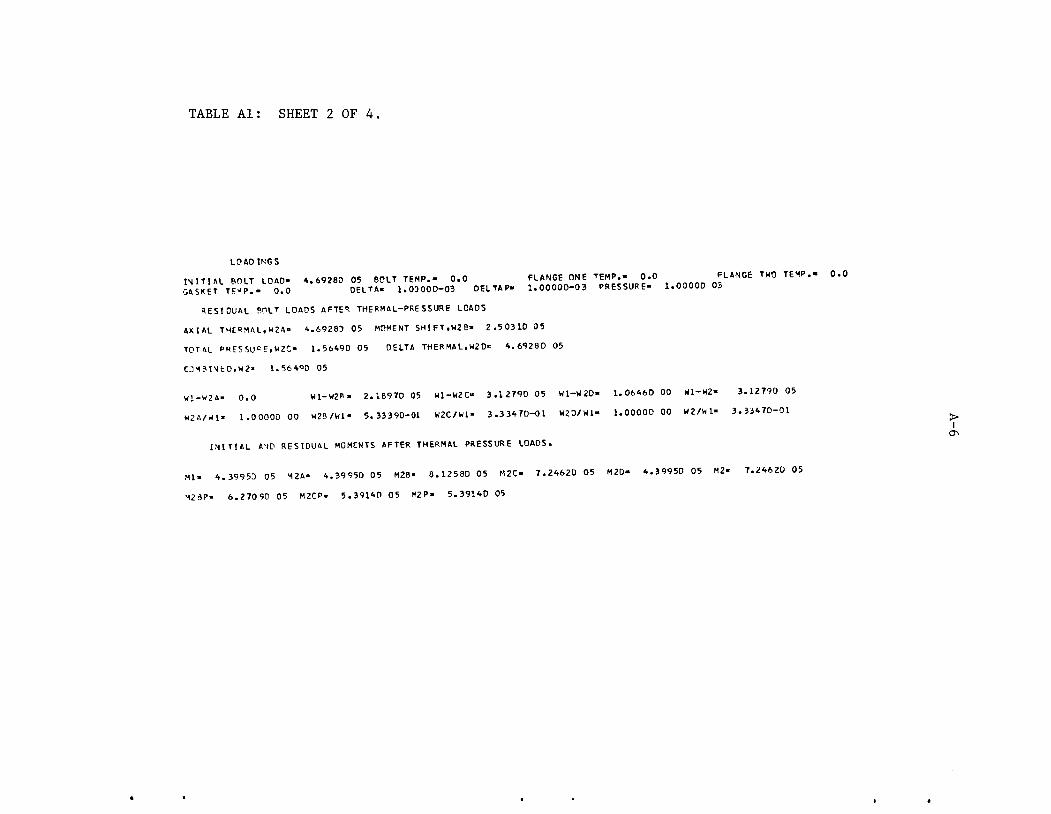
TABLE Al: SHEET 2 OF 4.
LOADINGS
INITIAL BOLT LOAD- 4.6928D 05 BOLT TEMP.- 0.0 FLANGE ONE TEMP.- 0.0 FLANGE TWO TEMP.- 0.0GASKET TE-P.- 0.0 DELTA- 1.03000-03 DELTAP- 1.00000-03 PRESSURE- 1.00000 03
RESIOUAL BOLT LOADS AFTER THERMAL-PRESSURE LOADS
AXIAL THERMAL,W2A- 4.69283 05 MOMENT SHIFT, W2 B- 2.50310 05
TOTAL PRESSURE,H2C- 1.5649D 05 OELTA THERMAL,W2D-= 4.69280 05
CJMBINfcD,W2» 1.564°D 05
W1-W2A. 0.0 W1-W2P- 2.1897D 05 W1-W2C- 3.12790 05 W1-W20- 1.06460 00 W1-W2- 3.12790 05W2A/-1- 1.00000 00 H2B/W1- 5.3339D-01 W2C/W1- 3.3347D-01 W20/W1- 1.00000 00 W2/W1- 3.33470-01 >
I
INITIAL AND RESIOUAL MOMENTS AFTER THERMAL PRESSURE LOADS.
Ml- 4.39950 05 M2A- 4.39950 05 M2B- 8.12580 05 M2C- 7.24620 05 M2D> 4.39950 05 M2- 7.2462D 05
M2SP- 6.2709D 05 M2CP. 5.39140 05 M2P- 5.39140 05
ON

TABLE Al: SHEET 3 OF 4.
TAPERED HUB FLANGE
CALCULATIONS FOR MOMENT LOADING
SLSO- 2.9370D04 SLSI- -2.93700 04 SCSO- 2.12820 04 SCSI- 3.660,0 03SLLO- 2.64! 8D04 SLLI- -2.64180 04 SCLO- 1.59180 04 SCLI- 6.72180 0!SrH. 9.07420 03 »,.,.„«.„ SRH. 3.60570 03 SRF- -2.62B4D 03
ZG. -3.29369-03 ZC- -6. 54450-03 QFHG- 3.25090-03 YO- 5 19630-03 Y, ,„CALCULATIONS FOR PCESSURE LOADING 33°2°"°3
SLSO. ,.,„„, 0, SLSr. |>9a83B04 s:so. uwiom scs[_ ^^SLLO. 4.12520 03 SLLI- 1.58750 04 SC LO- 1.28820 04 SCLI- 1.64070 04STH. 1.09720 04 STF. 9.6346D 02 SRH- -2.23950 03 SRF- -1.96650 02 ^
Z». -1.63S5D-03 ZC- -3.21750-03 OFHG- 15Binnna v„ , ***OVULATIONS FOR WBMTwe L0AD[NG l-58l0°03 V°" 6'̂ 20-03 - '"
SLSO- 3.26B1O-03 SLSI- -3.26.UD-03 SCSO- -7.96350-0 2SLLO. -4.68090-02 SLLI- 4.6S09D-02 SC LO- -1. 3070D-0 1 SCLI- -1.0 2620-01STH. 5.968tP.02 STF. .3.7010r,.02 SRH. .1>21820.02 SRp, 7>5540D_03
^i;::::::::::::;::::::Ir;:;:r-:;:;T:;™;r;::^:;I;:;:-»•-»SLSO. 4.97300 04 SLSL -2.0109D 04 SCSO- 4.56920 04 SCSI- 2.47400 04SLLO. 3.64990 04 SLLL -1.64990 04 SC LO- 3.2388D 04 SCL,- 1.64890 04STH. 2.2092D 04 s~F. -,.tM« 04 SRH- 2.17910 03 SRF- -3.41760 03-—03 ZC -1.1238D-02 OFHG- 5.56490-03 YO- L28220-02 Yl- 3.93270-03 THETA- -6.07300-03
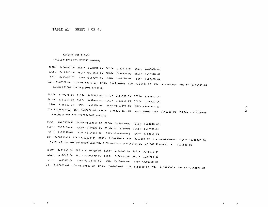
TABLE Al: SHEET 4 OF 4.
TAPERED HUB FLANGE
CALCULATIONS FOR MOMENT LOADING
SLSO. 1.2404D 04 SLSI. -1.24040 04 SCSO- 1.4247D 04 SCSI- 6.8043D 03SLLO- 2.18560 04 SLLI- -2.16560 04 SC LO- 7.5797D 03 SCLI- -5.5337D 03STH- 5.33610 03 STF. -1 .5339D 04 SRH- 1.43770 04 SRF- -1.20450 04
ZC -4.83180-03 ZC -8.50950-03 OFHG- 3.67770-03 Y0- 4.25400-03 V*. 4.13450-04 THETA- -3.43500-03CALCULATIONS FOR PRESSURE LOAOING
SLSO. 1.90240 04 SLSI. 9.70810 03 SCSO- 2.61490 04 SCSI- 2.33540 04SILO. 5.210 90 03 SLLI. 6.9141D03 SCLO- 9.98060 03 SCLI- 1.04920 04STH. 7.86720 03 STF. ,..68„0 03 SRH= _..833,0 Q3 SRp= _3.93800 Q2 >
ZC -2.235!O-03 ZC -3.85230-03 OFHG- 1.56720-03 Y0= 8.26180-03 VI- 3.4020D-03 THETA- -1.78100-03 »CALCULATIONS FOR TFMPERATURE LOADING
SLSO. 8.6395D-02 SLSI. -8.63950-02 SCSO- 3.56500-02 SCSI- -1.61870-02SLLO. 9.O9.3O-03 SLL !• -9.99630-03 S: LO- -1 . 127 10-0 1 SCL I- -1. 187 10-01STH. 6.00910-02 STF. -2.05160-02 SRH- -1.40080-0 2 SRF= 4.78240-03
ZC -2.98150-08 ZC -5.02630-0- QFHG. 2.0448D-08 YO- 3.93300-09 Y1- -4.67650-08 THETA- -2.32380-08CALCJLATIONS FOR COMBINED LOAOING, M2 OR M2 P FCR ITYPE-1 OR 2. W2 FOR ITYPE-3, - 7.24620 05
SLSO= 3.94540 04 SL SI- -1.072 2D 04 SCSO- 4.96140 04 SCSI- 3.4561D04SLLO= 4.123 80 0* SLL 1= -2.9083D 04 SCLO- 2.24650 04 SCLI= 1.37710 03STH. 1.66560 04 STF. -2.3575D 04 SRH. 2.18460 04 SRF= -2.0233D 04
ZC -1.02430-02 ZC -1.7868D-02 QFHG- 7.6245D-03 YO. 1.52680-02 Y1- 4.0829D-03 THETA- -7.43870-03

700
A-9
o TEST DATA
THEORY BASED ON W
THEORY BASED ON W,
8 16 24 32
Decrease in Bolt Length , .0001 in.
FIGURE A2. COMPARISON OF THEORETICAL AND MEASURED CHANGEIN BOLT LENGTH WITH PRESSURE, REFERENCE (7 )TEST DATA.
40
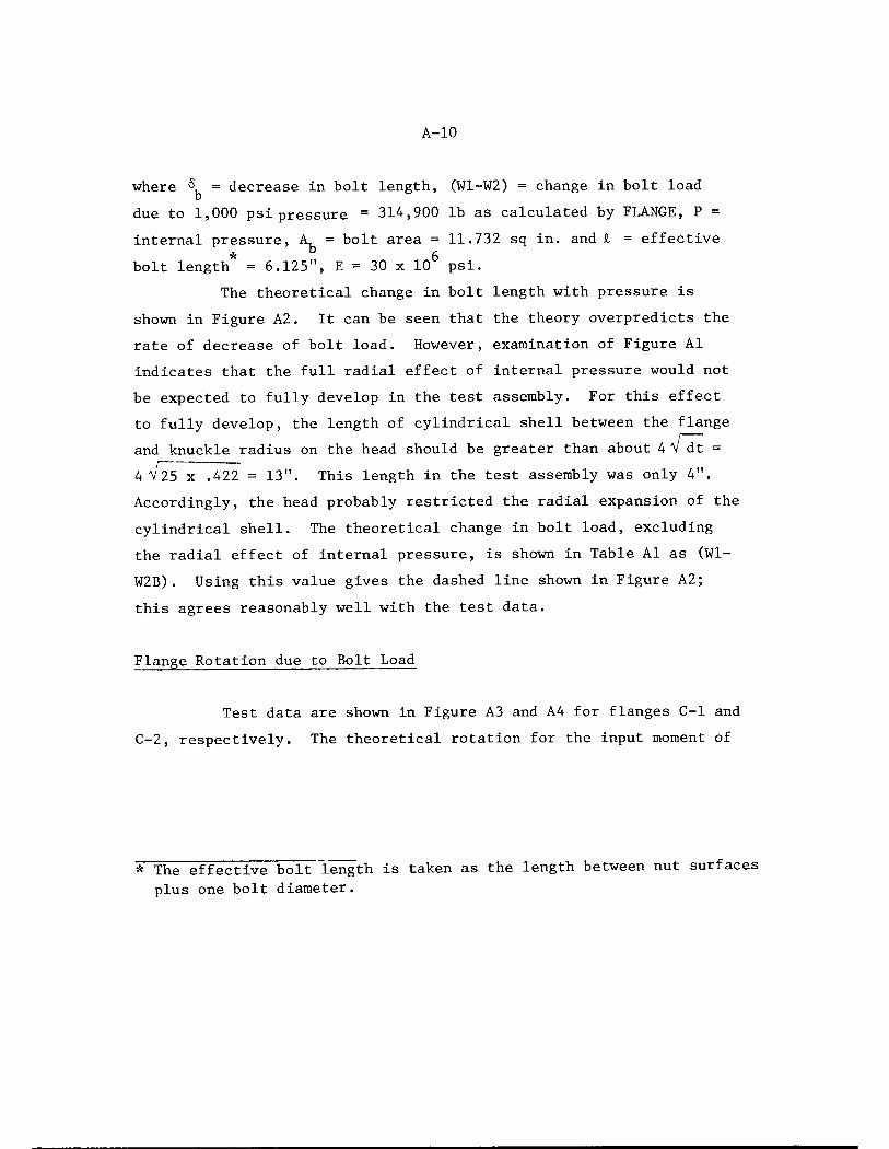
A-10
where "?, = decrease in bolt length, (W1-W2) = change in bolt loadb
due to 1,000 psi pressure = 314,900 lb as calculated by FLANGE, P =
internal pressure, A^ = bolt area = 11.732 sq in. and £ = effective
bolt length* = 6.125", E= 30 x 106 psi.The theoretical change in bolt length with pressure is
shown in Figure A2. It can be seen that the theory overpredicts the
rate of decrease of bolt load. However, examination of Figure Al
indicates that the full radial effect of internal pressure would not
be expected to fully develop in the test assembly. For this effect
to fully develop, the length of cylindrical shell between the flange
and knuckle radius on the head should be greater than about 4V dt =
4V25 x .422 = 13". This length in the test assembly was only 4".
Accordingly, the head probably restricted the radial expansion of the
cylindrical shell. The theoretical change in bolt load, excluding
the radial effect of internal pressure, is shown in Table Al as (Wl-
W2B). Using this value gives the dashed line shown in Figure A2;
this agrees reasonably well with the test data.
Flange Rotation due to Bolt Load
Test data are shown in Figure A3 and A4 for flanges C-l and
C-2, respectively. The theoretical rotation for the input moment of
* The effective bolt length is taken as the length between nut surfacesplus one bolt diameter.

1000
800
oO 600o
T3OO
-J
o00
400
200
A-ll
o TEST DATA
THEORY
FLANGE c-i
16 24
Flange Rotation , minutes32
FIGURE A3. COMPARISON OF THEORETICAL AND MEASUREDFLANGE ROTATIONS DUE TO BOLT LOAD, FLANGE C-1REFERENCE (7) TEST DATA
40

ooo
•ooo
1000
800
600
A-12
o TEST DATA
THEORY
o 400GO
200FLANGE c-2
16 24
Flange Rotation , minutes
32
FIGURE A4. COMPARISON OF THEORETICAL AND MEASUREDFLANGE ROTATIONS DUE TO BOLT LOAD, FLANGE C-2REFERENCE (7) TEST DATA
40

A-13
439,900 in.-lb is shown in Table Al as THETA = 3.5115 x 10 and 3.4345 x 10*
for flanges CI and C2, respectively. With M = WhG, where hQ = 0.9375" for
this joint:
M^G
3.5115 x 10 3 x 0.9375 W radians439,900
7.484 x 10 3W radians = 2.573 x 10 W minutes
for flange C-1, and similarly for flange C-2
-3= 2.516 x 10 W minutes.
These theoretical lines are shown in Figures A3 and A4. The test data
and theory agree reasonably well at low loads. At higher loads, the
test data indicate that yielding of the flanges might have occurred.
The calculated stresses are high enough to indicate the possibility
of such yielding.
* The negative signs in Table Al for "THETA" is the sign convention usedin the basic theory indicating rotation in the direction of moment dueto bolt load^
** Shifting of the bolt load inward or gasket effective diameter outwardwould also produce a non-linear effect; however, the curvature of thetest data is opposite to what would occur from this effect.

A-14
The tests were apparently run by increasing the bolt load in steps and,
at each step increasing the pressure in steps; perhaps as high as 650
psi with 850,000 lb bolt load. Under these loads, the maximum stresses
are:
Flange C-1, SLSO (Longitudinal, small end of hub, outside
SLSO =^3gq0 x850,000 x .9375 +13,qqq x650 = 62,140 psi
Flange C-2, SLLO (longitudinal, large end of hub, outside
surface)
SLLO =,2h8oL x 850,000 x .9375 +|^|^ x 650 = 42,980 psi.439,900 1,000
The materials used for the flanges and attached shell are not described
in Reference (7). Presumably they were carbon steel with a yield strength
in the range of 30,000 to 50,000 psi.
Flange Rotation Due to Pressure
Test data are shown in Figure A5 and A6 for flanges C-1 and
C-2, respectively. The theoretical increase in flange rotation due to
internal pressure is given by:
AG =ep_ Ap + em AM APP M P
From Table Al, we obtain:
pi e /pFlange p'6 /Mm
(Al)
AM/P
1.7703 x 10 3 3.5115 x 10 3 (5.3867-4.3995) x 1Q5C-1 1000 439900 1000
1.7810 x 10 3 3.4354 x 10 3 (7.2416-4.3995) x 105C-2 100n 439900 1000

Q.
a>i—
3
to0>
CD
C
700
600
500
400
300
200
100
A-15
o TEST DATA o o
THEORY
2.5
FLANGE c-i
5 7.5
Flange Rotation, minutes
FIGUREA5. COMPARISON OF THEORETICAL AND MEASURED FLANGE
ROTATIONS DUE TO INTERNAL PRESSURE, FLANGE C-1,REFERENCE (7) TEST DATA
10

toQ.
700
500 -
£ 4003totoa>
a
£ 300
200 -
A-16
o TEST DATA
THEORY
FLANGE c-2
2.5 5 7.5
Flange Rotation, minutes
FIGURE A6. COMPARISON OF THEORETICAL AND MEASUREDFLANGE ROTATIONS DUE TO INTERNAL PRESSURE,FLANGE C-2, REFERENCE (7) TEST DATA
10

A-17
Using these values in Equation (Al) gives:
For Flange C-1
AO = (1.770 x 10~6 + 7.982 x 10_9 x 98.72)AP = 2.558 x 10~6 AP radians
= 0.00879 AP minutes
For Flange C-2
A6 = (1.781 x 10"6 + 7.810 x 10_9 x 284.2) AP = 4.006 x 10_6 AP rad
= 0.0138 AP minutes
These lines are shown in Figures A5 and A6. The theory is in good
agreement with the test data for flange C-1, with again some test data
evidence of yielding at high pressure (actually, high pressure combined
with high bolt load) . The theory over predicts the flange rotation of
flange C-2. The test data do not indicate yielding of flange C-2.
Tests on a Large Flanged Joint with O-Ring Gasket
Reference (8) gives test data for the flanged joint shown
in Figure A7. Experimental data consist of:
(1) Plot of bolt stresses versus internal pressure. Bolt stresses
were determined by strain gages on the bolts.
(2) Flange rotation due to internal pressure.
(3) Longitudinal stress on outer surface of hub due to internal pressure.
lans

A-18
180 —l^g" Bolts
FIGURE A7. DIMENSIONS OF REFERENCE (8) FLANGES,IDENTICAL PAIR USED IN JOINT.
180.0625" <t>
177.9375" £
180.6875"
185"
137.9375"
190.9375"

A-19
Printout from the computer program FLANGE for the flanged joint
is shown in Table A2. The input data to FLANGE (printed out on the first
page of Table A2) is based on:
(a) Dimensions as shown in Figure A7.
(b) Modulus of elasticity = 30 x 10 for flanges, bolts, and
"gasket".
The elastomeric 0-ring gasket is assumed to act only as a
seal, hence, the gasket is simply the 1/8" raised face.
(c) Bolt area = 253.4 sq in.
(d) Pressure = 100 psi, Moment = h x A, x S = 7,920,000 in.-lb
Wl = initial bolt load = A^ x S = 5,392,352 lb.
The somewhat arbitrary aspect of the input consists of
appropriate modeling of the "effective gasket diameter". Looking
at Figure A7, and considering the rotation of the flanges, one would
intuitively expect that most of the load between flanges would be
carried by a relatively narrow annular ring of the raised face near
the outside of the raised face. To investigate this, the following
effective gasket diameters were assumed.
Effective Gasket
in.
Gasket Initial Moment,
Diameter, in. O.D. I.D. in.-lb
185
184
183
182
180.7
1.46875
1.96875
2.46875
2.96875
3.61875
186.4
185.4
184.4
183.4
182.1
183.6
182.6
181.6
180.6
179.3
7,920,00010,616,00013,312,00016,009,00019,514,000

TABLE A2. OUTPUT FROM COMPUTER PROGRAM FOR LARGE FLANGED JOINT, FIGURE A7.
FLANGE FLANGE FLANGE PIPE HUB AT HUB BOLT PRESSURE,O.D..A I.D..B THICK.,T WALL.GO BASE.G1 LENGTH,H CIRCLE.C P
193.93750 177.93750 5.00000 1.06250 2.75000 10.50000 187.93750 100.000
MOMENT COEFF. OF DELTA MOD. OF MEAN GASKET
THERMAL EXP. ELASTICITY DIAMETER7.9230 06 6.0000-06 1.0000-03 3.0000 07 1.850D 02
I TYPE
BSIZE
1.50000 0 0
VO
1. 25000-0 1
Wl
5. 39240 06
Y9
3.0000D 07
YG
3.00000 07
TF
0.0
E8
6.00000-06
EG
6.0000D-06
TFP
0.0
TB
0.0
TG
0.0
YF2
3.03000 07
IBOND
2
ICODE MATE
0 2
XGO
1.8640D 02
FACE
0.0
YFP2
3.00000 07
XGI
1.63600 02
PBE
0.0
YB2
3. OOOOD 07
FL4NGE JOINT BOLT LOAD CHANGE DUE TO APPLIED LOADS, IDENTICAL PAIR
FLANGE JOINT SIDE ONE (PRIMED QUANTITIES)
AB
2.53*00 02
Y3 2
3.00000 07
2FHG- 5.64260-10 QPHG- 1.41000-05 QTHG- 5.9924D-05 XB - 1.7794D 02YM = 3. OOOOD 07 YF2 • 3. OOOOD 07 EF » 6.00000-06
GO- 1.0625D 00 TH
FLANGE JOINT SIDE TWO (UNPRIMEO QUANTITIES)
3FHG- 5.64260-10 QPHG- 1.41000-05 QTHG= 5.99240-05 XB - 1.77940 02y « 3.00300 07 YF2 » 3.OOOOD 07 EF - 6.0000D-06
fOLT ING
BOLT LENGTH* 1.16250 01 BOLT ARFA- 2.53400 02 BOLT CIRCLE" 1.87940 02
Ye » 3.00000 07 YB2 « 3.OOOOD 07 EB ' 6.00000-06
CASK ET
VO » 1.2 5000-01 XGO
YG - 3.00300 07
1.86400 02 XGI » 1.83600 02
Y32 » 3.30000 07 EG = 6.00000-06
GO" 1.06250 00 TH
5.000CD 03
5.OOOOD 00
>I
O
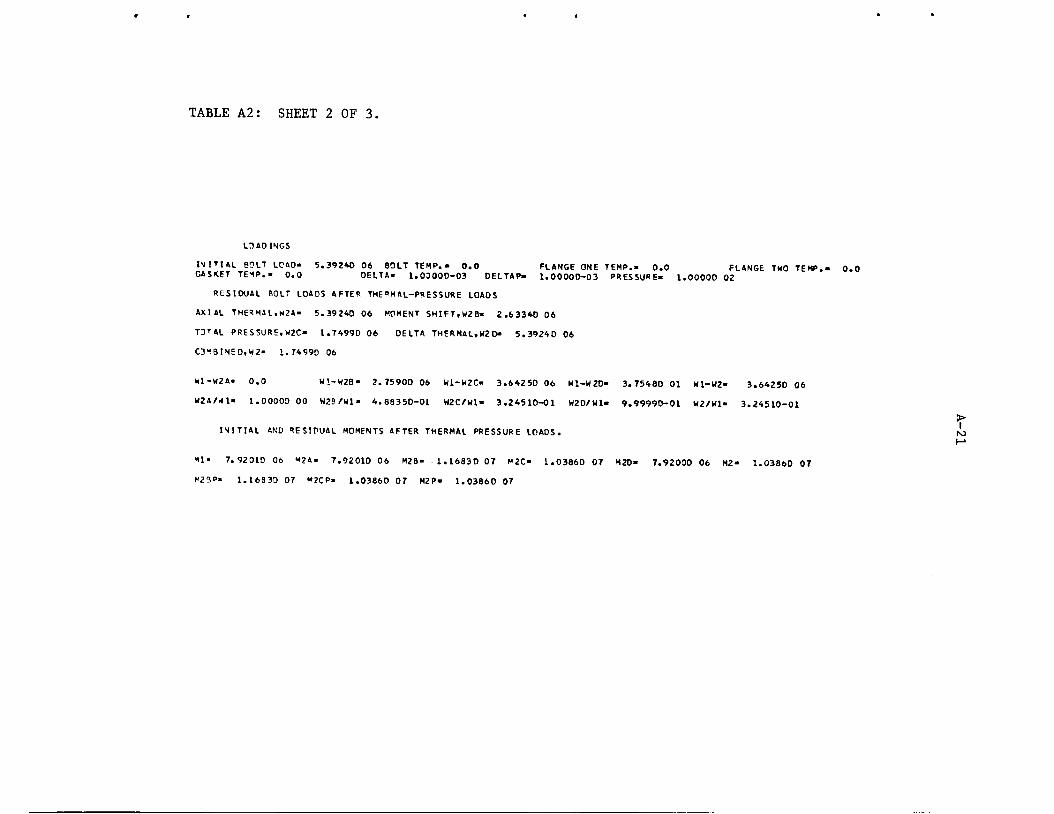
TABLE A2: SHEET 2 OF 3.
LOADINGS
INITIAL BOLT LOAD- 5.392*0 06 BOLT TEMP.- 0.0 FLANGE ONE TEMP.. 0.0 FLANGE TWO TEMP.- 0.0CASKET TEMP.- 0.0 DELTA- 1.03000-03 OELTAP- 1.00000-03 PRESSURE- 1.OOOOD 02
RESIOUAL BOLT LOAOS AFTER THERMAL-PRESSURE LOADS
AXIAL THERMAL,W2A- 5.39240 06 MOMENT SHIFT,W2B- 2.6334D 06
TDTal PRESSURE,W2C- 1.74990 06 DELTA THERMAL, W2 D- 5.3924D 06
CD*!8!NE0,W2» 1.7499D 06
W1-W2A- 0.0 W1-W2B- 2.75900 06 W1-W2C- 3.64250 06 W1-W20- 3.75480 01 WI-W2- 3.64250 06
W2A/rfl» 1.OOOOD 00 W2B/WI- 4.88350-01 W2C/W1- 3.24510-01 W20/W1- 9.99990-01 W2/W1- 3.24510-01
INITIAL ANO RESIDUAL MOMENTS AFTER THERMAL PRESSURE LOAOS. N>
HI- 7.92010 06 M2A- 7.9201D 06 M2B- 1.16830 07 M2C- 1.03860 07 M20- 7.9200D 06 M2- 1.03860 07
K29P- 1.1683D 07 M2CP- 1.03860 07 M2P- 1.0386D 07

TABLE A2: SHEET 3 OF 3.
TAP ERED HUB FLANGE
CALCULATIONS FOR MOMENT LOAOING
SLSO- 9.0539D 03 SLSI- -9.0589D 03 SCSO- 8.0258D 03 SCSI- 2.5905D 03
SLLO- 8.37670 03 SLLI- -8.37670 03 SCLO- 1.8688D 03 SCLI- -3.15720 03
STH. 3.76960 02 STF- -6.«5340 03 SRH- 3.40360 03 SRF- -2.96880 03
ZC -1.0644^-02 ZC -1.51130-02 OFHG- 4.4690D-03 YO- 1.57420-02 Yl- -1.91040-03 THETA- -2.9766D-03CALCULATIONS FOR PRESSURE LOADING
SLSO- 5.65000 03 SLSI- 2.72350 03 SCSO- 7.48920 03 SCSI- 6.61130 03
SLLO- 1.51360 03 SLLI- 1.7166D 03 SCLO- 2.85770 03 SCLI- 2.9171D 03
STH. 2.35240 03 S'F- 7.4I79D 02 SRH- -1.6560D 02 SRF- -5.2220D 01
Z3- -3.42110-03 ZC- -4.83100-03 QFHG- 1.41000-03 YO- 1.71840-02 Yl- 7.12370-03 THETA- -9.7548D-04t̂o
CALCULATIONS FOR TEMPERATURE LOAOING N>
SLSO- 1.03220-01 SLSI- -1.03220-01 S: SO- 3.80430-02 SCSI- -2.38900-02
SLLO- 1.20450-02 SLLI- -1.20450-02 SCLO- -1.1217D-01 SCLI- -1.19400-01
STH. 6.2S07O-02 STF. -5.56480-03 SRH- -4.42700-03 SRF- 3.91740-04
Z5- -1.45390-07 ZC -2.05320-07 OFHG- 5.99240-03 YO- 2.09870-08 Yl- -3.43380-07 THETA- -4.14580-08CALCULATES FOR COMBINED LOAOING,M2 OR M2P FOR ITYPE-1 OR 2. W2 FOR ITYPE-3, - 1.03860 07
SLSO- 1.75290 04 SLSI- -9.1556D 03 SCSO- 1.80140 04 SCSI- 1.0008D 04
SLLO- 1.25030 04 SLLI* -9.2679D 03 SCLO- 5.30820 03 SCLI- -1.22310 03
STH. 2.846 70 03 STF= -T.8517D 03 SRH- 4.29750 03 SRF- -3.94520 03
ZC -1.73790-02 ZC -2.4650D-02 QFHG- 7.27020-03 YO- 3.78260-02 Y1= 4.6182D-03 THETA- -4.8788D-03
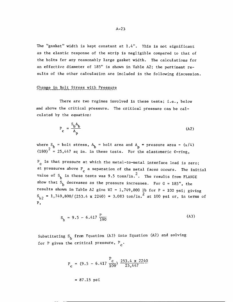
A-23
The "gasket" width is kept constant at 1.4". This is not significant
as the elastic response of the strip is negligible compared to that of
the bolts for any reasonably large gasket width. The calculations for
an effective diameter of 185" is shown in Table A2; the pertinent re
sults of the other calculation are included in the following discussion.
Change in Bolt Stress with Pressure
There are two regimes involved in these tests; i.e., below
and above the critical pressure. The critical pressure can be cal
culated by the equation:
pc =-£* ^>p
where S, = bolt stress, A, = bolt area and A = pressure area = (tt/4)
(180) = 25,447 sq in. in these tests. For the elastomeric 0-ring,
Pc is that pressure at which the metal-to-metal interface load is zero;
at pressures above P a separation of the metal faces occurs. The initialc 2
value of Sfe in these tests was 9.5 tons/in. . The results from FLANGEshow that Sfe decreases as the pressure increases. For G = 185", theresults shown in Table A2 give W2 = 1,749,800 lb for P = 100 psi; givingSb2 =1,749,800/(253.4 x2240) =3.083 ton/in.2 at 100 psi or, in terms ofP,
q = q s - 6 417 -— (A3)bb 100
Substituting S, from Equation (A3) into Equation (A2) and solving
for P gives the critical pressure, P .
/„ r c #-.-, ?c x253.4 x 2240Pc - (9.5 - 6.417 m) 25>447
= 87.15 psi

A-24
These relationships are shown graphically in Figure A8 for the various
assumed values of G . The values of G , P , and S, at P are:e e c b c
Ge» V S. at P ,b c'
in. psi ton/in.2
185 87.15 3.907
184 97.13 4.354
183 110.51 4.954
182 125.75 5.638
180.7 147.07 6.593
It can be seen in Figure A8 that, as might intuitively be expected,
the effective gasket diameter is somewhat smaller than the raised
face outside diameter; an effective gasket diameter of about 183"
agrees best with the test data.
Above P , the increase in bolt stress is given by Equation
(A2)
Flange Rotation Due to Pressure
Below P , the theoretical increase in flange rotation duec
to pressure is given by Equation (Al). For G = 185", Table A2 gives
6 /P = 9.7548 x 10_4/100 and 6 /M = 2.9766 x 10_3/7.92 x 106. TableP m
A2 also shows M = 1.0386 x 10 for AP = 100 psi, hence, AM =
M -M = 1.0386 x 10⁷ - 0.792 x 10⁷ for P = 100 psi.Accordingly, Equation (Al) gives:
AG = 9.7548 x 10~6 Ap + 3.758 x 10_10(1.0386 - 0.7920) x 10? AP_100
= 1.9022 x 10"5 AP radians
= 0.0654 AP minutes (A4)
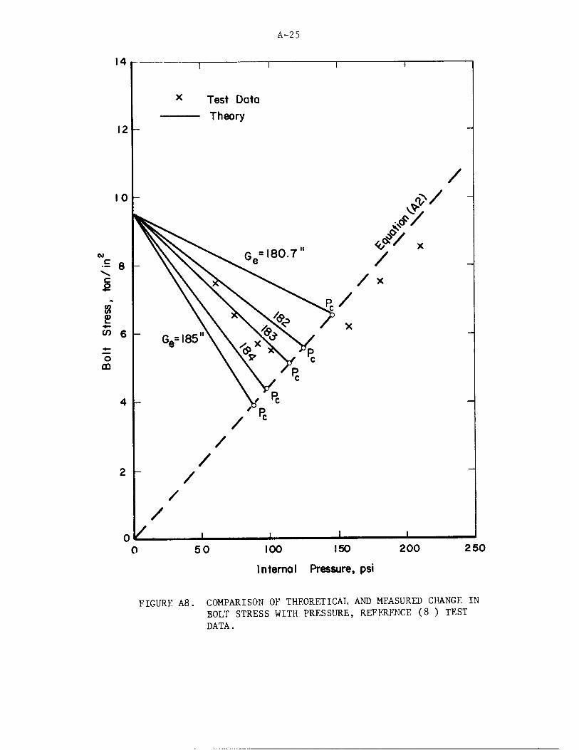
A-25
50 100 150 200 250
Internal Pressure, psi
FIGURE A8. COMPARISON OF THEORETICAL AND MFASURED CHANGE INBOLT STRESS WITH PRESSURE, REFERENCE (8 ) TESTDATA.

A-26
Equation (A4) is shown in Figure A9, along with theoretical lines for
G = 185, 184, 183, 182 and 180.7 inches. These lines terminate at
P . Above P , the rotation is given by Equation (Al) but AM is obtained
by the equation:
AM = AphpAP (A5)
where
II = moment arm to midsurface of attached shell
- [C - (B + go)] II
= [187.9375 - (177.9375 + 1.0625)] /2 = 4.469"
2With A = 25,447 in. , Equation (A5) gives
AM = 113.722AP in.-lb
Equation (Al) then gives
A0 = (9.75 x 10 6+ 3.758 x 10 10 x 113,722)Ap, radians
= 5.2492 x 10 5AP radians
= 0.1805 AP minutes.
The value ofA6 /AP does not depend upon the choice of G but the value
of P does. The complete curves are shown in Figure A9. As in Figure
A8 for bolt stress change, Figure A9 indicates that an effective
gasket diameter of about 183" agrees best with the test data.
Flange Stresses Due to Pressure
Test data are given (only) for longitudinal stresses on the
outside surface of the hub. These are stated to be stresses obtained
above P and are for a pressure change of 100 psi. The theoretical
value of stress is obtained by:
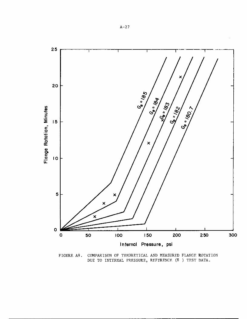
50
A-27
100 150 200
Internal Pressure, psi
250
FIGURE A9. COMPARISON OF THEORETICAL AND MEASURED FLANGE ROTATION
DUE TO INTERNAL PRESSURE, REFERENCE (8 ) TEST DATA.
300
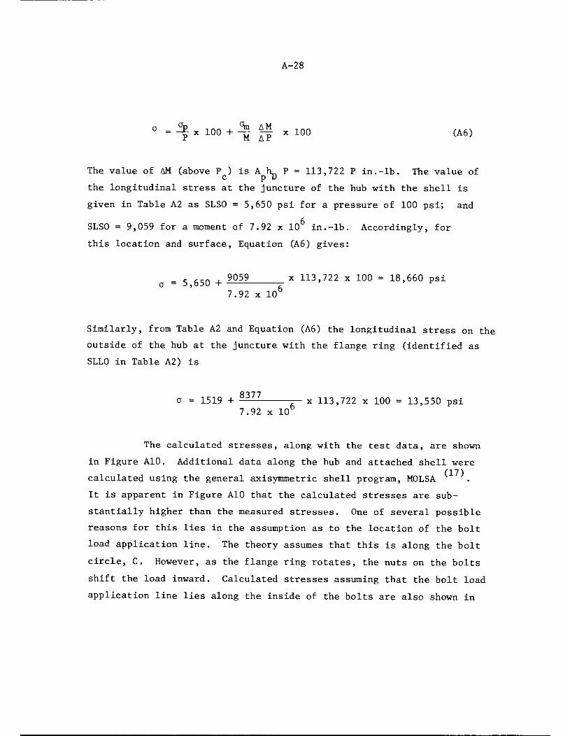
A-28
° =-i- x100 +^ *-f x100 (A6)
The value of AM (above P ) is A L P = 113,722 P in.-lb. The value of
the longitudinal stress at the juncture of the hub with the shell is
given in Table A2 as SLSO = 5,650 psi for a pressure of 100 psi; and
SLSO = 9,059 for a moment of 7.92 x 10 in.-lb. Accordingly, for
this location and surface, Equation (A6) gives:
- ~n . 9059 x 113,722 x 100 = 18,660 psia = 5,650 H 7- ' v
7.92 x 10
Similarly, from Table A2 and Equation (A6) the longitudinal stress on the
outside of the hub at the juncture with the flange ring (identified as
SLLO in Table A2) is
8377a = 1519 + -^^ j- x 113,722 x 100 = 13,550 psi7.92 x 10
The calculated stresses, along with the test data, are shown
in Figure A10. Additional data along the hub and attached shell were(17)
calculated using the general axisymmetric shell program, MOLSA
It is apparent in Figure A10 that the calculated stresses are sub
stantially higher than the measured stresses. One of several possible
reasons for this lies in the assumption as to the location of the bolt
load application line. The theory assumes that this is along the bolt
circle, C. However, as the flange ring rotates, the nuts on the bolts
shift the load inward. Calculated stresses assuming that the bolt load
application line lies along the inside of the bolts are also shown in
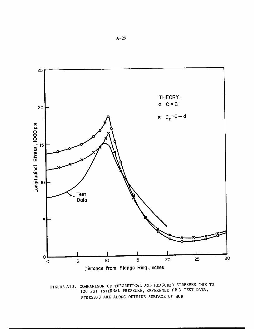
A-29
10 15 20
Distance from Flange Ring,inches
25
FIGURE AlO. COMPARISON OF THEORETICAL AND MEASURED STRESSES DUE TO100 PSI INTERNAL PRESSURE, REFERENCE (8 ) TEST DATA,STRESSES ARE ALONG OUTSIDE SURFACE OF HUB
30

A-30
Figure AlO as C = C-d. These are calculated as previously discussed
except using h^ = 4.469 - j = 4.469 - 0.75 = 3.719 in. Considering
the basis of the theory, the agreement between measured and calculated
stresses is as good as should be anticipated.
Tests on ANSI B16.5 Flanged Joints with Asbestos Gaskets,Bolt Stress Change with Pressure
Reference (9), Figure 10, gives test data on the variation of
bolt stress (measured with strain gages) with internal pressure.
The data for welding neck flanges are shown in Figure All, along
with theoretical results obtained using the computer program FLANGE.
In this set of tests, there are two major uncertainties in
application of the theory:
(1) What is the effective gasket diameter, G ?
(.2) What is the effective modulus of elasticity of
the asbestos gasket material?
The gasket widths in these tests are such that the value of Ge
is a lesser problem than in the previously discussed tests of the large
flanges with 0-ring gaskets. Accordingly, in this set of calculations
we have used the gasket mean diameter as G .e
The modulus of elasticity of an asbestos gasket varies with
bolt stress, time under load, and temperature. For new gaskets,
tested within a few hours after installation, Reference (10) gives an
equation for approximating the gasket modulus of such "newly installed"
gaskets which is about 50,000 to 100,000 psi for the tests under con
sideration. Reference (3) suggests that the effective modulus of elasticity
of asbestos gaskets may be around 1,000,000 psi. In some flanged joints,
the bolt stress variation with pressure would not be much different for

v>a.
OOO
toM
c
o
CD
A-31
r^rrn ( j r
- 10
V\
\• •
V.e
i 1 r t r
8 150 Class, Aluminum
Test No. IEg= "10 Eg =10*
r^r"1 ' h I I 1 1 1 1-
- 10
s?\
• • • . •
\
No610
8' 150 Class, Aluminum
Test No. 2
H 1 1 1- H H
12 300 Class, Aluminum
• ••••••
10'
10 - Test No. 510
H 1 1 1 1 I 1 h
10 h
0
-10
Test No. 6
u _ I •• I'
Test No. 9
12" 300 Class, Aluminum
6
10'• •
10
Eg. IP"
12" 300 Class, Aluminum
• • •
• • •
6 _Eg =10
J L J L
0 2 4 6 8 10 12 14 16 18 20 22
Internal Pressure, 100 psi
FIGURE All. COMPARISONS OF THEORETICAL AND MEASURED CHANGE INBOLT STRESS WITH PRESSURE, REFERENCE (9 ) TESTDATA.

A-32
E = 105 psi than for E = 10 psi. However, for the particular flangedp g
ioints under consideration, there is a significant difference. Figure AllS 6
shows the calculated bolt stress variations assuming E = 10 or E = 10
psi.
If we assume that the effective modulus of elasticity of the
asbestos gaskets is proportional to the initial gasket stress, and the
initial bolt stress is the same for all tests, then the 8" flanges should
have a smaller modulus than the 12" flanges. This is because the ratio
of bolt area to gasket area is 0.123 for the 8" flange; 0.346 for the 12"
flanges. A qualitative trend in this direction can be seen in Figure All.
It is pertinent to note that further increase in the assumed
value of E above 10 psi does not lead to a greatly increased prediction8
of the rate of bolt stress change with pressure. This point can be
illustrated by considering the values of AS / P for E = 10 , 10 and6
30 x 10 as tabulated below.
FlangedJoint
AS,b/AP for E
gof:
105 psi 106 psi 30 x 106 psi
8" Aluminum
12" Aluminum
12" Steel
10.2
4.0
-0.29
19.9
7.5
5.2
21.3
8.0
6.1
A-33
LEAKAGE PRESSURE TESTS
Because leakage is usually the "failure criterion" for
flanged joints, one might expect to find numerous test data in which
the leakage pressure of a flanged joint was determined. Such is not
the case. Back in 1936, the British "Pipe Flanges Research Committee"
published a few results of this type; but, the tests were not
really on flanged joints because the load was externally applied and
controlled; not applied by tightening the bolts. However, they did
find (1gaskets
find that the following relationship held for a variety of metal
where
(tt/4) G2 Pt = W (A7)O L
G = gasket outside diametero
P = leakage pressureJ-i
W = total load
Petrie published results of leakage pressure tests where
the load was applied by tightening the bolts in a flanged joint. Details
of the joints that he tested are not given nor is the method of measuring the
bolt stress described. His results, for flat gaskets, are shown in
Table A3. Petrie introduced the idea of a "performance factor", shown
in the last column of Table A3 and defined as:
W (ttG //nPtJB. . _£/ALJl (A8)wb 'bA

A-34
TABLE A3. LEAKAGE PRESSURE TESTS OF FLAT GASKETS IN FLANGED JOINTS,DATA FROM REFERENCE (5).
Flange Bolts,O.D., No. and Gasket Sbl PT ,
in. Size Material O.D.,in.'
I.D.,in.'
psiL!
psi P b
14.625 12-1 1/4 Akro Metal 9.0625 7.375 40,500 5,000 0.712tf
48,000 6,500 0.780
66,000 10,000 0.874
12.5 16-5/8 Akro Metal 8.875 7.75 35,000 1,600 0.877
70,000 2,200 0.602
105,000 3,300 0.604
120,000 4,000 0.643
25.5IT
16-1 7/8It
Asbestosii
14.25ti
13.50 21,400 3,900 0.908
28,500 5,000 0.872
15.00 13.50 35,700 6,000 0.927Akro Metal 14.25 13.50 28,500 5,600 0.976
46,800 6,200 0.660Copper 14.25 13.50 46,800 6,200 0.660Copper 15.00 13.50 46,800 5,800 0.617

where
A-35
G = gasket outside diameter
P = leakage pressureLi
S,. = initial bolt stressbl
\ = total bolt area
Equation (A8) is, of course, an axial force equilibrium equation; valid if S a
PT is equal to S, - at P = 0. If S.„ decreases as P increases, then W Ik,L bl b2 p b
will be less than unity. Equation (A8) also assumes that a gasket cannot
carry a tensile load; an assumption of doubtful general validity for
asbestos gaskets.
Table A3 shows W /W, consistently less than unity; in contrastP d
to Reference (11) tests where W /W, (with load controlled externally) wasP D
essentially equal to unity. This suggests that in Petrie's tests the
bolt load did decrease with pressure. However, details of the flanges
are not known, hence no theoretical comparisons can be made.
Reference (11) states that leakage pressure tests were made
using water as the pressurizing fluid and that "the first signs of
hydraulic leakage were easily and accurately determined by visual ob
servation". Reference (5) does not state what fluid was used nor how
leakage was determined. The writer would guess that the fluid was
water; with leakage detected by visual observation.
During the years between 1937 and to-date, only a few papers
have been published giving data on leakage pressures of flange joints.(9)
One of these , along with data from unpublished reports of Tube Turns
(Division of Chemetron), are discussed in the following. These are all
tests on ANSI B16.5 flanged joints and thus are particularly relevant
to this report. The test procedure was generally as follows.
A-36
(1) A flanged joint was made up with a new asbestos gasket.
The bolts were tightened with a torque wrench to a desired
stress level. The bolt stress was determined either
directly with strain gages in the bolts or indirectly by
calculations of torque versus bolt load.
(2) Using water as the pressurizing fluid, the pressure was
raised in steps until leakage occurred as evidenced by
drops of water emerging from the flanged joint within a
short time after applying the pressure step.
(3) Provided the gasket remained intact, the pressure was then
reduced to zero, the bolts were tightened to a higher
level and the leakage pressure was determined again.
Tables A4 thru A9 give results from these tests. Each table
shows the flange material, bolt material, pipe material, and gasket
material and dimensions. The flange dimensions are specified in ANSI
B16.5.
Each table gives:
(a) The initial bolt stress, S, 1. It should be emphasized that
this is not necessarily and generally is not the bolt stress
at pressure.
(b) The leakage pressure, P .
(c) The performance factor, W /W , as defined by Equation (A8).
(d) Calculated (Computer program FLANGE, IBOND = 2) maximum
flange stresses. Stresses are shown for the initial bolt
load, for pressure and for the sum of the two loads. The latter
(combined) stress is valid only if the initial bolt load
does not change with pressure.
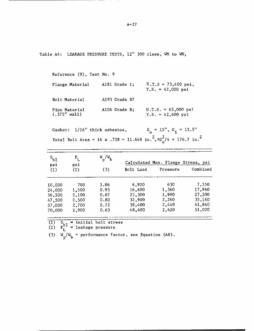
A-37
Table A4: LEAKAGE PRESSURE TESTS, 12" 300 class, WN to WN,
Reference (9), Test No. 9
Flange Material A181 Grade 1; U.T.S = 73,400 psi,Y.S. = 42,000 psi
Bolt Material A193 Grade B7
Pipe Material A106 Grade B; U.T.S. = 65,000 psi(.375" wall) Y.S. = 42,600 psi
Gasket: 1/16" thick asbestos, G = 15", G. = 13.5"o 1
Total Bolt Area = 16 x .728 = 11.648 in.2,rrG2/4 = 176.7 in.2o
Ki pT w /Kbl L p bCalculated Max. Flange Stress, psi
psi psi fi t—tl—(1) (2) (3) Bolt Load Pressure Combined
10,000 700 1.06 6,920 630 7,55024,000 1,500 0.95 16,600 1,360 17,96036,500 2,100 0.87 25,300 1,900 27,20047,500 2,500 0.80 32,900 2,260 35,16057,000 2,700 0.72 39,400 2,440 41,84070,000 2,900 0.63 48,400 2,620 51,020
(1) S,-.= initial bolt stress
(2) P = leakage pressureJ_i
(3) W /W, = performance factor, see Equation (A8).P d

A-38
Table A5: LEAKAGE PRESSURE TESTS, 12" - 300 class, WN to WN,
Reference (9), Test No. 5
Flange Material: 6061-T6; U.T.S. = 45,400 psi,Y.S. = 38,800 psi
Bolt Material: A193 Grade B7 0.500" wall.
Pipe Material: 6061-T6; U.T.S. = 46,600 psi,(0.500" wall) Y.S. = 40,100 psi
Gasket: 1/16" thick asbestos, G = 15", G = 13.5"o 1
Total Bolt Area = 16 x.728 = 11.648 in.2, ttG2/4 = 176.7 in.2.o
sblpsi
PLpsi Wtn/WkP D
Calculated Max. Flange Stress, psi
Bolt Load Pressure Combined
6,000 300 0.76 4,010 320 4,33010,000 550 0.83 6,680 590 7,27013,000 800 0.93 8,700 860 9,56015,000 950 0.96 10,020 1,030 11,05017,500 1,100 0.95 11,690 1,190 12,88022,500 1,200 0.81 15,030 1,300 16,33027,500 1,350 0.74 18,380 1,460 19,84036,000 1,600 0.67 24,050 1,730 25,78040,000 1,800 0.68 26,730 1,940 28,70048,000 1,850 0.58 32,070 2,000 34,07093,000 2,850 0.46 62,140 3,080 65,220

A-39
Table A6: LEAKAGE PRESSURE TESTS, 8" - 150 class, WN to WN,0.322 THICK ATTACHED PIPE (ALUMINUM)
Reference (9), Test No. 1
Flange Material: 6061-T6; U.T.S. = 47,800 psi,
Y.S. = 43,100 psi
Bolt Material: A193 Grade B7
Pipe Material: 3003-F; U.T.S. = 14,000 psi(0.322" wall) Y.S. = 5,000 psi
Gasket: 1/16" thick asbestos, G = 10.625", G. = 9.375"o 1
2 2Total Bolt Area: = 8 x 0.302 = 2.416 in. , ttG /4 = 88.66 in.
sblpsi
PLpsi
W /W,P d
Calculated Max. Flange Stress
Bolt Load Pressure Combined
9,500
17,00031,00059,000
300
600
920
1,070 *
1.16
1.30
1.09
3,2905,890
10,75020,460
500
1,0601,6301,890
3,7906,950
12,38022,350
* Pipe ruptured at 1,070 psi.
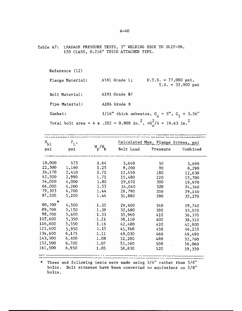
A-40
Table A7: LEAKAGE PRESSURE TESTS, 3" WELDING NECK TO SLIP-ON,150 CLASS, 0.216" THICK ATTACHED PIPE.
Reference (12)
Flange Material: A181 Grade 1; U.T.S. = 77,000 psi,Y.S. = 35,900 psi
Bolt Material: A193 Grade B7
Pipe Material: A106 Grade B
Gasket: 1/16" thick asbestos, G = 5", G. = 3.56"o 1
Total bolt area = 4 x .202 = 0.808 in. , ttG2/4 = 19.63 in.o
sbl VW /W
Calculated Max. Flange Stress, psi
psi psi P b Bolt Load Pressure Combined
10,000 675 1.64 3,640 50 3,69022,500 1,160 1.25 8,200 90 8,29034,170 2,410 1.71 12,450 180 12,63042,500 2,990 1.71 15,480 220 15,70054,000 4,000 1.80 19,670 300 19,97066,000 4,200 1.55 24,040 320 24,36079,303 4,700 1.44 28,790 350 29,14087,500 5,200 1.44 31,880 390 32,270
80,700 4,500 1.35 29,400 340 29,74089,700 5,150 1.39 32,680 390 33,07098,700 5,400 1.33 35,960 410 36,370
107,600 5,350 1.21 38,110 400 38,510116,600 5,550 1.16 42,480 420 42,900125,600 5,950 1.15 45,760 450 46,210134,600 6,175 1.11 49,030 460 49,490143,500 6,400 1.08 52,280 480 52,760152,500 6,700 1.07 55,560 500 56,060161,500 6,950 1.05 58,830 520 59,350
These and following tests were made using 3/4" rather than 5/8"bolts. Bolt stresses have been converted to equivalent on 5/8"bolts.

A-41
Table A8: LEAKAGE PRESSURE TESTS, 4" 900 CLASS WELDING NECK TOWELDING NECK, CAPS WELDED TO FLANGES
Reference (13)
Flange Material:
Bolt Material:
Pipe Material:
Gasket:
A105 Grade 2;
A193 Grade B7
A106 Grade B (caps)
U.T.S. - 63,000 psi ,Y.S. = 30,600 psi
1/16" thick asbestos, G = 6.1875", G. = 4.5"o 1
Total Bolt Area = 8 x .728 = 5.824 in.2. ttG2/4 = 30.07 in.2,o
sblpsi
PL>psi P °
Calculated Max. Flange Stress, psi
Bolt Load Pressure Combined
8,400 350 0.22 9,400 -30 9,370
16,900 4,500 1.37 18,920 -440 18,480
25,400 6,500 1.32 28,440 -640 27,800
33,800 8,300 1.27 37,840 -810 37,030
42,300 9,500 1.16 47,350 -930 46,420
50,700 10,500 1.07 56,760 -1030 55,730
55,800 11,000 1.02 62,460 -1080 61,380

Test
No.
(1) *
(2)
A-42
Table A9: LEAKAGE PRESSURE TESTS, 8" 150 CLASS, WELDING NECK TO WELDINGNECK AND 8" FLANGES WITH REDUCED FLANGE THICKNESS
Reference (14),
Bolt Material:
Pipe Material:
Gasket:
Yield
Strengthpsi
55,40088,80035,500
35,50088,80088,80035,500
FlangeThickness,
in.
1.17
1.17
1.17
1.17
0.75
0.50
0.50
A193 Grade B7
A106 Grade B, 0.322" thick
1/16" thick asbestos, G = 10.625", G = 9.375"
Total Bolt Area = 8x .302 = 2.416 in.2 ttG2/4 = 88.66 in 2o
bl
psi
(1)
96,00096,00078,500*
83,000*130,400103,500*41,400*
PL>psi
3,250
2,9802,460
2,9303,2203,000
1,080
W /W,
1.24
1.14
1.25
1.30
0.91
1.06
0.96
Calculated Max. Flange Stress,psi
p'"b Bolt Load Pressure Combined
33,270
33,27026,40027,900
101,230182,60073,040
5580 38.,8505110 38,,3804220 30.,6205030 32,,9304510 96,,7203990 178,,6101440 71,,600
Indicates that load/pressure was sufficient to produce measurableyielding of the flanges.Maximum stress is LLO for tests 1, 2, 3,and 4; RH for tests 5, 6,and 7; see Figure 3 of text.
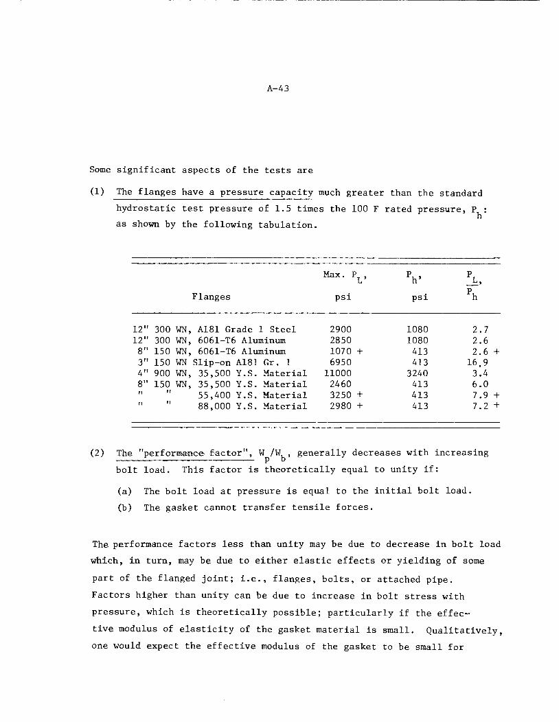
A-43
Some significant aspects of the tests are
(1) The flanges have a pressure capacity much greater than the standard
hydrostatic test pressure of 1.5 times the 100 F rated pressure, P :h
as shown by the following tabulation.
12
12
8
3
4
8
Flanges
300 WN, A181 Grade 1 Steel
300 WN, 6061-T6 Aluminum150 WN, 6061-T6 Aluminum
150 WN Slip-on A181 Gr. 1900 WN, 35,500 Y.S. Material
150 WN, 35,500 Y.S. Material
55,400 Y.S. Material88,000 Y.S. Material
Max. P , V L,
psi psi
2900 1080 2.7
2850 1080 2.6
1070 + 413 2.6 +
6950 413 16.9
1000 3240 3.4
2460 413 6.0
3250 + 413 7.9 +
2980 + 413 7.2 +
(2) The "performance factor", W /W, generally decreases with increasing
bolt load. This factor is theoretically equal to unity if:
(a) The bolt load at pressure is equal to the initial bolt load.
(b) The gasket cannot transfer tensile forces.
The performance factors less than unity may be due to decrease in bolt load
which, in turn, may be due to either elastic effects or yielding of some
part of the flanged joint; i.e., flanges, bolts, or attached pipe.
Factors higher than unity can be due to increase in bolt stress with
pressure, which is theoretically possible; particularly if the effec
tive modulus of elasticity of the gasket material is small. Qualitatively,
one would expect the effective modulus of the gasket to be small for
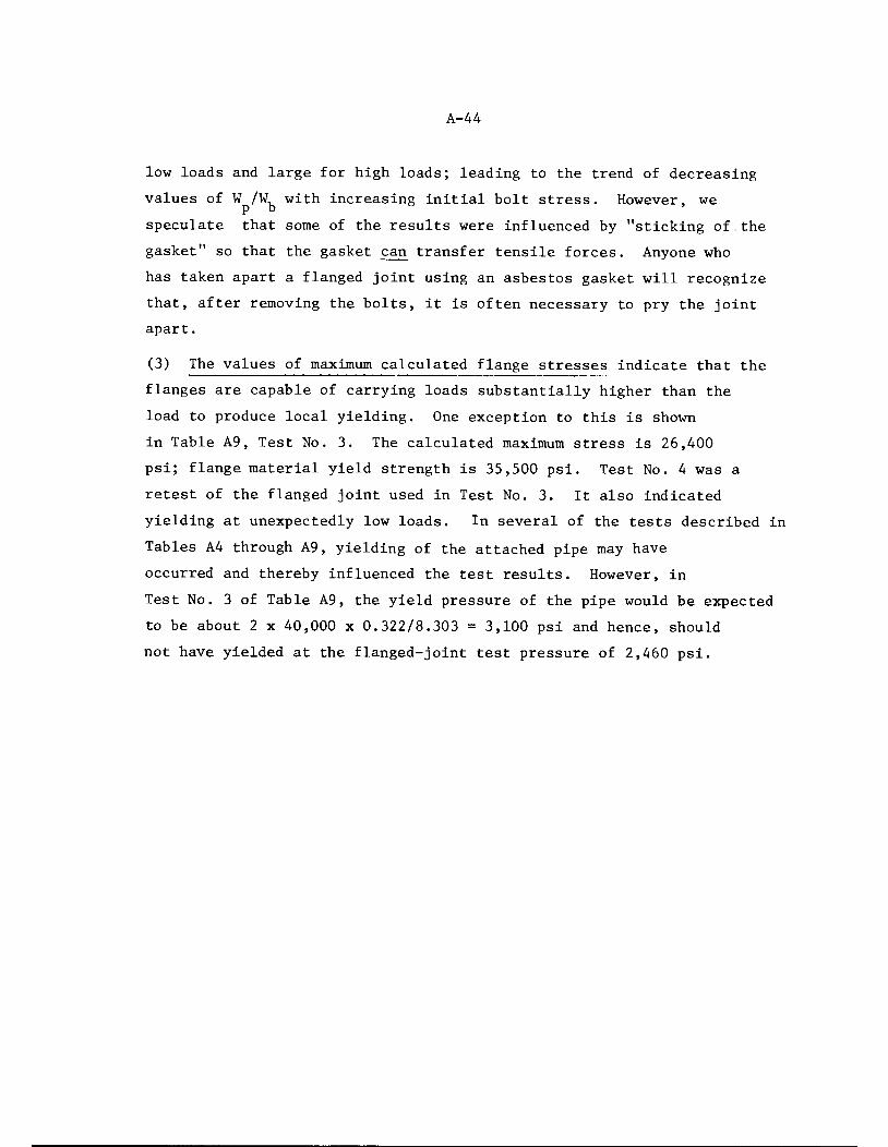
A-44
low loads and large for high loads; leading to the trend of decreasing
values of W /W, with increasing initial bolt stress. However, wep b '
speculate that some of the results were influenced by "sticking of.the
gasket" so that the gasket can transfer tensile forces. Anyone who
has taken apart a flanged joint using an asbestos gasket will recognize
that, after removing the bolts, it is often necessary to pry the joint
apart.
(3) The values of maximum calculated flange stresses indicate that the
flanges are capable of carrying loads substantially higher than the
load to produce local yielding. One exception to this is shown
in Table A9, Test No. 3. The calculated maximum stress is 26,400
psi; flange material yield strength is 35,500 psi. Test No. 4 was a
retest of the flanged joint used in Test No. 3. It also indicated
yielding at unexpectedly low loads. In several of the tests described in
Tables A4 through A9, yielding of the attached pipe may have
occurred and thereby influenced the test results. However, in
Test No. 3 of Table A9, the yield pressure of the pipe would be expected
to be about 2 x 40,000 x 0.322/8.303 = 3,100 psi and hence, should
not have yielded at the flanged-joint test pressure of 2,460 psi.

a-A^
TEST DATA WITH PIPE BENDING MOMENT
We have not found any published data on the effect of
pipe bending moments on flanged joints. References (18), (19), and
(20) give theoretical approaches for estimating the effect of pipe
bending moments, but do not include test data.
Data from unpublished reports of Tube Turns Division of
Chemetron are presented in the following and compared with text
Equations (7) and (17). These are "leakage pressure tests", but with
the addition of a pipe bending moment. The data are for tests on
4" 300 class, 3" 150 class, and 12" 150 class B16.5 welding neck
flanged joints. The flanges were made of SA-181 Grade 1 material;
bolts were SA-193 Grade B7 material; gaskets were 1/16" thick asbestos
with diameters as shown below.
Gasket
Flange O.D. ,in.
I.D. ,in.
4" 300
3" 150
12" 150
6-3/16"5"
15"
4"
3-9/16"12.25"
The attached pipe was SA-106 Grade B material with wall thicknesses of
0.237", 0.216", and 0.250" for the 4-300, 3-150, and 12-150 flanged
joints, respectively.
Thfi test procedure was generally as follows.
(1) A flanged joint was made up with a new asbestos gasket. The bolts were
tightened with a torque wrench to a desired stress level. The
bolt stress was determined either directly with strain gages on
the bolts or indirectly by calibration of torque vs bolt load.
A-46
(2) Using water as a pressurizing fluid, the pressure was raised
in steps until leakage occurred as evidenced by drops of water
emerging from the flanged joint within a short time after applying
the pressure step. The leakage pressure so obtained is the zero
pipe bending moment leakage pressure plotted in Figure A12 through A17.
(3) The pressure was then reduced to zero and a bending force was
applied to one of the attached pipes; the other attached pipe
was anchored. The axial distance from the load application to
the gasket of the flanged joint was 35", 20", and 60" for the
4-300, 3-150, and 12-150 flanged joints, respectively. The applied
moment is given in the References and is the force times the distance from
the point of force application to the gasket. The leakage pressure
was then determined as in Step (2).
(4) Step (3) was repeated with higher bending forces.
(5) The bolts were then further tightened and steps (2) thru (4) were
repeated.
(6) An upper limit on applied pressures was imposed of 1,650 psi for
the 4" - 300 class and 625 psi for the 12" - 150 class.
The results are shown in Figures A12 thru A17 as plots of
pipe bending moment versus leakage pressure.
Figures A12, A13, and A14 also show the pipe bending moment
versus leakage pressure relationships from text Equation (7), using
S = S, ,, and S, , = initial bolt stress. It is apparent that Equationm bl bl
(7), which is the Code NB-3647.1(b) limitation of pipe bending moments
as controlled by bolt stress, is quite conservative with respect to
the test data. For example, in Figure A12 Equation (7) implies that
the joint is not capable of carrying any pressure with a pipe bending
moment of 82,000 in.-lb with an initial bolt stress of 25,100 psi whereas
the test data indicate that the flanged joint can hold more than 1,650 psi
pressure at these conditions.

a.
OO
73</></>
fiQ.
a>
oJ*
o
24
22
20
18
t®
I6i-
14 -
12 -
Test Data
Symbol Sbl
D 8750
X 17800
O 25100
t Did not leak
f®
A-47
r
Theory, Eq. (7)
© I
H-J-40 60 80 100
Pipe Bending Moment, 1000 in -lb
120
FIGURE A12: LEAKAGE PRESSURES, 4"-300 FLANGED JOINT, TEST DATA FROMREFERENCE (10), THEORY FROM TEXT EQ. (7).
G

A-48
32
30
A A
28
r26©
24
22
._ 20CO
Q.
o
9 I8h
w 16
o l4c
cu
•S 12
10 -
Test Data
Symbols sbla 9800
X 19985
o 29450
A 43120
8 CD-
Theory, Eq.(7)
10 20 30 40
Pipe Bending Moment, 1000 in-lb
FIGURE A13: LEAKAGE PRESSURES, 3"-150 FLANGED JOINT,TEST DATA FROM REFERENCE (12), THEORYFROM TEXT EQ. (7).
50

A-49
Test Data o Sb, =40000 psit Did not leak
060
Theory, Eq.(7)
Dl 2345 6789
Pipe Bending Moment, 100,000 In-lb.
FIGURE A14: LEAKAGE PRESSURES, 12"-150 FLANGED JOINT,TEST DATA FROM REFERENCE (15), THEORYFROM TEXT EQ. (7).
wQ.
oO
2>
8
cr»o
a
20
A-50
Test Data
Symbols Sw , psia 8750
X 17800
O 25100
t Did not leak
4 0 60 80
Pipe Bending Moment, 1000 in-lb
100
FIGURE A15: LEAKAGE PRESSURES, 4"-300 FLANGED JOINT, TEST DATA FROMREFERENCE (10), THEORY FROM TEXT EQ. (17).
120

32
30
coQ.
OO
£3(ACOCD
o»O
aCD
& A
A-51
Test Data
ibc»ls Sb| , ps«D 9800
X 19985
0 29450
A 43120
Theory
Ea = 3xl07psi
Theory
Eg=650l/S7,
20 30 4 0 5 0
Pipe Bending Moment, 1000 in-lb
FIGURE A16: LEAKAGE PRESSURES, 3"-150 FLANGED JOINT, TEST DATAFROM REFERENCE (12), THEORY FROM TEXT EQ. (17).
60
12
TheoryEa 3x10 psi
A-52
Test Data ° Sb|= 40000 psit Did not leak
Theory
Eg =650 -/S gi
_L
234 56 78 9
Pipe Bending Moment, 100,000 in-lb
10
FIGURE A17: LEAKAGE PRESSURES, 12"-150 FLANGED JOINT, TESTDATA FROM REFERENCE (15), THEORY FROM TEXT EQ.
(17).

A-53
Figures A15, A16, and A17 show the test data along with two
sets of theoretical pipe bending moment vs pressure relationships. Both
are based on Equation (17) of the text; with the "40,000" replaced by
the initial bolt stress, S,,, used in the tests. The first set, shownbl
as dashed lines in Figure A15, A16, and A17, are based on a modulus of
elasticity of the gasket of E = 3 x 10 psi. These lines are also
quite conservative with respect to the test data.
The calculations using E = 3 x 10 psi were made because
this is the assumed modulus used in calculations for the tables shown
in the text. In our opinion, E = 3 x 10 psi is an appropriate
representation of the characteristics of an asbestos gasket in a B16.5
flanged joint after the bolts have been tightened to 40,000 psi and the
joint has been in service for several years. However, at this point, we
are attempting to see how theory correlates with test data, when the
tests were partly run with low bolt stresses and the tests were run
immediately (within a few hours) after making up the joint.
Reference (10) summarizes tests on various 1/16" and 1/8"
thick asbestos gasket materials compressed between platens to
determine the effective modulus of elasticity. Not all details of
these tests are known (e.g., size of test piece; time-effects, if
any) and they are non-linear; E increases with gasket stress, S .
However, over the range of S from 200 to 6,000 psi, E is at least
approximately represented by the equation:
where S ., = S...A,/Agl bit) f
E = 650 JS 1 (A9)g X gl

A-54
The solid lines shown in Figures A15, A16, and A17 are based on a., and
a„ values calculated using E from Equation (A9). It can be seen in
Figures A15, A16, and A17 that use of these more realistic (but still
very approximate) values for E gives significantly improved correlation
with the test data.
One notes in Figure A16 that the solid line for S, ., = 9,800bl
slopes upward. The theory indicates that with S,- = 9,800 and the
corresponding S = 818 psi, E = 18,590 psi, the joint is "self-sealing"
for pipe bending moments. We do not see such a trend in the test data
for S, 1 = 9,800 psi but such a trend is apparent for SK1 = 19,985 psi and
S = 43,120 psi.
Another bit of pertinent data is given in the paper by Markl
and George . In running cyclic pipe bending loading fatigue tests
on 4" - 300 class flanged joints with 0.237" wall attached pipe, they
note that an initial bolt stress of 40,000 psi was sufficient to pre
vent leakage, but that at an initial bolt stress of 24,000 psi was not
sufficient for "specimens subjected to high deflections". Their results
indicate that they imposed bending stress of S up to 60,000 psi in the
attached pipe. In most tests, the internal pressure was essentially
zero (25" head of water to detect leakage). In some tests, an internal
pressure of 600 psi was applied.
Values of S , calculated by text Equations (7) and (17) are
as folliDWS
Sbl'psi
Pressure,
psi
Calculated Spb (Psi)Eq. (7) Eq,. (17)
24,000 0 20,,950 15,,430600 8,,350 10,,010
40,000 0 34,,920 25,,720600 22,,320 20,,300
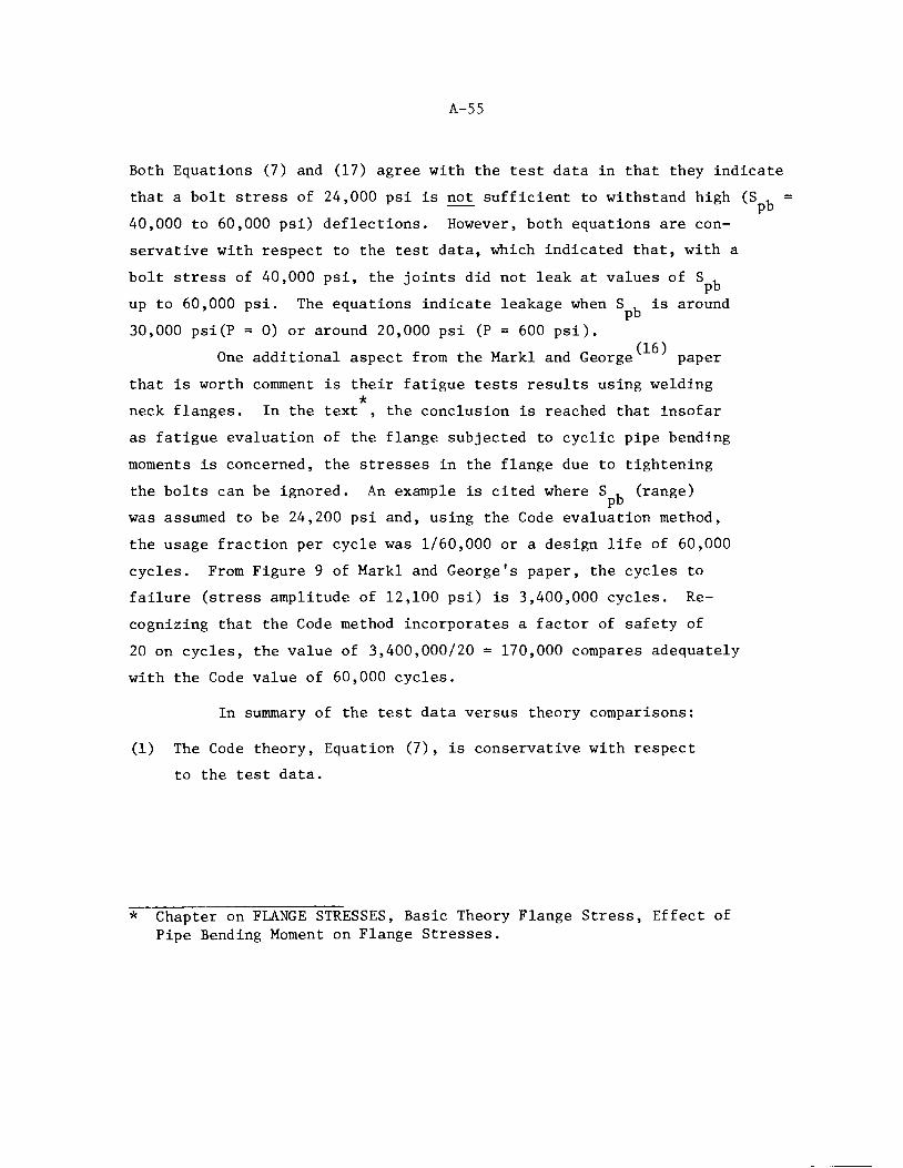
A-55
Both Equations (7) and (17) agree with the test data in that they indicate
that a bolt stress of 24,000 psi is not sufficient to withstand high (S , =
40,000 to 60,000 psi) deflections. However, both equations are con
servative with respect to the test data, which indicated that, with a
bolt stress of 40,000 psi, the joints did not leak at values of Spb
>n S , is arcpb
30,000 psi(P = 0) or around 20,000 psi (P = 600 psi).
One additional aspect from the Markl and George paper
that is worth comment is their fatigue tests results using welding
neck flanges. In the text , the conclusion is reached that insofar
as fatigue evaluation of the flange subjected to cyclic pipe bending
moments is concerned, the stresses in the flange due to tightening
the bolts can be ignored. An example is cited where S , (range)pb
was assumed to be 24,200 psi and, using the Code evaluation method,
the usage fraction per cycle was 1/60,000 or a design life of 60,000
cycles. From Figure 9 of Markl and George's paper, the cycles to
failure (stress amplitude of 12,100 psi) is 3,400,000 cycles. Re
cognizing that the Code method incorporates a factor of safety of
20 on cycles, the value of 3,400,000/20 = 170,000 compares adequately
with the Code value of 60,000 cycles.
In summary of the test data versus theory comparisons:
(1) The Code theory, Equation (7), is conservative with respect
to the test data.
up to 60,000 psi. The equations indicate leakage when S , is around
* Chapter on FLANGE STRESSES, Basic Theory Flange Stress, Effect ofPipe Bending Moment on Flange Stresses.

A-56
(2) The basic theory, Equation (17) using E = 3 x 10 psi, is
conservative with respect to the test data,
(3) The basic theory, Equation (17) using E = 650^/S ...instead of
E = 3 x 10 psi, gives better agreement with the test data and,g
considering the many uncertainties involved in the tests and
approximations involved in the theory, the agreement is about as
good as should be expected.
APPENDIX B
DEVELOPMENT OF SIMPLE EQUATIONS FOR LIMITATION
OF PIPE BENDING AND TORSIONAL MOMENTS
TABLE OF CONTENTS
Page
INTRODUCTION B-l
BOLTING STRENGTH REQUIREMENTS B-l
FLANGE STRENGTH REQUIREMENTS B-10
EMERGENCY CONDITIONS B-12
FAULTED CONDITIONS B-15
TORSIONAL MOMENTS B-15


B-l
INTRODUCTION
The text of this report presents two methods of evaluating the
pressure and pipe bending moment capacity of flanged joints; i.e., the
method given in NB-3647.1 and the method incorporated in the computer
program FLANGE. The NB-3647.1 method for limiting pipe bending moments,
despite its complexity, can only be described as a very crude approxi
mation. The computer program FLANGE, while theoretically sounder, never-
the less uses rough approximations in the analysis for pipe bending moments.
As discussed in Appendix A, both methods appear to be highly conservative
with respect to available test data.
In this appendix, we will develop simple equations for limitation
of pipe bending moments starting with consideration of bolting strength re
quirements for normal and upset conditions. We then consider the flange
strength requirements and then examine limits for emergency and faulted
conditions. The equations developed herein are included as recommendations
for Code revisions in Appendix C.
BOLTING STRENGTH REQUIREMENTS
In the text, we have discussed criteria for minimum bolt area
which involve the concept of a "leakage pressure"; i.e., Equations (8)
and (10). Hopefully, the bolts will be prestressed to S, > S, so that
gross leakage will not occur. However, the Code does not directly im
pose any minimum on the bolt prestress. Practically, a minimum bolt
prestress becomes a necessity in order to pass the hydrostatic test and/
or not leak too much in service. The aim of the Code rules is to provide
a flanged joint which has sufficient strength so that the bolts can be
prestressed sufficiently to prevent gross leakage under sustained loadings
encountered in normal or upset conditions. In addition, the Code rules
should provide a flanged joint which will withstand dynamic loads en
countered in normal or upset conditions and, after the dynamic loads
stop, the joint will return to a condition where gross leakage will cease.

B-2
Finally, the Code rules should provide a flanged joint of sufficient
strength so that the bolts do not break as a result of emergency or
faulted conditions.
The stress in the bolts due to internal pressure is conser
vatively given by the equation:
where
°bp " <*'V Dr P/\ (Bl)
o, = bolt stress due to pressure
D_ = outside diameter of raised face
P = internal pressure
A, = total bolt area
The stress in the bolts due to a pipe bending moment can be
developed by assuming that the bolt area is uniformly distributed along
the bolt circle. The imaginary cylindrical shell so formed has a thick
ness of A^I-nC, where A^ = total bolt area, C = bolt circle diameter. Themaximum stress in this imaginary cylindrical shell due to pipe bending
moment is then:
o = M. = , Pb = pb (B2)bm Z (ir/4) C2 VOrC) ~C V4
Equation (B2) is based on the assumption that the neutral axis coincides
with a centerline of the imaginary pipe. This is not necessarily the case
for a flanged joint, but Equation (B2) will not be unconservative by
more than 11 percent, regardless of the neutral axis location. An equation
analogous to (B2) could also be developed using the discrete bolt areas;
the value of o"bm would then depend on the orientation of the neutral axis.If we assume the bolt diameter is small compared to the bolt circle dia
meter, then Equation (B2) gives the same answer as the discrete bolt area
approach when a pair of bolts are on the neutral axis. If the bolts
straddle the neutral axis, Equation (B2) gives higher stresses than the
discrete bolt area approach; by factors of 1.41, 1.08, and 1.04 for 4,8,
and 12 bolts, respectively.

B-3
Having Equations (Bl) and (B2), we now seek a simple equation to
establish the maximum bending moment that can be imposed on the flanged
joint as limited by the strength of the bolting.
According to ANSI B16.5 (Par. 6.9.6) the stress calculated by
Equation (Bl) does not exceed 7,000 psi when the pressure is eaual to
the primary rating pressure. Table Bl shows the calculated values of
a, using Equation (Bl). It can be seen from Table Bl that the statement
in B16.5 is essentially correct; only the 16" and 20" Class 900 slightly
exceed 7,000 psi. It can also be seen from Table Bl that, for most sizes
and classes, the value of o, is well below 7,000 psi. However, the
highest bolt stress due to pressure, in relationship to Code allowable
bolt stresses, occurs at the 100 F rating pressure rather than at the
primary rating pressure. The 100 F rating pressure does not exceed 2.4
times the primary rating pressure, hence, the upper bound to o" at thebp
100 F rating pressure is 2.4 x 7,000 = 16,800 psi. If the Code allowable
bolt stress at 100 F is 20,000 psi or higher, we can conservatively assume
that the bolt strength needed to hold the design pressure will not exceed
the Code allowable bolt stress, S, .b
The lower limit on S, of 20,000 psi at 100 F is deemed desirable
so that the bolts can be prestressed to 40,000 psi without violation of NB-3232,
In the remainder of this portion on bolting strength requirements, we will
use S, to indicate the allowable bolt strength as given in Code Table 1-1.3
However, from flange strength considerations, we cannot use a value of S,b
greater than 25,000 psi. Accordingly, in examples and Tables, we will be
using S, = 25,000 psi and, in our final recommendations, S, will be replaced
by 25,000 psi.
Having assigned 1.0 S, of the total bolt strength to pressure
loading, what remains for moment loading? In NB-3232.1, we note that the
bolt stress is permitted to be 2.0 S . The extra 1.0 S, , for our purpose,
can be allotted to bolt strength needed to hold the pipe bending moment.
We then simply use Equation (B2), with S, used in place of o, , and solveb bm

B-4
TABLE Bl: BOLT STRESSES BY THE EQUATION a =(ir/4) D^ P/A^
Nom. bp= bolt stress at primary rat ing pressure, psi
Size 150 300 400 600 900 1,500 2,500
1/2 440 880 __ 1,770 1,840 3,0703/4 670 830 — 1,660 — 2,780 4,630
1 930 1,170 — 2,330 — 2,810 4,6901-1/4 1,460 1,820 — 3,640 — 4,390 5,5701-1/2 1,930 1,610 — 3,220 — 4,420 5,570
2 1,920 1,920 — 3,830 4,620 5,8502-1/2 2,480 1,660 — 3,320 — 4,550 5,7403 3,640 2,440 — 4,880 5,270 5,060 6,6003-1/2 2,200 2,950 — 4,250 — — —
4 2,790 3,730 3,590 5,380 4,650 6,070 6,690
5 2,610 5,210 5,010 5,720 5,090 5,600 6,6306 3,520 4,700 4,510 5,150 5,850 6,140 6,6908 5,500 5,290 5,360 6,090 5,760 6,600 6,96010 3,810 4,340 4,380 5,150 6,220 6,930 6,20012 5,270 4,550 4,760 5,710 6,890 6,250 7,000
14 4,710 4,270 4,460 5,390 6,640 5,68016 4,570 4,340 4,650 5,740 7,200 5,87018 4,460 4,660 5,000 6,180 6,765 6,17020 4,280 5,590 4,930 6,180 7,050 6,16024 4,710 5,190 4,910 6,330 6,110 6,250 —
P = primary rating pressure, psi
A^ = total bolt area, sq-in.
D = outside diameter of raised face, inches,
B-5
for M , to obtain:pb
> ±CVb/4 <B3>
Equation (B3) provides a limit on M based on strength of the bolts;
it does not necessarily limit M so that gross leakage will not occur.
There are no test data available in which flanged joints were loaded
with pressure and/or pipe bending moment sufficient to break (or even
yield) the bolts. However, the data given in Appendix A show that
moments well in excess of these permitted by Equation (B3) have been
applied to flanged joints.
Equation (B3) provides a very simple method for limiting M withpb
respect to bolt strength. It would be very useful to obtain a similar
simple equation for limiting M , with respect to joint leakage. NB-3647.1
provides a method for limiting M but its complexity is not compatible
with its accuracy. The computer program FLANGE is deemed to be a more
accurate method, but it can not be made a part of Code rules. Let us see
what happens if we consider Equation (B3) as representing the essential
variables (C, A, , S, ) needed to represent joint leakage, but multiply the
right hand side by one-half; i.e.,
V -c S V8 (B4)
Table B2 compares allowable pipe bending stresses as obtained
from Equation (B4) with allowable pipe bending stresses obtained by the
NB-3647.1 procedure and from the computer program FLANGE. It can be seen
in Table B2 that Equation (B4) is a reasonably good approximation of the
moment limits calculated using the computer program FLANGE.
To check Equation (B4) experimentally, we would like to have
test data on flanged joints in which the bolt prestress is 40,000 psi,
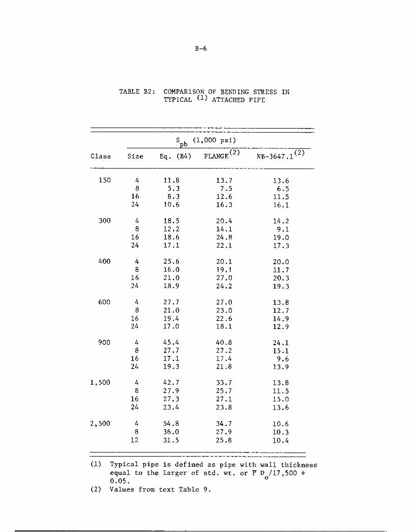
B-6
TABLE B2: COMPARISON OF BENDING STRESS IN
TYPICAL (!) ATTACHED PIPE
Spb (1 ,000 psi)
Class Size Eq. (B4) FLANGE^ NB-3647.1(2)
150 4 11.8 13.7 13.6
8 5.3 7.5 6.5
16 8.3 12.6 11.5
24 10.6 16.3 16.1
300 4 18.5 20.4 14.2
8 12.2 14.1 9.1
16 18.6 24.8 19.0
24 17.1 22.1 17.3
400 4 25.6 20.1 20.0
8 16.0 19.1 11.7
16 21.0 27.0 20.3
24 18.9 24.2 19.3
600 4 27.7 27.0 13.8
8 21.0 23.0 12.7
16 19.4 22.6 14.9
24 17.0 18.1 12.9
900 4 45.4 40.8 24.1
8 27.7 27.2 15.1
16 17.1 17.4 9.6
24 19.3 21.8 13.9
1,500 4 42.7 33.7 13.8
8 27.9 25.7 11.5
16 27.3 27.1 15.0
24 23.4 23.8 13.6
2,500 4 54.8 34.7 10.6
8 36.0 27.9 10.3
12 31.5 25.8 10.4
(1) Typical pipe is defined as pipe with wall thicknessequal to the larger of std. wt. or F D /17,500 +0.05. °
(2) Values from text Table 9.

B-7
internal pressure is equal to the rated pressure and the pipe bending
moment is increased until leakage occurs. Data given in Appendix A is
not ideal in this sense, but it can be used. Figure A14 represents
perhaps the best test for the purpose because the initial bolt stress
was 40,000 psi. Equation (B4), with S, = 25,000 psi, gives M ,_ = 267,000b pb
in.-lb. It can be seen in Figure A14 that there was no leakage at this
moment, even though the pressure was 625 psi rather than the rated pressure
of 275 psi at 100 F. Indeed, the data suggest that the moment could be
doubled before leakage at 625 psi occurs. Figures A12 and A13 also indicate
that Equation (B4) is highly conservative.
It is pertinent at this point to discuss the magnitudes of
moments that can be applied to flanged joints in comparison to the moments
that can be applied to straight pipe. Table B3 shows the stresses in
"typical" attached pipe where the maximum moment is calculated by Equation
(B3) with S^ = 25,000 psi. Typical pipe is defined as pipe with wallthickness equal to the larger of std. wt. wall or P D /17,500 + 0.05.
As a yardstick for comparison, the stress in straight pipe due
to thermal expansion and anchor movements is permitted to be 3 S . Them
value of S for A-106 Grade B pipe at 100 F is 23.3 ksi; 3 S =69.9 ksi.m r m
It is apparent from Table B3 that many small size flanges have an "allowable
pipe bending stress" by Equation (B3) that is greater than 69.9 ksi. On
the other hand, for many flanged joints, the permissible moment will be
severely restricted; e.g., the 8" - 150 class where the allowable moment
is 10.6/69.9 times that permitted on 8" Std. wt. A-106 Grade B pipe at 100 F.
Table B4 shows the stresses in "typical" attached pipe where the
maximum moment is calculated by Equation (B4) with S, = 25,000 psi. These
values, of course, are simply one-half of those shown in Table B3. It is
apparent in Table B4 that only a few small size flanged joints will not be
restricted in permissible moment as compared to "typical" straight pipe.
The larger sizes of the 150 class are severely restricted; e.g., the 8" -
150 class is limited to a moment of 0.076 times that for 8" std. wt. A-106
Grade B pipe at 100 F. In the smaller sizes of the 150 class, the 3" size
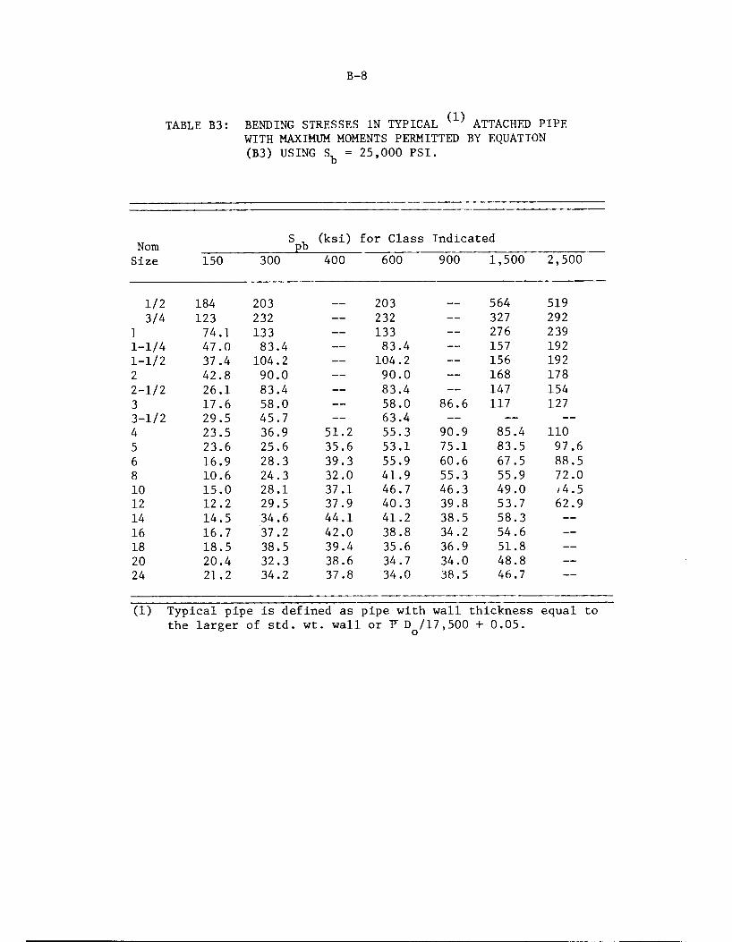
B-8
TABLE B3: BENDING STRESSES IN TYPICAL ( ) ATTACHED PIPEWITH MAXIMUM MOMENTS PERMITTED BY EQUATION
(B3) USING S,_ = 25,000 PSI.b
Nom S Vpb(ksi) for Class Indicated
Size 150 300 400 600 900 1,500 2,500
1/2 184 203 203 — 564 519
3/4 123 232 — 232 — 327 292
1 74.1 133 — 133 — 276 239
1-1/4 47.0 83.4 — 83.4 — 157 192
1-1/2 37.4 104.2 — 104.2 — 156 192
2 42.8 90.0 — 90.0 — 168 178
2-1/2 26.1 83.4 — 83.4 — 147 154
3 17.6 58.0 — 58.0 86.6 117 127
3-1/2 29.5 45.7 — 63.4 — — —
4 23.5 36.9 51.2 55.3 90.9 85.4 110
5 23.6 25.6 35.6 53.1 75.1 83.5 97.6
6 16.9 28.3 39.3 55.9 60.6 67.5 88.5
8 10.6 24.3 32.0 41.9 55.3 55.9 72.0
10 15.0 28.1 37.1 46.7 46.3 49.0 /4.5
12 12.2 29.5 37.9 40.3 39.8 53.7 62.9
14 14.5 34.6 44.1 41.2 38.5 58.3 —
16 16.7 37.2 42.0 38.8 34.2 54.6 —
18 18.5 38.5 39.4 35.6 36.9 51.8 —
20 20.4 32.3 38.6 34.7 34.0 48.8 —
24 21.2 34.2 37.8 34.0 38.5 46.7 —
(1) Typical pipe is defined as pipe with wall thickness equal tothe larger of std. wt. wall or F D /17,500 + 0.05.
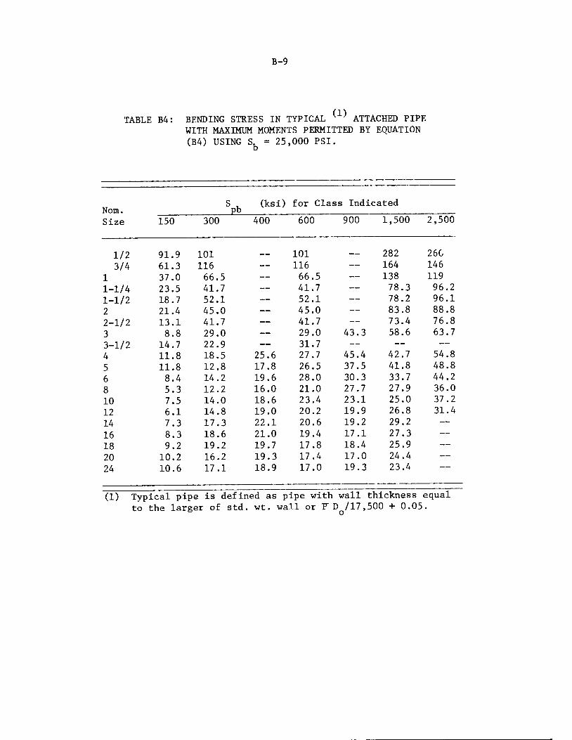
B-9
TABLE B4: BENDING STRESS IN TYPICAL ( ' ATTACHED PIPEWITH MAXIMUM MOMENTS PERMITTED BY EQUATION
(B4) USING S. = 25,000 PSI.b
• •- '- • ' ~
S , (ksi) for Claiss IndicatedNom. Pb
Size 150 300 400 600 900 1,500 2,500
1/2 91.9 101__ 101 — _ 282 260
3/4 61.3 116 — 116 — 164 146
1 37.0 66.5 — 66.5 — 138 119
1-1/4 23.5 41.7 — 41.7 — 78.3 96.2
1-1/2 18.7 52.1 — 52.1 — 78.2 96.1
2 21.4 45.0 — 45.0 — 83.8 88.8
2-1/2 13.1 41.7 — 41.7 — 73.4 76.8
3 8.8 29.0 — 29.0 43.3 58.6 63.7
3-1/2 14.7 22.9 — 31.7 — — —
4 11.8 18.5 25.6 27.7 45.4 42.7 54.8
5 11.8 12.8 17.8 26.5 37.5 41.8 48.8
6 8.4 14.2 19.6 28.0 30.3 33.7 44.2
8 5.3 12.2 16.0 21.0 27.7 27.9 36.0
10 7.5 14.0 18.6 23.4 23.1 25.0 37.2
12 6.1 14.8 19.0 20.2 19.9 26.8 31.4
14 7.3 17.3 22.1 20.6 19.2 29.2 —
16 8.3 18.6 21.0 19.4 17.1 27.3 —
18 9.2 19.2 19.7 17.8 18.4 25.9 —
20 10.2 16.2 19.3 17.4 17.0 24.4 —
24 10.6 17.1 18.9 17.0 19.3 23.4
(1) Typical pipe is defined as pipe with wall thickness equalto the larger of std. wt. wall or F D /17,500 + 0.05
B-10
is severely limited. These results correlate with field experience in that
leakage problems occur relatively frequently with the 3" and 8" 150 class.
Equation (B4) is deemed to provide a suitable limit for sus
tained moment loads. If the bolts are prestressed to 40,000 psi, the
flanged joint would not be expected to exhibit gross leakage with pressure
up to the rated pressure in combination with moments up to that permitted
by Equation (B4). For moments which act over a short period of time, the
higher moment limit of Equation (B3) is deemed appropriate. Leakage may
occur, but the bolts will remain elastic because the total strength re
quirement is, at most, 2 S, . The value of S, is not greater than one-third
of the bolt material yield strength.
FLANGE STRENGTH REQUIREMENTS
Table 18 of the text shows calculated flange stresses for a bolt
preload stress of 40,000 psi. As long as the pressure and pipe bending
loads do not reduce the gasket stress to zero, the flange stresses (except
in the hub) will not change significantly. By limiting the pressure to
the rated pressure and the sustained moment to S./2, we are essentiallyb
limiting the loads so that a prestress of 40,000 psi will not be exceeded.
The worst case is the 16" 900 class at 100 F for which a, + a,bp bm
7,200 x 2.4 + 12,500 = 29,780 psi. For short-time moments, the worst case
limit is 7,200 x 2.4 + 25,000 = 42,280 psi. B16.5 flanges are deemed to
have ample strength to withstand these loads.
In the above, we have taken S, = 25,000 psi, the allowable value
for SA-193 Grade B7 at temperatures up to 700 F in Code Table 1-7.3. If
we take S, from Code Table 1-1.3 (Class 1), we note that the allowable
stress for SA-193 Grade B7 is 35,000 psi at 100 F and that other bolt
materials have allowable stresses as high as 50,000 psi at 100 F. Now,
if the flanges were capable of supporting a bolt prestress of 70,000 psi

B-ll
or 100,000 psi, the values of S, from Table 1-1.3 could be used in Equations
(B3) and (B4) with correspondingly larger permissible values of M . The
data in Table 18, along with experience with B16.5 flanged joints, is
sufficient to convince the authors that all B16.5 flanges are capable
of supporting a bolt prestress of 40,000 psi. We can speculate
that most B16.5 flanges are capable of carrying bolt prestresses con
siderably higher than 40,000 psi. Indeed, Tables A4 through A9 show
test data where bolt prestresses were much higher than 40,000 psi; in
Table A7, the bolt prestress was as high as 161,000 psi. However, in
Table A9, it is noted that flange yielding occurred at a bolt stress of
78,500 psi. Elastic theory cannot be used to justify bolt prestresses
in excess of 40,000 psi; note that in Table 18 we have stresses far
above the yield strength of many B16.5 flange materials even for a
bolt stress of 40,000 psi. Accordingly, the higher allowable bolt
stresses given in Table 1-1.3 cannot be used because we are not sure of
the strength of the flanges. The preceding consideration also leads to
the rejection of higher allowable bolt stresses given in Table 1-7.3;
e.g., for SA-540, Grade B21, Class 1 bolt material.
The flange strength considerations lead to the recommendation
that S, in Equations (B3) and (B4) be replaced with the specific value
of 25,000 psi. This does not prohibit the use of bolt material with higher
allowable stresses. Further, in order to assure that 40,000 psi prestress
can be applied without exceeding the requirement of NB-3232.1, Equations
(B3) and (B4) should be restricted to bolt materials which have an al
lowable bolt stress in Table 1-1.3 of 20,000 psi. This will rule out, in
particular, SA-193 Grade B8, B8C, B8M and B8T bolt materials.
The change in flange strength as temperature increases must
also be considered. The pertinent flange material property is its yield
strength. In addition, we recognize, at this point, that available test
data and most field experience are with a material like SA-105, with a
specified minimum yield strength of 36,000 psi and that there are other
flange materials with lower yield strength; e.g., SA-182, Type 304 with
B-12
a specified minimum yield strength of 30,000 psi. Accordingly, it is
recommended that the limit for sustained moment loading during normal
and upset conditions be given by the equation:
M < 3,125 (S /36)CA^ (B5)fs ~~ y b
Where S is the yield strength (ksi) of the flange material at the design
temperature; to be obtained from Code Table 1-2.2. For short-time moments:
M < 6,250 (S /36)CAb (B6)
The value of (S /36) should not be taken as greater than unity; otherwise,
we might violate bolt prestress limitations and/or bolt strength requirements,
It is significant to note that the B16.5 rated pressures decrease
with increasing temperature approximately in proportion to the decrease in
flange material yield strength with increasing temperature. Accordingly,
both allowable pressures and moments decrease with decreasing S .y
EMERGENCY CONDITIONS
NB-3655.1 states that the pressure under emergency conditions
shall not exceed the design pressure by more than 50 percent. Because the
design pressure cannot be higher than the B16.5 rated pressure, the emer
gency condition pressure cannot exceed the B16.5 test pressure of 1.5 times
the 100 F rating pressure. Accordingly, the pressure limit of NB-3655.1 is
quite acceptable for B16.5 flanged joints. However, the question arises
as to what co-incident pipe bending moment can be permitted. We note that
for normal and upset conditions we have used up about all of the assured
margin of flange strength.
* NB-3655.1 states that "permissible pressure shall not exceed the designpressure (P) calculated in accordance with Equation (2) of NB-3641.1by more than 50 percent." The words "calculated, in accordance withEquation (2) of NB-3641.1"should be deleted as they are at best, useless.If the user does calculate P by Equation (2), he will simply end up withthe answer that P = P.
B-13
Recognizing that emergency conditions require shutdown for cor
rection of the conditions or repair of damage in the system (NB-3113.3), it
could be contended that flange yielding would be acceptable and would be
part of the "repair of damage". However, there is no basis available for
estimating the magnitude of the leak if, for example, we allowed the
pressure and the moment to be 50 percent higher than permitted for normal
and upset conditions. The bolt stress would then be (for the worst case,
16" - 900 class) 7,200 x 3.6 + 25,000 x 1.5 = 63,420 psi. The authors can
speculate that most of, if not all, B16.5 flanges can withstand this loading
but there is neither test data nor theoretical calculations that can be
used to defend such speculation for all B16.5 flanges- However, we can take
advantage of the fact that for most B16.5 flanges, a, by Equation (Bl) isPP
less than 7,200 psi (see Table Bl). We can, therefore, require for emer
gency conditions that:
(a) The pressure shall not exceed 1.5 times the design pressure,
and
(b) Mfd 1[11,250 A^ -(tt/16) D2. P ]C (S /36) (B?)
where
P,., = pressure under emergency conditions concurrent with M„td fd
M = bending or torsional moment (considered separately) asf d
defined for M but including dynamic loadings, in.-lb.
D = outside diameter of raised face
S = yield strength of flange material at design tempera
ture, ksi. (S /36) £1.00.
Bending stresses in typical attached pipe calculated by Equation (B7)
are shown in Table B5, along with stresses calculated by Equation (B6) and
results from the text Table 9. In most flanges, the permissible moment
is higher for emergency conditions than for normal/upset conditions, even
though the emergency condition pressure is 1.5 times the rated pressure.
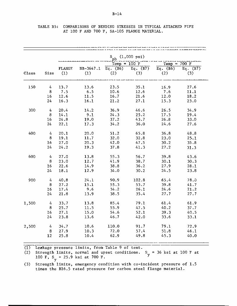
B-14
TABLE B5: COMPARISONS OF BENDING STRESSES IN TYPICAL ATTACHED PIPE
AT 100 F AND 700 F, SA-105 FLANGE MATERIAL.
Spb (1',000 psi)
FLANGE NB-3647.1
Temp == 100 F Temp = 700 F
Eq. (B6) Eq. (B7) Eq. (B6) Eq. (B7)Class Size (1) (1) (2) (3) (2) (3)
150 4 13.7 13.6 23.5 35.1 16.9 27.6
8 7.5 6.5 10.6 12.6 7.6 11.1
16 12.6 11.5 16.7 21.6 12.0 18.2
24 16.3 16.1 21.2 27.1 15.3 23.0
300 4 20.4 14.2 36.9 46.6 26.5 34.9
8 14.1 9.1 24.3 25.2 17.5 19.4
16 24.8 19.0 37.2 43.7 26.8 33.0
24 22.1 17.3 34.2 36.0 24.6 27.6
400 4 20.1 20.0 51.2 65.8 36.8 48.8
8 19.1 11.7 32.0 32.8 23.0 25.1
16 27.0 20.3 42.0 47.5 30.2 35.8
24 24.2 19.3 37.8 41.3 27.2 31.3
600 4 27.0 13.8 55.3 56.7 39.8 43.6
8 23.0 12.7 41.9 38.7 30.1 30.3
16 22.6 14.9 38.8 36.2 27.9 28.1
24 18.1 12.9 34.0 30.2 24.5 23.8
900 4 40.8 24.1 90.9 102.8 65.4 78.0
8 27.2 15.1 55.3 53.7 39.8 41.7
16 17.4 9.6 34.2 26.1 24.6 21.2
24 21.8 13.9 38.5 35.4 27.7 27.7
1,500 4 33.7 13.8 85.4 79.1 61.4 61.9
8 25.7 11.5 55.9 47.5 40.2 37.7
16 27.1 15.0 54.6 52.1 39.3 40.5
24 23.8 13.6 46.7 42.0 33.6 33.1
2,500 4 34.7 10.6 110.0 91.7 79.1 72.9
8 27.9 10.3 72.0 57.4 51.8 46.1
12 25.8 10.4 62.9 49.8 45.3 40.0
(1) Leakage pressure limits, from Table 9 of text.(2) Strength limits, normal and upset conditions. S = 36 ksi at 100 F at
100 F, S = 25.9 ksi at 700 F. yy
(3) Strength limits, emergency condition with co-incident pressure of 1.5times the B16.5 rated pressure for carbon steel flange material.

B-15
Usually, the design pressure is somewhat less than the B16.5 rated pressure;
for such cases, Equation (B7) will tend to permit higher moments than
Equation (B6). However, the permissible moment for emergency conditions
will not exceed 1.8 times that for normal/upset conditions; this occurs
for Pfd = 0.
FAULTED CONDITIONS
NB-3656, by reference in Code Appendix F, states that the pressure
under faulted conditions shall not exceed 2.0 times the design pressure.
While this may be above the B16.5 test pressure, it is deemed acceptable
for B16.5 flanged joints both from a bolt strength and flange strength
standpoint. However, for both pressure and moment loadings, it is not
apparent that anything more liberal than Equation (B7) can be recommended.
While under faulted conditions, all that is required is that the flanged
joint restrict leakage enough to permit a safe shutdown, it is not apparent
to the authors what that permissible leakage rate might be and, if it were
known, how the permissible leakage rate could be correlated with the leakage
characteristics of flanged joints where yielding of the flanges might occur.
TORSIONAL MOMENTS
The discussion so far has concerned bending moments. Flanged joints
may also be subjected to torsional moments applied by the attached pipe. These
torsional moments are resisted by frictional forces between the flange faces
and the gasket. Large rotations would be prevented by contact between the
bolts and bolt holes but, because bolt diameters are 1/8" less than hole
diameters, we should not depend upon the bolt shear resistance when concerned
about leakage.
With a coefficient of friction y between flange faces and gasket, the
torque capacity M of a flanged joint is

B-16
2-rr
Mpt=J f.dF (B8)o
where dF is the torsional resistance per inch of gasket circumference,
and G is the gasket diameter. The unit axial force (lb/inch) on the gasket
is Sb2Ab/irG, and dF = p^^/ttG) (G/2) d<f>, where <j> is the co-ordinateangle. Accordingly:
V -/(!)' ttG
o
dcf> = (B9)
We want to compare equation (B5) with equation (B9). We note
that G <C, and S (at operating conditions) may be less than the preload
bolt stress of (assumed) 40,000 psi. For high loads at the gasket interface,
a coefficient of friction of u = 1/2 appears reasonable. If we assume that
G/C = 1/2 and use Sfe2 = 25,000 psi( the same S assumed for bendingmoment evaluation) then equation (B9) gives
V - i ' \ ' ^Pc \ =3125 c \ <B10>
Equation (B5) gives Mfg = 3125 C Afo (for S = 36 ksi) hence, insofar asleakage is concerned, we can apply the same limit to torsional moments
as for bending moments. The (S /36) factor is not needed for torsional
moments but, for simplicity, equation (B5) will be recommended for both
bending moments and torsional moments—considered separately. These can
be considered separately because the bending moment does not reduce the
total load on the gasket; it decreases the load on the tension side but
increases the load on the compression side.
For short time loadings, where we do not necessarily design to
prevent temporary gross leakage, we first observe that the assumptions that
G/C =0.5 and Sbl = 25,000 psi are quite conservative for most B16.5 flangedjoints and most operating conditions. G/C is more typically equal to about
0.7. For pressure loading only, sb2/sbl is m°re typically about 0.75, hence,if Sbl = 40,000 psi, Sb2 = 30,000 psi. With these more typical ratios,equation (B9) gives M = 5250 C^ in.-lb. This is almost as high as the

B-17
limit given by the analogous equation (B6) of Mf, = 6250 C A, in.-lb.
In addition, large movements are prevented by the bolts. If we assign
an allowable shear stress for the bolts of 13,000 psi, the torsional
moment capacity of the bolts alone is 13000 Ci/2 = 6250 C A^ in.-lb.
Accordingly, equation (B9) is deemed as a suitable limit for short-time
torsional moments as well as short-time bending moments.
Insofar as the authors are aware, no test data exists on the
torsional moment capacity of flanged joints. While the limits developed
in the preceding are deemed to be conservative, it would be highly
desirable to obtain some test data.


APPENDIX C
RECOMMENDED CODE REVISIONS


C-1
NB-3600
It is recommended that the NB-3600 portion be revised as follows:
(1) Change NB-3651.2 to read:
NB-3651.2 Piping Products for Which Stress Indices Are Not Available.
For analysis of flanged joints, see NB-3658. For other piping products for
which stress indices are not available, see NB-3680.
(2) Change NB-3647.1 to read:
NB-3647.1 Flanged Joints.
(a) Flanged joints manufactured in accordance with the standards listed in
Table NB-3132-1, as limited by NB-3612.1, shall be considered as meeting
the requirements of NB-3640.
(b) Flanged joints not included in Table NB-3132-1 shall be designed in
accordance with Article XI - 3000, including the use of the appropriate
allowable stress given in Table 1-7.
(3) Add a New Paragraph NB-3658 to Read as Follows:
NB-3658 Analysis of Flanged Joints
Flanged joints using flanges, bolting, and gaskets as specified in
ANSI B16.5 (1968) and using a bolt material having an S - value at 100 F not
less than 20,000 psi may be analyzed in accordance with the following rules or
in accordance with NB-3200. Other flanged joints shall be analyzed in accord
ance with NB-3200.
NB-3658.1 Design, Normal and Upset Conditions
(a) Bolting. The bolting shall meet the requirements of NB-3232. In addition,
the limitations given by Equations (15) and (16) shall be met.
M fs < 3125 (S /36)C Ab , (15)

where
where
C-2
M. = bending or torsional moment (considered separately)rs
applied to the joint due to weight, thermal expansion
of the piping, sustained anchor movements, relief valve
steady-state thrust, and other sustained mechanical loads,
in-lb. If cold springing is used, the moment may be
reduced to the extent permitted by NB-3672.8.
S = yield strength (ksi) of flange material at design
temperature (Table 1-2.2). The value of (S /36) shall
not be taken as greater than unity.
C = diameter of bolt circle, in.
A^ = total cross-sectional area of bolts at root of thread or
section of least diameter under stress, sq. in.
M d± 6250 (S /36) CAb , (16)
M = bending or torsional moment (considered separately) as
defined for M but including dynamic loadings, in-lb.
(b) Flanges. Flanges of ANSI B16.5 flanged joints meeting the requirements
of NB-3612.1 are not required to be analyzed under NB-3650. However,
the pipe-to-flange welds shall meet the requirements of NB-3652, NB-3653,
and NB-3654, using appropriate stress indices from Table NB-3683.2-1.
NB-3658.2 Emergency Conditions
(a) The pressure shall not exceed 1.5 times the design pressure.
(b) The limitation given by Equation (17) shall be met.
Mfd <[11250 ^ -(tt/16) D2 Pfd] C(S /36) , (17)

C-3
where
Df = outside diameter of raised face, in.
pfd = pressure (psi) during the emergency condition concurrent
with M£,.fd
Mf,, C, S , the limitation on (S /36) and A, are defined in
NB-3658.1(a).
(c) Pipe-to-flange welds shall be evaluated by Equation (9) of NB-3652,
using a stress limit of 2.25 S .m
NB-3658.3 Faulted Conditions
(a) The pressure shall not exceed 2.0 times the design pressure.
(b) The limitation given by Equation (17) of NB-3658.2(b) shall be met, where
Pf, and Mf, are pressures (psi) and moments (in-lb) occurring concurrently
during the faulted condition.
(c) Pipe-to-flange welds shall be evaluated by Equation (9) of NB-3652, using
a stress limit of 3.0 S .m
NB-3658.4 Testing Conditions. Analysis for Testing Conditions is not required.

C-4
NC-3600
It is recommended that the NC-3600 portion be revised as follows.
(1) NC-3651, Add:
(c) For analysis of flanged joints, see NC-3658.
(2) NC-3671.1, Delete Period After "NC-3647" and Add:
and NC-3658.
(3) NC-3673.5(a)
Change equation numbers: (12) to (15) and (13) to (16).
(4) NC-3673.5(b)
Change "Formulas (12) and (13)" to "Equations (15) and (16)".
(5) Change NC-3647.1 to Read:
NC-3647.1 Flanged Joints.
(a) Flanged joints manufactured in accordance with the standards listed
in Table NC-3132-1, as limited by NC-3612.1, shall be considered as
meeting the requirements of NC-3640.
(b) Flanged joints not included in Table NC-3132-1 shall be designed in
accordance with Article XI - 3000.
(6) Add a New Paragraph NC-3658 to Read as Follows:
NC-3658 Analysis of Flanged Joints
Flanged joints using flanges, bolting, and gaskets as specified in
ANSI B16.5 (1968) and using a bolt material having an S - value at 100 F not
C-5
less than 20,000 psi may be analyzed in accordance with the following rules or
in accordance with NB-3200. Other flanged joints shall be analyzed in accordance
with NB-3200. If the NB-3200 analysis is used, allowable stresses from Table
1-7 and 1-8 shall be used in place of S .m
NC-3658.1 Design, Normal and Upset Conditions
(a) The limitations given by Equations (12) and (13) shall be met.
where
Mfs
C
M :, < 3125 (S /36) C A, ,fs — y o
(12)
bending or torsional moment (considered separately)
applied to the joint due to weight, thermal expansion
of the piping, sustained anchor movements, relief valve
steady-state thrust and other sustained mechanical loads,
in-lb. If cold springing is used, the moment may be
reduced to the extent permitted by NC-3673.5.
yield strength (ksi) of flange material at design tempera
ture (Table 1-2.2). The value of (S /36) shall not be
taken as greater than unity,
diameter of bolt circle, in.
total cross-sectional area of bolts at root of thread or
section of least diameter under stress, sq. in.
M <. 6250 (S /36) C A^ (13)
where
M_, = bending or torsional moment (considered separately) asfd
defined for M- but including dynamic loadings, in-lb.
(b) Flanges. Flanges of ANSI B16.5 flanged joints meeting the require
ments of NC-3612.1 are not required to be analyzed under NC-3650.
However, the pipe-to-flange welds shall meet the requirements of
NC-3652, using appropriate stress intensification factors from
Figure NC-3673.2(b)-l.

C-6
NC-3658.2 Emergency Conditions
(a) The pressure shall not exceed 1.5 times the design pressure.
(b) The limitation given by Equation (14) shall be met.
Mfd <[11250 A^ -(tt/16) D2 Pfd] C(S /36) , (14)
where
Df = outside diameter of raised face, in.
Pf, = pressure (psi) during the emergency condition concurrent
with M^-j.id
Mf,, C, S , the limitation on (S /36) and A, are defined in
NC-3658.1(a).
(c) Pipe-to-flange welds shall be evaluated by Equation (9) of NC-3652,
using a stress limit of 1.8 S .
NC-3658.3 Faulted Conditions
(a) The pressure shall not exceed 2.0 times the design pressure.
(b) The limitation given by Equation (14) shall be met, where Pfd
and M_, are pressures (psi) and moments (in-lb) occurring concurrentlyid
during the faulted condition.
(c) Pipe-to-flange welds shall be evaluated by Equation (9) of NC-3652,
using a stress limit of 2.4 S, .
NC-3658.4 Testing Conditions. Analysis for Testing Conditions is not required.
ND-3600
It is recommended that ND-3600 be changed as shown for NC-3600;
changing NC to ND in all places where NC occurs. In ND-3673.5, the present
equation numbers (9) and (10) are to be changed to (15) and (16) in two places.
Do not change the phrase: "using Equations (9) and (10) (ND-3650).".
![· 2010-10-27 · BARSANESCU , Stefan. Unitatea pedagogiei" contemporane stiintä. ]3UZÁS Lász1ó.Activitatea didacticä pe grupe. 1976. 1976. 1976. 1976. ca 1976 1976. RIVïRS,Ti1ga-ll](https://img.dokumen.tips/doc/110x75/5e65a6b2340ac244f46daed1/2010-10-27-barsanescu-stefan-unitatea-pedagogiei-contemporane-stiint.jpg)


