Embed Size (px)
Citation preview
SYMPOSIUM SERIES NO. 156 Hazards XXII # 2011 Crown Copyright
FLAMMABILITY OF HYDROCARBON/CO2 MIXTURES: PART 1. IGNITION ANDEXPLOSION CHARACTERISTICS†
Pursell, M.R.1, Gant, S.E.1, Fletcher, J.1, Rattigan, W.1, Thyer, A.M.2, Connolly, S.2
1Health & Safety Laboratory, Buxton, UK2Health & Safety Executive, Bootle, Merseyside, UK
The next decade is likely to see a rapid increase in the transport offshore of carbon dioxide (CO2)
for enhanced oil recovery and sequestration of the material into depleted oil and gas fields. As a
result hydrocarbon gas streams may become increasingly contaminated by CO2, and indeed, it
may even sometimes be advantageous to mix the two streams to reduce the hazard posed by
fires and explosions from unintended releases. As a result, risk assessments may therefore need
to incorporate consequence modelling which takes into account the presence of CO2 and the
new/modified hazards including changes in fire and explosion properties, and the risk of asphyx-
iation. The present work examines the effect of CO2 concentration on the ignition of hydrocarbon
and CO2 gas mixtures in jet releases and explosions in confined spaces.
A previous study investigated the inerting potential of CO2 and N2 with respect to propane and
hydrogen gas releases (Thyer et al., 2009). The present work extends that study to examine the
effect of release velocity and CO2 concentration on the ignition of methane releases. Additionally
the explosivity of CO2/methane mixtures was examined in a 20 litre explosion sphere and an 8 m
long section of 1.04 m diameter pipeline.
Increasing concentrations of CO2 were found to reduce the likelihood of ignition of a methane jet
release. Up to CO2 concentrations of 22–40% (v/v) it was possible for a self-sustaining flame to
exist, but beyond these concentrations a pilot flame was required to aid combustion. Beyond
60% CO2 the pilot flame had no effect and the mixture was completely inert. The release velocity
was also found to influence the ignition characteristics, with high-velocity releases requiring
a lower concentration of CO2 to affect the ignition behaviour. This is due to the effect of CO2
on reducing the flame front speed leading to flame blow out.
Explosion tests performed in the small explosion sphere and a larger 8 m section of pipeline
displayed similar characteristics. In both situations increasing the concentration of CO2 led to a
reduction in the explosion overpressure. In the explosion sphere the CO2/methane mixtures
were found to be ignitable up to a CO2 feed concentration of 60%. In the pipeline explosions,
mixtures of 28.2% and 40% CO2 were ignitable, whereas at 59% CO2 ignition did not occur.
INTRODUCTIONThe next decade is likely to see a rapid increase in the trans-port offshore of carbon dioxide (CO2) for enhanced oilrecovery and sequestration into depleted oil and gas fields.As a result, hydrocarbon gas streams may become increas-ingly contaminated by CO2, and indeed it may sometimesbe advantageous to mix the two streams to reduce thehazard posed by fires and explosions from unintendedreleases. Risk assessments may therefore need to incorpor-ate consequence modelling that takes into account the pres-ence of CO2 and the new or modified hazards, includingchanges in fire and explosion properties. In addition tothese considerations, ageing offshore installations are alsonow being decommissioned or dismantled at an increasingrate. Dismantling of poorly-inerted former hydrocarbonprocessing plant has been known to cause fires andexplosions resulting in fatalities. To help provide informa-tion to both regulatory bodies and industry on the hazardsposed by mixtures of hydrocarbon and inert gases, thepresent work examines the flammability of premixed andnon-premixed hydrocarbon and CO2 gas mixtures.
440
Premixed explosion tests were performed on twoscales. The first being on a smaller scale in a 20 litreexplosion sphere that is a standard test used to assess theexplosion properties of materials. The second type werelarger tests performed in a 8 m section of 1.04 m diameterpipe, which had a total volume of 6.8 m3. In both casesthe mixtures of methane (CH4) and carbon dioxide (CO2)were examined with the methane concentration in theregion of the stoichiometric concentration (9.5%) andoverall CO2 concentrations varying between 0 and 20%.Additionally mixtures of propane and CO2 were examinedin the smaller 20 litre sphere.
Two categories of diffusion flame (non premixed)ignition tests were performed. The first were bulk ignitiontests using a large ignition source (propane blow torch).These were done to assess the limits of the CO2 inertingeffect on methane. The second category of tests weredetailed ignition probability tests performed on a 100% v/v CH4 and a 80/20% v/v CH4/CO2 non premixed gas jetmixtures. The results from these tests are presented in acompanion paper that investigates an empirically-based
†# Crown Copyright 2011. This article is published with the permission of the Controller of HMSO and the Queen’s Printer for Scotland.

SYMPOSIUM SERIES NO. 156 Hazards XXII # 2011 Crown Copyright
mathematical model for the ignition probability in free-jets(Gant et al., 2011).
BACKGROUNDThere are numerous studies on the effect of inerting gaseson the flammability envelope for fuel gases. Generallythese studies have used one of the standard test procedures(ASTM, ISO or DIN) and the prescribed apparatus to deter-mine the upper and lower concentrations where flamepropagation will occur. When determining the role of CO2
(or other additives) in inerting hydrocarbon mixtures theexperimental mode of investigation can have a significantbearing on the observed flammability behaviour, with differ-ent flammability limits being observed when experimentswere conducted with premixed flames or diffusion jetflames (Beyler, 1988). Furthermore there can be significantdifferences in behaviour when considering gas cloud com-bustion versus a jet or pressurised release. In the later casethe mixing of the release with atmosphere will result in anoxygen gradient through the release, giving rise to a flam-mable/ignitable zone.
The flammability limits of methane and the effectof inert gases have been studied on many occasions (e.g.Zabetakis, 1965). A recent example is the study of Kondoet al. (2006) which examined flammability limits anumber of hydrocarbons (methane, propane, ethylene, pro-pylene, methyl ether, methyl formate, 1,1-difluoroethane,and ammonia) with different quantities of CO2 present. Itthat work they used an explosion bomb similar to thatdescribed in ASTM E681 for determination of the concen-tration limits of flammability. It was found that increasingthe CO2 concentration decreased the flammability window,and it was projected that the inertisation point occurred ata CO2 feed mole fraction of 0.794 (which corresponds toca 25% v/v in the stoichiometric air/fuel/inert mixture).Thyer et al. (2008) investigated the inerting effect of CO2
and N2 on the ignition behaviour of propane and hydrogenfor diffusion jets. Figure 1 (taken from Thyer et al., 2008)shows the results obtained for experiments with propane
441
and CO2. Based on the trend of the experimental results itwas estimated that complete inerting would occur in theregion of 90% CO2 feed concentration. A detailed studyof the ignition probability of diffusion flames was under-taken by Birch and co-workers at the British Gas researchstation (Birch et al. 1981, Smith et al. 1988, Birch et al.1989). They studied the effect of ignition location on theprobability of ignition for turbulent jets of methane, towngas and propane. The ignition source was an inductivespark system. The ignition probability was highest inregions corresponding to the stoichiometric concentration,however ignition was still possible in regions outside themean flammability limit window due to turbulent fluctu-ations in the local fuel concentration. Birch et al. (1981)produced contour maps showing regions of ignition pro-bability. Ahmed and Mastorakos (2006) examined sparkignition of turbulent methane diffusion jets, characterisingthe factors that affect ignition. High jet velocities werefound to reduce the ignition probability due to convectiveheat loss from the spark in the early stages of the ignitionprocess.
These studies highlight the difference in behaviourwhen examining ignition via different methods. Whenconsidering the flammability of jet releases of hydro-carbon/inert mixtures the limits determined in a staticcombustion test may not give complete guidance on thepotential behaviour. In static tests adequate reduction ofthe oxygen content/ratio may render the system inert,however during release into the atmosphere the subsequentaddition of air to the system may result in a flammablemixture. The release properties, the ignition source and itslocation relative to the release point will have importantconsequences on the flammable region.
EXPERIMENTAL SETUP
EXPLOSION STUDIES
20 Litre Explosion SphereA series of small-scale explosion experiments were carriedout to determine the explosion behaviour of mixtures of
0 % propane100% CO2
x
20 % propane 80% CO2
40 % propane 60% CO2
60 % propane40% CO2
80 % propane 20% CO2
No effect
Enhanced combustion of pilot flame
Cannot burn without pilot flame
Burns for decreasingperiod
Flame unstable
Flame stable andpersistent
100 % propane 0% CO2
xx
xx
x
Possible location of theoretical point where a mixture cannot undergo combustion ?
O
Figure 1. Illustrative graph showing changes in combustion stability as a function of propane/CO2 concentrations (from Thyer
et al., 2008)
SYMPOSIUM SERIES NO. 156 Hazards XXII # 2011 Crown Copyright
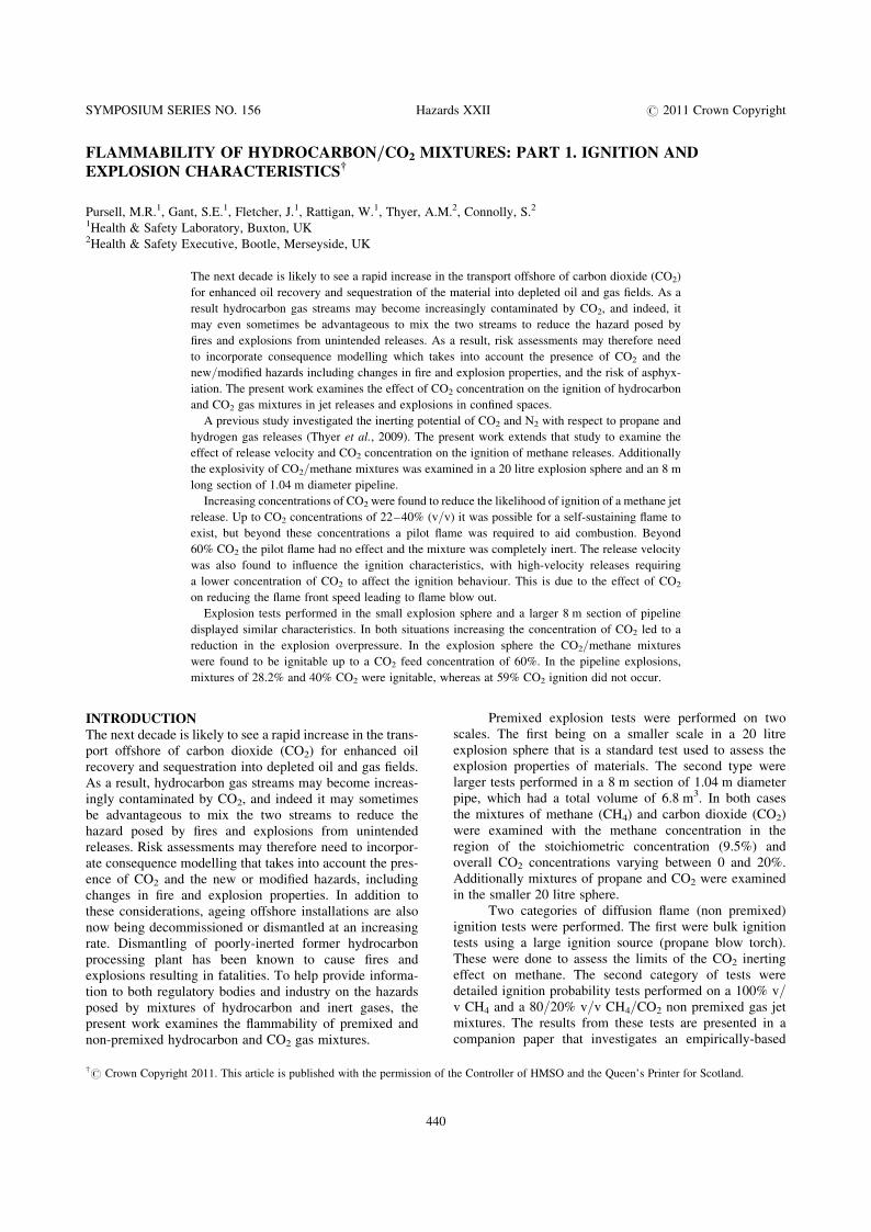
Figure 2. Photograph of (a) the 1.04 m diameter explosion vessel and (b) the 34
open relief vent
hydrocarbon (methane or propane) with CO2 and air. Thetests were performed in a standard 20 litre explosionsphere in accordance with the principles of British Standard,BS EN 1839:2003 Determination of explosion limits ofgases and vapours. The vessel was first evacuated to�100 mbar absolute before the hydrocarbon, CO2 and airgases were introduced to the vessel via a manifold. Thequantities of each substance were measured by partialpressure readings using a high precision digital pressuregauge. The vessel temperature was maintained at 25oC byusing heating fluid around the vessel jacket. The ignitionof the atmosphere was effected using a 10 kV spark genera-tor across two stainless steel electrode tips. Control ofthe ignition system was via a computer linked to the sparkgenerator unit, an interlock on the fume cupboard sashpreventing accidental activation of the spark generator.The explosion overpressures was recorded using two cali-brated Kistler (type 701A) pressure transducers; the datalogged at 50 kHz. Overall methane and propane con-centrations were 10% and 5% respectively, with the CO2
concentration being varied between 0% and 20%. Thiscorresponds to CO2/fuel feed concentrations of 0 to 80%.
1.04 m Diameter PipelineLarger gas explosions were conducted in a facility designedto test the explosion resistance of passive fire protection
44
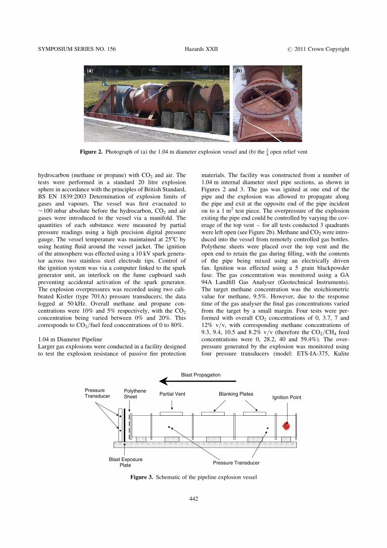
materials. The facility was constructed from a number of1.04 m internal diameter steel pipe sections, as shown inFigures 2 and 3. The gas was ignited at one end of thepipe and the explosion was allowed to propagate alongthe pipe and exit at the opposite end of the pipe incidenton to a 1 m2 test piece. The overpressure of the explosionexiting the pipe end could be controlled by varying the cov-erage of the top vent – for all tests conducted 3 quadrantswere left open (see Figure 2b). Methane and CO2 were intro-duced into the vessel from remotely controlled gas bottles.Polythene sheets were placed over the top vent and theopen end to retain the gas during filling, with the contentsof the pipe being mixed using an electrically drivenfan. Ignition was effected using a 5 grain blackpowderfuse. The gas concentration was monitored using a GA94A Landfill Gas Analyser (Geotechnical Instruments).The target methane concentration was the stoichiometricvalue for methane, 9.5%. However, due to the responsetime of the gas analyser the final gas concentrations variedfrom the target by a small margin. Four tests were per-formed with overall CO2 concentrations of 0, 3.7, 7 and12% v/v, with corresponding methane concentrations of9.3, 9.4, 10.5 and 8.2% v/v (therefore the CO2/CH4 feedconcentrations were 0, 28.2, 40 and 59.4%). The over-pressure generated by the explosion was monitored usingfour pressure transducers (model: ETS-IA-375, Kulite
Pressure Transducer Blanking Plates
Polythene Sheet
Blast Exposure Plate
Blast Propagation
Partial Vent
Pressure Transducer
Ignition Point
Figure 3. Schematic of the pipeline explosion vessel
2

SYMPOSIUM SERIES NO. 156 Hazards XXII # 2011 Crown Copyright
Semiconductor Products). Two 0–17 barg pressure transdu-cers were mounted at either end of the pipe, and two 0–7barg pressure transducers were mounted in the test plate.Data was logged using a high speed data logger (DewiSoftv7.0) at a sampling rate of 50 kHz.
IGNITION STUDYMethane and CO2 gases were provided from gas cylindersregulated to 3 bar. Each gas was connected through a rota-meter with a manual flow controller allowing flowratesbetween 10 and 90 l/min. Following the rotameters thegases were combined at a T-junction, and then a shut offvalve. The shut off valve allowed the total gas flow to bestopped immediately without adjusting the flow settings.The shut off valve was connected to the release nozzle via5 metres of fire resistant gas tubing. The release nozzlehad dimensions of 6 mm ID, 8 mm OD, and 400 mmlength. The nozzle was attached vertically to a metalframe. Ignition was effected using a propane blowtorch.All experiments were performed in a sheltered courtyardthat allowed experiments to be performed in moderatelystill weather conditions. The bulk ignition characteristicswere examined at 3 different total flowrates (30, 50 and90 l/min), details of the corresponding exit velocities andReynolds numbers are given in Table 1.
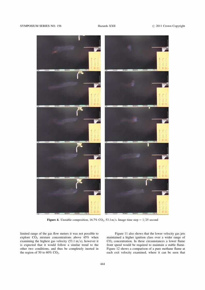
The tests were categorised based on the response ofthe gas mixture to the ignition flame, in a similar mannerto the study of Thyer et al. (2009), see Table 2. For Classes1, 2, and 3 the blowtorch flame was kept in the gas jet,whereas for Classes 4 and 5 the flame was removed assoon as ignition occurred. Figure 4 shows an example of aClass 3 ignition for a gas mixture containing 16.7% v/vCO2 with a release velocity of 53.1 m/s. Each image is asequential frame recorded at 25 frames per second. In theinitial frames it is seen that the gas burns in the presenceof the pilot flame, however once this is removed the flamefront is blown downstream and extinguished.
Table 1. Experimental release conditions
Volumetric flow rate (l/min) 30 50 90
Exit velocity (m/s) 17.7 29.5 53.1
Reynolds number� 6453 10755 19359
�For 100% CH4
Table 2. Ignition response classifications
Class Ignition response
1 No effect on pilot flame
2 Enhances combustion of pilot flame
3 Burns only in the presence of the pilot flame
4 Burns for a short period
5 Stable combustion, burns continuously
44
Ignition tests were recorded using a HDC-SD10 videocamera (Panasonic) that recorded at 25 fps. Individualframes/images were captured using the HD Writer AEv1.5 (Panasonic). The image analysis software ImageJwas used to determine the flame lift off distances.
RESULTS & DISCUSSION
EXPLOSION STUDIES
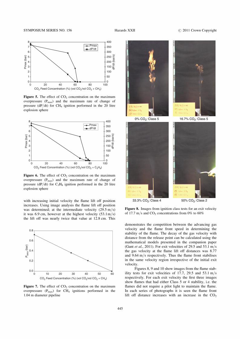
20 Litre Explosion SphereFigures 5 and 6 present the results of the explosions testsperformed in the 20 litre explosion sphere, for methaneand propane respectively. To allow comparisons with thenon premixed ignition tests the results are present in termsof a ‘feed’ concentration of CO2 and fuel gas. It wasfound for both gases that increasing the CO2 concentrationcaused a decrease in both the maximum overpressure(PMax), and the rate of change of pressure (dP/dt). It isnotable for both gases that the rate of change of pressurewas greatly reduced in all tests where CO2 was present.For methane the maximum ignitable concentration was60%, and for propane the concentration was 78%, how-ever at this level only a slight overpressure was recorded.The reduction in the PMax and dP/dt due to the additionof CO2 will be due to a reduction in the flame speed.
1.04 m Diameter PipelineThe effect of CO2 feed concentration on the large-scale gasexplosions are presented in Figure 7. Increasing the CO2
concentration caused a decrease in the maximum overpres-sure recorded. At a CO2 feed concentration of 59.4% noignition of the gas mixture occurred. These results are com-parable to results obtained for methane ignitions in thesmaller 20 litre explosion sphere where a reduction in over-pressure was recorded with increasing CO2 concentration.However, in the 20 litre explosion sphere ignition wasdetected at slightly higher CO2 concentrations. The testsconducted in the 20 litre explosion sphere were morecontrollable with more certain mixing of the gas prior toignition. Given the larger volume involved in the 1.04 mpipe tests (8.3 m3) there is the possibility of incompletemixing. Thus there is the possibility of failed ignition eventhough the mean concentration in the pipe was ignitable.
IGNITION CHARACTERISTICS OF CH4/CO2
MIXTURESThe bulk ignition behaviour of CH4/CO2 gas mixtures wasexamined at three different exit velocities, and at CO2 con-centrations up to 70%. Still images for each condition arepresented in Figures 8, 9 and 10. The ignition responsewas classified according to Table 2. Figure 11 summarisesthe change in the ignition response class with changingCO2 concentration, for the three different exit velocities.For all the gas velocities examined, the ignition responsedecreased with increasing CO2 concentration. For gasvelocities of 29.5 m/s and 17.7 m/s the methane was com-pletely inerted at CO2 concentrations above 60%. Due to the
3
SYMPOSIUM SERIES NO. 156 Hazards XXII # 2011 Crown Copyright
Figure 4. Unstable composition, 16.7% CO2, 53.1m/s. Image time step ¼ 1/25 second
limited range of the gas flow meters it was not possible toexplore CO2 mixture concentrations above 45% whenexamining the highest gas velocity (53.1 m/s), however itis expected that it would follow a similar trend to theother two conditions, and thus be completely inerted inthe region of 50 to 60% CO2.
444
Figure 11 also shows that the lower velocity gas jetsmaintained a higher ignition class over a wider range ofCO2 concentration. In these circumstances a lower flamefront speed would be required to maintain a stable flame.Figure 12 shows a comparison of a pure methane flame ateach exit velocity examined, where it can be seen that
SYMPOSIUM SERIES NO. 156 Hazards XXII # 2011 Crown Copyright
with increasing initial velocity the flame lift off positionincreases. Using image analysis the flame lift off positionwas determined; at the intermediate velocity (29.5 m/s)it was 6.9 cm, however at the highest velocity (53.1m/s)the lift off was nearly twice that value at 12.8 cm. This
0
1
2
3
4
5
6
7
8
0 20 40 60 80 100CO2 Feed Concentration (%) (vol CO2/vol CO2 + CH4)
Pm
ax (
bar)
0
50
100
150
200
250
300
350
400
dP/d
t (ba
r/s)
PmaxdP/dt
Figure 5. The effect of CO2 concentration on the maximum
overpressure (Pmax) and the maximum rate of change of
pressure (dP/dt) for CH4 ignition performed in the 20 litre
explosion sphere
0
1
2
3
4
5
6
7
8
0 20 40 60 80 100CO2 Feed Concentration (%) (vol CO2/vol CO2 + C3H8)
Pm
ax (
bar)
0
50
100
150
200
250
300
350
400
dP/d
t (ba
r/s)
PmaxdP/dt
Figure 6. The effect of CO2 concentration on the maximum
overpressure (Pmax) and the maximum rate of change of
pressure (dP/dt) for C3H8 ignition performed in the 20 litre
explosion sphere
0.0
0.2
0.4
0.6
0.8
0 10 20 30 40 50 60
CO2 Feed Concentration (%) (vol CO2/vol CO2 + CH4)
PM
AX (
bar)
Figure 7. The effect of CO2 concentration on the maximum
overpressure (Pmax) for CH4 ignitions performed in the
1.04 m diameter pipeline
445
demonstrates the competition between the advancing gasvelocity and the flame front speed in determining thestability of the flame. The decay of the gas velocity withdistance from the release point can be calculated using themathematical models presented in the companion paper(Gant et al., 2011). For exit velocities of 29.5 and 53.1 m/sthe gas velocity at the flame lift off distances was 8.77and 9.64 m/s respectively. Thus the flame front stabilisesin the same velocity region irrespective of the initial exitvelocity.
Figures 8, 9 and 10 show images from the flame stab-ility tests for exit velocities of 17.7, 29.5 and 53.1 m/srespectively. For each exit velocity the first three imagesshow flames that had either Class 5 or 4 stability, i.e. theflames did not require a pilot light to maintain the flame.In each series of photographs it is seen the flame frontlift off distance increases with an increase in the CO2
0% CO2: Class 5 16.7% CO2: Class 5
33.3% CO2: Class 4 50% CO2: Class 2
Figure 8. Images from ignition class tests for an exit velocity
of 17.7 m/s and CO2 concentrations from 0% to 60%

SYMPOSIUM SERIES NO. 156 Hazards XXII # 2011 Crown Copyright
0% CO2: Class 5 10% CO2: Class 5 20% CO2: Class 4
30% CO2: Class 3 40% CO2: Class 2 50% CO2: Class 2
60% CO2: Class 1
Figure 9. Images from ignition class tests for an exit velocity of 29.5 m/s and CO2 concentrations from 0% to 60%
446

SYMPOSIUM SERIES NO. 156 Hazards XXII # 2011 Crown Copyright
0% CO2: Class 5 5.6% CO2: Class 5 11.1% CO2: Class 4
16.7% CO2: Class 3 22.2% CO2: Class 3 27.8% CO2: Class 3
33.3% CO2: Class 2 44.4% CO2: Class 2
Figure 10. Images from ignition class tests for an exit velocity of 53.1 m/s and CO2 concentrations from 0% to 44.4%
447

SYMPOSIUM SERIES NO. 156 Hazards XXII # 2011 Crown Copyright
concentration. Therefore the flame front velocity deceasesas the concentration of CO2 increases. Beyond the thresholdconcentrations of 33.3%, 20% and 11.1%, for exit velocitiesof 17.7, 29.5 and 53.1 m/s respectively, it was not possibleto maintain a stable flame. Above these concentrations theflame front velocity that could have been generated any-where in the gas stream will have been lower than thelocal velocity in the jet, thus blow out of the flame occurred.The addition of CO2 to the fuel mixture will have the effectof changing the calorific value of the fuel mixture leading toa reduction in the reaction rate and flame speed. Ishizukaand Tsuji (1981) examined the effect of inert gases onflame stability in countercurrent diffusion flames. Theyfound a limiting inert concentration beyond which a stableflame could not be maintained, which they attributed tochemical limitations on the combustion rate. They alsoobserved that the flame temperature decreased as the inertconcentration in the fuel mixture was increased. Similarlyin the 20l explosion sphere tests presented earlier the
1
2
3
4
5
0 20 40 60 80CO2 Feed Concentration (%) (vol CO2/vol CO2 + CH4)
Igni
tion
Res
pons
e C
lass
53.1 m/s
29.5 m/s
17.7 m/s
Figure 11. The change in ignition response class of gas
mixtures with CO2 over the range 0–70%, for exit gas
velocities of 17.7, 29.5 and 53.1 m/s
448
reduction in Pmax and dP/dt with increasing CO2 concen-tration are indicative of a reduction in the flame speed.
The current results demonstrate that hydrocarbonlines containing CO2 can still give rise to combustiblemixtures when unintended releases occur. The concen-trations identified in Figure 8 occur at levels at or belowthose determined in the explosions tests (Figure 5), thereforestatic tests provided conservative values that should beobserved.
CONCLUSIONSIt has been shown that the addition of CO2 has an effecton the ignition of methane and propane when bothpremixed and diffusive fuel-air mixtures are considered.Increasing the concentration of CO2 reduces the over-pressure obtained from explosion tests. In well-controlledsmall-scale explosions methane was inerted at a CO2 feedconcentrations above 60%, and for propane above 78%. Inlarger scale methane explosion tests the limiting CO2 feedconcentration was found to be 59.4%. Investigations ofignition of diffusing methane and CO2 mixtures showedthat stable combustion was possible up to CO2 thresholdconcentrations of 33.3%, however the stability of theflame was also influenced by the fuel gas exit velocity.Above the stability threshold enhancement of the ignitionsource occurred and complete inerting did not occur untilthe mean CO2 concentration reached 60–70%. In relationto process safety, care should be taken when inerting hydro-carbons lines as accidental releases may still result incombustible mixtures.
ACKNOWLEDGEMENTSThis publication and the work it describes were fundedby the Health and Safety Executive (HSE). Its contents,including any opinions and/or conclusions expressed, are
17.1 m/s 29.5 m/s 53.1 m/s
(c)(b)(a)
Figure 12. Comparison of the pure methane flames at different exit velocities

SYMPOSIUM SERIES NO. 156 Hazards XXII # 2011 Crown Copyright
those of the authors alone and do not necessarily reflectHSE policy.
REFERENCESAhmed, S.F., and Mastorakos, E., 2006, Spark ignition of lifted
turbulent jet flames, Combustion and Flame, 146: 215–231.
Beyler, C., 1988, Flammability limits of premixed and diffusion
flames, SFPE Handbook of Fire Protection Engineering.
Birch, A.D., Brown, D.R., and Dodson, M.G., 1981, Ignition
probabilities in turbulent mixing flows, 18th Symposium
(International) on Combustion, The Combustion Institute,
1775–1780.
Birch, A.D., Brown, D.R., Fairweather, M., and Hargrave,
G.K., 1989, An Experimental Study of a Turbulent Natural
Gas jet in a Cross-Flow, Combustion Science and Technol-
ogy, 6: 217–232.
Gant, S.E., Pursell, M.R., Lea, C.J., Thyer, A.M., and Connolly,
S., Flammability of Hydrocarbon/CO2 Mixtures: Part 2. Pre-
dictive Models for Gas Jet Ignition, Submitted to IChemE
Hazards XXII Conference, Liverpool, UK, 11–14 April 2011.
449
Ishizuka, S., and Tsuji, H. 1981, An experimental study of
effect of inert gases on extinction of laminar diffusion
flames, 18th Symposium (International) on Combustion,
The Combustion Institute, 695–703.
Kondo, S., Takizawa, K., Takahashi, A., and Tokuhashi, K.,
2006, Extended Le Chatelier’s formula for carbon dioxide
dilution effect on flammability limits, Journal of Hazardous
Materials, 138: 1–8.
Smith, M.T.E., Birch, A.D., Brown, D.R., and Fairweather, M.,
1988, Studies of ignition and flame propagation in turbulent
jets of natural gas, propane and a gas with a high hydrogen
content, 21st Symposium (International) on Combustion,
The Combustion Institute, 1403–1408.
Thyer, A.M., Kay, J., and Gant, S.E., 2009, Investigations into
the flammability of propane/carbon dioxide, hydrogen/carbon dioxide and hydrogen/nitrogen mixtures, IChemE
Hazards XXI Conference, Manchester, UK, 9–12 November
2009.
Zabetakis, M.G., Flammability Characteristics of Combus-
tible Gases and Vapors: Bulletin 627, Bureau of Mines,
Washington DC, 1965.