Embed Size (px)
Citation preview

Fixed Access Unit (FAU)for Globalstar Systems
FAU200 SAT
Installation HandbookREF.PARTNUMBER:FAU-200-GUIDE

Globalstar FAU-200 Package Contents
Thank you for purchasing the Globalstar FAU-200 fixed access unit. The FAU-200 enables an end user to make and receive telephone calls via the Globalstar satellite network.
Your FAU-200 package should contain the following items.
1 FAU Module complete with two 16 mm bolts
1 EF-I200 Installation Kit (Kit includes a power supply, AC power cord, 1 FAU power connector, and 1 FAU telephone connector)
1 50 Foot Power Cable
1 Telephone Interface (NID) Box
1 NTM201 2279 Mounting Kit
1 LZT 123 5327 User Documentation Package
1 TX Antenna and O Ring
1 RX Antenna and O Ring
2 Rear Sunshields
1 FAU-200-Guide Installation Handbook

The product described in this manual conforms to the 98/13/EC Telecommunications Terminal Equipment (TTE) and Satellite Earth Station Equipment (SESE) Directive, the 89/336/EEC EMC Directive and the 73/23/EEC Low Voltage Directive.
This device complies with part 15 of the FCC Rules. Operation is subject to the following two conditions: (1)This device may not cause harmful interference, and (2) this device must accept any interference received,including interference that may cause undesired operation.
First Edition: April 2000
This manual is published by Globalstar L.P. “AS IS” WITHOUT ANY WARRANTY. Improvements andchanges to this manual required by typographical errors, inaccuracies, or improvements to programs and /or equipment, may be made by Globalstar LP, at any time and without notice. Such changes will, however,be incorporated into new editions of this manual.
Publication number: EN/LZT 123 5050 R2
FAU Installation Handbook
c
SAFETY
Warnings
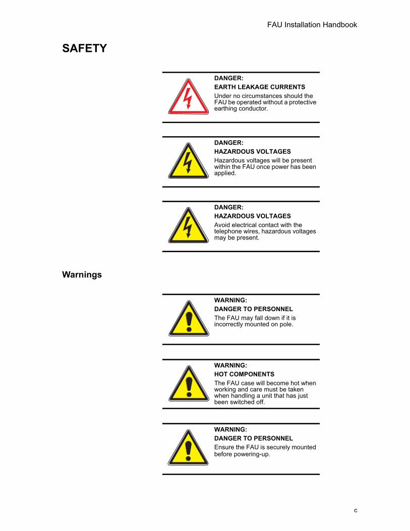
DANGER: EARTH LEAKAGE CURRENTSUnder no circumstances should the FAU be operated without a protective earthing conductor.
DANGER: HAZARDOUS VOLTAGESHazardous voltages will be present within the FAU once power has been applied.
DANGER:HAZARDOUS VOLTAGESAvoid electrical contact with the telephone wires, hazardous voltages may be present.
WARNING:DANGER TO PERSONNELThe FAU may fall down if it is incorrectly mounted on pole.
WARNING:HOT COMPONENTSThe FAU case will become hot when working and care must be taken when handling a unit that has just been switched off.
WARNING:DANGER TO PERSONNELEnsure the FAU is securely mounted before powering-up.

FAU Installation Handbook
i
ContentsGeneral ............................................................................................. 1
Definitions and Abbreviations .............................................................................1
Product Description ........................................................................ 2Globalstar System ................................................................................................2Fixed Access Unit (FAU) ....................................................................................2
Pre-Installation ................................................................................. 3Pre-Installation Planning ......................................................................................3
Planning the Location for the FAU ................................................................4Radio Interference Sources (for Guidance Only) ...........................................5Cable Routing .................................................................................................5Lightning Protection .......................................................................................6Switched DC Power Supply ............................................................................6Pole Mounting ................................................................................................7
Preparatory field engineering work .....................................................................7Preparation and Configuration of the FAU ..........................................................7
Installation ....................................................................................... 9Assembling the FAU ...........................................................................................9Fitting the FAU ..................................................................................................10FAU Connections ..............................................................................................12
Telephone ( ) .............................................................................................13Power ( ) ...................................................................................................13
PDI ( ) ......................................................................................................14SAFETY - Earth/Ground and NID Box Installation..................................14 - 18
Commissioning 19Power-Up ...........................................................................................................19Making a test call ...............................................................................................19Receiving an Incoming Test Call .......................................................................19
Reset Functions ..................................................................................................20
Fault Finding ......................................................................................................21
Technical Data - FAU .....................................................................22Physical ..............................................................................................................23Power requirements ...........................................................................................23Environmental ....................................................................................................23Interfaces 23
Air interface ..................................................................................................23Installation .........................................................................................................24Standards ............................................................................................................24
Technical Data - Cables .....................................................................................24Cable between FAU and PSU ......................................................................24Cable between FAU and cross-connect ........................................................25Protective Earth Cable (typical) ...................................................................25Additional Information .................................................................................25Patent..............................................................................................................26

FAU Installation Handbook
ii
APPENDIX 27Additional Cable Information and Typical Installation Details
Additional Specifications for Cables and ConnectorsTypical Wall and Pole Mounting of the FAU

FAU Installation Handbook
1
GeneralThe FAU is a device to enable the end user to make and receive telephone calls viathe Globalstar satellite network. This handbook describes how to plan theinstallation, fit the FAU and prepare it for use. Please read the safety informationcarefully. This issue covers the residential and PABX versions of the FAU only.
Definitions and AbbreviationsAC Alternating CurrentACB All Circuits BusyANSI American National Standards InstituteAWG American Wire GaugeBTS Base Transmitting StationCHS Circular Hollow SectiondB DecibelsdB/K Decibels per degree KelvindBm Decibel referred to 1 mWDC Direct CurrentDTMF Dual Tone Multi-FrequencyEIA Electronic Industries AssociationEIRP Effective Isotropic Radiated PowerFAU Fixed Access Unit for Globalstar networkGAI Globalstar Air InterfaceHz HertzIP Ingress ProtectionITU International Telecommunications UnionLEO Low Earth OrbitLNA Low Noise AmplifierNm Newton-metresP(A)BX Private (Automatic) Branch ExchangePDI Production & Development InterfacePIN Personal Identity NumberPSTN Public Switched Telephone NetworkREN Ringer Equivalence NumberRMS Root Mean SquareSIM Subscriber Identity ModuleTIA Telecommunications Industry AssociationTTE Telecommunications Terminal EquipmentWM2 A PC-based Windows software tool for testing and configuring the FAU

FAU Installation Handbook
2
Product DescriptionGlobalstar System
Globalstar is a low earth orbit (LEO) satellite-based telecommunications networkoffering wireless telephone services worldwide. The Fixed Access Unit (FAU)provides an interface for the end-user to access the Globalstar satellite network.The FAU communicates using the Globalstar Air Interface (GAI) via the satelliteconstellation to a number of groundstations or Gateways. The gateway interconnects the Globalstar satellite network through a Cellular Switchdirectly into the local Public Switched Telephone Network (PSTN). A diagram of theGlobalstar network is shown below.The FAU is installed outdoors to provide an unobstructed view of the orbitingsatellite constellation, and cabling is run from the unit to a conventional telephonesocket mounted indoors, for easy connection of a telephone.
Typical Satellite Link
Fixed Access Unit (FAU)The FAU comprises a single unit formed from a die-cast aluminium case enclosedon four sides by moulded polycarbonate sunshields. Access to the single circuitboard contained within the aluminium case, is via the removable aluminiumbackplate. The plate is secured using tamper-proof fixings.Twin antennas - transmit and receive - attach to the top of the case using captivescrew fixings. The receive antenna incorporates a Low Noise Amplifier (LNA).The mechanical design of the FAU is common to two applications and provides theend user with an interface for connecting a standard telephone:• Residential FAU - allowing connection of a telephone.• PABX FAU - allowing connection of a range of PABXs.

FAU Installation Handbook
3
Pre-InstallationThe following activities will need to be carried out, before installation andcommissioning of the FAU at the subscriber’s site:· Pre-installation Planning.· Preparatory Field Engineering Work.· Preparation and configuration of the FAU at the Engineering Depot.
Pre-Installation PlanningPre-installation planning activities may include:· Survey of subscriber location, address and mains voltage.· Identify mounting location for FAU and type of pole/mast/wall fixing.· Confirm position of the FAU is acceptable with customer/service provider.· Identify position of possible interfering transmissions. This could be fixedservice microwave transmissions, radar pulses or a cellular base station.
· Identify position for FAU safety earthing system.· Identify location for 48 V DC power supply.· Identify position of any NID/junction box and telephone socket.· Determine and gain appropriate planning approval for the following cableroutes:FAU - subscribers premises.FAU - power supply.
Typical FAU installation
NOTE: For all maritime customer applications. If the FAU-200 is to be used in a maritime environment(i.e. on board a ship or vessel) where it will be subjected to salt water spray and waves, the FAU modulemust be mounted in a dry or sheltered area.
NID Box (grey)

FAU Installation Handbook
4
Planning the Location for the FAUWhen deciding on the location for the FAU attention should be paid to the followingplanning recommendations:• The FAU should be mounted to have a clear view of the sky, away from any
interfering sources or obstructions, see Figure below.• The installation must be planned to place all equipment, cables, etc., out of reach
of the general public.
Clear View for Satellite Communication
• If the FAU is mounted on a building it must be at a minimum height of 2 metres above the top of buildings with a clear view of the sky.
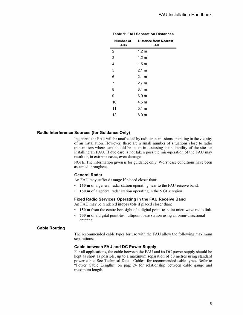
• Where two or three FAUs are to be mounted in the same area, they should be separated by at least 1.2 metres. When there are more than three FAUs in the same area, refer to Table 1 for recommended separation distances.
FAU Spacing and Clearance
FAU Installation Handbook
5
Radio Interference Sources (for Guidance Only)In general the FAU will be unaffected by radio transmissions operating in the vicinityof an installation. However, there are a small number of situations close to radiotransmitters where care should be taken in assessing the suitability of the site forinstalling an FAU. If due care is not taken possible mis-operation of the FAU mayresult or, in extreme cases, even damage. NOTE: The information given is for guidance only. Worst case conditions have beenassumed throughout.
General RadarAn FAU may suffer damage if placed closer than:• 250 m of a general radar station operating near to the FAU receive band.• 150 m of a general radar station operating in the 5 GHz region.
Fixed Radio Services Operating in the FAU Receive BandAn FAU may be rendered inoperable if placed closer than:• 150 m from the centre boresight of a digital point-to-point microwave radio link.• 700 m of a digital point-to-multipoint base station using an omni-directional
antenna.
Cable RoutingThe recommended cable types for use with the FAU allow the following maximumseparations:
Cable between FAU and DC Power Supply For all applications, the cable between the FAU and its DC power supply should bekept as short as possible, up to a maximum separation of 50 metres using standardpower cable. See Technical Data - Cables, for recommended cable types. Refer to“Power Cable Lengths” on page 24 for relationship between cable gauge andmaximum length.
Table 1: FAU Separation Distances
Number of FAUs
Distance from Nearest FAU
2 1.2 m3 1.2 m
4 1.5 m
5 2.1 m6 2.1 m
7 2.7 m
8 3.4 m9 3.9 m
10 4.5 m
11 5.1 m12 6.0 m

FAU Installation Handbook
6
FAU Block Diagram
Cable between FAU and Telecommunication Terminal ApparatusResidential applications <1.6 km (voice only).PABX applications <1.6 km (voice only).NOTE: This is the total length for all cabling to telephones including extensions.
FAU Applications
Lightning ProtectionConsideration MUST be given to protecting all external power andtelecommunication cabling against lightning especially where long lengths ofoverhead cable will be run from the FAU to terminal apparatus.Where lightning protection is considered necessary all protective devices should befitted in accordance with local regulations.
Switched DC Power Supply The unit must incorporate a disconnection device to allow the unit to be isolated from the primary power source.
1.6 km (1 mile)50 metres

FAU Installation Handbook
7
It is recommended that the DC power supply unit incorporates its own ON/OFFswitch to allow the FAU to be powered ON and OFF remotely.
Pole MountingThe FAU can be mounted on a standard pole, see Technical Data and Appendix.The following maximum stub pole free lengths are supported subject to the local in-country regulations.• 1.5 metres maximum for nominal 50 mm diameter stub pole.• 3 metres maximum for nominal 100 mm diameter stub pole.NOTE: Since the FAU should be mounted at least 2m above the roof level or highestobstruction (see “Planning the Location for the FAU” on page 4) the 50mm diameterstub pole should only be used as a “jockey pole”, i.e. fitted to a mast. See “TypicalWall and Pole Mounting of the FAU” on page 26 for an example.
Preparatory Field Engineering WorkThe following checklist details some of the main engineering field activities, whichmay need to have been completed before installing the FAU:• Erection of mast / pole. • Installation of the NID box and line-jack socket(s) at the subscribers
premises/PABX installation.• Cabling of AC mains supply to DC Power Supply Unit, if applicable.• Installation of DC Power Supply Unit and any stand-by power supply.• Installation of telephony cabling from FAU to building.• Installation of power supply cabling from FAU to DC power supply unit.• Provision of earthing system for FAU.
Preparation and Configuration of the FAU Preparation and configuration of the FAU at the installer’s depot is essential beforefield installation can take place.The following checklist details the pre-requisite activities to be carried out for eachFAU:• Unpack the FAU and check all packaged contents, refer to check list enclosed in
packaging.

FAU Installation Handbook
9
InstallationCheck the unit for transit damage and verify that the rear cover is secure. Cross checkthat the FAU identity number (IMEI number) on the base of the unit, is the oneallocated to the subscriber.
FAU Label
Assembling the FAUSun shields and antennas must be fitted to the FAU housing before fitting the unit toa pole.NOTE: Both front and rear sun shields must always be fitted.1. Place the front sun shield in position on housing ensuring it locates correctly
with screw holes.2. Position the rear sun shields and insert four screws through rear sun shield and
housing into front sun shield.3. Tighten screws in turn to 0.8-1.0 Nm torque. Do not overtighten these screws or
the sun shields could be damaged.
Fitting Sun Shields
4. Insert sealing ‘O’ rings into antenna sockets of main housing.5. Place both antennas in position; they are keyed to ensure correct location of each
antenna and mating of antenna connectors.6. Secure the antennas using the captive screws and tighten to 0.8-1.0 Nm torque.

FAU Installation Handbook
10
Fitting the Antenna
Fitting the FAUThe installer will first need to decide the appropriate method for installing the FAU,see Pre-Installation.
1. Where conditions allow, mount the FAU on a pre-installed stub pole or mast, by using the handle provided on the FAU. Typically, these situations will arise only where the top of the pole can be reached safely and easily. Connection of cables will then be possible after the FAU has been secured in position.
WARNING:DANGER TO PERSONNELDo not install the FAU during a lightning storm.
WARNING:HAZARDOUS VOLTAGESUse caution when installing or modifying telephone lines as hazardous voltages may be present.

FAU Installation Handbook
11
2. In situations where the top of the pole cannot be reached safely; FAU mounting may be better achieved by mounting the FAU to the stub pole, connecting all cables and then erecting and securing to the mast with the FAU in position.
The following procedure may need to be adapted to suit the chosen method ofinstallation:1. Prepare the FAU for mounting at the top of the pole by loosely fitting the two
pole-clamps on the back of the FAU. The screw length will depend on the diam-eter of the pole, e.g. a nominal 100 mm pole uses an 80 mm long screw, and a nominal 50 mm pole uses a 25 mm long screw.
2. Lift the FAU over the top of the pole passing the pole through both brackets until the top of the pole butts fully against the FAU handle/stop-plate, see below.
3. Secure the FAU to the pole by tightening the clamp bolts to 3±0.5 Nm torque.
FAU Pole Mounting
WARNING:DANGER TO PERSONNELThe FAU may fall down if it is incorrectly mounted on pole.
WARNING:DANGER TO PERSONNELEnsure the FAU is securely mounted before powering-up.

FAU Installation Handbook
12
FAU ConnectionsEach FAU has seven external Connections:• Antenna Rx.• Antenna Tx.• Bolt - Earthing cable.• Connector - 2-wire telephony cable.
• Connector - 2-wire DC power feed.• Connector - PDI cable for configuration and commissioning.
FAU Connections

FAU Installation Handbook
13
Telephone ( )The drawing below shows the pin connections of the socket.1. Unscrew the castellated locking ring on connector to remove the 2-pin insert.
(You can use the dust cover as a wrench to unscrew the locking ring.)2. Slacken the cable-clamping nut and insert the cable into the connector.3. Connect the appropriate wires to pins L and N of the 2-pin insert, and then
tighten the securing screws.4. Replace the insert and then tighten the castellated locking ring and cable clamp.5. Plug into the FAU and tighten the retaining ring.
Telephone Line Connections
The telephone cable should be supported at regular intervals along its route accordingto local regulations. Typically, a fixing every 300 mm or so is common. P-Clips orAll Weather Ty-wraps are generally used for this but whatever supports are chosenmust be suitable for the cable diameter and chosen to suit the surface or surfaces atthat particular site. Waterproof sealant should be used to seal and weather-proof thepoint of entry of the cable into the building following local installation standards.Ensure the installation is aesthetically pleasing.
Power ( )The drawing below shows the pin connections of the power socket. Refer to “PowerCable Lengths” on page 24 for the relationship between the cable gauge and themaximum length.1. Unscrew the castellated locking ring on connector to remove the 2-pin insert.
(You can use the dust cover as a wrench to unscrew the locking ring.)2. Slacken the the cable-clamping nut and insert the cable into the connector.3. Connect the appropriate wires to sockets L and N and tighten the securing
screws.
Table 2: Cable ConnectorsManufacturer: Bulgin Type: Buccaneer sealed
Connector No of ways required Bulk head Connector Cable Connector - Flex
Mounting (not supplied)
PDI 25-way Panel Plug - fitted with 25-way crimp pin insert.
Socket - fitted with25-way crimp pin insert.
Power 2-way Panel Plug - fitted with 2-way screw type terminal.
Socket - fitted with 2-way screw typeterminal.
Telephone Line (A & B lines)
2-way Panel Socket - fitted with 2-way screw type terminal.
Plug - fitted with 2-way screw type terminal.
Pin No. FunctionL A (Tip)N B (Ring)

FAU Installation Handbook
14
4. Replace the insert and then tighten the castellated locking ring and cable clamp.5. Plug into the FAU and tighten the retaining ring.The power source should provide +48 volts DC with respect to the FAU case. Thepower cable should be supported at regular intervals along its route according to localregulations. Waterproof sealant should be used to seal and weatherproof the point ofentry of the cable into the building following local installation standards.
Power Socket Connections
PDI ( )The PDI cable enters a socket at the base of the FAU. When the socket is not in use,ensure that the dust cap is securely fitted to protect the FAU from dust and moistureingress.NOTE: There is no supplementary surge protection on the PDI port in addition to thatnormally provided on an RS232 port.
SAFETY - Earth/Ground
The FAU enclosure must be connected to a single protective earth. A separate copperearth cable must be installed from the FAU to an earth / ground, in accordance withlocal regulations.
Earthing Connection
Ensure the earthing conductor is attached to the housing as shown above usingtoothed washer to provide good contact.
DANGER:EARTH LEAKAGE CURRENTSUnder no circumstances shall the FAU be operated without a protective copper earthing conductor.
EARTHING CABLEWITH RING TAG(NOT SUPPLIED)
M6 EARTHING BOLT
EXTERNALTOOTHEDWASHER

Install the junction box
15
Install th
e jun
ction
box
Note
Th
e outside screw
on th
e jun
ction box cover disables th
e locking
mechan
ism. If th
e jun
ction box is n
ot locked, you can
open the
junction box by pressin
g the tab located on
the opposite side an
d lift th
e cover.
Warn
ing
Ru
n in
door wiring from
the ju
nction box directly in
to the
structu
re in th
e shortest distan
ce practical. Wires from
the
junction box to th
e buildin
g interior sh
ould enter th
e buildin
g alm
ost imm
ediately after exiting th
e jun
ction box.
Warn
ing
Do n
ot run
RA
U or jun
ction box groun
d cables inside a bu
ilding.
Th
e jun
ction box is the in
terface between
the ou
tside cables and th
e inside cables. T
he ju
nction
box mu
st be located on th
e outside of th
e building im
mediately at th
e point wh
ere the
indoor cables reach
the ou
tside of the bu
ilding.
When
properly grounded, th
e junction
box min
imizes dam
age to the teleph
one an
d lowers th
e risk of inju
ry to the u
ser in th
e even
t the R
AU
or its cabling are stru
ck by lightnin
g in an
electrical storm
.
Th
e jun
ction box m
ay not adequ
ately protect the user if th
e R
AU
or its cabling are struck by ligh
tning w
hile th
e phon
e is in
use.
Warn
ing
Even
thou
gh th
e FS
Pin
cludes grou
ndin
g and circu
itryto
protect equipm
ent, facilities, an
d personn
el from n
earby ligh
tning, ligh
tnin
g is a high
ly un
predictable and dan
gerous ph
enom
enon
. It is impossible to com
pletely protect equipm
ent
and person
nel from ligh
tning.
Service p
rovider
accessclo
sed

Install the junction box
16
1.T
he ju
nction
box is the in
terface between
the ou
tside and th
e in
side cabling. T
he ju
nction
box mu
st be located on th
e outside of
the bu
ilding im
mediately at th
e point w
here th
e indoor cables
reach th
e outside of th
e buildin
g.
2.W
ith appropriate screw
s (not in
cluded), m
oun
t the ju
nction
box u
pright on th
e outside of th
e buildin
g so that th
e cables exit from
the bottom
of the jun
ction box. T
his position ensu
res that th
e jun
ction box componen
ts are not h
armed by w
eather, especially rain
. (See T
able 9 on page 20 for recom
men
ded materials for
moun
ting on
a wall.)
Note
CR
IMP
RIN
GS
. Use crim
p rings to con
nect w
ires to a term
inal or oth
er screw. C
rimp rin
gs are not
required, bu
t can be u
sed to keep the w
ires un
der controlw
hile
makin
g a good conn
ection.
–F
ive blue (16 to 14 A
WG
)
–F
our yellow
(26 to 24 AW
G)
–O
ne blu
e (6 AW
G)
To u
se crimp rin
gs:
–S
trip 1.27 cm (0.5 in
ch) of coverin
g from th
e wires.
–S
lide crimp rin
g over wire en
ds, ensu
ring you
cover the
bare wires. N
ote that th
e crimp rin
g can n
ot be removed
easily after crimpin
g.
–U
sing a crimpin
g tool, crimp the rin
g over the w
ires so it form
s a un
it with th
e wires.
–C
onnect th
e wires to screw
posts usin
g the rou
nded m
etal end. (S
ee Figu
re 20.)
Service
provid
er accesso
pen
Ring
+48 V
Earth groun d
Tip
Tip
(to bldg.)
Ring
(to bldg.)

Run indoor w
iring for the telephone and data
18
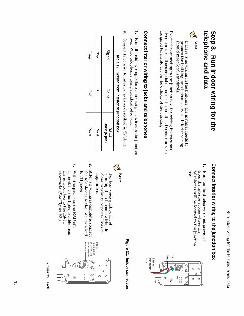
Step
8. Ru
n in
do
or w
iring
for th
e telep
ho
ne an
d d
ataN
ote
If there is n
o wirin
g in th
e buildin
g, the in
staller needs to
prepare the building for teleph
one service. In
terior wirin
g sh
ould m
eet local standards.
Except for con
nectin
g to the jun
ction box, the w
iring in
struction
s given
here are all accom
plished in
side the bu
ilding. D
o not run w
ires design
edfor in
sideu
seon
the
outside of
the
buildin
g.
Co
nn
ect interio
r wirin
g to
jacks and
teleph
on
es
1.R
un
all inside w
iring before con
nectin
g the w
ires to the ju
nction
box. W
ire telephon
es usin
g standard telco w
ire.
2.C
onnect telco w
ire to interior jacks as described in
Table 12.
Co
nn
ect interio
r wirin
g to
the ju
nctio
n b
ox
1.R
un
standard telco w
ire (not provided)
from th
e interior room
s wh
ere the
telephon
es will be located to th
e jun
ction
box.
Fig
ure 22. In
do
or co
nn
ection
Note
For best voice qu
ality, avoid ru
nn
ing th
e telephon
e wirin
g in
close proximity to pow
er lines or
appliances.
2.A
fter all wirin
g is complete, con
nect
the teleph
ones to th
e interior w
ired R
J-11 jacks.
3.W
ith th
e power to th
e RA
U off,
connect th
e short ph
one cable inside
the ju
nction box to th
e RJ-11
receptacle. (See F
igure 23.)
Fig
ure 23. Jack
Table 12. W
iring
from
interio
r to ju
nctio
n b
ox
Sig
nal
Co
lor
RJ-11
Jack (6 pin
)
Tip
Green
Pin
4
Rin
gR
edP
in 3
Ring
TipInterior
telephonew
ire
RJ-II jack.
To test, unplug pigtail and plug in a know
n good telephone

FAU Installation Handbook
19
CommissioningThe following instructions enable the installation engineer to ensure the system isworking correctly before leaving the installation.After checking that the installation is complete, correct and that all earth connectionsare good the system must be tested.
Power-Up
Switch on the DC power supply to power up the FAU and wait one minute for systemregistration.If the ambient temperature is between -15oC and -30oC allow the unit approximately10 minutes to warm up and switch on. The actual time taken depends upon thetemperature and the exact voltage to the FAU; the higher the voltage, the lower thetime required. (10 minutes is the expected warm-up time at -30oC with a nominalvoltage of 48V.) If you attempt to make a test call before the unit has warmed up, notone will be heard.
Making a test call• Lift the telephone handset.• The Dial Tone should be heard. If you hear the ACB tone, replace the handset
and retry after 1 minute. If you still get the ACB tone after 3 attempts, switch off the FAU and repeat the power-up sequence. If the ACB tone persists, see “Fault Finding” on page 21, and follow the instructions in the flowchart.
• Dial the test call telephone number and finish with the ‘#’ key. If the Equipment Engaged (Busy) tone is heard, replace the handset and try again later.
• When the call is answered, talk for a short period to ensure you can hear and be heard. Press down a button on the telephone keypad. Ensure that the called party hears a clear tone. Ask them to press a button so you can check for a clear tone as well.
• Arrange for the called party to dial the FAU to test incoming calls.• Hang-up to terminate the call.
Receiving an Incoming Test CallWhen the telephone rings, wait for about 3 seconds before picking up the phone. Thisconfirms the ringing circuits of the FAU are OK. Talk for a short period, ensure thatyou can hear, and can be heard, then hang-up.
DANGER: HAZARDOUS VOLTAGESHazardous voltages will be present within the FAU once power has been applied.
DANGER:HAZARDOUS VOLTAGESAvoid electrical contact with the telephone wires, hazardous voltages may be present.

FAU Installation Handbook
20
Reset Functions
Auto ResetThe FAU will reset itself after there are 6 consecutive call attempts without satellitecontact in a 15 minute period.
Hook FlashThe FAU reset itself after 6 consecutive breaks are made on the hook switch of thetelephone in a 15 minute period.NOTE:Once an Auto Reset or Hook Flash Reset has occured, both features are thenunavailable for a period of 15 minutes. This is necessary to avoid accidentaloperation of the reset and to give the FAU suffficient time to re-register in extremesituations.
Power ResetTurning the power to the FAU off and on again will cause a reset.A power reset may be completed at any time.

FAU Installation Handbook
21
Fault FindingThe following chart will help in finding simple faults when making a test call. Anyother faults should be reported to the service provider and the unit returned forinternal checking.

Fault Finding Chart

FAU Installation Handbook
22
Technical Data - FAU
FAU Outline Drawing

FAU Installation Handbook
23
PhysicalColour Light grey.Dimensions
Including antennas W 300 x D 175 x H 525 mm.Excluding antennas W 300 x D 175 x H 300 mm.
Weight 7.3 kg.Degree of ingress protection EN 60529 IP55.
Power requirementsSupply voltage +48 V DC nominal, +44 to +54 V DC.Supply ripple 200 mVrms maximum.Input current 1.0 A maximum.Power consumption 50 W maximum.
EnvironmentalStorage temperature -30 to +70° C.Transportation temperature -30 to +70° C.Operating temperature -30 to +60° C with 1120W/m2 solar radiation.Relative humidity Up to 90%.Altitude Sea level to 5000 m.
InterfacesTelephone port Analogue subscriber line.
UK standard, 600 ohms (resistive).(other country standards are available).
DTMF ITU-T Q.23.Supports terminal equipment up to REN=3.Loop calling unguarded clearing.Line reversal.Clear backward.
Data port Not currently supported.
PDI port Connector for configuration and commissioning toolRS232 levels.
Air interface Standards Globalstar Air Interface (GAI).Transmit frequency 1610.0 to 1626.5MHz.Receive frequency 2483.5 to 2500.0MHz.Transmit power +37dBm EIRP maximum.Receiver G/T ratio -24.4 dB/K minimum -80 to +80 degrees.
-23.5 dB/K minimum -75 to +75 degrees.

FAU Installation Handbook
24
InstallationOn stub pole With mounting kit supplied for pole diameters
47.8 - 48.8 mm or 100.6 - 102.6 mm.Cable connectors Bulgin ‘Buccaneer’ Flexmount range (not supplied).
Power Socket - 2-way screw type terminal.Telephone Plug - 2-way screw type terminal.PDI Socket - 25-way crimp or solder socket.
For more details on cable connectors, see “Bulgin Buccaneer Flexmount Connectors - Summary” on page 24.
StandardsSafety
European Union EN 60215, EN 60950.EMC
European Union EN 300 733, EN 300 831.US FCC CFR 47 Part 15B.
Environmental ETS 300 019 Classes 1.2, 2.3 and 4.1 with exceptions.
Technical Data - CablesNOTE: All cables should meet local regulations in the country of installation. Thissection gives recommended values.
Cable between FAU and PSUNumber of wires 2 conductor.Length 50 M, 165' maximum.Wire type Solid or stranded.Wire diameter 20 AWG or equivalent for up to 50 metres length.Outer cable diameter 6.0 mm minimum, 8.1 mm maximum.Insulation material PVC or PE.
FAU Installation Handbook
25
Insulation between wires must withstand 750 Vrms during 1 minute.Temperature -40 to +80° C (where local conditions allow a lower
specification cable may be selected).Working voltage 100 Vrms.
Cable between FAU and cross-connectNumber of wires 2 core twisted pair.Length 1609 M, 5280' maximum.
(total length of all cabling to telephones includingextensions).
Wire type Solid or stranded.Wire diameter 0.4 mm minimum (26 AWG).Outer cable diameter 5.5 mm nominal.Insulation material PVC or PE.Insulation between wires Must withstand 750 Vrms during 1 minute.Temperature -40 to +80° C (where local conditions allow a lower
specification cable may be selected).Working voltage 100 Vrms.
CAUTION: To reduce the risk of fire use only 26 AWG or larger telecommunication line cord.
Protective Earth Cable (typical)Wire type Stranded.Wire diameter 12 AWG Copper.Colour Green or yellow.
Additional Information
RF (Radio Frequency) SafetyThe FAU200 SAT has been tested in accordance with RF safety guidelines on humanexposure to RF fields. When installed using the procedures described in thisHandbook the FAU200 SAT produces RF exposures well below international safetylimits and conforms to the recommendations of the ICNIRP (InternationalCommission on Non-Ionising Radiation Protection) and to international exposurestandards, such as:• CENELEC European Pre-standard ENV50166-2.• US standard ANSI/IEEE C95.1-1992.Maintenance work on the FAU200 SAT antenna during operation will not generateRF exposure levels exceeding the safety limits.

FAU Installation Handbook
26
PatentsThis product is manufactured under licence to one or more of the patents of Qualcomm Incorporated, other patents pending.
Limitations of UseThis product cannot be used for data messaging and position determination servicesover the Globalstar system servicing fleets of motor vehicles, rail cars and/or vesselsin the transportation industry, private fleets (i.e. fleets of motor vehicles, rail carsand/or vessels which a person or entity utilises to provide repair, installation orservice to its customers) and any systems which provide data communications,monitoring and control between a remote fixed site and a central point.
Table 3: Patents
4,901,307 5,416,797 5,566,357 5,627,8575,056,109 5,426,392 5,568,483 5,629,955
5,099,204 5,442,627 5,572,172 5,629,975
5,101,501 5,452,473 5,574,773 5,633,8815,103,459 5,461,639 5,576,662 5,638,412
5,107,225 5,469,115 5,577,022 5,640,414
5,109,390 5,475,870 5,577,025 5,642,3985,228,054 5,479,475 5,581,575 5,644,591
5,257,283 5,485,486 5,588,043 5,644,596
5,265,119 5,487,175 5,590,069 5,646,9915,267,261 5,490,165 5,590,406 5,652,599
5,267,262 5,497,395 5,590,408 5,654,979
5,283,536 5,499,280 5,592,481 5,655,2205,289,527 5,504,773 5,592,548 5,657,420
5,307,405 5,506,865 5,594,718 5,666,122
5,309,474 5,509,015 5,596,570 5,673,2595,339,046 5,511,067 5,600,754 5,675,644
5,341,456 5,511,073 5,602,833 5,687,229
5,373,259 5,528,593 5,603,096 5,689,5575,383,219 5,544,196 5,604,730 5,691,974
5,392,287 5,546,459 5,617,060 5,692,006
5,396,516 5,561,618 5,621,7845,408,697 5,566,000 5,621,853
5,414,796 5,566,206 5,625,876
FAU Installation Handbook
27
APPENDIXAdditional Cable Information and Typical Installation Details
This appendix gives the following information:• Additional specifications for cables and connectors, including part numbers and
pin-outs where appropriate.• Some drawings showing typical wall and pole mounting of the FAU using a stub
pole.The diagrams given in this appendix are listed below:• Bulgin Buccaneer Flexmount Connectors - Summary.• Power Cable Lengths.
• Typical Wall Mounting of FAU on Stub Pole.• Typical Pole Mounting of FAU using a Jockey Pole.• Typical Jockey Pole Mounting: Detail.

FAU Installation Handbook
28
Additional Specifications for Cables and Connectors
Bulgin Buccaneer Flexmount Connectors - Summary
When buying from Bulgin, connectors may be bought with different glands to acceptcables of various outside diameters. The glands may also be purchased separately.
Part Numbers correct at time of printing.Please note that minimum order quantities may apply to Bulgin connectors andaccessories, particularly to QX part numbers.
Power Cable LengthsThe table below details the relationship between cable gauge and maximum possiblelength in metres. The table has been prepared using the following assumptions.• The minimum voltage at the FAU terminals is 44V.• The power source has a 48V output or greater.• The maximum permissible voltage drop is 4V at a maximum current of 0.8A.• The maximum loop resistance of the power cable is 5Ω.• A 20% tolerance allowed for variation in temperature.
This table shows the acceptable cable lengths (*) against wire gauge at 25°C.
Cable Connector Type Bulgin-20°C to +70 °COperation
-45°C to +70°COperation
Power Connector 2-way socket PX0736/S QX3164Telephone Connector 2-way plug PX0736/P QX3163
Cable Acceptance Bulgin Part NumberBulgin Part Number Cable Outside Diameter To Order Glands Separately
As fitted, for 2-way connectors ∅ 6 - 8mm 12023 (Black)/04 ∅ 3.5 - 5mm 12023/5 (Grey)/05 ∅ 5 - 7mm 12023/1 (White)/07 (as fitted for 25-way connector)
∅ 7 - 9mm 12023/2 (Yellow)
For example, to order an FAU Power Connector fitted with a White ∅5-7mm gland, order part PX0736/S/05 (for -20°C operation ) or QX3164/05 (for -45°C operation)
AWGCopper
Resistivity Maximum Cable Length in Metres
Ωm-1 5 10 15 20 25 30 35 40 45 50
18 0.0209 20 0.0333 22 0.0530 24 0.0842 26 0.1339 28 0.2129

FAU Installation Handbook
29
Typical Wall and Pole Mounting of the FAU
Typical Wall Mounting of FAU on Stub PoleTo assist in the installation of the FAU200 SAT in various locations, the followingpages give typical installation details. These include mounting on the end wall of abuilding or on top of a pole. In all cases ensure the FAU has a clear view of the sky.

FAU Installation Handbook
30
Typical Pole Mounting of FAU using a Jockey Pole

FAU Installation Handbook
31
Typical Jockey Pole Mounting: Detail

FAU Installation Handbook
32

FAU Installation Handbook
33
FAU200 SAT Installation Handbook
![Relaunch IdM-Portal der FAU mit dem neuen FAU-Adressbuch · 2016. 10. 27. · REGIONALES RECHENZENTRUM ERLANGEN [RRZE] Relaunch IdM-Portal der FAU mit dem neuen FAU-Adressbuch RRZE-Campustreffen,](https://img.dokumen.tips/doc/110x75/611e4e26525d6d085d3d554f/relaunch-idm-portal-der-fau-mit-dem-neuen-fau-adressbuch-2016-10-27-regionales.jpg)