Embed Size (px)
Citation preview
FIV for Subsea Production Systems
Part 1: challenges and case example
Arnaud Sanchis, Specialist Flow Assurance Engineer

What is a Subsea Production System (SPS)?
2
Shell Perdido SPS, Brazil, 2900 m water depth
Production trees Production
jumper
Production
manifold
Towards production
platform Separation and
boosting system
MEK 4450 Offshore Technology
Why are we concerned about vibrations from the flow?
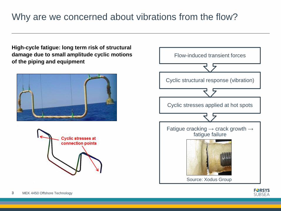
High-cycle fatigue: long term risk of structural
damage due to small amplitude cyclic motions
of the piping and equipment
3
Fatigue cracking → crack growth → fatigue failure
Cyclic stresses applied at hot spots
Cyclic structural response (vibration)
Flow-induced transient forces
Source: Xodus Group
3 MEK 4450 Offshore Technology
Types of flow-induced transient forces
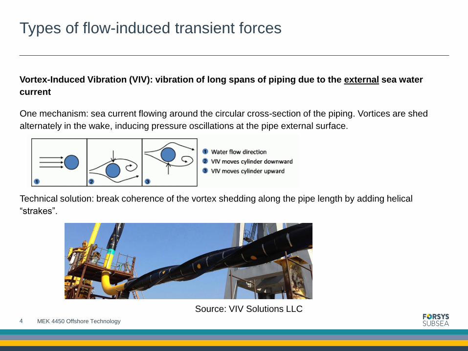
Vortex-Induced Vibration (VIV): vibration of long spans of piping due to the external sea water
current
One mechanism: sea current flowing around the circular cross-section of the piping. Vortices are shed
alternately in the wake, inducing pressure oscillations at the pipe external surface.
Technical solution: break coherence of the vortex shedding along the pipe length by adding helical
“strakes”.
4
Source: VIV Solutions LLC
MEK 4450 Offshore Technology

Types of flow-induced transient forces
Flow-Induced Vibration (FIV): vibration of piping and equipment due to the internal flow of
hydrocarbons, chemicals, water, etc…
Multiple mechanisms
• Acoustic pulsations in gas filled systems
• Multiphase flow excitation at bends in the piping
• Fast closing valves in liquid system
• Vortex shedding around intrusive elements
• Etc…
Example: flow-induced pulsations through corrugated piping
• Known as “singing riser” issue
• Cause: flow-induced pressure perturbations
• due to the cavities in the piping walls
5
Source: TNO
MEK 4450 Offshore Technology

Types of flow-induced transient forces
Example: flow past a closed side branch (“dead leg”)
Vortices are formed at the upstream edge of the side branch opening, with a frequency 𝐹𝑓𝑙𝑢𝑖𝑑 = 𝑆𝑟∙𝑈𝑜
𝐷
where D is the side branch diameter and Sr is the Strouhal number.
The vortex formation and impingement on the downstream edge creates an oscillating pressure field in the
closed branch.
If the frequency of the perturbation matches one of the acoustic
modes, acoustic resonance will produce high pressure
pulsations inside the closed branch.
Acoustic natural frequencies: 𝐹𝑛 = 𝑐2𝑛−1
4𝐿
where c is the speed of sound and L is the length of the side branch.
6
Source: TNO
MEK 4450 Offshore Technology

Types of flow-induced transient forces
Example: multiphase excitation of pipe bends
7 MEK 4450 Offshore Technology
Source: FMC Technologies

Theory of mechanical vibration
Definition of vibration
Mechanical oscillation about an equilibrium position, i.e. repeating variation of a certain measure about a
central value or state.
Vibrations are caused by dynamic forces: structural dynamic problem
Differences with a structural static problem are
• The time-varying nature of the excitation
• The inertial forces in the system affect the response.
8
Beam loaded by a static
force
Beam loaded by a dynamic
force
MEK 4450 Offshore Technology

Structural modes of vibration
A structural system will vibrate according to its eigenmodes
• An eigenmode is a pattern of motion in which all parts of the system move sinusoidal with the same frequency and with
fixed phase shift. The corresponding frequencies of eigenmodes are called eigenfrequencies or natural frequencies.
A mode is the combination of
• A deflection shape
• A frequency of vibration.
Example: cantilever beam modes 1 and 2
9
Excitation at 19 Hz Excitation at 120 Hz
Source: Tech Damper AS
MEK 4450 Offshore Technology

Forms of vibration
Periodic vibration
The amplitude is repeated after a discrete time
period
The amplitude can be decomposed as a series of
sine waves
Harmonic vibration
The amplitude corresponds to a single sine wave
Can only occur is the excitation force is at a single
frequency
Non periodic
10 MEK 4450 Offshore Technology
Single degree of freedom system
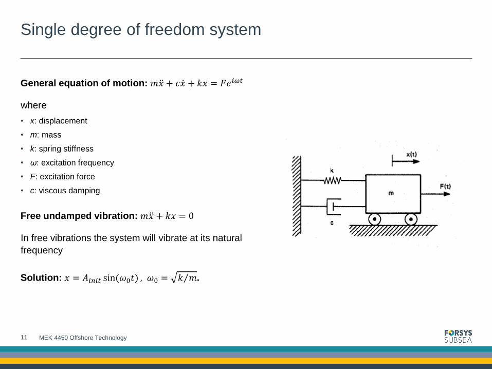
General equation of motion: 𝑚𝑥 + 𝑐𝑥 + 𝑘𝑥 = 𝐹𝑒𝑖𝜔𝑡
where
• x: displacement
• m: mass
• k: spring stiffness
• ω: excitation frequency
• F: excitation force
• c: viscous damping
Free undamped vibration: 𝑚𝑥 + 𝑘𝑥 = 0
In free vibrations the system will vibrate at its natural
frequency
Solution: 𝑥 = 𝐴𝑖𝑛𝑖𝑡 sin(𝜔0𝑡) , 𝜔0 = 𝑘 𝑚 .
11 MEK 4450 Offshore Technology
Single degree of freedom system
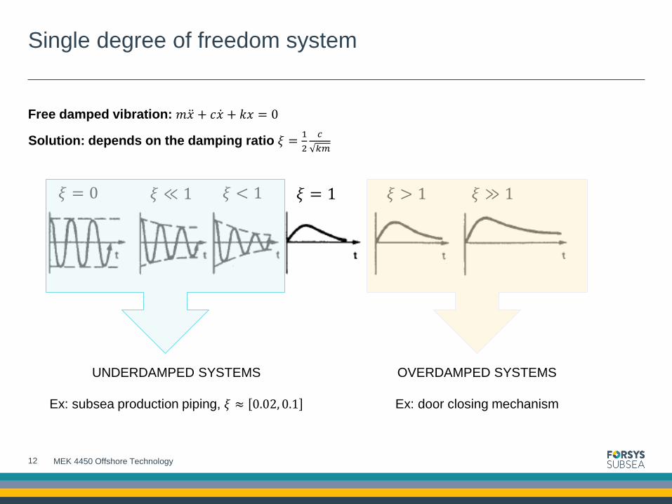
Free damped vibration: 𝑚𝑥 + 𝑐𝑥 + 𝑘𝑥 = 0
Solution: depends on the damping ratio 𝜉 =1
2
𝑐
𝑘𝑚
12
𝜉 = 0 𝜉 ≪ 1 𝜉 < 1 𝜉 = 1 𝜉 > 1 𝜉 ≫ 1
OVERDAMPED SYSTEMS
Ex: door closing mechanism
UNDERDAMPED SYSTEMS
Ex: subsea production piping, 𝜉 ≈ 0.02, 0.1
MEK 4450 Offshore Technology
Single degree of freedom system
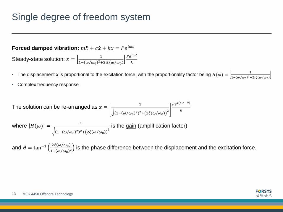
Forced damped vibration: 𝑚𝑥 + 𝑐𝑥 + 𝑘𝑥 = 𝐹𝑒𝑖𝜔𝑡
Steady-state solution: 𝑥 =1
1− 𝜔 𝜔0 2+2𝑖𝜉 𝜔 𝜔0
𝐹𝑒𝑖𝜔𝑡
𝑘
• The displacement x is proportional to the excitation force, with the proportionality factor being 𝐻(𝜔) =1
1− 𝜔 𝜔0 2+2𝑖𝜉 𝜔 𝜔0
• Complex frequency response
The solution can be re-arranged as 𝑥 =1
1− 𝜔 𝜔0 2 2+ 2𝜉 𝜔 𝜔0 2
𝐹𝑒𝑖 𝜔𝑡−𝜃
𝑘
where 𝐻(𝜔) =
1
1− 𝜔 𝜔0 2 2+ 2𝜉 𝜔 𝜔0 2 is the gain (amplification factor)
and 𝜃 = tan−12𝜉 𝜔 𝜔0
1− 𝜔 𝜔0 2 is the phase difference between the displacement and the excitation force.
13 MEK 4450 Offshore Technology

Single degree of freedom system
Forced damped vibration amplitude response characteristics
Peak response occurs at frequency 𝜔 = 𝜔0 1 − 2𝜉2
Peak value of the gain is 𝐻(𝜔) =1
2𝜉 1−𝜉2
14
𝜔 𝜔0
𝐻(𝜔)
𝜔 𝜔0
𝜃
MEK 4450 Offshore Technology
Resonance
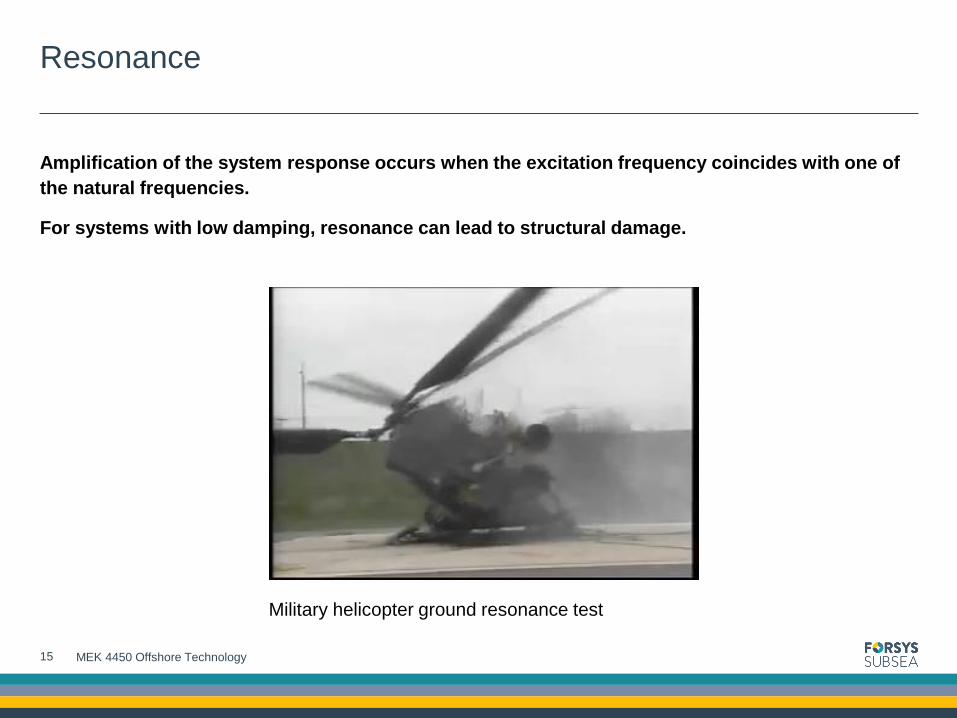
Amplification of the system response occurs when the excitation frequency coincides with one of
the natural frequencies.
For systems with low damping, resonance can lead to structural damage.
15
Military helicopter ground resonance test
MEK 4450 Offshore Technology

How to limit mechanical response to vibrations?
First assessment
Increase stiffness k (lower amplitude response over all frequencies)
• Ex: add supports to the piping.
Reduce/suppress excitation force F
• Ex: strakes for VIV.
Avoid resonance
Structural eigenfrequencies must be outside ± 20% of excitation frequencies
Achieved by tuning m, k or (if possible) the excitation force frequency ω
• Ex: increase diameter at the mouth of a closed branch.
If resonance cannot be avoided
Increase damping c to lower amplitude response
• Ex: damper solution applied to the structure.
16 MEK 4450 Offshore Technology

Case example: subsea production jumper
Function: carry production fluid (oil and gas)
from the production tree
Requirements:
• Flexibility
• Length
• Durability.
Sources of vibrations:
• Vortex-Induced Vibrations from the external sea current
• Flow-Induced Vibrations from the internal flow of oil and
gas.
17
Production
tree
Sea current
Oil and gas
MEK 4450 Offshore Technology

Vortex Induced Vibrations (VIV) mechanism
System: cylindrical body (the pipe) with perpendicular current
Vortices are formed downstream of the pipe cross-section with a frequency 𝐹𝑓𝑙𝑢𝑖𝑑 = 𝑆𝑟∙𝑈𝑜
𝐷 where D is the
pipe outer diameter and Sr is the Strouhal number. For a circular cross-section, Sr ≈ 0.2
Assumption: 2D system, no damping. 𝐹𝑚𝑒𝑐ℎ=1
2𝜋
𝑘
𝑚+𝑚𝑎, where ma is the added mass due to the water
around the body.
For a circular cylinder, ma = displaced mass of water
=𝜋𝜌𝑤𝑎𝑡𝑒𝑟𝐷
2𝐿
4
18 MEK 4450 Offshore Technology
Application (exercise 1)
The jumper is modeled as a 40 m long straight pipe fixed at both ends and filled with oil. The
seawater current is perpendicular to the jumper and has a velocity of 30 cm/s.
In order the avoid any risk of VIV, the vortex shedding frequency must be outside ± 20% of any
structure natural frequency.
Is there a risk of VIV for the jumper?
Input data:
• Pipe material: structural steel (A36 grade)
• Pipe outer diameter: 168.3 mm
• Pipe inner diameter: 124.4 mm
• Oil density: 800 kg/m3
• Water density: 1014 kg/m3
19 MEK 4450 Offshore Technology

Application (exercise 1)
Determination of jumper natural frequency
First mode natural frequency is given by 𝑓1 =𝜇1
2𝜋𝐿2𝐸𝐼
𝑤
• μ1 = frequency factor for mode 1
• L = pipe length between the supports [m]
• w = jumper mass (including oil and added mass of seawater) per unit length [kg/m]
• E = pipe material modulus of elasticity [N/m2]
• I = moment of inertia [m4].
20
𝐼 =𝜋
64𝐷𝑜𝑢𝑡𝑒𝑟4 − 𝐷𝑖𝑛𝑛𝑒𝑟
4
MEK 4450 Offshore Technology

Flow Induced Vibration (FIV) mechanism
Flow reaction force on a pipe bend for steady-state, single phase flow
Conservation of momentum applied on a control volume inside the bend
𝐹 =
𝑑
𝑑𝑡𝑚𝑣 =
𝜕
𝜕𝑡 𝜌𝑣 𝑑𝑉
𝑉
+ 𝜌𝑣 𝑆
𝑣 ∙ 𝑛 𝑑𝑆
Conventions:
• Normal vector is defined as positive outwards
• Pressure forces are defined as positive inward
Friction and gravity forces neglected
• Only forces considered are the reaction force from the bend element and the pressure force
• 𝐹 = 𝐹 𝑃 + 𝐹 𝑏→𝑓 , 𝐹𝑏→𝑓= Force applied by the bend element on the control volume
• Pressure force: 𝐹 𝑃 = −𝑃𝑛𝑆
𝑑𝑆
21
0 for steady-state flow
𝑛 𝑛
𝑛
P
P
𝑣
β
y
x
MEK 4450 Offshore Technology

Flow Induced Vibration (FIV) mechanism
Characteristics of multiphase flow
• Transient distribution of the phases
• Superficial phase velocities: 𝑈𝑖,𝑗𝑠 =
𝑄𝑖,𝑗
𝐴 where Qi is the volumetric flow rate of phase i
• Mixture velocity: 𝑈𝑚 = 𝑈𝑖𝑠 + 𝑈𝑗
𝑠
Flow regimes for horizontal flow
22 MEK 4450 Offshore Technology
A: pipe cross-sectional area
𝑈𝑔𝑆
𝑈𝑙𝑆

Flow Induced Vibration (FIV) mechanism
Simplified slug flow force calculation
Assumptions
• No gas entrainment in the liquid slug
• 𝜌𝑙 ≫ 𝜌𝑔
• Steep liquid front and tail
• No liquid film in the gas bubble
• 𝑈𝑠𝑙𝑢𝑔~1.2𝑈𝑚
Example for a 90° bend:
23 MEK 4450 Offshore Technology
𝐹 =𝜕
𝜕𝑡𝑚𝑣
𝐹𝑥 = 𝜌𝑙𝐴𝐿𝑠𝑙𝑢𝑔𝑈𝑠𝑙𝑢𝑔 − 0
Δ𝑡𝑝𝑎𝑠𝑠𝑎𝑔𝑒
𝐹𝑦 = 𝜌𝑙𝐴𝐿𝑠𝑙𝑢𝑔0 − −𝑈𝑠𝑙𝑢𝑔
Δ𝑡𝑝𝑎𝑠𝑠𝑎𝑔𝑒
Δ𝑡𝑝𝑎𝑠𝑠𝑎𝑔𝑒~𝐿𝑠𝑙𝑢𝑔
𝑈𝑠𝑙𝑢𝑔 (valid if Lslug >> length of the bend)
Fx
Fy
Lslug
Uslug
𝐹 = 𝐹𝑥2 + 𝐹𝑦
2 = 2𝜌𝑙𝐴𝑈𝑠𝑙𝑢𝑔2

Application (exercise 2)
Calculate the force due to the flow of water in a 45° bend. Friction and hydrostatic forces in the
bend are neglected. Operational pressure is expressed as relative to the external pressure.
Input data
• Operational pressure: 150 bar (relative to external pressure)
• Water density: 1010 kg/m3
• Volume flow rate: 50 000 barrels/day
• Pipe inner diameter: 139.8 mm.
Calculate the force due to an oil slug in a U-bend
Input data
• Gas superficial velocity: 5 m/s
• Oil superficial velocity: 2.8 m/s
• Oil density: 650 kg/m3
• Pipe inner diameter: 10 inches.
24 MEK 4450 Offshore Technology