Embed Size (px)
Citation preview

610003 CLIENT:
DOC. Nr. Doc. Rev. n. 0
JOB TITLE
REPORT
TITLE
CERN
Rev. Date Prep. Check. App.
0 14/11/2018 AB AB AB
2.1
2.2
2.3
2.4
2.5
2.6
2.7
2.8
2.9
2.10
API RECOMMENDED PRACTICE 688 “Pulsation and Vibration Control in Positive Displacement Machinery,
Systems for Petroleum, Petrochemical, and Natural Gas In-dustry Services”, 1st Ed., April 2012.
Hemon P., Santi F., Amandolèse X.: "On the pressure oscillations inside a deep cavity excited by a grazing
airflow" European Journal of Mechanics B/Fluids 23 (2004) 617-632
Amandolèse X., Hemon P., Santi F.: "An experimental study of the acoustic oscillations by flow over cavities"
Transactions of the ASME Vol. 126, pp 190-195, April 2004
2 REFERENCE DOCUMENTS
CERN
610003-REP-WP4-T001
FIV ANALYSIS
SUMMARY
n-Tof Target #3 - Preliminary Flow Induced Vibration analysis - detailed calculations
CERN n-Tof - ANALYSIS OF FLOW INDUCED VIBRATIONS
Distribution:
Document history
ISO 10816-1 Mechanical vibration - Evaluation of machine viration by measurement on non-rotating parts -
part 1 General guidelines
First issue for approval
Junkowski W.M., Botros K.K., Studzinski W.: " Cyindrical side-branch as tone generator" Journal of Sound
and Vibration (1989) 131(2), 265-285
NIST Standard Reference Database 23: https://www.nist.gov/publications/nist-standard-reference-database-
23-nist-thermodynamic-and-transport-properties-refprop
1 SCOPE
This document describes the results obtained by a spreadsheet calculation to preliminarily check if FIV can arise due to
lock-on among vortex excited at side opening of cavities facing a fluid flow through the main tube of the n-Tof Target cradle.
In the present case the main duct is one of the nitrogen lines feeding the cooling flow at the bottom of the anticreep plates
cradle, while the side cavity consists of each of the five volumes trapped between two anticreep plates of the Target block
(see Figures 1 and 2).
Energy Institute, “Guidelines for the Avoidance of Vibration Induced Fatigue Failure in Process Pipework”, 2nd
edition January 2008, Energy Institute, London.
CERN Rui Ximenes EN-STI "n-Tof Target #3 - Vibration analysis meeting with SATE" (12/09/2018)
CERN Rui Ximenes EN-STI "n-Tof Target #3 - Flow Induced Vibration support documentation from CERN"
(16/10/2018)
Ziada S., Shine S.: "Strouhal numbers of flow-excited acoustic resonance of closed side branches", Journal of
Fluids and Structures (1999) 13, 127-142
File: nTOF_Target#3_FIV_basis_00ab181114.xlsxSheet: Cover
Printed: 14/11/2018, 20:08

FIV ANALYSIS
SUMMARY
4 VORTEX SOURCES
The potential vortexes sources considered are the circular arcs (≈ 142 mm long) through which the gas passes from the
bottom ducts into the channels between the anti-creep plates. These openings have a small dimension (10 mm) along the
fluid direction. This is the one to be considered in the calculation of the Strouhal number and compare it with literature data
on closed or flowing side branches.
The main flow velocity in front of the openings is calculated for each one considering 50% of the total flow rate entering
each of the two ducts and decreased by 1/5 after the passing in front of each of the anti-creep plate ports.
The reduction of the local velocity in front of the ports, due to the 90° bend upstream the ducts inlet is neglected,
considering that a wide range of Strouhal number values, bewteen 0.2 and 0.5, is considered for the acoustic lock-on
checks. This assumption is anyway conservative as the vortex sources are on the innerside of the bend, thus in a lower
velocity zone.
b) Channel tube oscillators
Two additional oscillation modes are considered as an approximation of the more complex acoustic modes extending
between the former Helmoltz neck port and the top discharge side from the cooling channels.
The parallel channels of rectangular cross section of 20 x 3 mm (Figure 4) are considered as stand alone tubes having
reflective open end boundaries.
The first two corresponding modes considered are therefore:
one with the channel length equal to half a wavelength (two pressure nodes, at the bottom and top ends) and
one with the channel length equal to one wave length (three pressure nodes, the former plus one at the mid point of the
channel).
The length of the channel (550 mm) is taken as the average of the 21 pairs, which differ in length since their lower ends are
enveloped by a circular arc (Figure 2 right). This assumption yields a conservative evaluation of the resonant pattern as the
differing lengths of the parallel tubes would cause a smoother modal response due to the partly distructive interference
among the respective standing waves. Should a more detailed analysis be necessary an acoustic model with parallel tubes
of different length should be considered to verify this hypothesis.
3 GAS PROPERTIES
The gas (nitrogen) properties are calculated by means of the REFPROP (Ref. 2.10) tool, considering a total absolute
pressure at the inlet of the cradle of 1.013 bar a and a temperature of 20 °C as a base case.
Density and other properties are calculated neglecting the effects of the pressure losses across the channels.
A sensitivity analysis has been performed at ±10% pressure.
5 RESONANT ACOUSTIC SYSTEMS
The acoustic systems considered to potentially resonate are the following
a) Helmoltz type oscillator
This is composed of the volume trapped between two anti-creep plates (Figures 2 and 3), i.e. all the 21 x 2 gaps like those
shown in cross section in Figure 4, considering an average length of the channels of 550 mm, and a cross section of each
channel of 3 x 20 mm (thickness x gap left between ribs). The total volume of this cavity sums up to ≈1700 cm3, including
the distribution zone on the lower part (Figure 5).
The Helmoltz cavity volume communicates by a potentially oscillating flow through a neck port having a width of 10 mm, a
developed breadth of 142 mm along an arc of about 270° and a thickness of 3.5 mm (estimated). An added thickness of
13.2 mm is accounted for, to consider the actual oscillating fluid stream inertia, according to Hémon, Santi, Amandolèse
(2003, Ref. 2.7).
File: nTOF_Target#3_FIV_basis_00ab181114.xlsxSheet: Cover
Printed: 14/11/2018, 20:08

FIV ANALYSIS
SUMMARY
7 CONCLUSIONS
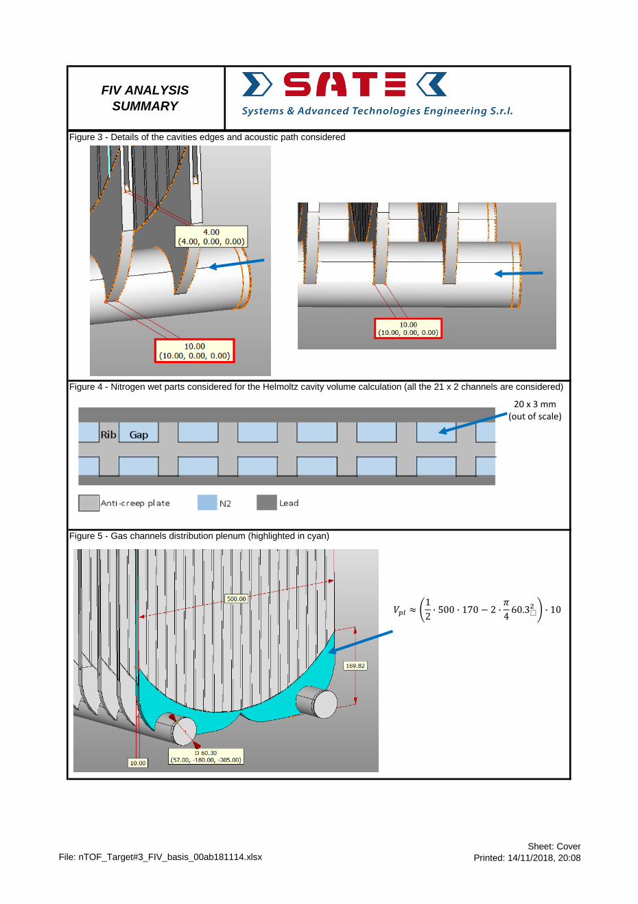
The potential vortex frequency at the cradle ports openings span a range from about 130 Hz to about 2 kHz, depending on
the operating condition (A or B) and on the port, out of the five channels rows at the base case pressure (1 atm).
However only in some of them the Reynolds number exceeds the minimum value (1e5) needed to power self-excited
standing waves by lock on of acoustic modes, when theoretical frequencies match.
Moreover above a certain grazing speed none of the three base acoustic modes considered (Helmoltz cavity, 1st and 2nd
channels modes) would be locked to the vortex frequencies.
This restricts the potential acoustic-vortex lock-on frequencies to the range between about 500 Hz and 1.6 kHz in the base
case pressure.
Only the acoustic resonance of the one wave length mode (L = l) of the vertical channel (at 635 Hz) could be excited by
shed vortexes, limited to the first two channels sets downstream the inlet of the cooling gas in the operating case A or
limited to the 2nd and 3rd channel sets in the operating case B (at the base case pressure).
In no case the first ten structural modes of the anti-creep plates reported by CERN can lock on to the above, since their
maximum frequency (10th mode) is at about 318 Hz, thus far from the acoustic resonances with enough margin.
The results for the two other pressures, 0.9 and 1.1 atm, do not change substantially the above conclusions. The worse
condition occurs, however, at the higher pressure for case B in which the first three anti-creep plate channels can resonate
at the highest acoustic mode (635 Hz).
8 COMMENTS AND RECOMMENDATIONS
The present preliminary study is based on some simplifying assumptions, such as the constant density and speed of sound
along the acoustic paths. These simplifications, at SATE opinion, do not bias the conclusion that the first 10 structural
modes are not excited by vortexes and acoustic lock-on by any vortexes , based on the sensitivity analysis performed
among the various ports and absolute pressure values (1 ± 0.1 atm).
It is instead recommended to investigate and evaluate the potential matching of the structural modes beyond the 10th,
taking into account not only the frequency match but also the pressure field and displacement shapes coupling between the
acoustic modes and the structural ones.
6 RESULTS PRESENTATION
The analysis has been performed by means of the attached spreadsheets, which are identical as regards structure and
equations, but differ by the gas pressure considered (1 ± 0.1 atm):
Modes_lock_on_check_0.9 atm
Modes_lock_on_check_1.0 atm
Modes_lock_on_check_1.1 atm
From top to bottom they include:
geometric data and derived quantities
fluid and operating data (flow rate, p and T) and derived properties
vorticity calculations at cradle tube ports, as function of Strouhal number (min, central or most likely, max), according to the
quoted references in the notes.
acoustic resonance calculations and acoustic-vortex lock-on check
FIV lock-on check, i.e. synthesis of possible structural-acoustic-vortex lock-on.
The subsequent sheets include the velocity plots (V0_plot), the plots of the vortex and acoustic frequencies and of the
Reynolds number (Freq_plot_Case A (or B)_0.9/1.0/1.2 atm), which allow a visualization of the final statements.
File: nTOF_Target#3_FIV_basis_00ab181114.xlsxSheet: Cover
Printed: 14/11/2018, 20:08

FIV ANALYSIS
SUMMARY
Figure 1 - Nitrogen wet volume and parts of the n-Tof Target # 3
Figure 2 - Helmoltz cavity of the first acoustic mode (one out of the five subject to grazing flow at the bottom neck port)
File: nTOF_Target#3_FIV_basis_00ab181114.xlsxSheet: Cover
Printed: 14/11/2018, 20:08
FIV ANALYSIS
SUMMARY
Figure 5 - Gas channels distribution plenum (highlighted in cyan)
Figure 4 - Nitrogen wet parts considered for the Helmoltz cavity volume calculation (all the 21 x 2 channels are considered)
Figure 3 - Details of the cavities edges and acoustic path considered
𝑉𝑝𝑙 ≈1
2∙ 500 ∙ 170 − 2 ∙
𝜋
460.3⬚
2 ∙ 10
20 x 3 mm(out of scale)
File: nTOF_Target#3_FIV_basis_00ab181114.xlsxSheet: Cover
Printed: 14/11/2018, 20:08

Geometrical data Notes
Header pipe inner diameter D p 60.3 60.3 60.3 60.3 60.3 60.3 60.3 60.3 60.3 60.3 [mm]
Anticreep plate channels length (average along flow) L ap 550.0 550.0 550.0 550.0 550.0 550.0 550.0 550.0 550.0 550.0 [mm]
Anticreep plate channels gap (between ribs) b ap 20.0 20.0 20.0 20.0 20.0 20.0 20.0 20.0 20.0 20.0 [mm]
Anticreep plate channels thickness (across flow) t ap 3.0 3.0 3.0 3.0 3.0 3.0 3.0 3.0 3.0 3.0 [mm]
Number of channels per anticreep plate n ap 42.0 42.0 42.0 42.0 42.0 42.0 42.0 42.0 42.0 42.0 [--]
Anticreep plate cavity plenum volume (approx.) V pl 367884 367884 367884 367884 367884 367884 367884 367884 367884 367884 [mm3]
Anticreep plate cavity total volume V c 1753884 1753884 1753884 1753884 1753884 1753884 1753884 1753884 1753884 1753884 [mm3]
Cavity width (along cradle header pipe flow) L c 10.0 10.0 10.0 10.0 10.0 10.0 10.0 10.0 10.0 10.0 [mm]
Cavity equivalent diameter, for f v (St) d c,eq 12.7 12.7 12.7 12.7 12.7 12.7 12.7 12.7 12.7 12.7 [mm] 5
Cavity breadth at the cradle header pipe ports b c 142.1 142.1 142.1 142.1 142.1 142.1 142.1 142.1 142.1 142.1 [mm]
Cavity edge radius r c 0.0 0.0 0.0 0.0 0.0 0.0 0.0 0.0 0.0 0.0 [mm]
Cavity neck section area A c 1421 1421 1421 1421 1421 1421 1421 1421 1421 1421 [mm2]
Cavity neck perimeter l cp 304 304 304 304 304 304 304 304 304 304 [mm]
Cavity neck thickness (Cradle header pipe
thickness)H c 3.5 3.5 3.5 3.5 3.5 3.5 3.5 3.5 3.5 3.5 [mm]
Cavity neck added thickness H a 11.3 11.3 11.3 11.3 11.3 11.3 11.3 11.3 11.3 11.3 [mm] 7
Fluid and operating data
Operating condition OP_cond A A*4/5 A*3/5 A*2/5 A*1/5 B B*4/5 B*3/5 B*2/5 B*1/5
393.50 314.80 236.10 157.40 78.70 502.50 402.00 301.50 201.00 100.50 [Nm3/h]
0.137 0.109 0.082 0.055 0.027 0.174 0.140 0.105 0.070 0.035 [kg/s]
Temperature T 20.0 20.0 20.0 20.0 20.0 20.0 20.0 20.0 20.0 20.0 [°C]
Pressure p 0.912 0.912 0.912 0.912 0.912 0.912 0.912 0.912 0.912 0.912 [bar a]
Molar mass m 28.0135 28.013 28.013 28.013 28.013 28.013 28.013 28.013 28.013 28.013 [kg/kmole] 8
Compr. factor z 0.99978 0.99978 0.99978 0.99978 0.99978 0.99978 0.99978 0.99978 0.99978 0.99978 -- 8
Density r 1.0481 1.0481 1.0481 1.0481 1.0481 1.0481 1.0481 1.0481 1.0481 1.0481 [kg/m3] 8
Absolute viscosity h 1.76E-05 1.76E-05 1.76E-05 1.76E-05 1.76E-05 1.76E-05 1.76E-05 1.76E-05 1.76E-05 1.76E-05 [Pa s] 8
Kinematic viscosity n 1.68E-05 1.68E-05 1.68E-05 1.68E-05 1.68E-05 1.68E-05 1.68E-05 1.68E-05 1.68E-05 1.68E-05 [m2/s] 8
Specific heat ratio g 1.4012 1.4012 1.4012 1.4012 1.4012 1.4012 1.4012 1.4012 1.4012 1.4012 [--] 8
Speed of sound c s 349.1 349.1 349.1 349.1 349.1 349.1 349.1 349.1 349.1 349.1 [m/s] 8
Vorticity calculations at cradle tube ports
Mean grazing flow velocity v 0 45.6 36.5 27.4 18.3 9.1 58.3 46.6 35.0 23.3 11.7 [m/s]
Reynolds number Re 1.64E+05 1.31E+05 9.85E+04 6.56E+04 3.28E+04 2.10E+05 1.68E+05 1.26E+05 8.38E+04 4.19E+04 [--]
Mach number Ma 0.131 0.105 0.078 0.052 0.026 0.167 0.134 0.100 0.067 0.033 [--]
Low Re Strouhal number St 1 0.325 0.336 0.351 0.372 0.412 0.313 0.324 0.338 0.359 0.398 [--] 6
High Re Strouhal number St 2 0.286 0.286 0.286 0.286 0.286 0.286 0.286 0.286 0.286 0.286 [--] 6,4
Matching Strouhal number St 0.325 0.336 0.351 0.372 0.412 0.313 0.324 0.338 0.359 0.398 [--] 6,4
Central vortex frequency f v,0 1165 963 754 534 296 1435 1186 928 657 364 [Hz]
Min vortex frequency f v,min 717 573 430 287 143 915 732 549 366 183 [Hz]
Max vortex frequency f v,max 1792 1434 1075 717 358 2288 1831 1373 915 458 [Hz]
Acoustic resonance calculations
Helmoltz acoustic frequency f H 310 310 310 310 310 310 310 310 310 310 [Hz] 7
Acoustic Margin
(from Central vortex frequency)
AM H
(center)-73% -68% -59% -42% 5% -78% -74% -67% -53% -15% [--]
Lock-on condition
(0.8 * f v,min < f < 1.2 * f v,max ) AND (Re > Re min )ALO H NO NO NO NO NO NO NO NO NO NO [--] 6, 11
1st
channel acoustic mode f l /2 317 317 317 317 317 317 317 317 317 317 [Hz] 9
Acoustic Margin
(from Central vortex frequency)
AM l /2
(center)-73% -67% -58% -41% 7% -78% -73% -66% -52% -13% [--]
Lock-on condition
(0.8 * f v,min < f < 1.2 * f v,max ) AND (Re > Re min )ALO l /2 NO NO NO NO NO NO NO NO NO NO [--] 6, 11
2nd
channel acoustic mode f l 635 635 635 635 635 635 635 635 635 635 [Hz] 10
Acoustic Margin
(from Central vortex frequency)
AM l
(center)-46% -34% -16% 19% 115% -56% -46% -32% -3% 74% [--]
Lock-on condition
(0.8 * f v,min < f < 1.2 * f v,max ) AND (Re > Re min )ALO l Ac. Lock-on Ac. Lock-on NO NO NO NO Ac. Lock-on Ac. Lock-on NO NO [--] 6, 11
Structural modes
Mode 1 f s ,1 50.3 50.3 50.3 50.3 50.3 50.3 50.3 50.3 50.3 50.3 [Hz]
Mode 2 f s ,2 64.7 64.7 64.7 64.7 64.7 64.7 64.7 64.7 64.7 64.7 [Hz]
Mode 3 f s ,3 119.1 119.1 119.1 119.1 119.1 119.1 119.1 119.1 119.1 119.1 [Hz]
Mode 4 f s ,4 130.0 130.0 130.0 130.0 130.0 130.0 130.0 130.0 130.0 130.0 [Hz]
Mode 5 f s ,5 168.5 168.5 168.5 168.5 168.5 168.5 168.5 168.5 168.5 168.5 [Hz]
Mode 6 f s ,6 180.3 180.3 180.3 180.3 180.3 180.3 180.3 180.3 180.3 180.3 [Hz]
Mode 7 f s ,7 206.7 206.7 206.7 206.7 206.7 206.7 206.7 206.7 206.7 206.7 [Hz]
Mode 8 f s ,8 271.2 271.2 271.2 271.2 271.2 271.2 271.2 271.2 271.2 271.2 [Hz]
Mode 9 f s ,9 299.9 299.9 299.9 299.9 299.9 299.9 299.9 299.9 299.9 299.9 [Hz]
Mode 10 f s ,10 317.7 317.7 317.7 317.7 317.7 317.7 317.7 317.7 317.7 317.7 [Hz]
FIV lock-on check
Structural - acoustic - vortexes lock-on Struct. Lock-on
Check N N N N N N N N N N [Y/N]
Notes
1 Minimum Strouhal number from literature Legend varied parameter
2 Maximum Strouhal number from literature calculated
3 Considered an equivalent breadh of 3/4 of circumference margin < 20%
4 Ref. Energy Institute Guideline for the Avoidance of Vibration Induced Fatigue Failure in Process Pipework, 2nd ed., 2008
5 Ref. Ziada & Shine 1999 St_min 0.20
6 Ref. Junkowski, Botros, Studzinski, 1989 St_max 0.50
7 Ref. Hémon, Santi, Amandolèse 2003 Re_min 1E+05
8 Ref. REFPROP by NIST
9 Based on reflective ends of channels at L ap = l/2
10 Based on reflective ends of channels at L ap = l
11 Frequency separation margin by 20% is recommended as an industrial practice (see e.g. Ref. 2.3: API RP 688 sec. 3.2.4)
FIV CALCULATION
CASE n-Tof Target #3 - p = 0.9 atm
Mass flow rate
in feed pipe mfr
Hc
Vc
Lc
Ha
Dd
Ld
𝑓𝐻 =𝑐𝑠2𝜋
𝐴𝑐⬚
𝐻𝑐 + 2𝐻𝑎 ⋅ 𝑉𝑐
Datafile: nTOF_Target#3_FIV_basis_00ab181114.xlsx; 14/11/2018; 20:08
Sheet Modes_lock_on_check_0.9 atm
Page 6
Printed: 14/11/2018, 20:08

Geometrical data Notes
Header pipe inner diameter D p 60.3 60.3 60.3 60.3 60.3 60.3 60.3 60.3 60.3 60.3 [mm]
Anticreep plate channels length (average along flow) L ap 550.0 550.0 550.0 550.0 550.0 550.0 550.0 550.0 550.0 550.0 [mm]
Anticreep plate channels gap (between ribs) b ap 20.0 20.0 20.0 20.0 20.0 20.0 20.0 20.0 20.0 20.0 [mm]
Anticreep plate channels thickness (across flow) t ap 3.0 3.0 3.0 3.0 3.0 3.0 3.0 3.0 3.0 3.0 [mm]
Number of channels per anticreep plate n ap 42.0 42.0 42.0 42.0 42.0 42.0 42.0 42.0 42.0 42.0 [--]
Anticreep plate cavity plenum volume (approx.) V pl 367884 367884 367884 367884 367884 367884 367884 367884 367884 367884 [mm3]
Anticreep plate cavity total volume V c 1753884 1753884 1753884 1753884 1753884 1753884 1753884 1753884 1753884 1753884 [mm3]
Cavity width (along cradle header pipe flow) L c 10.0 10.0 10.0 10.0 10.0 10.0 10.0 10.0 10.0 10.0 [mm]
Cavity equivalent diameter, for f v (St) d c,eq 12.7 12.7 12.7 12.7 12.7 12.7 12.7 12.7 12.7 12.7 [mm] 5
Cavity breadth at the cradle header pipe ports b c 142.1 142.1 142.1 142.1 142.1 142.1 142.1 142.1 142.1 142.1 [mm]
Cavity edge radius r c 0.0 0.0 0.0 0.0 0.0 0.0 0.0 0.0 0.0 0.0 [mm]
Cavity neck section area A c 1421 1421 1421 1421 1421 1421 1421 1421 1421 1421 [mm2]
Cavity neck perimeter l cp 304 304 304 304 304 304 304 304 304 304 [mm]
Cavity neck thickness (Cradle header pipe
thickness)H c 3.5 3.5 3.5 3.5 3.5 3.5 3.5 3.5 3.5 3.5 [mm]
Cavity neck added thickness H a 11.3 11.3 11.3 11.3 11.3 11.3 11.3 11.3 11.3 11.3 [mm] 7
Fluid and operating data
Operating condition OP_cond A A*4/5 A*3/5 A*2/5 A*1/5 B B*4/5 B*3/5 B*2/5 B*1/5
393.50 314.80 236.10 157.40 78.70 502.50 402.00 301.50 201.00 100.50 [Nm3/h]
0.137 0.109 0.082 0.055 0.027 0.174 0.140 0.105 0.070 0.035 [kg/s]
Temperature T 20.0 20.0 20.0 20.0 20.0 20.0 20.0 20.0 20.0 20.0 [°C]
Pressure p 1.013 1.013 1.013 1.013 1.013 1.013 1.013 1.013 1.013 1.013 [bar a]
Molar mass m 28.0135 28.013 28.013 28.013 28.013 28.013 28.013 28.013 28.013 28.013 [kg/kmole] 8
Compr. factor z 0.99976 0.99976 0.99976 0.99976 0.99976 0.99976 0.99976 0.99976 0.99976 0.99976 -- 8
Density r 1.1645 1.1645 1.1645 1.1645 1.1645 1.1645 1.1645 1.1645 1.1645 1.1645 [kg/m3] 8
Absolute viscosity h 1.76E-05 1.76E-05 1.76E-05 1.76E-05 1.76E-05 1.76E-05 1.76E-05 1.76E-05 1.76E-05 1.76E-05 [Pa s] 8
Kinematic viscosity n 1.51E-05 1.51E-05 1.51E-05 1.51E-05 1.51E-05 1.51E-05 1.51E-05 1.51E-05 1.51E-05 1.51E-05 [m2/s] 8
Specific heat ratio g 1.4014 1.4014 1.4014 1.4014 1.4014 1.4014 1.4014 1.4014 1.4014 1.4014 [--] 8
Speed of sound c s 349.1 349.1 349.1 349.1 349.1 349.1 349.1 349.1 349.1 349.1 [m/s] 8
Vorticity calculations at cradle tube ports
Mean grazing flow velocity v 0 41.1 32.9 24.6 16.4 8.2 52.4 42.0 31.5 21.0 10.5 [m/s]
Reynolds number Re 1.64E+05 1.31E+05 9.85E+04 6.56E+04 3.28E+04 2.10E+05 1.68E+05 1.26E+05 8.38E+04 4.19E+04 [--]
Mach number Ma 0.118 0.094 0.071 0.047 0.024 0.150 0.120 0.090 0.060 0.030 [--]
Low Re Strouhal number St 1 0.328 0.339 0.354 0.375 0.416 0.316 0.327 0.341 0.362 0.401 [--] 6
High Re Strouhal number St 2 0.286 0.286 0.286 0.286 0.286 0.286 0.286 0.286 0.286 0.286 [--] 6,4
Matching Strouhal number St 0.328 0.339 0.354 0.375 0.416 0.316 0.327 0.341 0.362 0.401 [--] 6,4
Central vortex frequency f v,0 1058 874 684 484 268 1302 1077 843 597 331 [Hz]
Min vortex frequency f v,min 645 516 387 258 129 824 659 494 330 165 [Hz]
Max vortex frequency f v,max 1613 1290 968 645 323 2059 1648 1236 824 412 [Hz]
Acoustic resonance calculations
Helmoltz acoustic frequency f H 310 310 310 310 310 310 310 310 310 310 [Hz] 7
Acoustic Margin
(from Central vortex frequency)
AM H
(center)-71% -65% -55% -36% 15% -76% -71% -63% -48% -6% [--]
Lock-on condition
(0.8 * f v,min < f < 1.2 * f v,max ) AND (Re > Re min )ALO H NO NO NO NO NO NO NO NO NO NO [--] 6, 11
1st
channel acoustic mode f l /2 317 317 317 317 317 317 317 317 317 317 [Hz] 9
Acoustic Margin
(from Central vortex frequency)
AM l /2
(center)-70% -64% -54% -34% 18% -76% -71% -62% -47% -4% [--]
Lock-on condition
(0.8 * f v,min < f < 1.2 * f v,max ) AND (Re > Re min )ALO l /2 NO NO NO NO NO NO NO NO NO NO [--] 6, 11
2nd
channel acoustic mode f l 635 635 635 635 635 635 635 635 635 635 [Hz] 10
Acoustic Margin
(from Central vortex frequency)
AM l
(center)-40% -27% -7% 31% 136% -51% -41% -25% 6% 92% [--]
Lock-on condition
(0.8 * f v,min < f < 1.2 * f v,max ) AND (Re > Re min )ALO l Ac. Lock-on Ac. Lock-on NO NO NO NO Ac. Lock-on Ac. Lock-on NO NO [--] 6, 11
Structural modes
Mode 1 f s ,1 50.3 50.3 50.3 50.3 50.3 50.3 50.3 50.3 50.3 50.3 [Hz]
Mode 2 f s ,2 64.7 64.7 64.7 64.7 64.7 64.7 64.7 64.7 64.7 64.7 [Hz]
Mode 3 f s ,3 119.1 119.1 119.1 119.1 119.1 119.1 119.1 119.1 119.1 119.1 [Hz]
Mode 4 f s ,4 130.0 130.0 130.0 130.0 130.0 130.0 130.0 130.0 130.0 130.0 [Hz]
Mode 5 f s ,5 168.5 168.5 168.5 168.5 168.5 168.5 168.5 168.5 168.5 168.5 [Hz]
Mode 6 f s ,6 180.3 180.3 180.3 180.3 180.3 180.3 180.3 180.3 180.3 180.3 [Hz]
Mode 7 f s ,7 206.7 206.7 206.7 206.7 206.7 206.7 206.7 206.7 206.7 206.7 [Hz]
Mode 8 f s ,8 271.2 271.2 271.2 271.2 271.2 271.2 271.2 271.2 271.2 271.2 [Hz]
Mode 9 f s ,9 299.9 299.9 299.9 299.9 299.9 299.9 299.9 299.9 299.9 299.9 [Hz]
Mode 10 f s ,10 317.7 317.7 317.7 317.7 317.7 317.7 317.7 317.7 317.7 317.7 [Hz]
FIV lock-on check
Structural - acoustic - vortexes lock-on Struct. Lock-on
Check N N N N N N N N N N [Y/N]
Notes
1 Minimum Strouhal number from literature Legend varied parameter
2 Maximum Strouhal number from literature calculated
3 Considered an equivalent breadh of 3/4 of circumference margin < 20%
4 Ref. Energy Institute Guideline for the Avoidance of Vibration Induced Fatigue Failure in Process Pipework, 2nd ed., 2008
5 Ref. Ziada & Shine 1999 St_min 0.20
6 Ref. Junkowski, Botros, Studzinski, 1989 St_max 0.50
7 Ref. Hémon, Santi, Amandolèse 2003 Re_min 1E+05
8 Ref. REFPROP by NIST
9 Based on reflective ends of channels at L ap = l/2
10 Based on reflective ends of channels at L ap = l
11 Frequency separation margin by 20% is recommended as an industrial practice (see e.g. Ref. 2.3: API RP 688 sec. 3.2.4)
Mass flow rate
in feed pipe mfr
FIV CALCULATION
n-Tof Target #3 - p = 1 atmCASE
Hc
Vc
Lc
Ha
Dd
Ld
𝑓𝐻 =𝑐𝑠2𝜋
𝐴𝑐⬚
𝐻𝑐 + 2𝐻𝑎 ⋅ 𝑉𝑐
Datafile: nTOF_Target#3_FIV_basis_00ab181114.xlsx; 14/11/2018; 20:08
Sheet Modes_lock_on_check_1.0 atm
Page 7
Printed: 14/11/2018, 20:08

Geometrical data Notes
Header pipe inner diameter D p 60.3 60.3 60.3 60.3 60.3 60.3 60.3 60.3 60.3 60.3 [mm]
Anticreep plate channels length (average along flow) L ap 550.0 550.0 550.0 550.0 550.0 550.0 550.0 550.0 550.0 550.0 [mm]
Anticreep plate channels gap (between ribs) b ap 20.0 20.0 20.0 20.0 20.0 20.0 20.0 20.0 20.0 20.0 [mm]
Anticreep plate channels thickness (across flow) t ap 3.0 3.0 3.0 3.0 3.0 3.0 3.0 3.0 3.0 3.0 [mm]
Number of channels per anticreep plate n ap 42.0 42.0 42.0 42.0 42.0 42.0 42.0 42.0 42.0 42.0 [--]
Anticreep plate cavity plenum volume (approx.) V pl 367884 367884 367884 367884 367884 367884 367884 367884 367884 367884 [mm3]
Anticreep plate cavity total volume V c 1753884 1753884 1753884 1753884 1753884 1753884 1753884 1753884 1753884 1753884 [mm3]
Cavity width (along cradle header pipe flow) L c 10.0 10.0 10.0 10.0 10.0 10.0 10.0 10.0 10.0 10.0 [mm]
Cavity equivalent diameter, for f v (St) d c,eq 12.7 12.7 12.7 12.7 12.7 12.7 12.7 12.7 12.7 12.7 [mm] 5
Cavity breadth at the cradle header pipe ports b c 142.1 142.1 142.1 142.1 142.1 142.1 142.1 142.1 142.1 142.1 [mm]
Cavity edge radius r c 0.0 0.0 0.0 0.0 0.0 0.0 0.0 0.0 0.0 0.0 [mm]
Cavity neck section area A c 1421 1421 1421 1421 1421 1421 1421 1421 1421 1421 [mm2]
Cavity neck perimeter l cp 304 304 304 304 304 304 304 304 304 304 [mm]
Cavity neck thickness (Cradle header pipe
thickness)H c 3.5 3.5 3.5 3.5 3.5 3.5 3.5 3.5 3.5 3.5 [mm]
Cavity neck added thickness H a 11.3 11.3 11.3 11.3 11.3 11.3 11.3 11.3 11.3 11.3 [mm] 7
Fluid and operating data
Operating condition OP_cond A A*4/5 A*3/5 A*2/5 A*1/5 B B*4/5 B*3/5 B*2/5 B*1/5
393.50 314.80 236.10 157.40 78.70 502.50 402.00 301.50 201.00 100.50 [Nm3/h]
0.137 0.109 0.082 0.055 0.027 0.174 0.140 0.105 0.070 0.035 [kg/s]
Temperature T 20.0 20.0 20.0 20.0 20.0 20.0 20.0 20.0 20.0 20.0 [°C]
Pressure p 1.114 1.114 1.114 1.114 1.114 1.114 1.114 1.114 1.114 1.114 [bar a]
Molar mass m 28.0135 28.013 28.013 28.013 28.013 28.013 28.013 28.013 28.013 28.013 [kg/kmole] 8
Compr. factor z 0.99973 0.99973 0.99973 0.99973 0.99973 0.99973 0.99973 0.99973 0.99973 0.99973 -- 8
Density r 1.2810 1.2810 1.2810 1.2810 1.2810 1.2810 1.2810 1.2810 1.2810 1.2810 [kg/m3] 8
Absolute viscosity h 1.76E-05 1.76E-05 1.76E-05 1.76E-05 1.76E-05 1.76E-05 1.76E-05 1.76E-05 1.76E-05 1.76E-05 [Pa s] 8
Kinematic viscosity n 1.37E-05 1.37E-05 1.37E-05 1.37E-05 1.37E-05 1.37E-05 1.37E-05 1.37E-05 1.37E-05 1.37E-05 [m2/s] 8
Specific heat ratio g 1.4016 1.4016 1.4016 1.4016 1.4016 1.4016 1.4016 1.4016 1.4016 1.4016 [--] 8
Speed of sound c s 349.1 349.1 349.1 349.1 349.1 349.1 349.1 349.1 349.1 349.1 [m/s] 8
Vorticity calculations at cradle tube ports
Mean grazing flow velocity v 0 37.3 29.9 22.4 14.9 7.5 47.7 38.1 28.6 19.1 9.5 [m/s]
Reynolds number Re 1.64E+05 1.31E+05 9.85E+04 6.56E+04 3.28E+04 2.10E+05 1.68E+05 1.26E+05 8.38E+04 4.19E+04 [--]
Mach number Ma 0.107 0.086 0.064 0.043 0.021 0.137 0.109 0.082 0.055 0.027 [--]
Low Re Strouhal number St 1 0.330 0.342 0.356 0.378 0.419 0.319 0.329 0.344 0.365 0.404 [--] 6
High Re Strouhal number St 2 0.286 0.286 0.286 0.286 0.286 0.286 0.286 0.286 0.286 0.286 [--] 6,4
Matching Strouhal number St 0.330 0.342 0.356 0.378 0.419 0.319 0.329 0.344 0.365 0.404 [--] 6,4
Central vortex frequency f v,0 969 801 627 444 246 1193 987 772 547 303 [Hz]
Min vortex frequency f v,min 586 469 352 235 117 749 599 449 300 150 [Hz]
Max vortex frequency f v,max 1466 1173 880 586 293 1872 1498 1123 749 374 [Hz]
Acoustic resonance calculations
Helmoltz acoustic frequency f H 310 310 310 310 310 310 310 310 310 310 [Hz] 7
Acoustic Margin
(from Central vortex frequency)
AM H
(center)-68% -61% -51% -30% 26% -74% -69% -60% -43% 2% [--]
Lock-on condition
(0.8 * f v,min < f < 1.2 * f v,max ) AND (Re > Re min )ALO H NO NO NO NO NO NO NO NO NO NO [--] 6, 11
1st
channel acoustic mode f l /2 317 317 317 317 317 317 317 317 317 317 [Hz] 9
Acoustic Margin
(from Central vortex frequency)
AM l /2
(center)-67% -60% -49% -29% 29% -73% -68% -59% -42% 5% [--]
Lock-on condition
(0.8 * f v,min < f < 1.2 * f v,max ) AND (Re > Re min )ALO l /2 NO NO NO NO NO NO NO NO NO NO [--] 6, 11
2nd
channel acoustic mode f l 635 635 635 635 635 635 635 635 635 635 [Hz] 10
Acoustic Margin
(from Central vortex frequency)
AM l
(center)-34% -21% 1% 43% 158% -47% -36% -18% 16% 110% [--]
Lock-on condition
(0.8 * f v,min < f < 1.2 * f v,max ) AND (Re > Re min )ALO l Ac. Lock-on Ac. Lock-on NO NO NO Ac. Lock-on Ac. Lock-on Ac. Lock-on NO NO [--] 6, 11
Structural modes
Mode 1 f s ,1 50.3 50.3 50.3 50.3 50.3 50.3 50.3 50.3 50.3 50.3 [Hz]
Mode 2 f s ,2 64.7 64.7 64.7 64.7 64.7 64.7 64.7 64.7 64.7 64.7 [Hz]
Mode 3 f s ,3 119.1 119.1 119.1 119.1 119.1 119.1 119.1 119.1 119.1 119.1 [Hz]
Mode 4 f s ,4 130.0 130.0 130.0 130.0 130.0 130.0 130.0 130.0 130.0 130.0 [Hz]
Mode 5 f s ,5 168.5 168.5 168.5 168.5 168.5 168.5 168.5 168.5 168.5 168.5 [Hz]
Mode 6 f s ,6 180.3 180.3 180.3 180.3 180.3 180.3 180.3 180.3 180.3 180.3 [Hz]
Mode 7 f s ,7 206.7 206.7 206.7 206.7 206.7 206.7 206.7 206.7 206.7 206.7 [Hz]
Mode 8 f s ,8 271.2 271.2 271.2 271.2 271.2 271.2 271.2 271.2 271.2 271.2 [Hz]
Mode 9 f s ,9 299.9 299.9 299.9 299.9 299.9 299.9 299.9 299.9 299.9 299.9 [Hz]
Mode 10 f s ,10 317.7 317.7 317.7 317.7 317.7 317.7 317.7 317.7 317.7 317.7 [Hz]
FIV lock-on check
Structural - acoustic - vortexes lock-on Struct. Lock-on
Check N N N N N N N N N N [Y/N]
Notes
1 Minimum Strouhal number from literature Legend varied parameter
2 Maximum Strouhal number from literature calculated
3 Considered an equivalent breadh of 3/4 of circumference margin < 20%
4 Ref. Energy Institute Guideline for the Avoidance of Vibration Induced Fatigue Failure in Process Pipework, 2nd ed., 2008
5 Ref. Ziada & Shine 1999 St_min 0.20
6 Ref. Junkowski, Botros, Studzinski, 1989 St_max 0.50
7 Ref. Hémon, Santi, Amandolèse 2003 Re_min 1E+05
8 Ref. REFPROP by NIST
9 Based on reflective ends of channels at L ap = l/2
10 Based on reflective ends of channels at L ap = l
11 Frequency separation margin by 20% is recommended as an industrial practice (see e.g. Ref. 2.3: API RP 688 sec. 3.2.4)
FIV CALCULATION
CASE n-Tof Target #3 - p = 1.1 atm
Mass flow rate
in feed pipe mfr
Hc
Vc
Lc
Ha
Dd
Ld
𝑓𝐻 =𝑐𝑠2𝜋
𝐴𝑐⬚
𝐻𝑐 + 2𝐻𝑎 ⋅ 𝑉𝑐
Datafile: nTOF_Target#3_FIV_basis_00ab181114.xlsx; 14/11/2018; 20:08
Sheet Modes_lock_on_check_1.1 atm
Page 8
Printed: 14/11/2018, 20:08

S.A.T.E.
Systems and Advanced Technologies Engineering S.r.l.
Venezia
File: nTOF_Target#3_FIV_basis_00ab181114.xlsx V0_plot Printed 14/11/2018; 20:08
0
10
20
30
40
50
60
70
0 100 200 300 400 500 600
Ga
s v
elo
city [
m/s
]
Mass flow rate [Nm3/h]
Grazing velocity along one cradle tube
Case A @ 0.912 bar
Case B @ 0.912 bar
Case A @ 1.013 bar
Case B @ 1.013 bar
Case A @ 1.114 bar
Case B @ 1.114 bar

S.A.T.E.
Systems and Advanced Technologies Engineering S.r.l.
Venezia
File: nTOF_Target#3_FIV_basis_00ab181114.xlsx Freq_plot_Case A_0.9 atm Printed 14/11/2018; 20:08
0.0E+00
2.5E+04
5.0E+04
7.5E+04
1.0E+05
1.3E+05
1.5E+05
1.8E+05
2.0E+05
0
200
400
600
800
1000
1200
1400
1600
1800
2000
2200
2400
0 100 200 300 400 500 600
Re
yn
old
s n
r. [--
]
Fre
qu
en
cy [
Hz]
Mass flow rate [Nm3/h]
Case A - Shedding vortex and acoustic frequencies vs. flow rate through one cradle tube
fv,max
fv,0
fv,min
fH
fl/2
fl
Re
Zone at Re < 1e5Insufficient energy for sustained vortexes self excitation
Vortex-acousticlock-on
p = 0.912 bar a
Vortexes
Acoustic

S.A.T.E.
Systems and Advanced Technologies Engineering S.r.l.
Venezia
File: nTOF_Target#3_FIV_basis_00ab181114.xlsx Freq_plot_Case B_0.9 atm Printed 14/11/2018; 20:08
0.0E+00
2.5E+04
5.0E+04
7.5E+04
1.0E+05
1.3E+05
1.5E+05
1.8E+05
2.0E+05
0
200
400
600
800
1000
1200
1400
1600
1800
2000
2200
2400
0 100 200 300 400 500 600
Re
yn
old
s n
r. [--
]
Fre
qu
en
cy [
Hz]
Mass flow rate [Nm3/h]
Case B - Shedding vortex and acoustic frequencies vs. flow rate through one cradle tube
fv,max
fv,0
fv,min
fH
fl/2
fl
Re
Zone at Re < 1e5Insufficient energy for sustained vortexes self excitation
Vortex-acousticlock-on
p = 0.912 bar a
S.A.T.E.
Systems and Advanced Technologies Engineering S.r.l.
Venezia
File: nTOF_Target#3_FIV_basis_00ab181114.xlsx Freq_plot_Case A_1.0 atm Printed 14/11/2018; 20:08
0.0E+00
2.5E+04
5.0E+04
7.5E+04
1.0E+05
1.3E+05
1.5E+05
1.8E+05
2.0E+05
0
200
400
600
800
1000
1200
1400
1600
1800
2000
2200
2400
0 100 200 300 400 500 600
Re
yn
old
s n
r. [--
]
Fre
qu
en
cy [
Hz]
Mass flow rate [Nm3/h]
Case A - Shedding vortex and acoustic frequencies vs. flow rate through one cradle tube
fv,max
fv,0
fv,min
fH
fl/2
fl
Re
Zone at Re < 1e5Insufficient energy for sustained vortexes self excitation
Vortex-acousticlock-on
p = 1.013 bar a
Vortexes
Acoustic

S.A.T.E.
Systems and Advanced Technologies Engineering S.r.l.
Venezia
File: nTOF_Target#3_FIV_basis_00ab181114.xlsx Freq_plot_Case B_1.0 atm Printed 14/11/2018; 20:08
0.0E+00
2.5E+04
5.0E+04
7.5E+04
1.0E+05
1.3E+05
1.5E+05
1.8E+05
2.0E+05
0
200
400
600
800
1000
1200
1400
1600
1800
2000
2200
2400
0 100 200 300 400 500 600
Re
yn
old
s n
r. [--
]
Fre
qu
en
cy [
Hz]
Mass flow rate [Nm3/h]
Case B - Shedding vortex and acoustic frequencies vs. flow rate through one cradle tube
fv,max
fv,0
fv,min
fH
fl/2
fl
Re
Zone at Re < 1e5Insufficient energy for sustained vortexes self excitation
Vortex-acousticlock-on
p = 1.013 bar a

S.A.T.E.
Systems and Advanced Technologies Engineering S.r.l.
Venezia
File: nTOF_Target#3_FIV_basis_00ab181114.xlsx Freq_plot_Case A_1.1 atm Printed 14/11/2018; 20:08
0.0E+00
2.5E+04
5.0E+04
7.5E+04
1.0E+05
1.3E+05
1.5E+05
1.8E+05
2.0E+05
0
200
400
600
800
1000
1200
1400
1600
1800
2000
2200
2400
0 100 200 300 400 500 600
Re
yn
old
s n
r. [--
]
Fre
qu
en
cy [
Hz]
Mass flow rate [Nm3/h]
Case A - Shedding vortex and acoustic frequencies vs. flow rate through one cradle tube
fv,max
fv,0
fv,min
fH
fl/2
fl
Re
Zone at Re < 1e5Insufficient energy for sustained vortexes self excitation
Vortex-acousticlock-on
p = 1.114 bar a
Vortexes
Acoustic

S.A.T.E.
Systems and Advanced Technologies Engineering S.r.l.
Venezia
File: nTOF_Target#3_FIV_basis_00ab181114.xlsx Freq_plot_Case B_1.1 atm Printed 14/11/2018; 20:08
0.0E+00
2.5E+04
5.0E+04
7.5E+04
1.0E+05
1.3E+05
1.5E+05
1.8E+05
2.0E+05
0
200
400
600
800
1000
1200
1400
1600
1800
2000
2200
2400
0 100 200 300 400 500 600
Re
yn
old
s n
r. [--
]
Fre
qu
en
cy [
Hz]
Mass flow rate [Nm3/h]
Case B - Shedding vortex and acoustic frequencies vs. flow rate through one cradle tube
fv,max
fv,0
fv,min
fH
fl/2
fl
Re
Zone at Re < 1e5Insufficient energy for sustained vortexes self excitation
Vortex-acousticlock-on
p = 1.114 bar a

Magnitude Unit in X_symbol
Conversion factor
X
(see note 2)
Unit out
Mass lb lb2kg 4.53592E-01 kg
Force lbf lbf2N 4.448 N
Time h h2s 3.60000E+03 s
min min2s 6.00000E+01 s
Length ft ft2m 3.04800E-01 m
in in2m 2.54000E-02 m
yd yd2m 9.14400E-01 m
Capacity Imperial gallon impgal2dm3 4.45609E+00 dm3
Imperial gallon impgal2m3 4.45609E-03 m3
US gallon usgal2dm3 3.78543E+00 dm3
Mass Flow Rate lb/h lbh2kgs 1.25998E-04 kg/s
lb/min lbmin2kgs 7.55987E-03 kg/s
lb/s lbs2kgs 4.53592E-01 kg/s
MMSCFD MMSCFD2Nm3h 1.11628E+03 Nm3/h
Vol Flow Rate cf/h cfh2m3s 7.86579E-06 m3/s
cf/min cfm2m3s 4.71947E-04 m3/s
cf/s cfs2m3s 2.83168E-02 m3/s
MMCFD MMCFD2m3s 3.27741E-01 m3/s
Density lb/ft3 lbcft2kgm3 1.60185E+01 kg/m
3
Temperature dt°F dtF2dtC 5.55556E-01 dt°C
dtR dtR2dtK 5.55556E-01 dtK
Pressure atm atm2Pa 1.01325E+05 Pa
mmH2O (kgf/m^2) mmw2Pa 9.80665E+00 Pa
inH2O inw2Pa 2.49089E+02 Pa
psi psi2Pa 6.89476E+03 Pa
psi psi2bar 6.89476E-02 bar
psf psf2Pa 4.78803E+01 Pa
Energy BTU BTU2J 1.05506E+03 J
lbf ft lbft2BTU 1.28507E-03 BTU
Power BTU/h BTUh2W 2.93071E-01 W
BTU/h BTUh2kW 2.93071E-04 kW
BHP HP2W 7.45702E+02 W
CV CV2W 7.35499E+02 W
CV CV2kW 7.35499E-01 kW
kcal/h kcalh2kW 1.16300E-03 kW
Specific heat BTU/lbF BTUlbF2JkgK 4.18680E+03 J/kgK
BTU/lbF BTUlbF2kJkgK 4.18680E+00 kJ/kgK
Heat conductivity BTU/(ft h °F) BTUfthF2WmK 1.73073E+00 W/(m K)
Heat exchange coeff. BTU/(ft2 h °F) BTUsqfthF2Wm2K 5.67826E+00 W/(m
2 K)
BTU/(ft2 h °F) BTUsqfthF2kWm2K 5.67826E-03 kW/(m
2 K)
BTU/(in2 h °F) BTUsqinhF2Wm2K 8.17670E+02 W/(m
2 K)
Notes
1 Values from "Macchine e apparecchiature a motore e frigorifere" Ing. Gino Morandi, Pitagora Ed.
2 Equation: 1 Unit in = X * Unit out
3 Calculated values
Reference values Symbol Value Unit Notes
Standard gravity acceleration g0 9.80665 [m/s2]
Gas universal constant R0 8314.5 [J/(kmol K)]
Specific molar volume at normal
conditions (273.15 K and 1.013 bar)V0mol 22.42 [Nm
3/kmol]
Specific molar volume at standard
conditions (288.71 K and 1.013 bar)Vstdmol 23.70 [Stdm
3/kmol]
Normal temperature T0 273.15 [K] 32°F
Standard temperature Tstd 288.71 [K] 60°F
Normal pressure p0 101300 [Pa]
Standard pressure pstd 101300 [Pa]
Atmospheric pressure Patm 101300 [Pa]
Air molar weight Mw_air 28.95 [kg/kmol] standard dry air
Air density at normal temperature and
pressurerho_air_0 1.291 [kg/Nm
3]
Air density at standard temperature and
pressurerho_air_std 1.222 [kg/Stdm
3]
UNIT CONVERSION FACTORS
&
COMMON DATA TABLE
UNITS CONVERSION FACTORS
COMMON DATA
File: nTOF_Target#3_FIV_basis_00ab181114.xlsxSheet Constants Conversion factors
Printed: 14/11/2018, 20:08


![[ ADGAS_Co Module_04 ] Pipework](https://img.dokumen.tips/doc/110x75/543fef1cb1af9f560a8b4ad0/-adgasco-module04-pipework.jpg)