Embed Size (px)
Citation preview

MAKING YOUR DREAMS A REALITY
FITTING INSTRUCTIONS
APRILIA RS250 GP Style Fairing Sets
BPFS-0100 (GRP, street)
BPFS-0101 (GRP, race)
BPFS-1100 (Carbon, street)
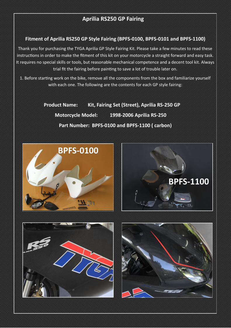
Aprilia RS250 GP Fairing
Fitment of Aprilia RS250 GP Style Fairing (BPFS-0100, BPFS-0101 and BPFS-1100)
Thank you for purchasing the TYGA Aprilia GP Style Fairing Kit. Please take a few minutes to read these
instructions in order to make the fitment of this kit on your motorcycle a straight forward and easy task.
It requires no special skills or tools, but reasonable mechanical competence and a decent tool kit. Always
trial fit the fairing before painting to save a lot of trouble later on.
1. Before starting work on the bike, remove all the components from the box and familiarize yourself
with each one. The following are the contents for each GP style fairing:
Product Name: Kit, Fairing Set (Street), Aprilia RS-250 GP
Motorcycle Model: 1998-2006 Aprilia RS-250
Part Number: BPFS-0100 and BPFS-1100 ( carbon)
BPFS-0100
BPFS-1100
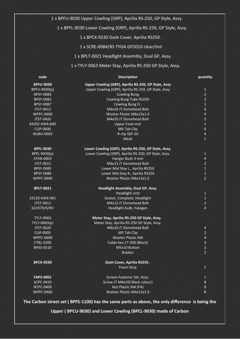
1 x BPFU-9030 Upper Cowling (GRP), Aprilia RS-250, GP Style, Assy.
1 x BPFL-9030 Lower Cowling (GRP), Aprilia RS-250, GP Style, Assy.
1 x BPCX-9230 Dash Cover, Aprilia RS250 .
1 x SCRE-0084/85 TYGA GP2010 clear/tint
1 x BPLT-0021 Headlight Assembly, Dual GP, Assy.
1 x TYLY-0063 Meter Stay, Aprilia RS-250 GP Style, Assy.
The Carbon street set ( BPFS-1100) has the same parts as above, the only difference is being the
Upper ( BPCU-9030) and Lower Cowling (BPCL-9030) made of Carbon
code Description quantity
BPFU-9030 Upper Cowling (GRP), Aprilia RS-250, GP Style, Assy BPFU-9030(p) Upper Cowling (GRP), Aprilia RS-250, GP Style, Assy 1
BPSY-0083 Cowling Bung 2 BPSY-0082 Cowling Bung Tube RS250 2 BPSY-0087 Cowling Bung Fr. 1 JTST-0612 M6x10 JT Domehead Bolt 6
WPPC-0600 Washer Plastic M6x13x1.0 9 JTST-0420 M4x20 JT Domehead Bolt 2
64202-KW6-840 Upper Cowl mat 1 CLIP-0600 M6 Tab Clip 6
NUBO-0003 R clip SSP-20 4 Mesh 1
BPFL-9030 Lower Cowling (GRP), Aprilia RS-250, GP Style, Assy. BPFL-9030(p) Lower Cowling (GRP), Aprilia RS-250, GP Style, Assy. 1
STHB-0003 Hanger Bush 3 mm 4 JTST-0615 M6x15 JT Domehead Bolt 2 BPSY-0085 Lower Mid Stay L., Aprilia RS250 1 BPSY-0086 Lower Mid Stay R., Aprilia RS250 1 WPPC-0600 Washer Plastic M6x13x1.0 2
BPLT-0021 Headlight Assembly, Dual GP, Assy.
Headlight Unit 1 33120-KW6-961 Socket, Complete, Headlight 1
JTST-0412 M4x12 JT Domehead Bolt 2 62337SVS/RV Headlight bulb, Halogen 4
TYLY-0063 Meter Stay, Aprilia RS-250 GP Style, Assy.
TYLY-0063(p) Meter Stay, Aprilia RS-250 GP Style, Assy. JTST-0620 M6x20 JT Domehead Bolt 4 CLIP-0005 M5 Tab Clip 2
WPPC-0600 Washer Plastic M6 4 CTBL-0200 Cable ties CT-200 (Black) 3 BHSS-0510 M5x10 Button 2
Rubber 2
BPCX-9230 Dash Cover, Aprilia RS250 . Foam Strip 1
FAPS-0001 Screen Fastener Set, Assy. 1 SCPC-0410 Screw JT M4x10( Black colour) 8 NTPC-0400 Nut Plastic M4 (PA) 8 WPPC-0400 Washer Plastic M4x12x1.0 8
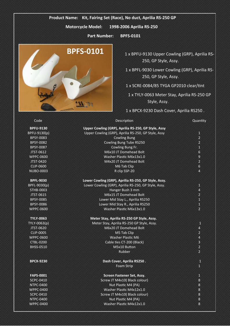
Product Name: Kit, Fairing Set (Race), No duct, Aprilia RS-250 GP
Motorcycle Model: 1998-2006 Aprilia RS-250
Part Number: BPFS-0101
1 x BPFU-9130 Upper Cowling (GRP), Aprilia RS-
250, GP Style, Assy.
1 x BPFL-9030 Lower Cowling (GRP), Aprilia RS-
250, GP Style, Assy.
1 x SCRE-0084/85 TYGA GP2010 clear/tint
1 x TYLY-0063 Meter Stay, Aprilia RS-250 GP
Style, Assy.
1 x BPCX-9230 Dash Cover, Aprilia RS250 .
Code Description Quantity
BPFU-9130 Upper Cowling (GRP), Aprilia RS-250, GP Style, Assy BPFU-9130(p) Upper Cowling (GRP), Aprilia RS-250, GP Style, Assy 1
BPSY-0083 Cowling Bung 2 BPSY-0082 Cowling Bung Tube RS250 2 BPSY-0087 Cowling Bung Fr. 1 JTST-0612 M6x10 JT Domehead Bolt 6
WPPC-0600 Washer Plastic M6x13x1.0 9 JTST-0420 M4x20 JT Domehead Bolt 2 CLIP-0600 M6 Tab Clip 6
NUBO-0003 R clip SSP-20 4
BPFL-9030 Lower Cowling (GRP), Aprilia RS-250, GP Style, Assy. BPFL-9030(p) Lower Cowling (GRP), Aprilia RS-250, GP Style, Assy. 1
STHB-0003 Hanger Bush 3 mm 4 JTST-0615 M6x15 JT Domehead Bolt 2 BPSY-0085 Lower Mid Stay L., Aprilia RS250 1 BPSY-0086 Lower Mid Stay R., Aprilia RS250 1
WPPC-0600 Washer Plastic M6x13x1.0 2
TYLY-0063 Meter Stay, Aprilia RS-250 GP Style, Assy. TYLY-0063(p) Meter Stay, Aprilia RS-250 GP Style, Assy. 1
JTST-0620 M6x20 JT Domehead Bolt 4 CLIP-0005 M5 Tab Clip 2
WPPC-0600 Washer Plastic M6 4 CTBL-0200 Cable ties CT-200 (Black) 3 BHSS-0510 M5x10 Button 2
Rubber 2
BPCX-9230 Dash Cover, Aprilia RS250 . 1 Foam Strip 1
FAPS-0001 Screen Fastener Set, Assy. 1 SCPC-0410 Screw JT M4x10( Black colour) 8 NTPC-0400 Nut Plastic M4 (PA) 8 WPPC-0400 Washer Plastic M4x12x1.0 8 SCPC-0410 Screw JT M4x10( Black colour) 8 NTPC-0400 Nut Plastic M4 (PA) 8 WPPC-0400 Washer Plastic M4x12x1.0 8
BPFS-0101

BPFU-9130 BPCU-9030 BPFU-9030
BPFL-9030 BPCL-9030 BPCX-9230
M6 Bolts, Washers and
Clips
TYLY-0063
BPSY-0087
BPLT-0021
Fairing Mounting Hardware Side Fairing Mounting
Hardware
Lower Mid Stays Screen Fasteners
Plastic Washers
Mesh
Clips
Aprilia parts to be (re) used

2. Remove the, mirrors, stock fairing, headlight, meter stay, lower stays and associated parts. You will be
reusing the mirrors and mounting hardware shown in the photo above so make sure they are in good
condition too.
3. Replace the stock meter stay with the TYGA one. It is installed in exactly the same way as the stock
one. secure to frame but leave bolts loose for now to allow for later adjustment. Fit instruments and wir-
ing harness using the original Aprilia mounting hardware. Connect electrical system and check everything
works. Attach the dash panel using hardware provided. There is strip of foam that can be used on the
leading rear edge to prevent damage to instrument cluster when installed. The dash can be adjusted
slightly to make sure it is straight before tightening. Use cable ties provided to tidy up wiring harness and
secure it to the meter stay.

4. The next job to do is to fit the headlight if you have the street set. Check the headlight works properly
by plugging it into the stock Aprilia harness. The headlight consists of two units which fits into the fairing
by way of a screw which screws through the headlight and into the fairing on the top and a screw under-
neath which screws into the headlight. Remove the harness and bulbs so you can fit the headlights inde-
pendently. Remove the screws in the headlight and the headlight mounting position in the fairing and
place one headlight unit in the fairing making sure the tabs are locating properly. Then turn the fairing
over and fit the screw through the hole and into the headlight housing. When this is completed, do the
same for the other side. Replace the bulbs and harness and this part is now down. While you are here,
check the mesh fits over the front air duct. Only secure it after paintwork is completed because this will
make the painting easier and avoid overspray on the mesh. the same is true also for the foam around the
headlight to reduce glare inside the fairing. attach it last after painting.

5. On the street set, you need to fit the mirrors to the upper fairing in the same way they fit the stock
bike except with the addition of a rubber piece between the stock plastic Aprilia mirror housing and the
fairing as shown in the photo. The mirror housings will later be mounted to the meter stay to secure
them.
6. The screen is next. The fitting is straight forward but you do need to take care no to scratch it and for a
trial fit it may be better to leave it in the plastic bag rather than risk mounting it and then removing it.
However, the procedure is to fit loosely a screen fastener (consisting of a plastic bolt through from the
outside with a washer and nut on the inside) to one of the rear corners . Do the same for the other cor-
ner. The do the two front positions and finish off with the two middle positions. This will minimise
scratching because acrylic against glass fibre is no contest! You can then push and pull the screen around
because the holes are slotted to find the optimum position before tightening. Be careful not to overtight-
en the plastic screws. If there seems to be a small gap between screen and fairing, this can generally be
ironed out by loosening the screws and re-tightening, while squeezing the components together at the
gap. .
7. Next thing to do is the mounting points. There are three plastic bungs. You will notice one is slightly
longer than the other two and this fits on the inside of the front mounting hole above the headlight and
is secured using the M6 bolt and plastic washer provided. This bung will later locate in the front of the
meter stay. The other two plastic cowling bungs are used in the side positions. You will see there are also
two tubes. Fit the tubes and bungs as shown in the photos using the R clips. The fairing will need to be
drilled and the bungs mounted but that is a later job.
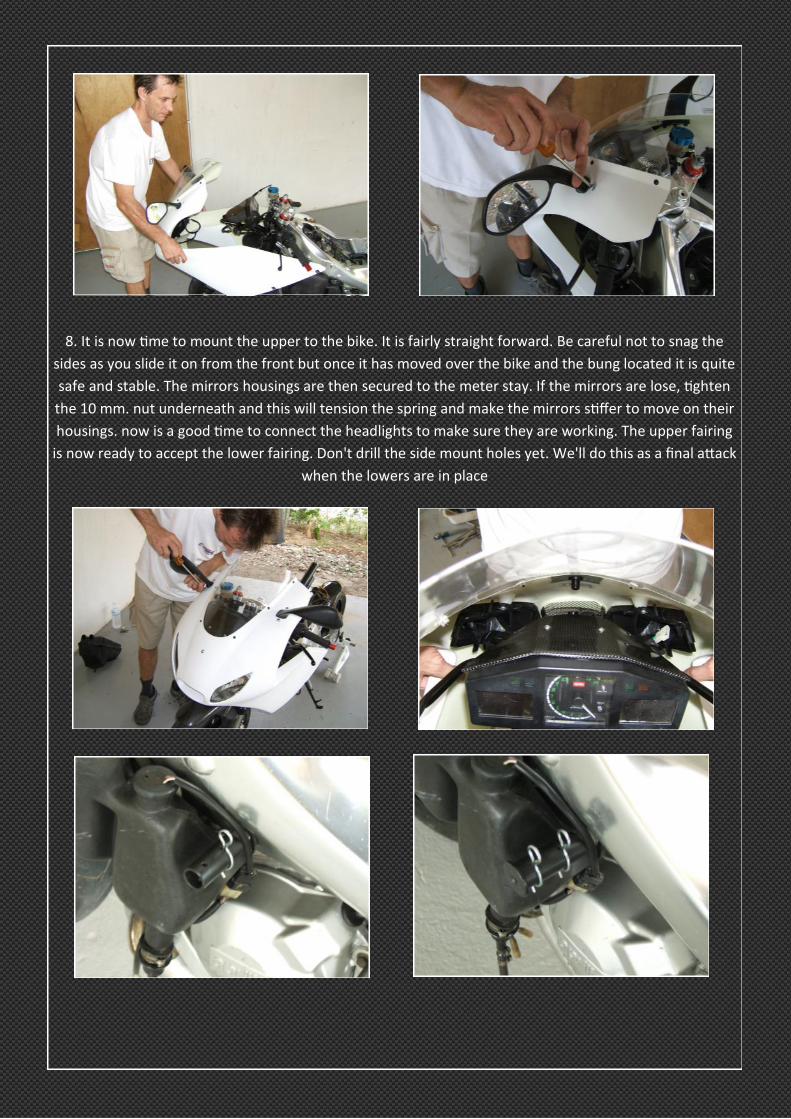
8. It is now time to mount the upper to the bike. It is fairly straight forward. Be careful not to snag the
sides as you slide it on from the front but once it has moved over the bike and the bung located it is quite
safe and stable. The mirrors housings are then secured to the meter stay. If the mirrors are lose, tighten
the 10 mm. nut underneath and this will tension the spring and make the mirrors stiffer to move on their
housings. now is a good time to connect the headlights to make sure they are working. The upper fairing
is now ready to accept the lower fairing. Don't drill the side mount holes yet. We'll do this as a final attack
when the lowers are in place

9. Before mounting the lower fairing, attention now needs to be focused on the mounting points. There
are two lower mid stays. These fit as shown in the photo and replace the stock Aprilia ones. Their pur-
pose is to allow for adjustments of the fairing to prevent it touching the exhaust system. These can be
adjusted later or even removed if not required. also check to make sure your bike has the rear lower
stays mounted. There are 4 hanger bushes 3 mm thick which can be used as required to space compo-
nents to get the necessary clearance on components. Have them on standby read to use. The side stand
will slide through the hole in the lower and there is not much clearance. First thing is to check the spring
is mounted as shown in the photo with the shaft of the spring at the rear of the mounting tab at the top.
If it is mounted with the shaft at the front it will snag on the fairing when the side stand is deployed. if
you are worried about scratching the fairing or sidestand use sock technology and slide a sock over the
side stand during the lower fairing mounting to prevent and scratches!
10. Now is the time to mount the lower fairing sliding it through the bike from the left side with the side
stand deployed and going through the hole first. Be careful not to snag on anything and it is very helpful
if you have an assistant during this phase to hold one side while you secure the other. The M6 bolts and
plastic washers are used to mount it to the upper and the two rear positions making a total of 8 posi-
tions. Be careful that the front part near the radiator is correctly aligned before securing the bolts.
This lower cowling is very different to the one it replaces so don't expect it to immediately bolt into place
with no issues. The main points are the exhaust chamber clearance, the foot controls and the sidestand
which are all in close proximity to the TYGA lower cowling. The challenge is to mount the lowers with
minimum or no modifications and to do this we suggest you do the following: a. Put the bike on a pad-
dock stand or as high off the ground as you can. Best to do this when fitting the upper but very worth-
while for the lowers. If you are retaining the sidestand, check to see if it is worn. You can do this by rock-
ing the leg in and out, not rotating it and most have a lot of free play where the pivot has worn. What
happens is the spring will pull the sidestand away from the bike so the more worn the less issues here! If
there is a clearance issue We suggest that you consider cutting and grinding smooth the part of the
casting which is on the tip of the leg which will hit the lower cowling first. This will give you a cm or so
extra clearance at the cost of not being able to park on boggy soil. Another thing you can do is place a
washer on the front mounting bolt sandwiched between the frame and the side stand. When the side-
stand is mounted it will then rotate outwards slightly without being visually noticeable and compromising
looks or function. Another fix is to build up the final stop on the side stand so it doesn't rotate as far. You
can build this with weld and then grind back for an optimum position. Of course, many of these things are
not needed depending on the exhausts and the wear of the sidestand but they are worth noting just in
case and we would certainly recommend the washer fix as a matter of course as it is quick, easy and re-
versible. It may be necessary to bend the left side lower rear fairing mount (the one on the left foot hang-
er) or space out the hanger if there is a chamber exiting this side.
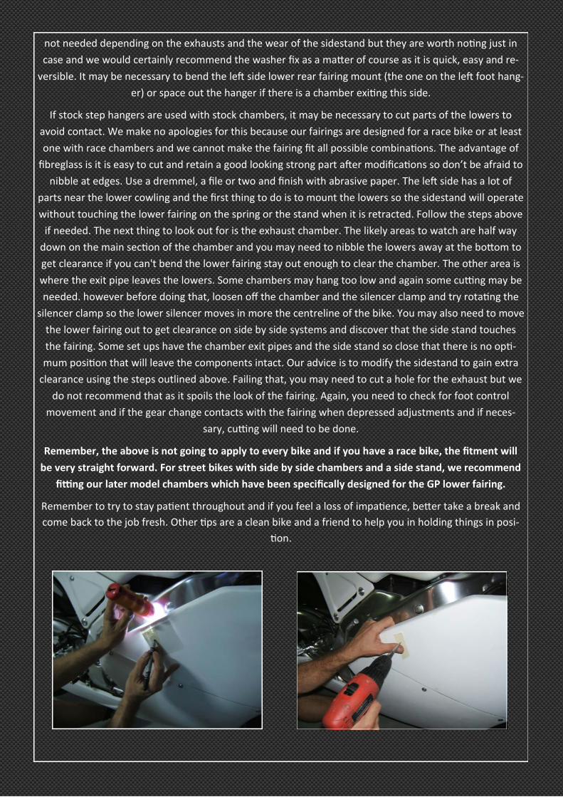
If stock step hangers are used with stock chambers, it may be necessary to cut parts of the lowers to
avoid contact. We make no apologies for this because our fairings are designed for a race bike or at least
one with race chambers and we cannot make the fairing fit all possible combinations. The advantage of
fibreglass is it is easy to cut and retain a good looking strong part after modifications so don’t be afraid to
nibble at edges. Use a dremmel, a file or two and finish with abrasive paper. The left side has a lot of
parts near the lower cowling and the first thing to do is to mount the lowers so the sidestand will operate
without touching the lower fairing on the spring or the stand when it is retracted. Follow the steps above
if needed. The next thing to look out for is the exhaust chamber. The likely areas to watch are half way
down on the main section of the chamber and you may need to nibble the lowers away at the bottom to
get clearance if you can't bend the lower fairing stay out enough to clear the chamber. The other area is
where the exit pipe leaves the lowers. Some chambers may hang too low and again some cutting may be
needed. however before doing that, loosen off the chamber and the silencer clamp and try rotating the
silencer clamp so the lower silencer moves in more the centreline of the bike. You may also need to move
the lower fairing out to get clearance on side by side systems and discover that the side stand touches
the fairing. Some set ups have the chamber exit pipes and the side stand so close that there is no opti-
mum position that will leave the components intact. Our advice is to modify the sidestand to gain extra
clearance using the steps outlined above. Failing that, you may need to cut a hole for the exhaust but we
do not recommend that as it spoils the look of the fairing. Again, you need to check for foot control
movement and if the gear change contacts with the fairing when depressed adjustments and if neces-
sary, cutting will need to be done.
Remember, the above is not going to apply to every bike and if you have a race bike, the fitment will
be very straight forward. For street bikes with side by side chambers and a side stand, we recommend
fitting our later model chambers which have been specifically designed for the GP lower fairing.
Remember to try to stay patient throughout and if you feel a loss of impatience, better take a break and
come back to the job fresh. Other tips are a clean bike and a friend to help you in holding things in posi-
tion.
11. This next phase is best done in dark or near dark conditions. test the headlight beam alignment on
high and dip and it should be close to the correct position. Adjust the position by pulling the upper fairing
up or pushing it down with the meter stay to frame mounting bolts loose until you find the correct head-
light beam position. (Some headlight adjustment can be done by slotting the lower headlight hole in the
fairing but this is minimal. Remember that suspension changes such as ride height or different compo-
nents will affect the stance of the bike and the headlight beam with the ground.)
When you are certain you have the position you want, tighten the meter stay mounting bolts. Now you
can go back to the side mounting stays. The holes for mounting the side bungs in the upper need to be
drilled. To mark out the screw position, hold the cowling up against the bung and then shine a torch at
the shiny frame which will reflect the light from the torch to the inside area around the bung. Look from
the outside and you will see the point of interference as a shadow. Mark this point with a magic marker
and then drill through with a 3 mm. drill bit. Offer up the side cowl again to check position. It may need
tweaking a little. Final hole size should be 6.5 mm.. Tighten the side cowl. Now check headlight adjust-
ment to confirm that it's within the parameters required. Check to see that all the other clearances with
chambers, side stand and foot controls are still ok and adjust as necessary.
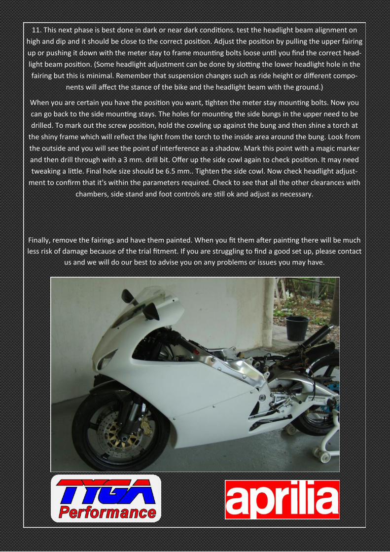
Finally, remove the fairings and have them painted. When you fit them after painting there will be much
less risk of damage because of the trial fitment. If you are struggling to find a good set up, please contact
us and we will do our best to advise you on any problems or issues you may have.
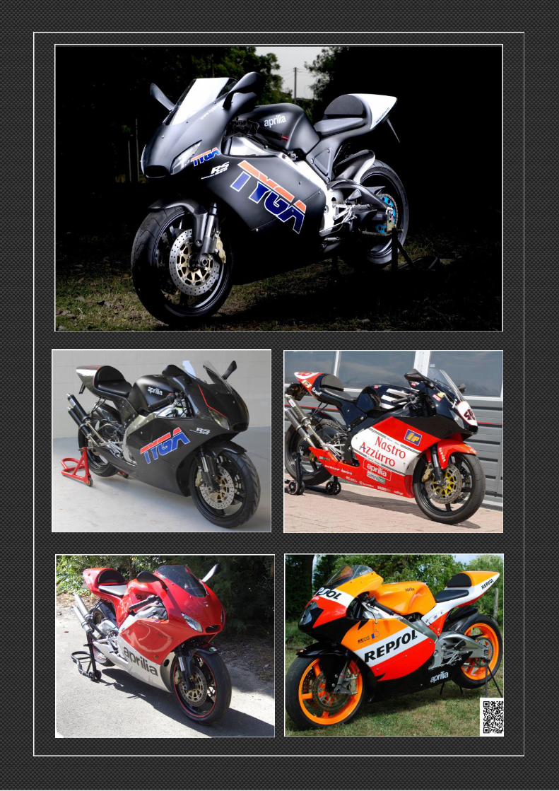

Check out our other Aprilia RS250 products
![Multiplicadores Interindustriales de PRgis.jp.pr.gov/Externo_Econ/Multiplicadores/Multiplicadores... · P ] µ o µ í X î ì î í ì X ì í í õ ì X ì ì ó ó ì X ì ì ó](https://img.dokumen.tips/doc/110x75/5bff9a9a09d3f2c9268c38be/multiplicadores-interindustriales-de-prgisjpprgovexternoeconmultiplicadoresmultiplicadores.jpg)


![o v } ] D v P µ o ] ( ] ] o o ^ } ] ] } v µ o v Ì · o ( } X u } o v À v P X } u ï ì í ñ ñ ñ í ñ í ì í ì î ì í ì í ì](https://img.dokumen.tips/doc/110x75/5e5db6577e68ce6818510ad2/o-v-d-v-p-o-o-o-v-o-v-oe-o-x-u-o-v-v-p-x-.jpg)


![^ /D^ D v µ o D X/D^ X ì ì ì ì í r ì í í · D X/D^ X ì ì ì ì í r ì í í E u s o ] ] } v W Ç W o o ] } v < ZZ s o ] î ñ l ì ð l î ì í õ s ] ( ] Ç W v v ]](https://img.dokumen.tips/doc/110x75/5e6b120b2868a730a95c7c3b/-d-d-v-o-d-xd-x-r-d-xd-x-r-.jpg)

![: X UW Z U W · e Á z } l u î ì î ì u î ì í ô u î ì í ñ u î ì í ï u î ì í í u î ì ì õ u î ì ì ó u î ì ì ð u î ì ì í u í õ õ ô x ^ ] o v U](https://img.dokumen.tips/doc/110x75/5e8122efcfc03f7ea4415448/-x-uw-z-u-w-e-z-l-u-u-u-u-.jpg)


![[2019.03]ì ì ì ë¬¸ì ¸í °ë · í ì ¬ì ê° ì (KOR)€¦ · Microsoft PowerPoint - [2019.03]ì ì ì ë¬¸ì ¸í °ë ·_í ì ¬ì ê° ì (KOR).pptx Author: freshj](https://img.dokumen.tips/doc/110x75/5f7278849163c419dd65e175/201903-kor-microsoft-powerpoint.jpg)


![W } u } ] } v î ì í ò r î ì í ó î ì í î l î ì í ï D](https://img.dokumen.tips/doc/110x75/62919f005b36720f4f4598f9/w-u-v-r-.jpg)

