Embed Size (px)
Citation preview

First Mobile Telephone System
First Mobile Telephone Service (MTS) was
introduced in 1946, St Loius.
Only three radio channels were available.
Call set-up required manual operation
In 1964 Improved Mobile Telephone (IMTS)
Service was introduced with additional channels
and more automatic handling of calls
First Mobile Telephone System
One and only one
high power base
station with which all
users communicate.
Entire Coverage
Area
Normal
Telephone
System
Wired connection

Draw back of conventional Mobile Telephone
Systems ?
Limitations on conventional mobile telephone systems.
Limited Service Capability
Poor Service Performance
Inefficient Frequency Spectrum Utilization
Technology and service affordability

cellular concept ..
In December 1947, Douglas H.Ring and W. Ray
Young, Bell Labs engineers, proposed hexagonal cell
concept for mobile phones.
The coverage region is divided into small cells
At this stage the technology to implement the ideas did not
exist nor had the frequencies allocation
In 1960s Bell Labs developed the electronics to achieve
this concept.
In 1970s ,the concepts of frequency reuse and handoff, as
well as a number of other concepts that formed the basis of
modern cell phone technology, were described.
In December 1971, AT&T submitted a proposal for
cellular service to the FCC.
After years of hearings, the FCC approved the
proposal in 1982 for Advance Mobile Phone System
(AMPS)
AMPS was analog in nature and called 1G.
Later AMPS was eventually superseded by Digital
AMPS in 1990.

First Mobile Cellular System
The technological development that make special
the 1G mobile phones from the previous
generation was the use of Multiple cell sites,
Ability to transfer calls from one site to the next as
the user travelled between cells during a
conversation.

Cellular Concept : An Idea which gave 1G
mobile cellular system
Replace high power transmitter with several low power transmitters to create small “cells” Multiple low-power base stations ,service mobile
users within their coverage area
Each cell assigned a set of frequencies
Neighboring cells assigned different group of frequencies to reduce adjacent-cell interference
Handoff users to neighboring base stations as users move.

First Generation (1G) Cellular System

IG (AMPS)Configuration Analog in nature
Uses FDD scheme
Down link frequency = 869-894 MHz
Uplink frequency = 824-849 MHz
Spacing between forward and reverse channel = 45 MHz
Channel bandwidth = 30 kHz
Number of full-duplex voice channels = 790
Number of full duplex control channels = 42
Data transmission rate = 10 kbps
Cell size = 2-20km radius

Second Generation (2G) Cellular System
In 1990, the 2G mobile phone systems
emerged, primarily using the GSM standard.
2G differed from the 1G by using digital instead
of analog transmission
In 1991 the first GSM network launched in
Finland.

2G Cellular Telephone Standard
Global System for Mobile (GSM) Interim Standard 136 (IS-136) Interim Standard 95 (IS-95)

Cellular Standards Evolution
Japan Europe Americas
TACS NMT/TACS/Other AMPS
PDC GSM TDMA CDMA
1st Gen
2nd Gen

GLOBAL SYSTEM FOR MOBILE
COMMUNICATION (GSM)
In 1982, European Conference of Postal and Telecommunications Administrations (CEPT) created the Group Spécial Mobile committee for developing a European standard for digital cellular voice telephony
1986 the European Commission proposed reserving the 900 MHz spectrum band for GSM.
1987, 15 representatives from 13 European countries signed a MoU in Copenhagen to develop and deploy a common cellular telephone system across Europe.
In 1989, the Groupe Spécial Mobile committee was transferred from CEPT to the European ETSI
Phase I of the GSM specifications were published in 1990.
In 1991 work begin to expand the GSM standard to 1800 MHz frequency band
In 1993 the first 1800 MHz network became operational in the UK .

July 1, 1991 The world's first GSM call was made by the former Finnish prime minister Harri Holkeri,
1992, the first SMS or "text message" was sent In 1992 Vodafone UK and Telecom Finland signed the first
international roaming agreement In 1995, fax, data and SMS messaging services were
launched commercially In 1995 the first 1900 MHz GSM network became
operational in the U.S. In 1996 Pre-paid GSM SIM cards were launched. In 2000, the first commercial GPRS services were
launched In 2002, MMS and the first GSM network in the 800 MHz
frequency band introduced. In 2003,EDGE services first became operational in a
network
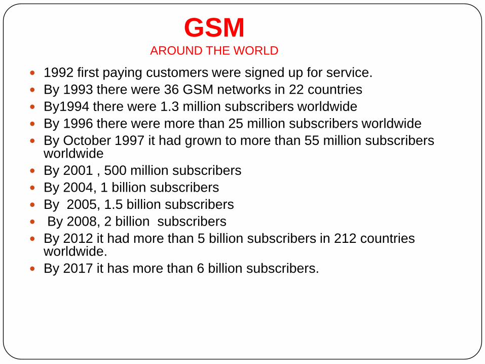
1992 first paying customers were signed up for service.
By 1993 there were 36 GSM networks in 22 countries
By1994 there were 1.3 million subscribers worldwide
By 1996 there were more than 25 million subscribers worldwide
By October 1997 it had grown to more than 55 million subscribers worldwide
By 2001 , 500 million subscribers
By 2004, 1 billion subscribers
By 2005, 1.5 billion subscribers
By 2008, 2 billion subscribers
By 2012 it had more than 5 billion subscribers in 212 countries worldwide.
By 2017 it has more than 6 billion subscribers.
GSM AROUND THE WORLD

GSM (2G) GSM is a 2G cellular standard developed to cater voice and
data delivery services using digital modulation.
Properties of 2G mobile system
Good subjective speech quality
Low terminal and service cost
Support for international roaming
Ability to support handheld terminals
Support for range of new services and facilities
Enhanced Features
ISDN compatibility
Enhance privacy
Security against fraud
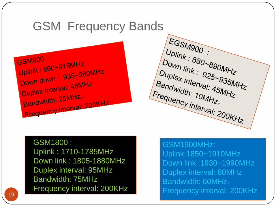
GSM Frequency Bands
19
GSM1800 :
Uplink : 1710-1785MHz
Down link : 1805-1880MHz
Duplex interval: 95MHz
Bandwidth: 75MHz
Frequency interval: 200KHz
GSM1900MHz:
Uplink:1850~1910MHz
Down link :1930~1990MHz
Duplex interval: 80MHz
Bandwidth: 60MHz,Frequency interval: 200KHz

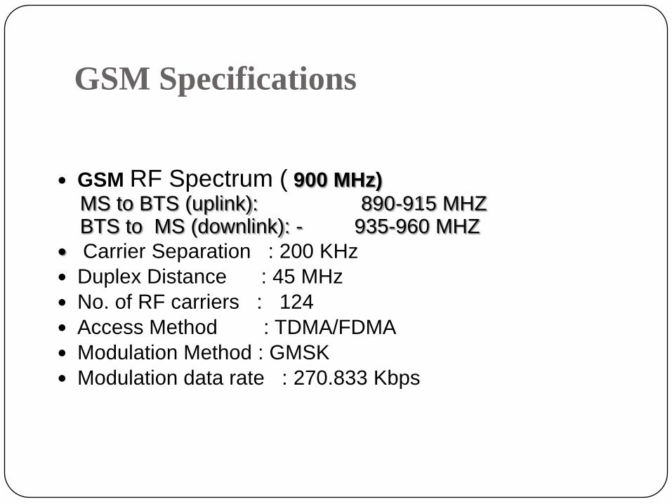
GSM Specifications
GSM RF Spectrum ( 900 MHz)MS to BTS (uplink): 890-915 MHZBTS to MS (downlink): - 935-960 MHZ
Carrier Separation : 200 KHz
Duplex Distance : 45 MHz
No. of RF carriers : 124
Access Method : TDMA/FDMA
Modulation Method : GMSK
Modulation data rate : 270.833 Kbps
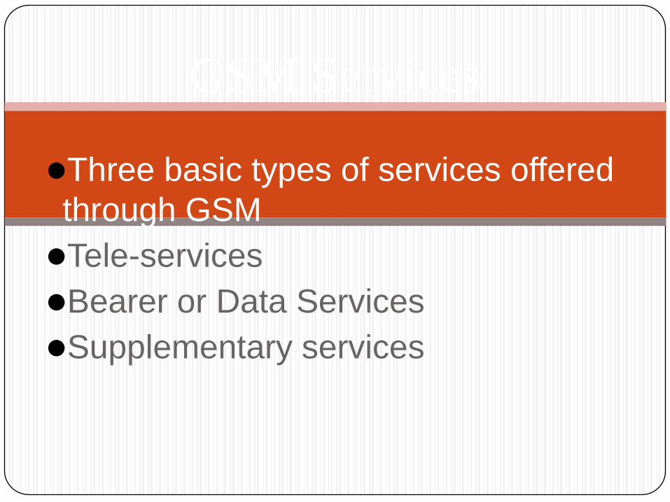
Three basic types of services offered
through GSM
Tele-services
Bearer or Data Services
Supplementary services
GSM Services
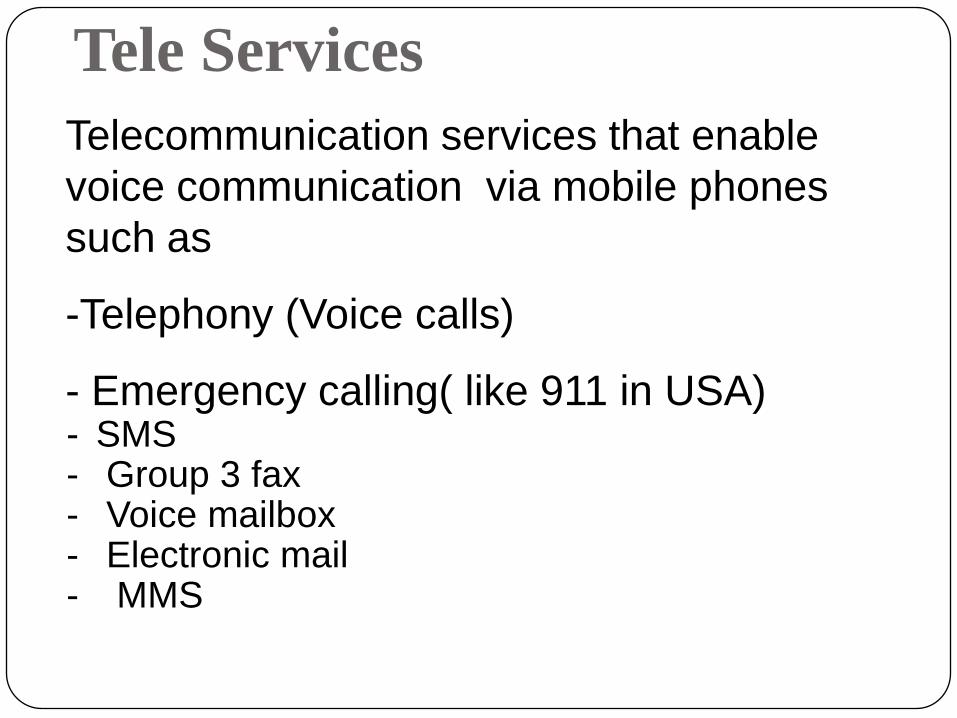
Tele Services
Telecommunication services that enable
voice communication via mobile phones
such as
-Telephony (Voice calls)
- Emergency calling( like 911 in USA)- SMS - Group 3 fax- Voice mailbox- Electronic mail- MMS
Bearer Services
Include various data services for information transfer between GSM and other networks like PSTN, ISDN etc at rates from 300 bps to 9.6 kbps
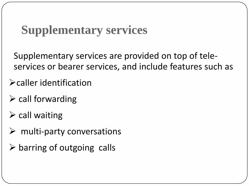
Supplementary services
Supplementary services are provided on top of tele-services or bearer services, and include features such as
caller identification
call forwarding
call waiting
multi-party conversations
barring of outgoing calls

GSM Architecture
PSTN
Data Terminal
HLR/VLR
MSCBSC
OMC(Operation & Maintenance
Center)
OperationTerminal
BTS
HandsetA
X.25
A-bisSS7
Network sub-system PSTNRadiosub-system
Mobilestation
UM
SIMcard
AUC/EIR

Base Station Subsystem is composed of following
parts
1. Base Station Controller (BSC)
2. Base Transceiver Station (BTS)

Base Station Controller (BSC)
Communicate with MSC and BTS
Most robust element in the BSS
Provides, the intelligence behind the BTS.
has 16 to 512 of BTS under its control.
One BSC Support ( 20000- 45000 ) subscriber
Function of Base Station Controller
(BSC)
Manages Radio resources for BTS ( Assigns Frequency and time slots for all MS’s in its area )
Handle call set up
Provide Handover to MS
Control Radio Power
Transcoding and rate adaptation functionality

BSC

Typical GSM BTS
What a GSM cell site consist
A Shelter
Tower

BTS Shelter Layout
AC-2
AC-1
DDF
BTS
Cabinet
PIU
SMPS Battery
Bank
DO
OR
MCB1
MCB2

Types of Tower
Ground Base Tower(GBT)
Roof Top Tower(RTT)
In Building Solution(IBS)

Types of BTS
Ultra wave BTS
Flexi BTS
Ultra Wave BTS
can support max. of 12 TRx card.
One TRx card supports 8 time slots( i.e. max of 8 users),
Capacity in terms of users can be increased using Half
rate, ( one time slot is assigned to 2 users in Half rate)
It has all Pin connections on back side

Ultra wave BTS

Flexi BTS
Flexi can support max. of 24 TRx.
Easier site construction, with easier implementation
lower installation costs
Reduced demand for power, resulting in smaller power systems
All connections are on front side so it is easy to install every equipment.

FLEXI BTS
NOKIA BTS CABINET 4X4X4
CONFIGURATION

NOKIA BTS CABINET 4X4X4 CONFIGURATION
DVJA
M2HA
M2HA
M2HA
M2HA
M2HA
TRX-0
TRX-6
TRX- 9
TRX-10
TRX-11
TRX-7
TRX-8
TRX-5
TRX-1
TRX-3
TRX-4
TRX-2
M2HA
DVJA
DVJA
DVJA
DVJA
DVJA
BIO
A
PW
SB
PS
WB
PW
SB
BB
F1
BB
F2
BB
F3
BB
F4
BB
F5
BB
F6
VxR
B
VxR
B
VxR
B
VxR
B
Β
Sector
α
Sector
¥
Sector
WCHA
WCHA
WCHA
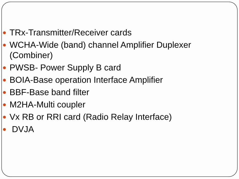
TRx-Transmitter/Receiver cards
WCHA-Wide (band) channel Amplifier Duplexer
(Combiner)
PWSB- Power Supply B card
BOIA-Base operation Interface Amplifier
BBF-Base band filter
M2HA-Multi coupler
Vx RB or RRI card (Radio Relay Interface)
DVJA

Transceiver (TRX)
Basically does transmission and reception of signals. Sending and reception of signals to/from higher network
entities (like the BSC) Can support 8 user at a time in Ultra BTS and 24 users in
Flexi BTS - Prize 1 Lac approx

BOIA-Base operation Interface Amplifier
- Power amplifier
-Brain of BTS
-Amplifies the signal from TRX for transmission through antenna; may be integrated with TRX.
-Support 2TRx

WCHA-Wide band Amplifier Duplexer
It works as a Combiner
Combines feeds from several DRXs so that they could be sent out through a single antenna
allows for a reduction in the number of antenna used.

Base Band Filter(BBF)
Filter baseband signal coming from user
Frequency hopping, signal DSP, etc.. Support 2 TRx

Dual Variable Gain Amplifier(DVGA)
The filtered input signal is level controlled using a variable
gain amplifier (VGA) or a variable attenuator and amplifier
combination.
The signal is then sent to a demodulator RF integrated
circuit (RFIC) where it is demodulated into in-phase (I) and
quadrature phase (Q) baseband signals.
Network Switching Subsystem
(NSS)
NSS carries out switching functions and manages the communications between MS and the PSTN.
It is owned and deployed by mobile phone operators

Function of Network switching subsystem
(NSS)
Nerve Centre of entire GSM network
Manages all call processing subscriber
related functions
Contains
the core switching component
a number of databases
Gateways to other networks
Uses Signaling System Number 7 (SS7)

Components of NSS Network ?
NSS contains following nodes
MSC
VLR
HLR
AUC
EIR
Mobile Switching Center (MSC)
Heart of the network
Manages communication between GSM and other networks
Call setup function and basic switching
Call routing
Billing information and collection
Mobility management
- Registration
- Location Updation
- Inter BSS and inter MSC call handoff
MSC does realize these functions with conjunction of following 4 intelligent data base HLR
VLR
EIR
AUC

Home Location Registers (HLR)
Contains the administrative information of each of the subscriber registered in the network
Keep permanent copy of the subscriber data
Logically one HLR per PLMN,
HLR maps each IMSI with a unique mobile phone number called Mobile Subscriber ISDN (MSISDN).
HLR also holds most of the information held by the SIM such as IMSI, MSISDN, prepaid/postpaid, roaming restrictions, supplementary services etc.

Visitor Location Registers (VLR)
Temporary database which updates whenever
new MS enters its area, by HLR database
Controls those mobiles roaming in its area
Database contains IMSI, TMSI, MSISDN,
MSRN, Location Area, authentication key

Authentication Center (AUC)
AuC is a function to authenticate each SIM
card that attempts to connect to the GSM core
network
After successful authentication , HLR is
allowed to manage the SIM and services
Protects against intruders in air interface
Maintains authentication keys and algorithms
and provides security triplets ( RAND,
SRES,Kc)
Generally associated with HLR

Equipment Identity Register (EIR)
- Database that is used to track handsets
using the IMEI (International Mobile
Equipment Identity)
- Made up of three sub-classes: - The White List,
- The Black List
- The Gray List
- Only one EIR per PLMN
Other Network Components
Operations & Maintenance Subsystem(OMS)
Enhanced Services Subsystem (ESS)

Critical :-Immediate action
Major :- As soon as possible
Minor :- Action can be taken when there is time
Warning :-Point out conditions and corrective
Action is then taken during schedule maintenance
Indeterminate :- shows that an alarm has been
Generated for which there is no alarm severity
In the system.?

OMS
OMS is used to configure, control and to
monitor the GSM network.
It comprises of two parts:
Operation and Maintenance Centre - Switch
Operation and Maintenance Centre - Radio
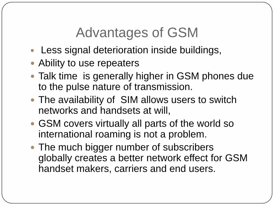
Advantages of GSM
Less signal deterioration inside buildings,
Ability to use repeaters
Talk time is generally higher in GSM phones due to the pulse nature of transmission.
The availability of SIM allows users to switch networks and handsets at will,
GSM covers virtually all parts of the world so international roaming is not a problem.
The much bigger number of subscribers globally creates a better network effect for GSM handset makers, carriers and end users.

Disadvantages of GSM
Interferes with some electronics, especially certain audio
amplifiers.
Intellectual property is concentrated among a few
industry participants, creating barriers to entry for new
entrants and limiting competition among phone
manufacturers.
GSM has a fixed maximum cell site range of
120 km, which is imposed by technical limitations
This is expanded from the old limit of 35 km.
PSTN
HLR/
VLR
MSCBSC
BTS
MS
SS7GMSC1
10
1 23 4
5 6
7899
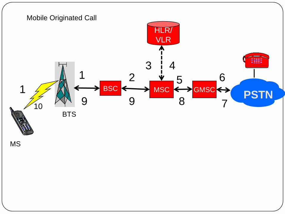
Mobile Originated Call
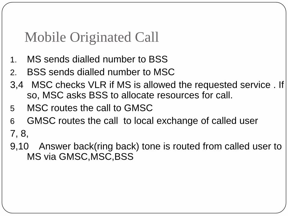
Mobile Originated Call
1. MS sends dialled number to BSS
2. BSS sends dialled number to MSC
3,4 MSC checks VLR if MS is allowed the requested service . If so, MSC asks BSS to allocate resources for call.
5 MSC routes the call to GMSC
6 GMSC routes the call to local exchange of called user
7, 8,
9,10 Answer back(ring back) tone is routed from called user to MS via GMSC,MSC,BSS

PSTN
HLR/AUC
MSCBSC
MS
SS7GMSC
1
3
4
5
27
9
VLR
68
10
11
12
13
14 15
16
10
13
17
Mobile Terminated Call

Mobile Terminated Call1. Calling a GSM subscribers
2. Forwarding call to GSMC
3. Signal Setup to HLR
4. 5. Request MSRN from VLR
6. Forward responsible MSC to GMSC
7. Forward Call to current MSC
8. 9. Get current status of MS
10.11. Paging of MS
12.13. MS answers
14.15. Security checks
16.17. Set up connection
CDMA (Code Division Multiple Access)

Limitations of conventional FDMA and TDMA
Each channel is allocated a disjoint frequency or time slot
Channel capacity is limited by BW and time allotment, thermal
AWGN, and propagation effect (shadowing and multipath fading)
Frequency reuse needs a very careful design because of potential
co-channel interference.
FDMA and TDMA suffer degradation due to multipath fading

Spread Spectrum multiple access can overcome most of the
limitations of conventional systems.
Fast Network deployment.
Reduced service interruptions
Low Maintenance & operational cost
Better system coverage flexibility
Higher capacity
Anti-jamming (A/J) & Anti Interference (A/I)
Resistance to interception
Message Privacy
ADVANTAGES OF CDMA

Advantages of CDMA
Capacity is biggest asset; it can accommodate more users per MHz
of bandwidth than any other technology.
Has no built-in limit to the number of concurrent users.
Consumes less power and covers large areas so cell size in IS-95 is
larger.
Able to produce a reasonable call with lower signal (cell phone
reception) levels.
Uses soft handoff, reducing the likelihood of dropped calls.

What is CDMA ?
CDMA is a wireless communications Access
technique that uses the principle of spread spectrum .
Users are separated by codes.

WHAT IS MULTIPLE ACCESS ?
NUMBER OF USERS ACCESS AND SHARE
• TRANSMISSION MEDIUM
• BANDWIDTH AVAILABLE
FOR COMMUNICATION AT THE SAME TIME.

Multiple Access scheme
72

CDMA Evolution 1Gbps
153.6kbps
CDMA
1xRTT
CDMA
1xEV-DV
CDMA
IS-95
CDMA
1xEV-DO
2G 2.5G3G
9.6kbps
4G
2Mbps4G
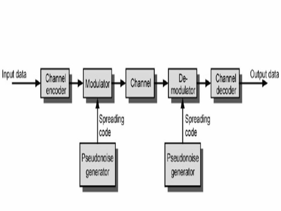
What is Spread Spectrum A means of transmission in which the data
occupies a B.W in excess of the minimum bandwidth necessary to send it.
Signal spreading is done before transmission by using a spreading sequence.
The same sequence is used at the receiver to retrieve the signal


SPREAD SPECTRUM CAPACITY
SS Capacity can be calculated by Shannon’s Equation
C= W Log (1+S/N)
Where C=Capacity (bps)
W=Bandwidth
S=Signal Power
N=Noise Power
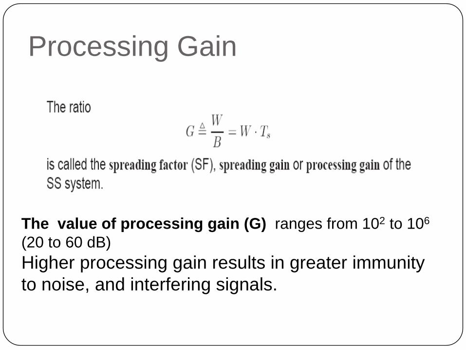
Processing Gain
The value of processing gain (G) ranges from 102 to 106
(20 to 60 dB)
Higher processing gain results in greater immunity
to noise, and interfering signals.

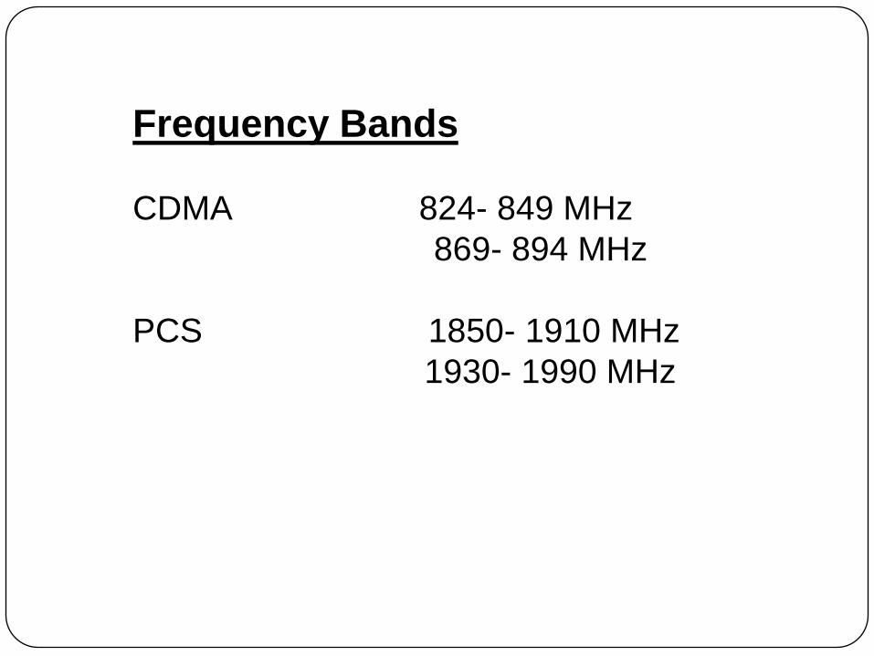
Frequency Bands
CDMA 824- 849 MHz
869- 894 MHz
PCS 1850- 1910 MHz
1930- 1990 MHz
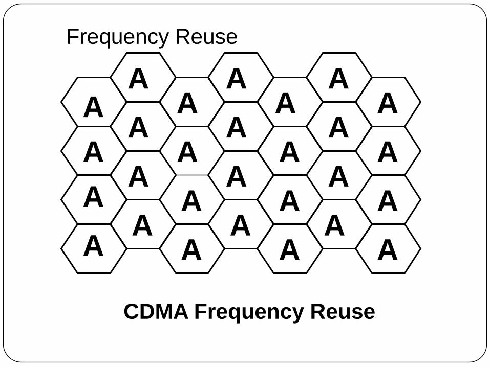
A
A
A
AA
A
A
AA
A
A
AA
A
A
AA
A
A
AA
A
A
A
AA
A
A
CDMA Frequency Reuse
Frequency Reuse
C
D
B
AC
F
G
EB
A
E
GB
D
C
FE
G
F
CE
B
D
C
FD
B
A
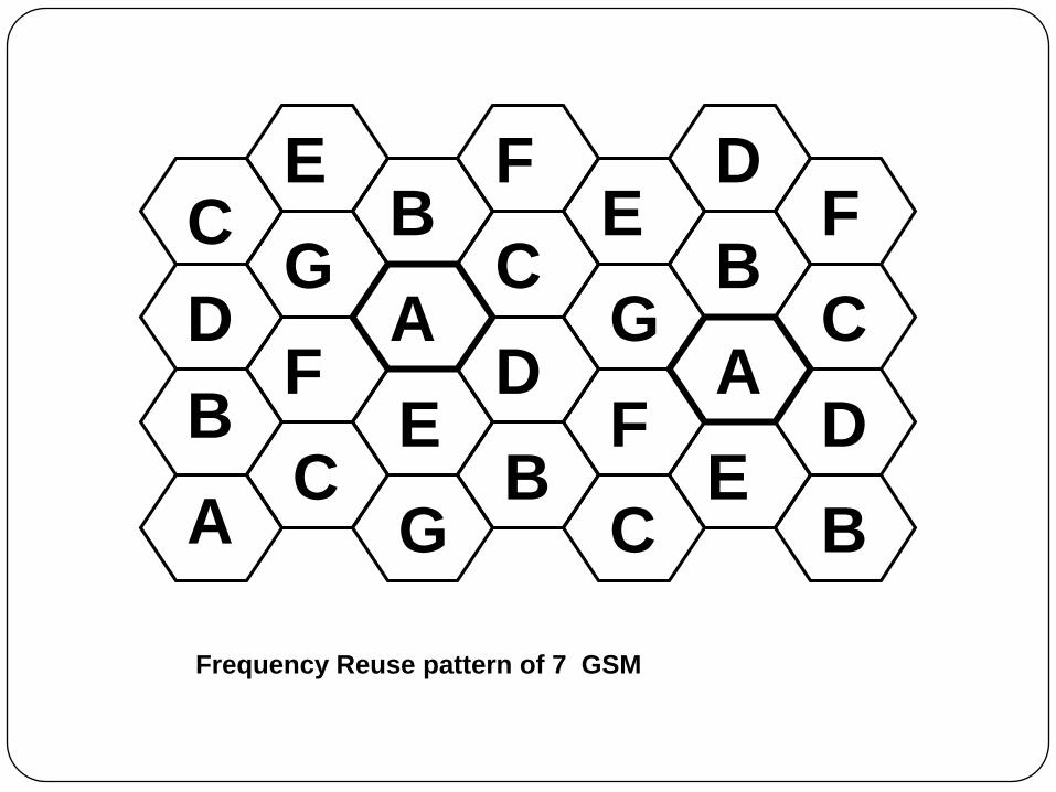
Frequency Reuse pattern of 7 GSM
Anti-Jamming (A/J) & Anti Interference
(A/I)
Real beauty of SS.
Intentional or un-intentional interference and jamming
signals are rejected without the right key .
Only the desired signal, which has the key, will be seen
at the receiver when de-spreading operation is
exercised.
Spread Spectrum Principle
The signal spread on a bandwidth much
greater than that which is necessary to
send the information or data with the
help of spreading code .
84

Spreading Codes ?
A noise-like and random signal
Generated at the transmitter.
The same signal must be generated at the receiver in
synchronization.
Spread and de-spread with the matched code results in
detection
Spread and de-spread with the wrong code results in
interference
The code must satisfy some properties

Assume a sequence
S={(000111101011001),(010011010111100)}
Balance property:-Relative frequencies of “0”
and “1” should be ½
Run Property: Run lengths of zeros and ones
should be
Half of all run lengths should be unity
One - quarter should be of length two
One - eighth should be of length three

Correlation
The concept of determining how much similarity one set of data has with another
Range between –1 and 1
1 The second sequence matches the first sequence
0 There is no relation at all between the two sequences
-1 The two sequences are mirror images

Cross correlation
The comparison between two sequences from different sources rather than a shifted copy of a sequence with itself
Cross-correlation is a measure of similarity of two waveforms as a function of a time-lag applied to one of them.
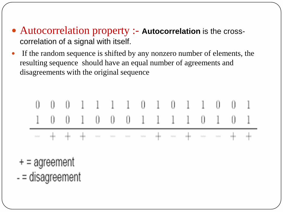
Autocorrelation property :- Autocorrelation is the cross-
correlation of a signal with itself.
If the random sequence is shifted by any nonzero number of elements, the
resulting sequence should have an equal number of agreements and
disagreements with the original sequence

Types of Spreading (Codes)Sequence
CDMA system uses two types of (code) sequence
Pseudorandom Noise (PN) Sequences.
Long codes (242 =4400 Billion)
Short codes (215 =32768)
Walsh codes (Orthogonal Sequences )
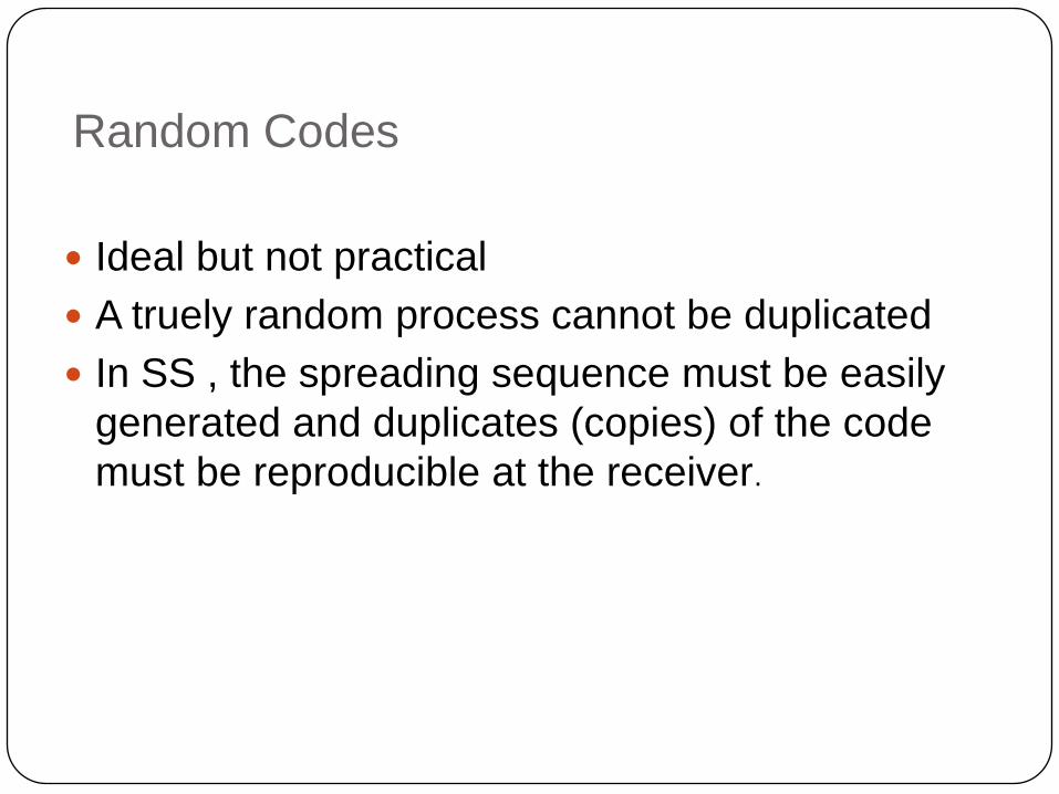
Random Codes
Ideal but not practical
A truely random process cannot be duplicated
In SS , the spreading sequence must be easily
generated and duplicates (copies) of the code
must be reproducible at the receiver.

Pseudo -Noise (PN) Sequences
PN Sequences are periodic, deterministic and binary
sequences with a noise like wave form
Known as Pseudo -random since it looks randomly for the
user who does not know the code
The longer the period of PN spreading code, the harder to
be detected sequence
The sequence can be generated using feedback shift
registers which are made up of m flip flops -that have two
states memory stages and logic circuit .
There are many types of code (Gold, m-sequence, Walsh-
Hadamard, etc)

PN Codes are generated from prime polynomials using
modulo-2 arithmetic.
Consists of shift registers & XOR gates.
The length (period)of the PN Code is equal to 2m -1 ( m=
no. of shift registers).

Some Terminology Related To The Pseudo-random Code:
Chipping Frequency (fc): the bit rate of the PN code
Chipping interval : 814 nsec
Information rate (fi): the bit rate of the digital data.
Chip: One bit of the PN code.
Epoch: The length of time before the code starts
repeating itself (the period of the code).
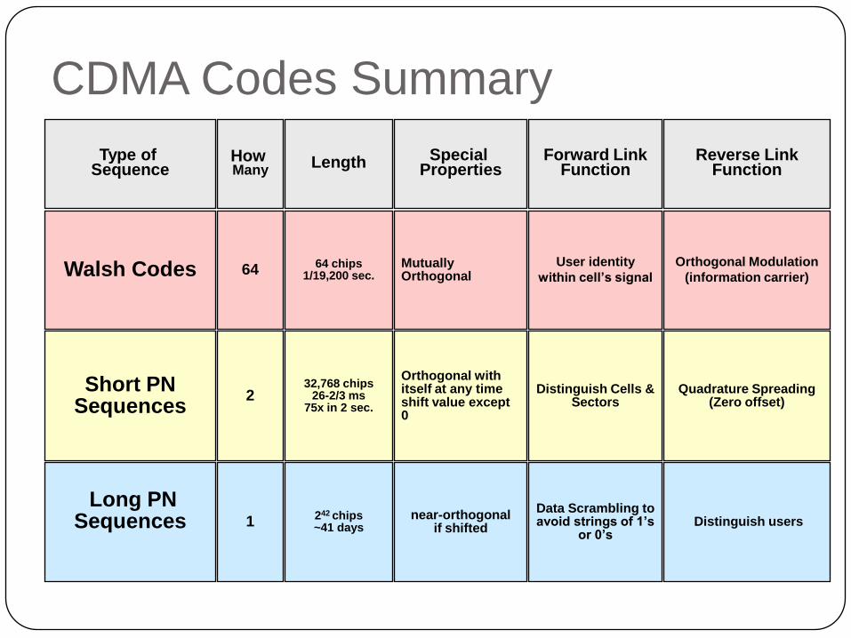
CDMA Codes Summary
Walsh Codes
Short PN Sequences
Long PNSequences
Type of Sequence
Mutually Orthogonal
Orthogonal with itself at any time shift value except 0
near-orthogonal if shifted
Special Properties
64
2
1
How Many
64 chips1/19,200 sec.
32,768 chips26-2/3 ms
75x in 2 sec.
242 chips~41 days
Length
Orthogonal Modulation
(information carrier)
Quadrature Spreading (Zero offset)
Distinguish users
Reverse Link Function
User identity
within cell’s signal
Distinguish Cells & Sectors
Data Scrambling to avoid strings of 1’s
or 0’s
Forward Link Function

Generation 1G 2G 2G 3G 3G 4G
NAME OF STADARD NMT GSM
IS-95 (CDMA
one)
UMTS (3GSM)
IS-2000
(CDMA 2000)
LTE
Year of First Use 1981 1991 1995 2001 2000 / 2002 2009
Technology( Multiple access
technique)FDMA TDMA & FDMA CDMA W-CDMA CDMA OFDMA
Encoding Analog Digital Digital Digital Digital Digital
Handset interoperability None SIM card None SIM card RUIM SIM card
Handoff Hard Hard Soft Soft Soft Soft
Voice and Data at the same
timeNo Yes GPRS No Yes No EVDO /
Yes SVDO
No (data only)Voice
possible though

Common
NameFamily Primary Use Radio Tech
Down
stream
(Mbps)
Up
stream
(Mbps)
Notes
EDGE
EvolutionGSM Mobile Internet TDMA/FDD 1.6 0.5 3GPP Release 7
EV-DO CDMA2000 Mobile Internet CDMA/FDD
2.45
3.1
4.9xN
0.15
1.8
1.8xN
Rev B note: N is
the number of
1.25 MHz carriers
used. EV-DO is not
designed for voice,
and requires a
fallback to 1xRTT
when a voice call
is placed or
received.
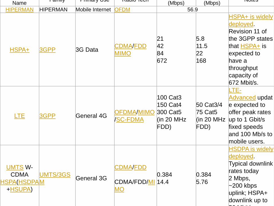
NameFamily Primary Use Radio Tech
(Mbps) (Mbps)Notes
HIPERMAN HIPERMAN Mobile Internet OFDM 56.9
HSPA+ 3GPP 3G DataCDMA/FDD
MIMO
21
42
84
672
5.8
11.5
22
168
HSPA+ is widely
deployed.
Revision 11 of
the 3GPP states
that HSPA+ is
expected to
have a
throughput
capacity of
672 Mbit/s.
LTE 3GPP General 4GOFDMA/MIMO
/SC-FDMA
100 Cat3
150 Cat4
300 Cat5
(in 20 MHz
FDD)
50 Cat3/4
75 Cat5
(in 20 MHz
FDD)
LTE-
Advanced updat
e expected to
offer peak rates
up to 1 Gbit/s
fixed speeds
and 100 Mb/s to
mobile users.
UMTS W-
CDMA
HSPA(HSDPA
+HSUPA)
UMTS/3GS
MGeneral 3G
CDMA/FDD
CDMA/FDD/MI
MO
0.384
14.4
0.384
5.76
HSDPA is widely
deployed.
Typical downlink
rates today
2 Mbps,
~200 kbps
uplink; HSPA+
downlink up to
56 Mbit/s.

LTE 3GPP General 4GOFDMA/MIMO/SC
-FDMA
100 Cat3
150 Cat4
300 Cat5
(in 20 MHz
FDD)[
50 Cat3/4
75 Cat5
(in 20 MHz
FDD)
LTE-
Advanced update
expected to offer
peak rates up to
1 Gbit/s fixed speeds
and 100 Mb/s to
mobile users.
UMTS W-
CDMA
HSPA(HSDPA+
HSUPA)
UMTS/3GSM General 3G
CDMA/FDD
CDMA/FDD/MIMO
0.384
14.4
0.384
5.76
HSDPA is widely
deployed. Typical
downlink rates today
2 Mbit/s, ~200 kbit/s
uplink; HSPA+
downlink up to
56 Mbit/s.
UMTS-TDD UMTS/3GSMMobile
InternetCDMA/TDD 16
Reported speeds
according
toIPWireless using
16QAM modulation
similar
toHSDPA+HSUPA

Wi-Fi802.11
(11n)Mobile Internet OFDM/MIMO
288.8 (using 4x4 configuration in
20 MHz bandwidth) or 600 (using 4x4
configuration in 40 MHz bandwidth)
Antenna, RF
front
endenhanceme
nts and minor
protocol timer
tweaks have
helped deploy
long
range P2Pnetw
orks
compromising
on radial
coverage,
throughput
and/or spectra
efficiency
(310 km & 382 k
m)
WiMax rel 1 802.16 Wireless MANMIMO-
SOFDMA37 (10 MHz TDD)
17 (10 MHz
TDD)With 2x2 MIMO
WiMax rel 1.5802.16-
2009Wireless MAN
MIMO-
SOFDMA
83 (20 MHz TDD)
141 (2x20 MHz FDD)
46 (20 MHz
TDD)
138 (2x20 MHz
FDD)
With 2x2
MIMO.Enhance
d with 20 MHz
channels in
802.16-2009
WiMAX rel 2 802.16m WirelessMANMIMO-
SOFDMA
2x2 MIMO
110 (20 MHz TDD)
183 (2x20 MHz FDD)
4x4 MIMO
2x2 MIMO
70 (20 MHz
TDD)
188 (2x20 MHz
FDD)
4x4 MIMO
Also, low
mobility users
can aggregate
multiple
channels to get

Three Core concept Of cellular system
There are three core concept which works behind
cellular system
Cell( which tessellate overall coverage area)
Frequency reuse
Handoff

Instead of one cell(covering area) with one
high power transmitter ,the entire city or
covering area is broken up into smaller
area which is called cell.

City is divided in hexagonal cell
Cell

Each of these smaller coverage areas has its
own low power base station.
User phones in one cell communicate with the
base station in that cell.


Why Hexagon Cell ? Ideally base stations have identical, circular
coverage areas
Circles may be good option but circles Don’t
Tessellate
The most circular of the regular polygons that
tessellate is the hexagon.
Thus, early researchers started using hexagons
to represent the coverage area of a base station
which is called cell.
What is Cell ?
A cell is the basic geographical unit of a
cellular System
Defined as the area where radio coverage is
given by one base station.

Types of Cells
On the basis of coverage area, cells may be
classified as
Macro cell
Micro cell
Pico cell
Femto cell

Macro cell
radius (1-35)Km
used in rural areas or along highways
provide coverage to larger area .
The antennae for macro cells are mounted on
ground-based masts, rooftops etc
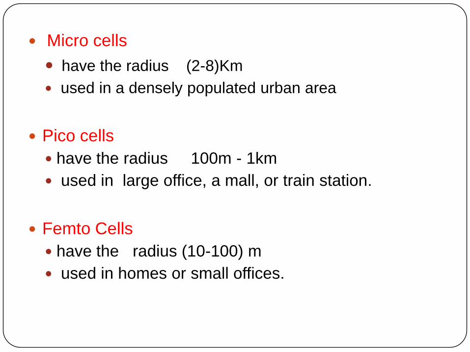
Micro cells
have the radius (2-8)Km
used in a densely populated urban area
Pico cells
have the radius 100m - 1km
used in large office, a mall, or train station.
Femto Cells
have the radius (10-100) m
used in homes or small offices.


Frequency Reuse
Though the first mobile system achieve its goal
for large coverage area but it was no option to
reuse the frequency.
In proportion of mobile users demand,
government regulatory authority could not
allocate spectrum
So there was a strong need to restructure the
mobile system to achieve capacity with coverage.

Need Of frequency Reuse
Frequency spectrum is a scarce
GSM is not used for voice communication, but it is also used for
data communications .
e.g 900MHz band have 25 MHz frequency band which account to
a maximum of 125 frequency channels
Within an eightfold time multiplex for each carrier ,a maximum of
1000 channels can be accommodated .
This number is further reduced by guard bands and the overhead
required for signaling .

Frequency reuse -
To serve several millions of subscribers
,frequencies must be spatially reused .
This concept led to the development of cellular
technology ,
This allowed a significant improvement in the
economic use of frequencies for capacity and
coverage.

an intelligent Frequency allocation Planning
The solution ,the industry adopted is called frequency planning or frequency Reuse.
Each BTS is allocated a group of radio channels to be used within a cell.
The same group of channels may be use in other cell in particular cell which is called frequency reuse.
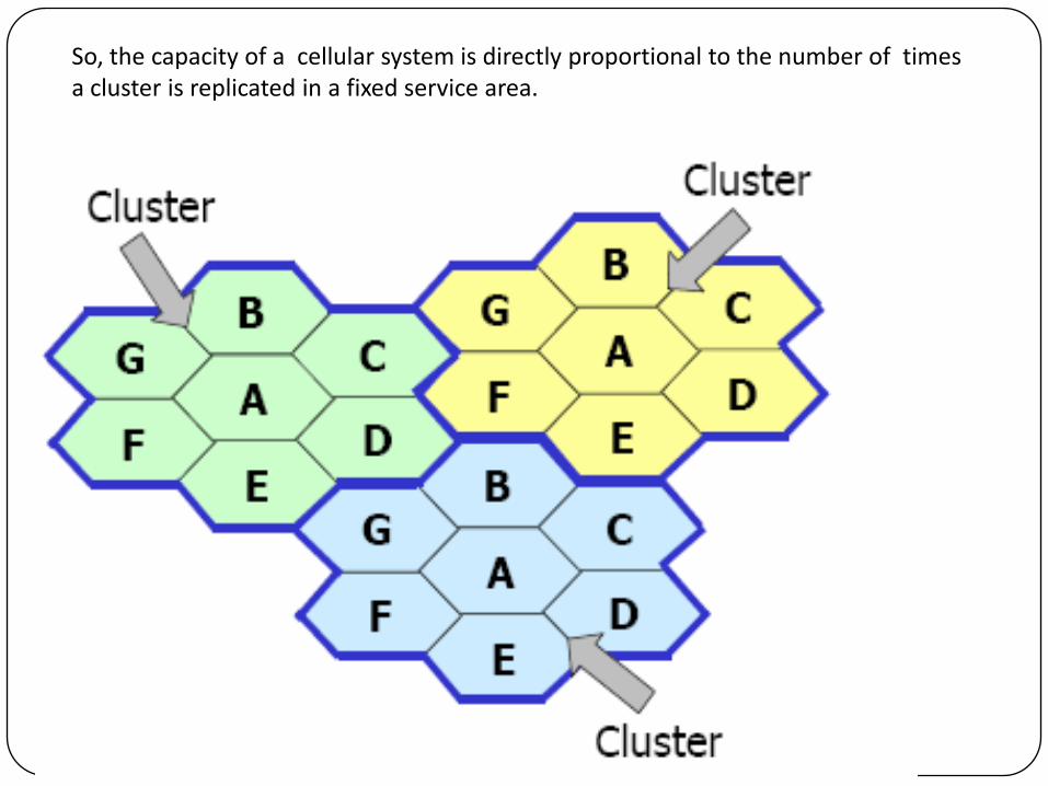
So, the capacity of a cellular system is directly proportional to the number of times a cluster is replicated in a fixed service area.

It is decided by Frequency reuse Distance(D) ?
The distance between two centre of co-
channel cell is called frequency reuse distance
(D)

The frequency reuse distance (D) is given by
D= R
where N=i²+ij+j²
R= Radius of the cell
N=No. of cells in a cluster

The cells which use the same set of frequency are called co-channel cell
Co-channel cell
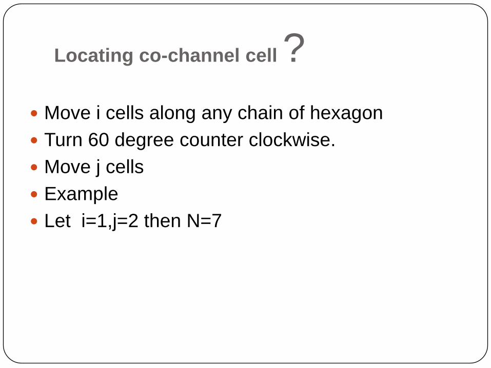
Locating co-channel cell ?
Move i cells along any chain of hexagon
Turn 60 degree counter clockwise.
Move j cells
Example
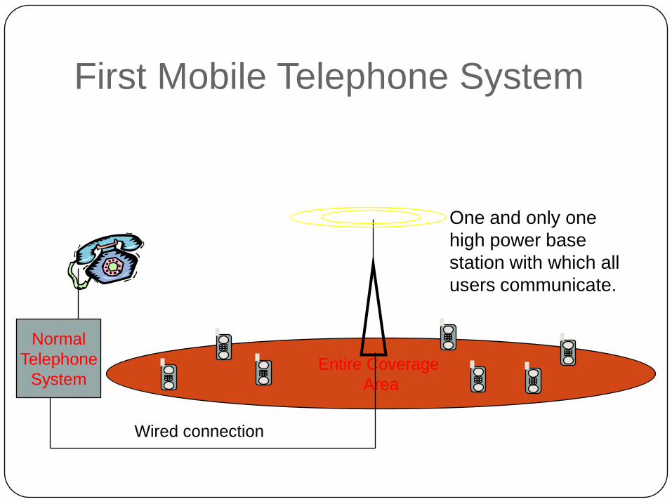
Let i=1,j=2 then N=7
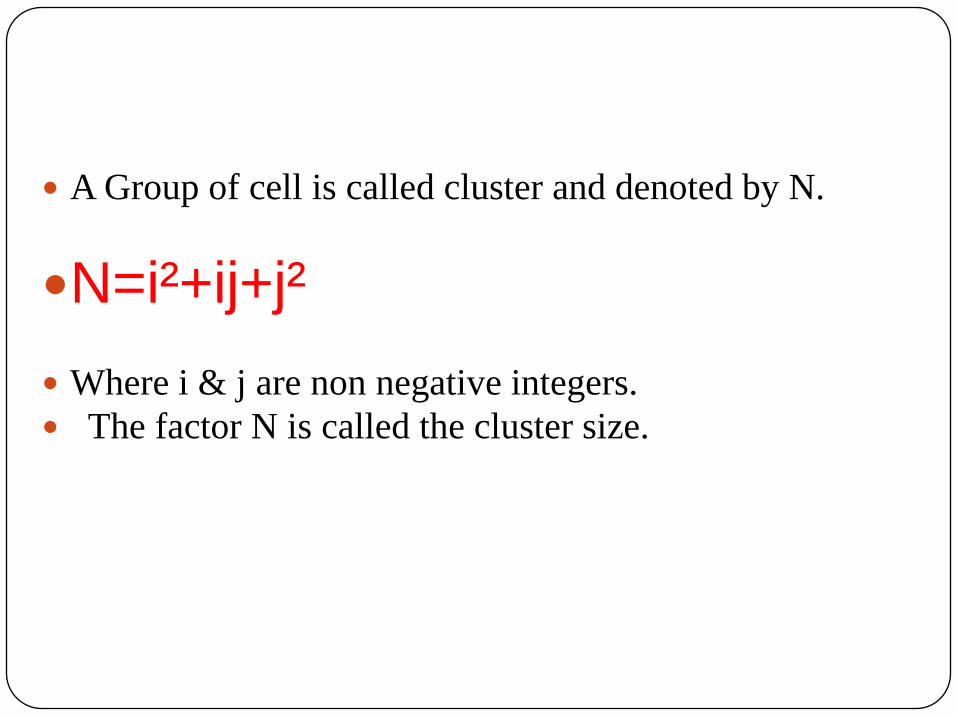
A Group of cell is called cluster and denoted by N.
N=i²+ij+j²
Where i & j are non negative integers.
The factor N is called the cluster size.
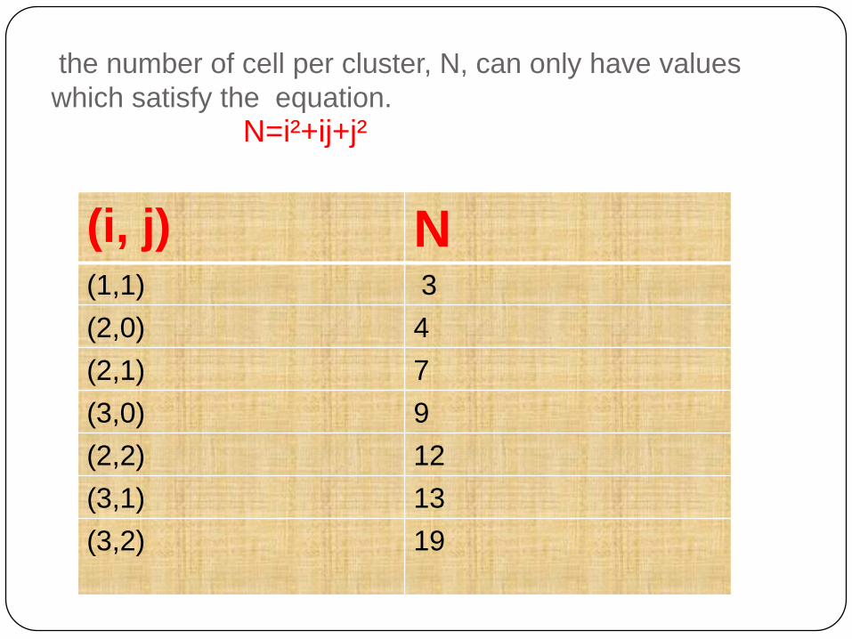
the number of cell per cluster, N, can only have values
which satisfy the equation.
N=i²+ij+j²
(i, j) N(1,1) 3
(2,0) 4
(2,1) 7
(3,0) 9
(2,2) 12
(3,1) 13
(3,2) 19

Design Objectives for Cluster
formation
High spectrum efficiency
Required : many users per cell
Remedy : small cluster size gives much
bandwidth per cell
Drawback: More interference or low QoS
High performance
Required : Little interference
Remedy : Large cluster sizes
Drawback :less users per cell

All the best…