Embed Size (px)
Citation preview

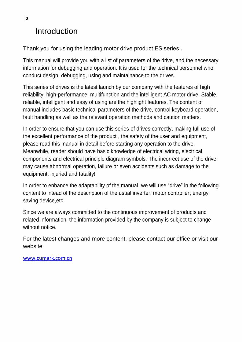
Firmware Manual(Standard Control Procedure) ES580/850 Series(0.37 to 630 kW) ES350 Series(0.37 to 4.0 kW) Other series in accordance with the machine model.
2
Introduction
Thank you for using the leading motor drive product ES series . This manual will provide you with a list of parameters of the drive, and the necessary
information for debugging and operation. It is used for the technical personnel who
conduct design, debugging, using and maintainance to the drives.
This series of drives is the latest launch by our company with the features of high
reliability, high-performance, multifunction and the intelligent AC motor drive. Stable,
reliable, intelligent and easy of using are the highlight features. The content of
manual includes basic technical parameters of the drive, control keyboard operation,
fault handling as well as the relevant operation methods and caution matters.
In order to ensure that you can use this series of drives correctly, making full use of
the excellent performance of the product , the safety of the user and equipment,
please read this manual in detail before starting any operation to the drive.
Meanwhile, reader should have basic knowledge of electrical wiring, electrical
components and electrical principle diagram symbols. The incorrect use of the drive
may cause abnormal operation, failure or even accidents such as damage to the
equipment, injuried and fatality!
In order to enhance the adaptability of the manual, we will use “drive” in the following
content to intead of the description of the usual inverter, motor controller, energy
saving device,etc.
Since we are always committed to the continuous improvement of products and
related information, the information provided by the company is subject to change
without notice.
For the latest changes and more content, please contact our office or visit our
website
www.cumark.com.cn

3
Firmware Manual(Applicable to standard control procedures)
1. Manual Introduction
Content
Describes the contents of the manual, as well as introduces the information about
applicability, safety and target readers.
Applicability
This manual is applicable to standard control procedures.
Safety Introduction
Please comply with all safety instructions submitted by the drive.
• Please read the complete safety instructions before installing, debugging or using the
drive. The complete safety information is given in the front of the drive【Hardware
manual】.
• Please read the warnings and precautions of this software before modifying the default
value for a function. For each function, this manual is given in the introduction of user
adjustable parameters should pay attention to the warnings and precautions.
Target Readers
Readers of this manual should have the basic knowledge of standard electrical wiring,
electronic components and electrical schematic symbols.
Main Contents Introduction
This manual contains the following chapters:
•Control Keyboard provides a description of the control keyboard and instructions for use.
• Program Function introduces the basic functions and characteristics of the drive and the main implementation methods.
• Driver Parameter List describes the parameters of the drive.
• Field Bus introduces the main communication characteristics and mechanism of the drive and other relative settings.
• Fault Tracking and Processing lists alarm (warning) and fault information as well as possible causes and solutions.
©2017 Shenzhen Cumark New Technology Co,ltd.Copyright

4
Catalogue 1. Manual Introduction ........................................................................... 3
Content .................................................................................................... 3
2.LCD Control Keyboard ....................................................................... 7 Operation Instructions ···································································· 10
Basic Operation ··············································································· 10
Task Iist ···························································································· 11
Terms in English and Chinese ························································ 12
Arbitrary Pattern ·············································································· 13
Main Interface Mode ········································································ 13
Main Menu Mode ·············································································· 15
Parameters List ........................................................................................... 15 Modified parameters ................................................................................. 20 Fault logs .................................................................................................... 20 Assistants ................................................................................................... 22 Parameters backup .................................................................................... 22 SYSTEM INFO .............................................................................................. 24 Settings ....................................................................................................... 26
Option Menu Mode ·········································································· 27
Local Given ................................................................................................. 27 Motor Rotation Direction ........................................................................... 27 Edit Main Interface .................................................................................... 27
3. LED Control Keyboard ..................................................................... 28 Operation Instructions ···································································· 28
4.Program Function ............................................................................. 30 Control Place ··················································································· 30
Local Control .............................................................................................. 30 Remote Control .......................................................................................... 30
Start Stop Control ············································································ 30
Start Stop Logic .......................................................................................... 30 Jog Start ...................................................................................................... 31 Emergency Shutdown ................................................................................ 31 Fault Shutdown .......................................................................................... 31
External Control Place ···································································· 31
Terminal Two-wire, Three-wire Control ..................................................... 32 Speed/Torque Control ................................................................................ 32
Speed Given ····················································································· 33
Analog Input Speed Given .......................................................................... 33 High-Speed Pulse Input Speed Given ......................................................... 33 Communication Speed Given ..................................................................... 33 Multi Speed ................................................................................................ 35 Electric Potentiometer(also named as terminal acceleration and deceleration function) ................................................................................ 36 Speed Given Ramp Generator .................................................................... 36
Control Interface ·············································································· 38
Digital Input Logic(DI1~DI7) .................................................................. 38 Digital Output Logic (DO1, DO2, RO1, RO2) ............................................... 38 Analog Input (AI1, AI2, AI3) ........................................................................ 39 High Speed Pulse Input (DI7) ...................................................................... 39 Analog Output(AO1,AO2) ........................................................................... 39 High Speed Pulse Output(DO2) .................................................................. 40
Process PID Control ········································································ 41
Motor Thermal Protection ......................................................................... 42
System Control ················································································ 43
Lifting Function ··············································································· 44
Editable Logic Function ·································································· 44

5
Level Timer ................................................................................................. 44 Along Counter ............................................................................................ 45 Comparator ................................................................................................ 45 Logic Arithmetic Unit .................................................................................. 45
Programmable Arithmetic Function ··············································· 46
Process Variable Conversion ...................................................................... 46 Basic Arithmetic Operation ........................................................................ 46 Universal Filter ........................................................................................... 47 Integrator ................................................................................................... 47
Fault Warning Programming··························································· 47
Typical Industry Application Solutions ········································· 48
5. Drive Parameters list ........................................................................ 49 01 Actual values ·············································································· 49
02 I/O Values ···················································································· 51
03 Control Values ············································································ 52
04 App values ·················································································· 53
05 Timer & counter ·········································································· 54
06 Drive Status ················································································· 56
08 Fault&Alarm Log ········································································· 62
09 System Info ················································································· 62
10 Start/Stop/Dir ·············································································· 63
11 Start/Stop Mode ·········································································· 66
13 Analog & pulse in(Analog Quantity and Pulse Input) ·············· 67
14 Digital I/O(Digital input and output) ·········································· 70
15 Analog & pulse out ····································································· 75
16 System ························································································· 79
17 Data logger ·················································································· 82
18 Fault log ······················································································· 84
19 Speed Calculation ······································································· 85
20 Limits ··························································································· 86
21 Speed Reference ········································································· 87
22 Speed Ramp(Speed Given Ramp Generator) ··························· 89
23 Speed Control ············································································· 91
24 Torque Reference ······································································· 91
25 Critical Speed ·············································································· 93
26 Constant Speeds ········································································ 94
27 Process PID ················································································· 97
29 Timer Function ············································································ 101
30 Fault function ·············································································· 103
31 Motor Therm Prot ········································································ 105
32 Factory Setting ··········································································· 107
33 Signal Generator ········································································· 109
34 Logic Function ············································································ 110
35 Math function ············································································· 115
40 Pos control ·················································································· 119
42 Mech brake ·················································································· 121
43 Winder ························································································· 123
47 Multi step ctrl ·············································································· 125
48Switch Sync ················································································· 128
49 Data storage ················································································ 129
50 Fieldbus ······················································································ 130
51 Embedded Modbus ····································································· 131
6
52 CANopen ····················································································· 134
60 Motor control ·············································································· 137
61 Encoder config ··········································································· 139
62 Motor parameter ········································································· 140
63 Startup parameter ······································································· 141
6. Field Bus ......................................................................................... 144 data set ····························································································· 144
Modbus ····························································································· 147
Parameter address ................................................................................... 148
CANopen ·························································································· 150
CANopen Protocol introduction ............................................................. 150 Communication object ............................................................................. 150 Download SDO ......................................................................................... 151 Upload SDO .............................................................................................. 153 SDO Abort transmission ........................................................................... 154 Emergency message ................................................................................. 155 Object dictionary ...................................................................................... 155 Communication profile parameters DS 301 ............................................. 156 Drive and motion control device profile parameters of DSP 402 ............ 158 Manufacturer specific parameters ........................................................... 160 Drive control ............................................................................................. 160
7. Fault tracking and processing ...................................................... 163 How to reset ····················································································· 163
Fault code and interpretation ·························································· 163
8.More information ............................................................................. 166 Product and service consulting ····················································· 166
Provide feedback about this manual ············································· 166
7
control keyboard
2.LCD Control Keyboard
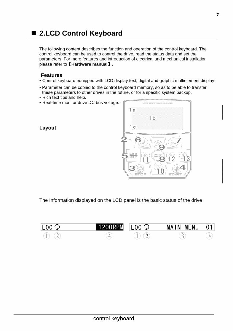
The following content describes the function and operation of the control keyboard. The control keyboard can be used to control the drive, read the status data and set the parameters. For more features and introduction of electrical and mechanical installation
please refer to【Hardware manual】.
Features • Control keyboard equipped with LCD display text, digital and graphic multielement display.
• Parameter can be copied to the control keyboard memory, so as to be able to transfer these parameters to other drives in the future, or for a specific system backup.
• Rich text tips and help.
• Real-time monitor drive DC bus voltage.
Layout
The Information displayed on the LCD panel is the basic status of the drive
2
3 4
5
7
8
9
10
11 12
6
13
1a
1b
1c
LOC
1 2 4LOC MAIN MENU 01
1 2 3 4
8
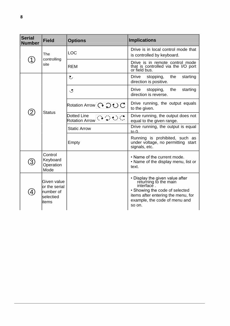
Serial Number
Field Options Implications
○1
The
controlling
site
LOC Drive is in local control mode that
is controlled by keyboard.
REM Drive is in remote control mode that is controlled via the I/O port or field bus.
○2 Status
Drive stopping, the starting
direction is positive.
Drive stopping, the starting
direction is reverse.
Rotation Arrow Drive running, the output equals
to the given.
Dotted Line Rotation Arrow
Drive running, the output does not
equal to the given range.
Static Arrow Drive running, the output is equal
to 0.
Empty Running is prohibited, such as under voltage, no permitting start signals, etc.
○3
Control
Keyboard
Operation
Mode
• Name of the current mode. • Name of the display menu, list or text.
○4
Given value
or the serial
number of
selectied
items
• Display the given value after returning to the main interface .
• Showing the code of selected items after entering the menu, for example, the code of menu and so on.
--------------- Firmware manual(Standard control procedure)--------------- 9
Control Keyboard
Serial Number
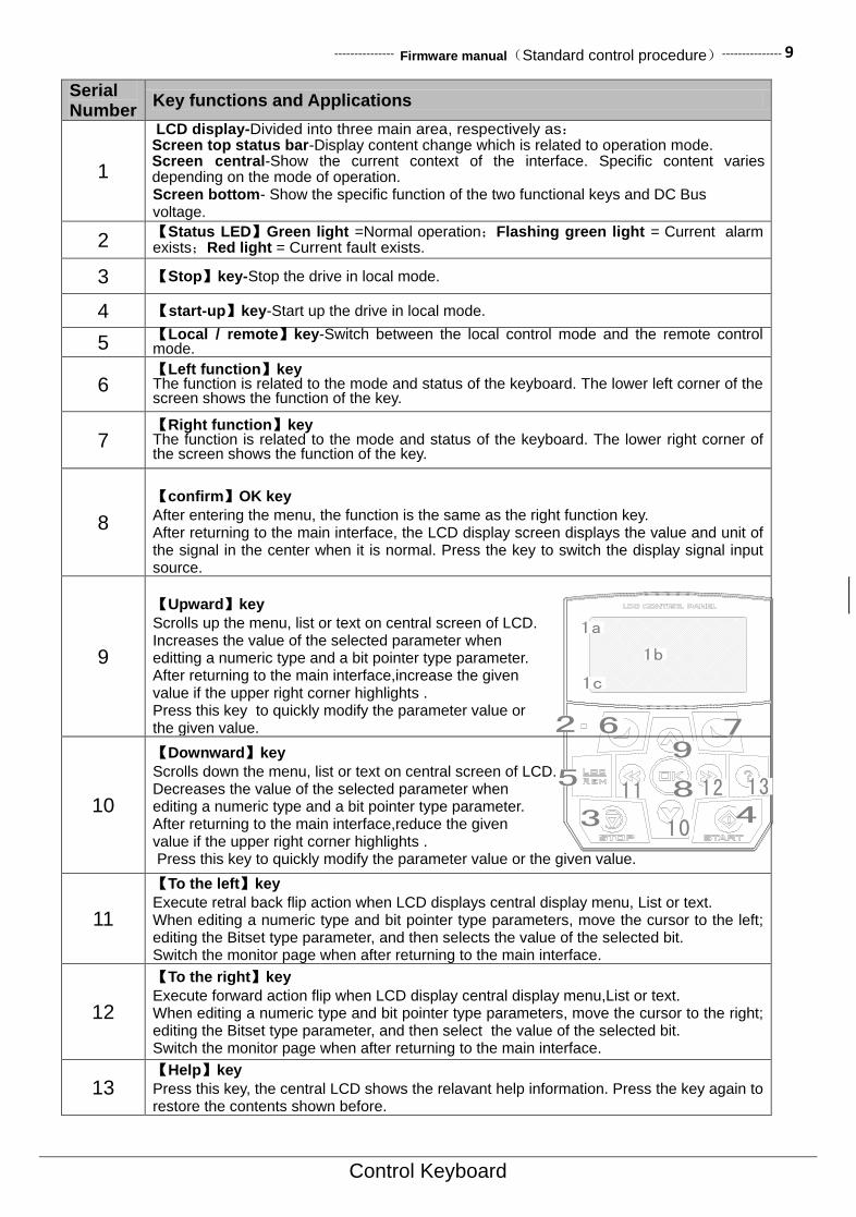
Key functions and Applications
1
LCD display-Divided into three main area, respectively as: Screen top status bar-Display content change which is related to operation mode. Screen central-Show the current context of the interface. Specific content varies depending on the mode of operation. Screen bottom- Show the specific function of the two functional keys and DC Bus voltage.
2 【Status LED】Green light =Normal operation;Flashing green light = Current alarm exists;Red light = Current fault exists.
3 【Stop】key-Stop the drive in local mode.
4 【start-up】key-Start up the drive in local mode.
5 【Local / remote】key-Switch between the local control mode and the remote control mode.
6 【Left function】key The function is related to the mode and status of the keyboard. The lower left corner of the screen shows the function of the key.
7 【Right function】key The function is related to the mode and status of the keyboard. The lower right corner of the screen shows the function of the key.
8
【confirm】OK key
After entering the menu, the function is the same as the right function key. After returning to the main interface, the LCD display screen displays the value and unit of the signal in the center when it is normal. Press the key to switch the display signal input source.
9
【Upward】key
Scrolls up the menu, list or text on central screen of LCD. Increases the value of the selected parameter when editting a numeric type and a bit pointer type parameter. After returning to the main interface,increase the given value if the upper right corner highlights . Press this key to quickly modify the parameter value or the given value.
10
【Downward】key
Scrolls down the menu, list or text on central screen of LCD. Decreases the value of the selected parameter when editing a numeric type and a bit pointer type parameter. After returning to the main interface,reduce the given value if the upper right corner highlights . Press this key to quickly modify the parameter value or the given value.
11
【To the left】key
Execute retral back flip action when LCD displays central display menu, List or text. When editing a numeric type and bit pointer type parameters, move the cursor to the left; editing the Bitset type parameter, and then selects the value of the selected bit. Switch the monitor page when after returning to the main interface.
12
【To the right】key
Execute forward action flip when LCD display central display menu,List or text. When editing a numeric type and bit pointer type parameters, move the cursor to the right; editing the Bitset type parameter, and then select the value of the selected bit. Switch the monitor page when after returning to the main interface.
13 【Help】key
Press this key, the central LCD shows the relavant help information. Press the key again to restore the contents shown before.
2
3 4
5
7
8
9
10
11 12
6
13
1a
1b
1c
10--------------- Firmware manual(Standard control procedure)---------------
control keyboard
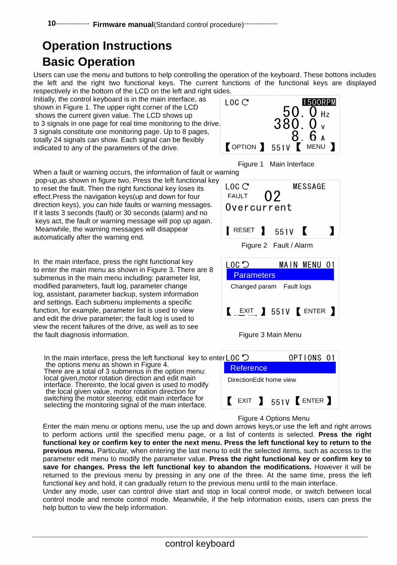
Operation Instructions
Basic Operation Users can use the menu and buttons to help controlling the operation of the keyboard. These bottons includes the left and the right two functional keys. The current functions of the functional keys are displayed respectively in the bottom of the LCD on the left and right sides. Initially, the control keyboard is in the main interface, as shown in Figure 1. The upper right corner of the LCD shows the current given value. The LCD shows up to 3 signals in one page for real time monitoring to the drive. 3 signals constitute one monitoring page. Up to 8 pages, totally 24 signals can show. Each signal can be flexibly indicated to any of the parameters of the drive.
Figure 1 Main Interface When a fault or warning occurs, the information of fault or warning pop-up,as shown in figure two, Press the left functional key to reset the fault. Then the right functional key loses its effect.Press the navigation keys(up and down for four direction keys), you can hide faults or warning messages. If it lasts 3 seconds (fault) or 30 seconds (alarm) and no keys act, the fault or warning message will pop up again. Meanwhile, the warning messages will disappear automatically after the warning end.
Figure 2 Fault / Alarm In the main interface, press the right functional key to enter the main menu as shown in Figure 3. There are 8 submenus in the main menu including: parameter list, modified parameters, fault log, parameter change log, assistant, parameter backup, system information and settings. Each submenu implements a specific function, for example, parameter list is used to view and edit the drive parameter; the fault log is used to view the recent failures of the drive, as well as to see the fault diagnosis information. Figure 3 Main Menu
In the main interface, press the left functional key to enter the options menu as shown in Figure 4. There are a total of 3 submenus in the option menu: local given,motor rotation direction and edit main interface. Thereinto, the local given is used to modify the local given value, motor rotation direction for switching the motor steering; edit main interface for selecting the monitoring signal of the main interface.
Figure 4 Options Menu Enter the main menu or options menu, use the up and down arrows keys,or use the left and right arrows to perform actions until the specified menu page, or a list of contents is selected. Press the right functional key or confirm key to enter the next menu. Press the left functional key to return to the previous menu. Particular, when entering the last menu to edit the selected items, such as access to the parameter edit menu to modify the parameter value. Press the right functional key or confirm key to save for changes. Press the left functional key to abandon the modifications. However it will be returned to the previous menu by pressing in any one of the three. At the same time, press the left functional key and hold, it can gradually return to the previous menu until to the main interface. Under any mode, user can control drive start and stop in local control mode, or switch between local control mode and remote control mode. Meanwhile, if the help information exists, users can press the help button to view the help information.
LOC
【选项】 【菜单】551V
50.0 Hz
380.0 v
8.6 A
LOC
【复位】 【 】551V
故障 02Overcurrent
MESSAGE
LOC MAIN MENU 01
【退出】 【进入】551V
修改过的参数故障日志
LOC OPTIONS 01
【退出】 【进入】551V
电机旋转方向编辑主界面
OPTION MENU
FAULT
RESET
Parameters
Changed param Fault logs
DirectionEdit home view
Reference
EXIT ENTER
ENTER
EXIT

--------------- Firmware manual(Standard control procedure)--------------- 11
control keyboard
Task Iist
Basic operation task Page number
How to acquire for help 12
How to control drive start & stop and switch local & remote control mode 12
How to modify speed,frequency or torque given value 12
How to switch monitoring signal and view input source of monitoring signal 13
How to select a monitoring signal and view or edit its input source 25
How to adjust backlight brightness and contrast ratio of LCD display 14
How to select a parameter and view its value 15
How to modify values of numeric type parameters 15
How to modify the value of an enumerated type parameters 16
How to view or modify the value of the bit type parameters 16
How to modify the value of the numeric pointer type parameters 17
How to modify the value of a bit pointer type parameter 17
How to view and edit modified parameters 18
How to view drive fault logs and fault diagnosis information 19
How to view and edit recently modified parameters
How to use an assistant to select an application macro 21
How to use the assistant to set motor parameters 21
How to use the assistant to set the drive start stop control parameters 21
How to upload parameters to local (parameter copy) 21
How to transfer parameters to drive (parameter download) 22
How to view drive manufacturer, model, firmware version, production date and serial number info
23
How to view control keyboard firmware version and diagnostic information 23
How to clear drive fault logs 24
How to restore default monitoring signal on main interface 24
How to initialize all parameters of the drive 24
12--------------- Firmware manual(Standard control procedure)---------------
control keyboard
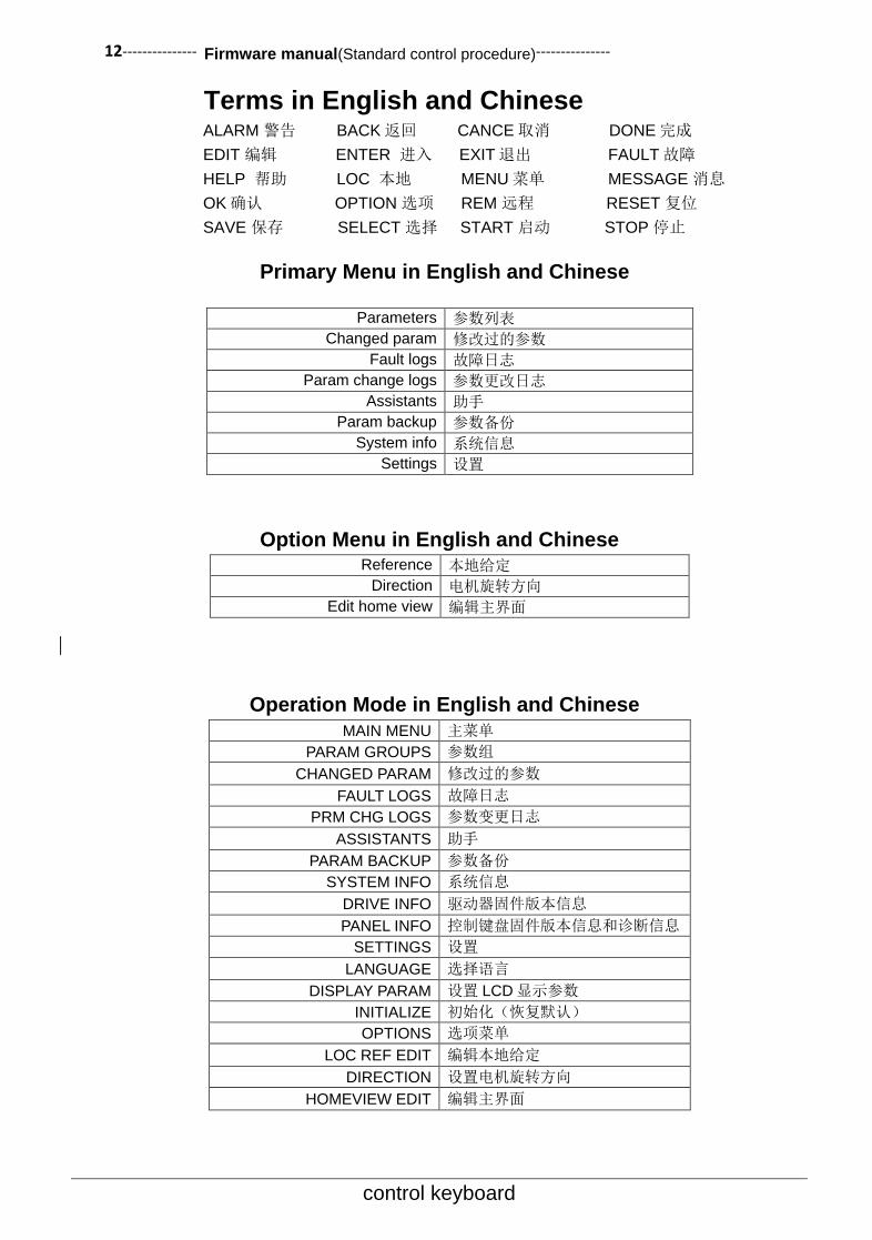
Terms in English and Chinese ALARM 警告 BACK 返回 CANCE 取消 DONE 完成
EDIT 编辑 ENTER 进入 EXIT 退出 FAULT 故障
HELP 帮助 LOC 本地 MENU 菜单 MESSAGE 消息
OK 确认 OPTION 选项 REM 远程 RESET 复位
SAVE 保存 SELECT 选择 START 启动 STOP 停止
Primary Menu in English and Chinese
Option Menu in English and Chinese Reference 本地给定
Direction 电机旋转方向
Edit home view 编辑主界面
Operation Mode in English and Chinese
MAIN MENU 主菜单
PARAM GROUPS 参数组
CHANGED PARAM 修改过的参数
FAULT LOGS 故障日志
PRM CHG LOGS 参数变更日志
ASSISTANTS 助手
PARAM BACKUP 参数备份
SYSTEM INFO 系统信息
DRIVE INFO 驱动器固件版本信息
PANEL INFO 控制键盘固件版本信息和诊断信息
SETTINGS 设置
LANGUAGE 选择语言
DISPLAY PARAM 设置 LCD 显示参数
INITIALIZE 初始化(恢复默认)
OPTIONS 选项菜单
LOC REF EDIT 编辑本地给定
DIRECTION 设置电机旋转方向
HOMEVIEW EDIT 编辑主界面
Parameters 参数列表
Changed param 修改过的参数
Fault logs 故障日志
Param change logs 参数更改日志
Assistants 助手
Param backup 参数备份
System info 系统信息
Settings 设置

--------------- Firmware manual(Standard control procedure)--------------- 13
control keyboard
Arbitrary Pattern How to acquire for help Step Action Display
1 If there is a help information, press the help key to pop up the help information.
2
If the help information content length exceeds the text length that LCD screen can display, you can press the navigation key (up and down or so four direction keys) for scrolling and turning the page, browse the remaining content.
3 After reading all the content, you can press the left functional key or press the help key again to exit this mode.
How to control drive start-stop and switch local / remote control mode Step Action Display
1
Switching between the remote control mode(Status bar on the left shows the words REM)and Local control mode (Status bar on the left show the words LOC), press the LOC/REM key. Note: this function is locked when the drive running. Using the parameters of 16.00Locallock(Local control locking)to disable the drive to enter the local control mode.
2
To stop the drive in the local control mode, press the STOP key. To start the drive in the local control mode, press the START key.
Main Interface Mode How to modify the speed, frequency or torque given value
Step Action Display
1 If it is not in the main interface, press the left functional key again till the return to the main interface.
2
If the given value is not in the highlighted
status, it indicates that the given value cannot
be modified. At this point, you can switch to the
local control mode or modify the given source
to keypad.
LOC
【退出】 【 】551V
Output display showsdrive status, refere-nce value and signals. Use Up/Down arrowkey to adjust refere-
HELP
LOC
【退出】 【 】551V
nce. Use Left/rightarrow key to switchbetween maxium 8 pag-es of signals.
HELP
LOC
【退出】 【 】551V
驱动器运行时不能切换控制模式
MESSAGE
LOC
【选项】 【菜单】551V
50.0 Hz
380.0 v
8.6 A
LOC
【选项】 【菜单】551V
50.0 Hz
380.0 v
8.6 A
1500RPM
EXIT
EXIT
EXIT
OPTION
N
OPTION
MENU
MENU
Drive cannot switch control
mode at run time.
14--------------- Firmware manual(Standard control procedure)---------------
control keyboard
Step Action Display
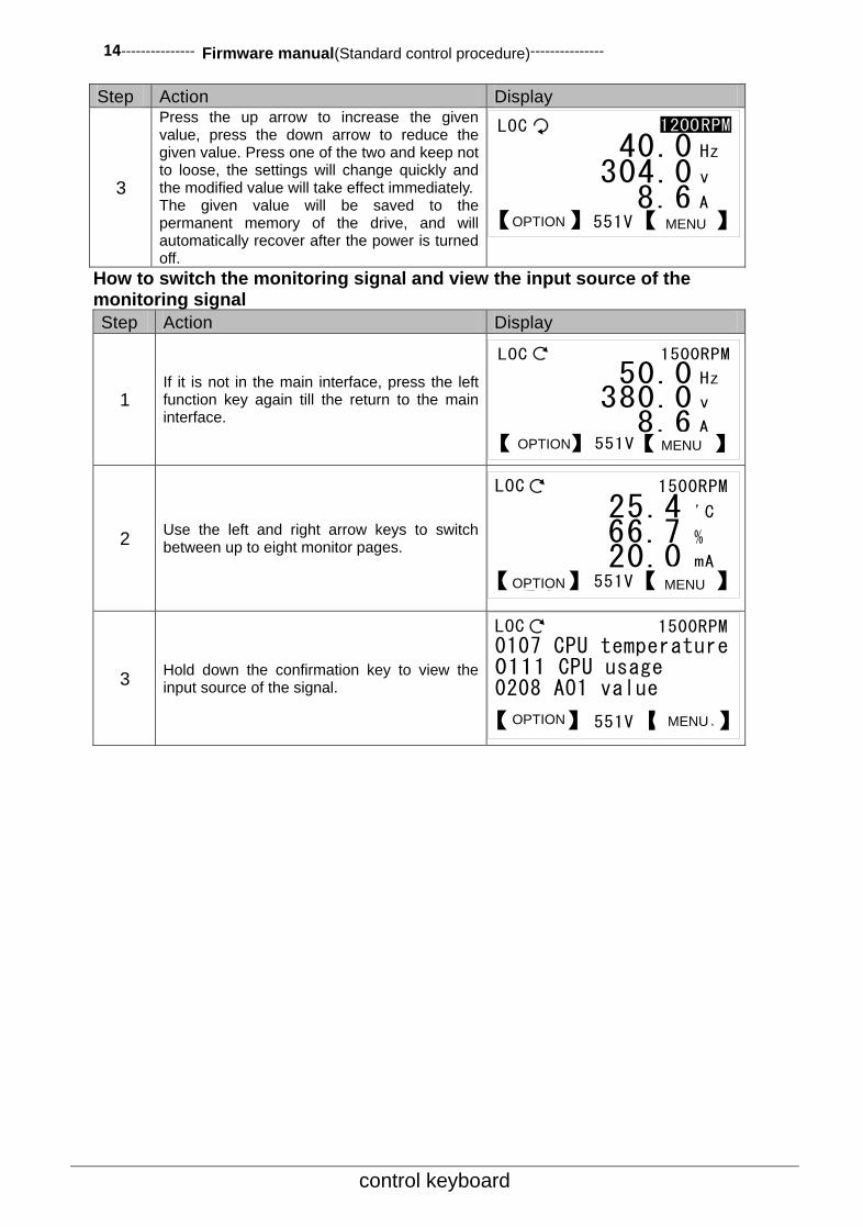
3
Press the up arrow to increase the given value, press the down arrow to reduce the given value. Press one of the two and keep not to loose, the settings will change quickly and the modified value will take effect immediately. The given value will be saved to the permanent memory of the drive, and will automatically recover after the power is turned off.
How to switch the monitoring signal and view the input source of the monitoring signal
Step Action Display
1 If it is not in the main interface, press the left function key again till the return to the main interface.
2 Use the left and right arrow keys to switch between up to eight monitor pages.
3 Hold down the confirmation key to view the input source of the signal.
LOC
【选项】 【菜单】551V
50.0 Hz
380.0 v
8.6 A
1500RPM
LOC
【选项】 【菜单】551V
40.0 Hz
304.0 v
8.6 A
LOC 1500RPM
【选项】 【菜单】551V
0107 CPU temperature0111 CPU usage0208 AO1 value
LOC 1500RPM
【选项】 【菜单】551V
25.4 'C
66.7 %
20.0 mA
OPTION MENU
OPTION MENU
OPTION
OPTION
MENU
MENU

--------------- Firmware manual(Standard control procedure)--------------- 15
control keyboard
How to adjust the backlight brightness and the contrast of LCD display Step Action Display
1 If it is not in the main interface, press the left function key again till the return to the main interface.
21
If it is not in the main interface, press the left function key again till the return to the main interface. Hold the right function key and press the up and down arrows to adjust the backlight brightness of the LCD display.
32
If it is not in the main interface, press the left function key again till the return to the main interface. Hold the left function key and press the up and down arrows to adjust the contrast ratio of the LCD display.
Main Menu Mode
Parameters List Parameter Type
English Chinese Define
INT16 16bit signed integer Maximum value range of [-32768, 32767] parameters
UINT16 16bit unsigned integer Maximum value range of [0, 65535] parameters
ENUM Enumeration A list of several options
PB A set of A collection of up to 16 Boolean variables
VAL POINTER
Value pointer A pointer to another parameter, which takes the value of another parameter as its own value
BIT POINTER
Bit pointer A pointer to a binary bit of another parameter, that is, takes the value of a binary bit of another parameter as its own value.
INT16,UINT16 and other types of parameters are collectively referred to as numeric type parameters. Parameter address forms as xx.yy Xx refers to the group number of the parameter, while yy refers to the index that the parameter within the group. For example, 01.00 represents the first parameter of the first group, 16.04 represents the fifth parameter of the sixteenth group. Take note that the index begins from 0.
Numeric pointer coding
b15 b8 b7 b0
Group number Indexes
For example, the value of the numeric pointer is equal to 256 (decimal) or 0100 (hexadecimal),
indicating that the pointer points to the first set of the first parameters.
LOC
【选项】 【菜单】551V
50.0 Hz
380.0 v
8.6 A
1500RPM
LOC 1500RPM
【选项】 【菜单】551V
背光亮度
LOC 1500RPM
【选项】 【菜单】551V
对比度
OPTION MENU
OPTION MENU
MENU OPTION
Contrast Ratio
BacklightBrightness
16--------------- Firmware manual(Standard control procedure)---------------
control keyboard
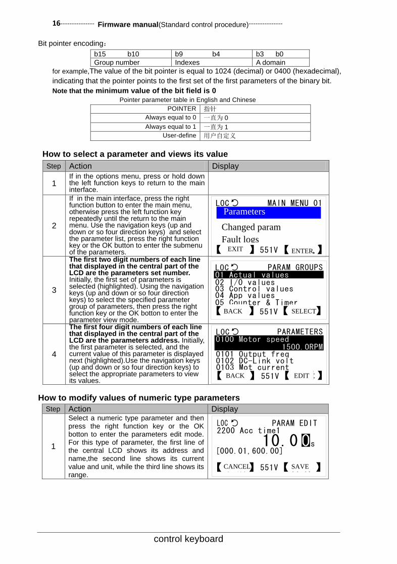
Bit pointer encoding:
b15 b10 b9 b4 b3 b0
Group number Indexes A domain
for example,The value of the bit pointer is equal to 1024 (decimal) or 0400 (hexadecimal),
indicating that the pointer points to the first set of the first parameters of the binary bit.
Note that the minimum value of the bit field is 0
Pointer parameter table in English and Chinese
POINTER 指针
Always equal to 0 一直为 0
Always equal to 1 一直为 1
User-define 用户自定义
How to select a parameter and views its value
Step Action Display
1 If in the options menu, press or hold down the left function keys to return to the main interface.
2
If in the main interface, press the right function button to enter the main menu, otherwise press the left function key repeatedly until the return to the main menu. Use the navigation keys (up and down or so four direction keys) and select the parameter list, press the right function key or the OK button to enter the submenu of the parameters.
3
The first two digit numbers of each line that displayed in the central part of the LCD are the parameters set number. Initially, the first set of parameters is selected (highlighted). Using the navigation keys (up and down or so four direction keys) to select the specified parameter group of parameters, then press the right function key or the OK botton to enter the parameter view mode.
4
The first four digit numbers of each line that displayed in the central part of the LCD are the parameters address. Initially, the first parameter is selected, and the current value of this parameter is displayed next (highlighted).Use the navigation keys (up and down or so four direction keys) to select the appropriate parameters to view its values.
How to modify values of numeric type parameters
Step Action Display
1
Select a numeric type parameter and then press the right function key or the OK botton to enter the parameters edit mode. For this type of parameter, the first line of the central LCD shows its address and name,the second line shows its current value and unit, while the third line shows its range.
LOC PARAM EDIT2200 Acc time1
[000.01,600.00]
【取消】 【保存】551V
s10.0
LOC PARAM GROUPS
【返回】 【选择】551V
02 I/O values03 Control values04 App values05 Counter & Timer
LOC PARAMETERS
【返回】 【编辑】551V
0101 Output freq0102 DC-Link volt0103 Mot current
LOC MAIN MENU 01
【退出】 【进入】551V
修改过的参数故障日志
Parameters
Changed param
Fault logs EXIT ENTER
BACK
CANCEL SAVE
BACK SELECT
EDIT

--------------- Firmware manual(Standard control procedure)--------------- 17
control keyboard
Step Action Display
2
Use the up and down arrow keys to modify the value of the selected parameter, while pressing the two keys can restore its default value. The initial cursor is located in the unit position of the parameter value (highlighted), press the left and right arrow keys to move the cursor. Press the up and down arrow keys, the parameter values change quickly.
3 To save the modification to make the new value valid, press the right function key or the OK bottton. To discard the modification and keep the original value, press the left function key.
How to modify the value of enumeration type parameters
Step Action Display
1
Select an enumeration type parameter and press the right function key or the OK botton to enter the parameter edit mode. For this type of parameters, LCD display lists a number of options in the center, the current options hightlighted. The number in front of each option is its value.
2
Use the up and dow direction keys to scroll the list of options, press the two buttons at the same time can restore the default options. Press the left and right arrow keys can perform flip action. Press the navigation key (up and down or so four direction key), the option list changes quickly.
3 To save the modification to make the new value valid, press the right function key or the OK bottton. To discard the modification and keep the original value, press the left function key.
How to view or modify the values of bit set type parameters
Step Action Display
1
Select a bit set type parameterand press the right function key or the OK botton to enter the parameter edit mode. For this type of parameter,the central LCD display lists a number of bit variables. The current value of each bit variable is displayed on the right side, the bit number of the currently selected bit variable is displayed in the upper right corner.
2
Use the left and right arrow keys to modify the value of the bit variable,while pressing these two keys can restore its default value.Initially, the first bit variable in the list of bit variables is selected (two solid triangles on the right),press the up and down direction keys to scroll the list
3 To save the modification to make the new value valid, press the right function key or the OK bottton. To discard the modification and keep the original value, press the left function key.
LOC PARAM EDIT2200 Acc time1
[000.01,600.00]
【取消】 【保存】551V
LOC PARAM EDIT1000 Ext1 start func
【取消】 【选择】551V
2, in1 FWD/in2 REV3, RUN/STOP/DIR
0, Not selected
LOC PARAM EDIT1000 Ext1 start func
【取消】 【选择】551V
1, in1 RUN/in2 DIR2, in1 FWD/in2 REV3, RUN/STOP/DIR
LOC BIT LIST 010600 Status word1
【返回】 【确定】551V
Ready to run 1Fault 0Alarm 0Limit active 0
LOC BIT LIST 160600 Status word1
【返回】 【确定】551V
Local ctrl 1Ready to run 0Fault 0Alarm 0
CANCEL SAVE
CANCEL SELECT
CANCEL SELECT
BACK OK
BACK OK
18--------------- Firmware manual(Standard control procedure)---------------
control keyboard
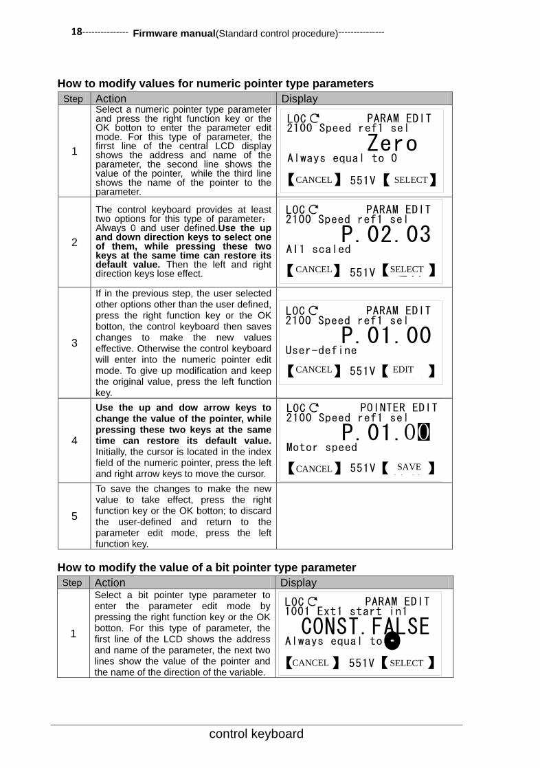
How to modify values for numeric pointer type parameters
Step Action Display
1
Select a numeric pointer type parameter and press the right function key or the OK botton to enter the parameter edit mode. For this type of parameter, the firrst line of the central LCD display shows the address and name of the parameter, the second line shows the value of the pointer, while the third line shows the name of the pointer to the parameter.
2
The control keyboard provides at least two options for this type of parameter:Always 0 and user defined.Use the up and down direction keys to select one of them, while pressing these two keys at the same time can restore its default value. Then the left and right direction keys lose effect.
3
If in the previous step, the user selected other options other than the user defined, press the right function key or the OK botton, the control keyboard then saves changes to make the new values effective. Otherwise the control keyboard will enter into the numeric pointer edit mode. To give up modification and keep the original value, press the left function key.
4
Use the up and dow arrow keys to change the value of the pointer, while pressing these two keys at the same time can restore its default value. Initially, the cursor is located in the index field of the numeric pointer, press the left and right arrow keys to move the cursor.
5
To save the changes to make the new value to take effect, press the right function key or the OK botton; to discard the user-defined and return to the parameter edit mode, press the left function key.
How to modify the value of a bit pointer type parameter
Step Action Display
1
Select a bit pointer type parameter to enter the parameter edit mode by pressing the right function key or the OK botton. For this type of parameter, the first line of the LCD shows the address and name of the parameter, the next two lines show the value of the pointer and the name of the direction of the variable.
LOC PARAM EDIT2100 Speed ref1 sel
【取消】 【编辑】551V
P.01.00User-define
LOC PARAM EDIT2100 Speed ref1 sel
【取消】 【选择】551V
P.02.03AI1 scaled
LOC PARAM EDIT1001 Ext1 start in1
【取消】 【选择】551V
CONST.FALSEAlways equal to 0
LOC PARAM EDIT2100 Speed ref1 sel
【取消】 【选择】551V
ZeroAlways equal to 0
LOC POINTER EDIT2100 Speed ref1 sel
【取消】 【保存】551V
P.01.Motor speed
0
CANCEL SELECT
CANCEL SELECT
CANCEL EDIT
CANCEL SAVE
CANCEL SELECT

--------------- Firmware manual(Standard control procedure)--------------- 19
control keyboard
Step Action Display
2
The control keyboard provides at least three options for this type of parameter:Has been 0,Has been 1 and user-defined. Use the up and down arrow keys to select one of them,while pressing these two keys at the same time can restore its default value,then the left and right direction keys out of action.
3
If in the previous step, user selected other options other than the user-defined, press the right function key or the OK botton , then the control keyboard saves the changes to make the new value effect; Otherwise, the control keyboard will enter into the bit pointer edit mode. To give up the modification and keep the original value, press the left function key.
4
Use the up and down arrow keys to modify the value of the pointer, while pressing these two keys at the same time can restore its default value. Initially, the cursor is located in the bit point field; press the left and right arrow keys to move the cursor.
5 To save the modification to make the new value valid, press the right function key or the OK bottton. To discard the modification and and return the parameter edit mode, press the left function key.
Parameter access message
Category English Chinese Reason
1 This parameter is read only.
This parameter is read-only.
Parameter attribution is read-only.
2 Can not edit this parameter while the drive is running.
This parameter cannot be modified while the drive is running.
Parameter attribution is non- modification during the operation.
3
Parameter list is updating, this could take several seconds, please wait.
The parameter list is being updated. This process may last for a few seconds. Please be patient.
When accessing the modified parameters, the control keyboard is updating the parameter list, and the user is trying to edit an unfinished updating parameter.
4 OK! Done. Operation completed.
5 Oops! Failed. Operation failed. Communication exception occured while reading / saving parameters.
6 Parameter group list is updating, please wait awhile.
The parameter list is updating, please wait for a moment.
When selecting a parameter group, the control keyboard is updating the list of parameter groups. Button interval is too small or communication exception will trigger this event.
LOC PARAM EDIT1001 Ext1 start in1
【取消】 【编辑】551V
P.01.00.00User-define
LOC PARAM EDIT1001 Ext1 start in1
【取消】 【选择】551V
DI1P.02.00.00
LOC POINTER EDIT1001 Ext1 start in1
【取消】 【保存】551V
b00 DI1
CANCEL
CANCEL
SELECT
EDIT
CANCEL SAVE
20--------------- Firmware manual(Standard control procedure)---------------
control keyboard
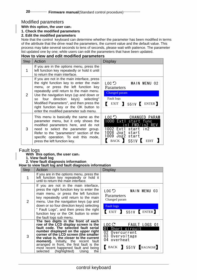
Modified parameters With this option, the user can:
1. Check the modified parameters 2. Edit the modified parameters Note that the control keyboard can determine whether the parameter has been modified in terms of the attribute that the drive read the parameters, the current value and the default value. This process may take several seconds to tens of seconds, please wait with patience. The parameter list updated one by one; while users can edit the parameters that have been updated.
How to view and edit modified parameters
Step Action Display
1
If you are in the options menu, press the left function key repeatedly or hold it until to return the main interface.
2
If you are not in the main interface, press the right function key to enter the main menu, or press the left function key repeatedly until return to the main menu. Use the navigation keys (up and down or so four direction keys) selecting" Modified Parameters", and then press the right function key or the OK button to enter the modified parameter sub menu.
3
This menu is basically the same as the parameter menu, but it only shows the modified parameters here, and do not need to select the parameter group. Refer to the "parameters" section of the specific operation. To exit this mode, press the left function key.
Fault logs With this option, the user can: 1. View fault log 2. View fault diagnosis information
How to view fault log and fault diagnosis information
Step Action Display
1 If you are in the options menu, press the left function key repeatedly or hold it until to return the main interface.
2
If you are not in the main interface, press the right function key to enter the main menu, or press the left function key repeatedly until return to the main menu. Use the navigation keys (up and down or so four direction keys) selecting " Fault Logs", and then press the right function key or the OK button to enter the fault logs sub menu.
3
The two digits in the front of each row of the LCD display screen is the fault code. The selected fault serial number displayed on the upper right corner of the LCD screen (the smaller the value is, the closer to the current moment). Initially, the recent fault arranged in front, the first fault is the most recent happened fault and being selected (highlighted) Using the
LOC CHANGED PARAM
【返回】 【编辑】551V
1002 Ext1 start in21008 Jog1 start1009 Jog2 start
LOC MAIN MENU 02
【退出】 【进入】551V
参数列表
故障日志
Parameters Changed param
Fault logs
EXIT ENTER
BACK EDIT
LOC FAULT LOGS 01
【返回】 【诊断】551V
02 Overcurrent03 Overvoltage04 overheat
LOC MAIN MENU 03
【退出】 【进入】551V
参数列表修改过的参数Parameters Changed param
Fault logs
EXIT ENTER
BACK DIAGNOSE

--------------- Firmware manual(Standard control procedure)--------------- 21
control keyboard
Step Action Display navigation keys (up and down or so four direction keys) to select the specified fault.
4
Press the right function key or the OK button to view the fault diagnosis information, Fault Code is displayed in the upper right corner of the LCD display. If the diagnostic information is empty, the LCD screen center will display ”No details”, means there is no detailed information about the selected fault.
5
If the length of the fault diagnosis information exceeds the length of information that the LCD screen can display, use the navigation keys (up and down or so four direction keys) to view the remaining content. To exit this mode, press any of the three function keys, the left and right function keys and the OK button, will do.
LOC FAULT CODE 02
【返回】 【确定】551V
0103 Mot current10.0 A
0102 DC-Link volt740.0 V
0100 Motor speed
LOC FAULT CODE 02
【返回】 【确定】551V
0102 DC-Link volt740.0 V
0100 Motor speed1500.0 RPM
0500 Run time
BACK OK
BACK OK

22--------------- Firmware manual(Standard control procedure)---------------
control keyboard
Assistants With assistants options, users can:
Select application macros
Set-up motor parameters
Setting up the drive start-stop control parameters
Assistant option contrast in both Chinese and English
Select app macro 选择应用宏
Set-up motor 设置电机参数
Start/Stop control 起停控制命令
How to use an assistant to select an application macro
Step Action Display
1 If you are in the options menu, press the left function key repeatedly or hold it until return to the main interface.
2
If you are in the main interface, press the right function key to enter the main menu, or press the left function key repeatedly until return to the main menu. Use the navigation keys (up and down or so four direction keys) selecting " Assistant", and then press the right function key or the OK button to enter the assistant sub menu.
3
Use the up and down arrow keys to select the "select application macros ", press the right function key or the OK button to enter the parameter edit mode. Refer to the "how to modify the value of the enumeration type parameters" section for specific operation. To exit this mode, press the left function key.
How to use the assistant to set the motor parameters and the drive start-stop control
parameters.
After entering the assistant menu, use the up and down arrow keys to select the
corresponding option, press the right function key or the OK button, then the control
keyboard will guide the user to set the relevant parameters in turn. After setting all
parameters, the control keyboard will pop up with the prompt message "operation
completed".
Parameters backup With this option, the user can:
Upload parameters to local (parameter copy)
Transfer parameters to drive (parameter download)
How to upload parameters to local (parameter copy)
Step Action Display
1 If you are in the options menu, press the left function key repeatedly or hold it until return to the main interface.
LOC ASSISTANTS 01
【返回】 【选择】551V
设置电机参数起停控制命令
LOC MAIN MENU 05
【退出】 【进入】551V
参数变更日志故障日志Fault logsPRM CHG
LOGS
ASSISTANTS
Select app macro
EXIT
Set-up motorStart/Stop
control
ENTER
BACK SELECT

--------------- Firmware manual(Standard control procedure)--------------- 23
control keyboard
2
If you are in the main interface, press the right function key to enter the main menu, or press the left function key repeatedly until return to the main menu. Use the navigation keys (up and down or so four direction keys) selecting " Parameter backup", and then press the right function key or the OK button to enter the parameter backup sub menu.
3
Use the up and down arrow keys to select the "parameter upload to the local", press the right function key or the OK button to start the parameter copy.
4
Copy parameters is executed by groups, the
first line shows the current executing task,read or save the parameter group, preceding the slash is the parameter group number currently in copy, behind the slash is the total number of the parameter groups. The second progress bar indicates the task execution schedule. The third line shows the prompt message, for example, ”timeout”(overtime), the rightmost number represents the index of the currently reading parameter. After the completion of the copy, the lower right corner will show “finish”.
How to transfer parameters to drive (parameter download)
Step Action Display
1 Omission
2
Use the up and down arrow keys to select "parameter download to the drive", press the right function key or OK button to start the parameter download.
3
Download parameters is also executed by groups.Firstly loading the parameter values from the local memory, followed with the CRC check, then compare with the parameter value range, then start to download the current parameter group after CRC check correct and no data overflow. The first line shows the current executing task, i.e. loading, inspection, writing parameter group, the rest similar with parameter copy.
Instruction on Parameter Backup Hints Overwrite?: Effective copy data already exists in control keyboard memory, whether to cover?
Timeout!: Overtime. Communication has no respond more than 3 seconds, copy or download
interrupted.
NVM empty!: Control keyboard has not been a parameter copy, memory is empty, refused to
download.
LOC MAIN MENU 06
【退出】 【进入】551V
助手
系统信息
LOC PRM UPLOAD
【取消】 【 】551V
Read group 01/63
01
LOC PARAM BACKUP 01
【退出】 【进入】551V
参数下传
LOC PRM DOWNLOAD
【取消】 【 】551V
Load group 01/63
01
LOC PARAM BACKUP 02
【退出】 【进入】551V
参数上传
Assistants Param backup
System info
EXIT ENTER
EXIT ENTER
CANCEL
Parameter upload
Parameter transfer
EXIT ENTER
Parameter Transfer
Parameter Upload
CANCEL

24--------------- Firmware manual(Standard control procedure)---------------
control keyboard
Data incomplete!: Control keyboard memory has copied data, but not complete, refused to download.
Drive unmatch: Drive type and model are inconsistent, refused to download.
Data check error: CRC check error occurred while loading parameter values from the control keyboard
storage, download interrupted.
Data overflow!: The previous copy of the parameter value exceeded the parameter range, download
interrupted.
Exceed NVM capacity: The address exceeded the capacity of the control keyboard memory when the
parameter value is saved, copy interrupted.
SYSTEM INFO With system information options, users can:
View the information of the drive manufacturer, model, firmware version, production date and
serial number, etc.
View the firmware version and diagnostic information of the control keyboard.

--------------- Firmware manual(Standard control procedure)--------------- 25
control keyboard
System information in Chinese and English
Drive 驱动器
Panel 控制键盘
How to view the information of drive manufacturer, model, firmware version,
production date and serial number, etc.
Step Action Display
1 If you are in the options menu, press the left function key repeatedly or hold it until return to the main interface.
2
If you are in the main interface, press the right function key to enter the main menu, or press the left function key repeatedly until return to the main menu. Use the navigation keys (up and down or so four direction keys) selecting "System Info", and then press the right function key or the OK button to enter the system information sub menu.
3
Use the up and down arrow keys to select "drive", press the right function key or the OK button to view the drive manufacturer, model, firmware version, serial number and other information.
4
Initially, the second line of the LCD screen shows the name of the drive manufacturer; the fourth line shows the product model. Press the navigation keys (up and down or so four direction keys) for scrolling and page turning, browse the remaining content. To exit this mode,press any of the three functions, the left and right function keys and the OK button, will do.
How to view the firmware version and the diagnostic information of the
control keyboard
Step Action Display
1 If you are in the options menu, press the left function key repeatedly or hold it until return to the main interface.
2
If you are in the main interface, press the right function key to enter the main menu, or press the left function key repeatedly until return to the main menu. Use the navigation keys (up and down or so four direction keys) selecting "System Info", and then press the right function key or the OK button to enter the system information sub menu.
3
Use the up and down arrow keys to select "control keyboard", press the right function key or the OK button to view the firmware version and the diagnostic information of the control keyboard.
LOC SYSTEM INFO 01
【返回】 【选择】551V
控制键盘
LOC MAIN MENU 07
【退出】 【进入】551V
助手参数备份
LOC DRIVE INFO
【返回】 【确定】551V
Manufacturer******
Drive modelXXXXX-01-2K2G-3
Firmware ver
LOC MAIN MENU 07
【退出】 【进入】551V
助手参数备份
LOC SYSTEM INFO 02
【返回】 【选择】551V
AssistantsParam
backup
System Info
Drive
Supervisory Keyboard
Supervisory Keyboard
Drive
AssistantsParam
backup
EXIT ENTER
BACK SELECT
BACK OK
EXIT ENTER
SELECT BACK
System Info
26--------------- Firmware manual(Standard control procedure)---------------
control keyboard
4
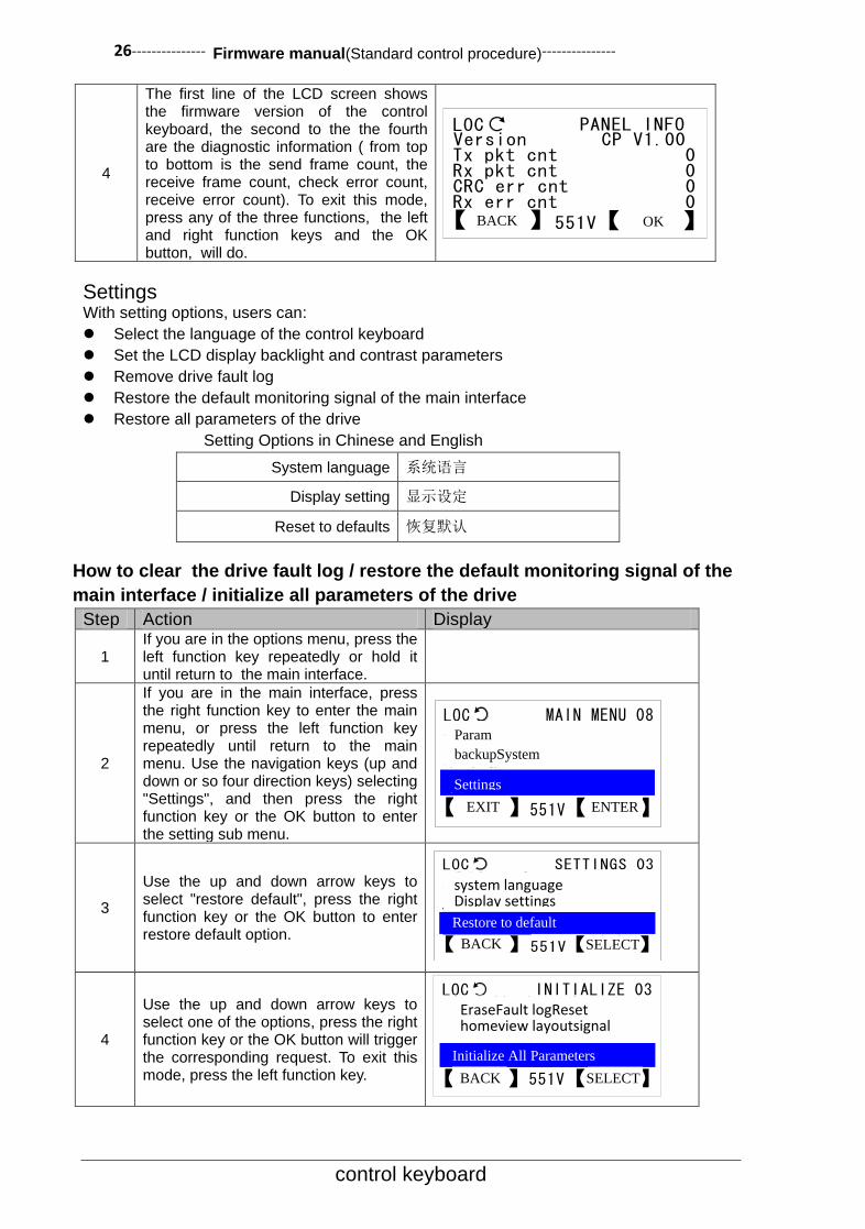
The first line of the LCD screen shows the firmware version of the control keyboard, the second to the the fourth are the diagnostic information ( from top to bottom is the send frame count, the receive frame count, check error count, receive error count). To exit this mode, press any of the three functions, the left and right function keys and the OK button, will do.
Settings With setting options, users can:
Select the language of the control keyboard
Set the LCD display backlight and contrast parameters
Remove drive fault log
Restore the default monitoring signal of the main interface
Restore all parameters of the drive
Setting Options in Chinese and English
System language 系统语言
Display setting 显示设定
Reset to defaults 恢复默认
How to clear the drive fault log / restore the default monitoring signal of the
main interface / initialize all parameters of the drive
Step Action Display
1 If you are in the options menu, press the left function key repeatedly or hold it until return to the main interface.
2
If you are in the main interface, press the right function key to enter the main menu, or press the left function key repeatedly until return to the main menu. Use the navigation keys (up and down or so four direction keys) selecting "Settings", and then press the right function key or the OK button to enter the setting sub menu.
3
Use the up and down arrow keys to select "restore default", press the right function key or the OK button to enter restore default option.
4
Use the up and down arrow keys to select one of the options, press the right function key or the OK button will trigger the corresponding request. To exit this mode, press the left function key.
LOC PANEL INFO
【返回】 【确定】551V
Version CP V1.00Tx pkt cnt 0Rx pkt cnt 0CRC err cnt 0Rx err cnt 0
LOC MAIN MENU 08
【退出】 【进入】551V
参数备份系统信息
LOC SETTINGS 03
【返回】 【选择】551V
系统语言显示设定
LOC INITIALIZE 03
【返回】 【选择】551V
清除故障日志恢复主界面信号
EraseFault logReset homeview layoutsignal
BACK OK
Param
backupSystem
info Settings
EXIT ENTER
system language Display settings
Restore to default
BACK SELECT
Initialize All Parameters
BACK SELECT

--------------- Firmware manual(Standard control procedure)--------------- 27
control keyboard
Restore the default option in Chinese and English
Erase fault logs 清除驱动器故障日志
Reset homeview layout 恢复主界面信号
Reset all parameters 初始化所有参数
Note:In order to prevent user misoperation result in data loss, when the user performs this part of operation, the control keyboard will pop up the following tips box. Only the user presses the right function key or the OK button to confirm, will the operation be executed.
Option Menu Mode In this mode, the basic operation is the same as the main menu mode. Before reading this
part, please read carefully the front chapters.
Local Given This option is used to edit the local given value. User must press the right function key or
the OK button to save, then the change will take effect. If and only when the drive is in a
local control mode or a given source selection control keyboard is given, can the users use
this option. For specific operation please refer to "how to modify value of the numerical
type parameters" section.
Motor Rotation Direction This option is used to switch the rotation
direction of the motor. As shown on the right
picture, the center of the LCD screen shows the
current motor rotation direction (Forward
represents Corotation, Reverse represents
Reversion) A line of prompt is shown below to
tell the user to press the left or the right direction
key to switch the direction.
Edit Main Interface How to select a monitoring signal and view or edit its input source
Step Action Display
1 If you are in the options menu, press the left function key repeatedly or hold it until return to the main interface.
LOC DIRECTION
正转
【返回】 【确定】551V
按向左或向右键切换电机旋转方向。
LOC
【取消】 【确定】551V
CAUTION!本操作会导致用户数据丢失,是否继续?
MESSAGE
Press the left or the right function key to switch the motor rotation direction
CANCLE
EL
OK
This operation will lead to user data loss,
whether to continue?
Corotation
BACK OK
28--------------- Firmware manual(Standard control procedure)---------------
control keyboard
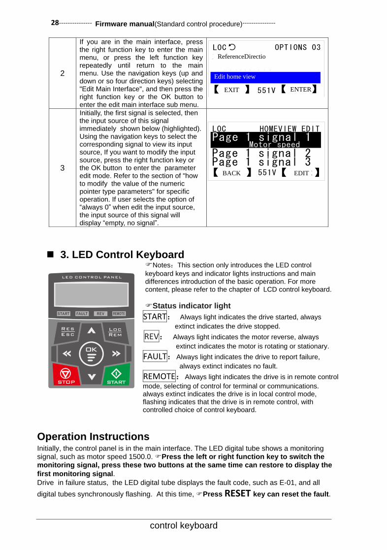
3. LED Control Keyboard Notes:This section only introduces the LED control
keyboard keys and indicator lights instructions and main differences introduction of the basic operation. For more content, please refer to the chapter of LCD control keyboard.
Status indicator light
START: Always light indicates the drive started, always
extinct indicates the drive stopped. REV: Always light indicates the motor reverse, always
extinct indicates the motor is rotating or stationary.
FAULT:Always light indicates the drive to report failure,
always extinct indicates no fault.
REMOTE:Always light indicates the drive is in remote control
mode, selecting of control for terminal or communications. always extinct indicates the drive is in local control mode, flashing indicates that the drive is in remote control, with controlled choice of control keyboard.
Operation Instructions Initially, the control panel is in the main interface. The LED digital tube shows a monitoring signal, such as motor speed 1500.0. Press the left or right function key to switch the monitoring signal, press these two buttons at the same time can restore to display the
first monitoring signal. Drive in failure status, the LED digital tube displays the fault code, such as E-01, and all
digital tubes synchronously flashing. At this time, Press RESET key can reset the fault.
2
If you are in the main interface, press the right function key to enter the main menu, or press the left function key repeatedly until return to the main menu. Use the navigation keys (up and down or so four direction keys) selecting "Edit Main Interface", and then press the right function key or the OK button to enter the edit main interface sub menu.
3
Initially, the first signal is selected, then the input source of this signal immediately shown below (highlighted). Using the navigation keys to select the corresponding signal to view its input source, If you want to modify the input source, press the right function key or the OK button to enter the parameter edit mode. Refer to the section of "how to modify the value of the numeric pointer type parameters" for specific operation. If user selects the option of “always 0” when edit the input source, the input source of this signal will display “empty, no signal”.
LOC OPTIONS 03
【退出】 【进入】551V
电机旋转方向本地给定
LOC HOMEVIEW EDIT
【编辑】【返回】 551V
Page 1 signal 2Page 1 signal 3
ReferenceDirectio
EXIT
Edit home view
ENTER
BACK EDIT
--------------- Firmware manual(Standard control procedure)--------------- 29
control keyboard
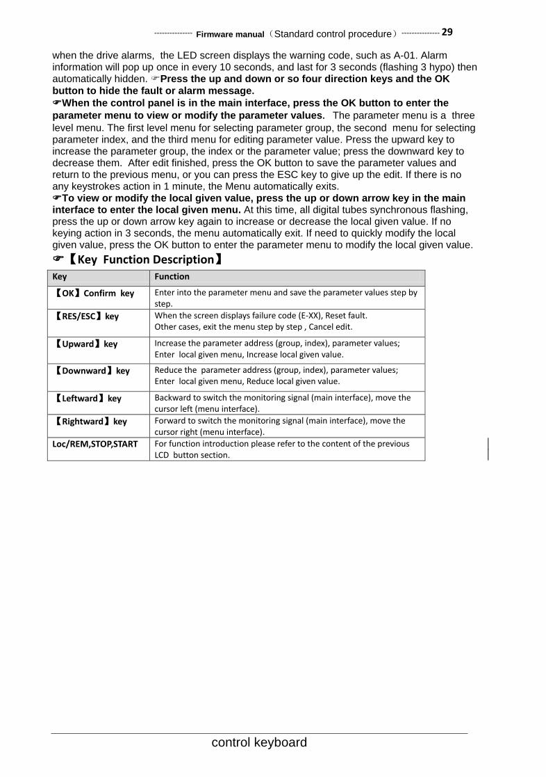
when the drive alarms, the LED screen displays the warning code, such as A-01. Alarm information will pop up once in every 10 seconds, and last for 3 seconds (flashing 3 hypo) then automatically hidden. Press the up and down or so four direction keys and the OK
button to hide the fault or alarm message. When the control panel is in the main interface, press the OK button to enter the
parameter menu to view or modify the parameter values. The parameter menu is a three
level menu. The first level menu for selecting parameter group, the second menu for selecting parameter index, and the third menu for editing parameter value. Press the upward key to increase the parameter group, the index or the parameter value; press the downward key to decrease them. After edit finished, press the OK button to save the parameter values and return to the previous menu, or you can press the ESC key to give up the edit. If there is no any keystrokes action in 1 minute, the Menu automatically exits. To view or modify the local given value, press the up or down arrow key in the main interface to enter the local given menu. At this time, all digital tubes synchronous flashing, press the up or down arrow key again to increase or decrease the local given value. If no keying action in 3 seconds, the menu automatically exit. If need to quickly modify the local given value, press the OK button to enter the parameter menu to modify the local given value.
【Key Function Description】 Key Function
【OK】Confirm key Enter into the parameter menu and save the parameter values step by step.
【RES/ESC】key When the screen displays failure code (E-XX), Reset fault. Other cases, exit the menu step by step , Cancel edit.
【Upward】key Increase the parameter address (group, index), parameter values; Enter local given menu, Increase local given value.
【Downward】key Reduce the parameter address (group, index), parameter values; Enter local given menu, Reduce local given value.
【Leftward】key Backward to switch the monitoring signal (main interface), move the cursor left (menu interface).
【Rightward】key Forward to switch the monitoring signal (main interface), move the cursor right (menu interface).
Loc/REM,STOP,START For function introduction please refer to the content of the previous LCD button section.

30--------------- Firmware manual(Standard control procedure)---------------
Program Function
4.Program Function Control Place The Loc/Rem button on the control keyboard can switch between the two modes of local and remote.
Local Control Local control is used for site debugging, maintenance or simple application. At this point the system start-stop control is decided by the START and STOP button of the LCD panel. With the Parameter 16.00 Local lock (local control locking) to ban the use of control mode switching to local control.
Remote Control When remote control mode used for practical application, the system start-stop depends on the terminal input or communication instruction, etc.; Speed given depends on analog input, or communication instruction, or process PID control output, Multi segment speed setting, etc. It can provide two remote control place, EXT1 and EXT2. With two kinds of external control place, user can select the control signal (for example, start & stop) and the control mode. According to the user's choice, EXT1 or EXT2 can be activated. User can select EXT1/EXT2 by digital input or fieldbus control.
Start Stop Control
Start Stop Logic
启停状态机
Ready
STOPPED
RUNNING
FAULTED
06.00 Drive status word1
06.01 Drive status word2
06.02 Drive status word3
11.00 Stop mode
10.13 Em Stop sel
10.14 Em Stop mode
10.11 Fault reset sel
10.12 Ext Run enable
06.00.06 start request
06.00.07 stop request
EXT1 start request
EXT2 start request
11.01 EXT1/EXT2 sel
EXT start req
06.00.08 Jog start
Local start
LOC/REM sel10.15 start enable
06.00.06 start request
启动请求逻辑
The drive can start from the following four ways: 1) in local control status, Start from LCD panel; 2) in
remote control status, Start from the extral control place EXT1; 3) in remote control status, Start from the
extral control place EXT2; 4) jog start, as shown in the figure above.
EXT1 start request indicates the start request signal of external control place1, EXT2 start request indicates the start request signal of external control place2. The parameter11.01 EXT1/EXT2 sel used for selection of control place, user can set it as fixed value such as EXT1 or EXT2, can also set the terminal
Start stop state
Start request logic

--------------- Firmware manual(Standard control procedure)--------------- 31
Program Function
signal from DI1 to DI7 to achieve flexible switching for control place. With all the start command of starting mode summarized, user can also execute the control by starting the enable master switch. Only when the parameter 10.15 start enable (Start enable) is effective can start command to be executed, otherwise if the parameter is invalid, the drive will shutdown unconditionally.
Jog Start Jog start has two signal sources, they are respectively as 10.08 Jog1 start (Jog1 start) and 10.09 Jog2 start (Jog2 start). When the two jog commands are effective at the same time, the jog command JOG1 is prioritized. User can enable or disable the jog function with the parameter 10.10 Jog enable (Jog enable) . Note: local control does not provide jog function.
10.08 Jog1 start
10.09 Jog2 start
10.10 Jog enable
06.00.08 Jog active
非点动运行中,点动命令不执行
点动逻辑
When the jog signal is valid, and if the drive is stopped, then jog the start command signal will also start the drive; When the drive is already in operation, the command will not be executed. When the jog command is activated, the start command signal from external control place will not be executed until the jog is completely stopped. See figure below.
Point move command JOG1
Point move command JOG2
External run command
Dynamic
activation
Dynamic velocity
Modulation output
1 2 3 4 5 6 7 8 9 10 11
When the drive is in operation, the shutdown signals are as follows: 1) lost start command; 2) receive emergency stop command; 3) lost of operation enable signal; 4) drive failure. When meet with any of the above conditions, the drive will be shut down.
Emergency Shutdown For emergency shutdown, the shutdown mode depends on the parameters of 10.14 Em stop mode (Em stop mode), the default is free shutdown. The signal source for emergency shutdown can be selected by the parameters of 10.13 Em stop sel. The deceleration time for emergency shutdown depends on the parameters of 22.04 Em stop time (emergency shutdown time).
Fault Shutdown For fault shutdown, mostly they take the free shutdown mode. The below three fault shutdown modes depend on the parameters of 11.00 Stop mode: 1) Process PID control feedback disconnection; 2) Analog input disconnection; 3) Running time limited. When the fault is triggered, if the startup command still exists, for non level triggered mode (See parameter of 11.05 Ext1 Trig type, 11.06 Ext trig type), even if the fault has been cleared, the system is still banned to start until the start command is removed and then start again. The fault clearing mode can be achieved by: 1) panel buttons; 2) the rising edge of the specified signal by the parameter of 10.11 Fault reset sel; 3) auto reset function; 4) power off.
External Control Place The system provides two completely independent external controls, each of which corresponds to a startup
Jog Logic
Non jog operation, the jog
command not be executed.

32--------------- Firmware manual(Standard control procedure)---------------
Program Function
function, speed/ torque control mode, as well as the speed/ torque given, can be configured flexibly to meet the field applications. The startup signal combination mode of the two controls depends on the parameters of 10.00 Ext1 start func and 10.04 Ext2 start func, which including the two-wire control, three-wire control, communication control, panel control, see figure as below.
10.00 Ext1 start func
6: Panel
0: Not select
1: In1 start, In2 dir
2: In1 fwd, In2 rev
3: In1 start, In2 stop, In3 dir
4: In1 fwd, In2 rev, In3 stop
5: FieldBus
10.01 Ext1 In1 sel
10.02 Ext1 In2 sel
10.03 Ext1 In3 sel
EXT1 start request
EXT1 stop request
Control to 1 start-stop
11.05 Ext1 Trig Type
10.04 Ext2 start func
10.05 Ext2 In1 sel
10.06 Ext2 In2 sel
10.07 Ext2 In3 sel
EXT2 start request
EXT2 stop request
6: Panel
0: Not select
1: In1 start, In2 dir
2: In1 forward, In2 rev
3: In1 start, In2 stop, In3 dir
4: In1 fwd, In2 rev, In3 stop
5: FieldBus
Control to 2 start-stop
11.06 Ext2 Trig Type
Terminal Two-wire, Three-wire Control Take the external control 1 as an example, choose 1 or 2 for the parameter of 10.00 Ext1 start func (External control 1 startup function), the corresponding terminal is two-wire control system; Choose 3 or 4, the corresponding terminal is three-wire control system. The signal source for two-wire or three-wire control is selected by the parameters of 10.01 Ext1 In1 sel, 10.02 Ext1 In2 sel, 10.03 Ext1 In3 sel. User can edit the pointer which will be designated as any one of the digital input terminals, also can be specified for any timer or any signal. The parameter of 11.05 Ext1 Trig Type is used for setting the signal type of In1, In, In3 should be edge signal or level signal. This parameter is for two-wire control only; three-wire control is always the edge trigger.
Speed/Torque Control For local control, user can only can select the speed or torque control mode. The external control mode can be specified as speed, torque, speed and torque combination, positioning and other modes. The parameter of 11.02 Ext1 Ctrl Mode is used for the control mode of specified external control 1; the parameter of 11.03 Ext2 Ctrl Mode is used for the control mode of specified external control 2; the parameter of 11.04 Loc Ctrl Mode is used for the control mode of local control. The actual implementation of the control mode can be checked by the parameters of 03.05 Ctrl mode used. The selection and switching for speed torque control mode is shown as below.
Note: for the torque mode, when a request for shutdown is encountered, the control mode will be forced to speed mode.

--------------- Firmware manual(Standard control procedure)--------------- 33
Program Function
11.02 Ext1 Ctrl Mode
11.03 Ext2 Ctrl Mode
11.01 EXT1/EXT2 sel
EXT ctrl mode
11.04 Local Ctrl Mode
LOC/REM sel
03.05 Ctrl mode used
Control mode
selection
Speed Given As the following figure shows, there are two signal sources for the general speed given of the drive which are respectively Speed Given 1 (parameter 21.00 speed ref1 src), Speed given 2 (parameter21.01 speed ref2 src). These two signal sources can execute compositional operation (parameter 21.02 speed ref func), at the same time can be switched (parameter21.03 speed ref sel), and then gain by speed given distribution (parameter 21.04 speed share). When the multi speed terminal is effective, as for the multi speed priority, the speed given will automatically switch to multi speed (parameter 03.02 const speed out). When the jog2 is activated (10.09 JOG2 start), the speed given is modified to jog speed2 (parameter 21.05 Jog2 spd ref); when the jog 1 is activated (10.08 JOG1 start), the speed given is modified to jog speed 1 (parameter 21.06 Jog1 spd ref); When the local control is activated (06.00.15 Local ctrl, the upper left corner of the panel displays “LOC”), the speed given is modified to panel given 1 (parameter 28.02 Panel ref1). When the speed jump is enabled (parameter 25.06 Crit spd sel), the output of the speed given is limited by the jump speed limit (parameter 25.00 to 25.05). The speed given is also subject to the maximum speed limit (parameter 20.00 spd ref max), the minimum speed limit (parameter 20.01 spd ref min), the positive and negative enable limit (parameter 20.02 Pos spd ena, 20.03 Neg spd ena) . The final given of the speed refer to the parameter 03.00 spd ref out.
The general speed given1 and the general speed given 2 can not only choose the conventional signal (Analog, multi speed, high-speed pulse input, bus communication, electric potentiometer, panel given, etc.), but also select any signal by the user-defined edit pointer.
Analog Input Speed Given Refer to the content of the Control Interface Section on analog inputs (AI1, AI2, AI3).
High-Speed Pulse Input Speed Given Refer to the content of the Control Interface Section on high-speed pulse input (DI7).
Communication Speed Given Refer to the Field Bus Chapter.

34--------------- Firmware manual(Standard control procedure)---------------
Program Function
21
.00
sp
ee
d r
ef1
src
Fie
ld b
us r
ef1
Ze
ro
AI1
sca
led
AI2
sca
led
AI3
sca
led
Co
nst sp
ee
d o
ut
Pro
ce
ss P
ID o
ut
Pa
ne
l re
f2
Mo
t p
ot o
ut
Pu
lse
fre
q o
ut
Fie
ld b
us r
ef2
Pa
ne
l re
f1
Po
inte
r
21
.01
sp
ee
d r
ef2
src
Fie
ld b
us r
ef1
Ze
ro
AI1
sca
led
AI2
sca
led
AI3
sca
led
Co
nst sp
ee
d o
ut
Pro
ce
ss P
ID o
ut
Pa
ne
l re
f2
Mo
t p
ot o
ut
Pu
lse
fre
q o
ut
Fie
ld b
us r
ef2
Pa
ne
l re
f1
Po
inte
r
0: R
ef1
1: A
dd
2: S
ub
3: M
ul
4: M
in
5: M
ax
21
.02
Sp
ee
d r
ef fu
nc(
Re
f1O
pe
ratio
n
typ
e)
21
.03
Sp
ee
d r
ef se
l
×
21
.04
Sp
ee
d s
ha
re(
Sp
ee
d g
ive
n
dis
trib
utio
n)
Co
nst sp
ee
d c
md
03.0
2 C
on
st sp
ee
d o
ut
10
.08
Jo
g1
sta
rt
10
.09
Jo
g2
sta
rt
21
.05
Jo
g2
sp
d r
ef
21
.06
Jo
g1
sp
d r
ef
28
.02
Pa
ne
l re
f1
06
.00.1
5 L
oca
l C
trl
25
.06
Crit sp
d s
el
25.0
0 C
rit sp
d1
Lo
25
.01
Crit sp
d1
Hi
20
.00
Sp
d r
ef m
ax
20
.01
Sp
d r
ef m
in Sp
eed
lim
itin
gP
osi
tive
invers
ion
20.0
2 P
os s
pd
en
a
20
.03
Ne
g s
pd
en
a
03
.00
Sp
d r
ef o
ut

--------------- Firmware manual(Standard control procedure)--------------- 35
Program Function
Multi Speed Multi speed function supports 4 selection signals (see parameter 26.18 Const speed sel1, 26.19 Const speed sel2, 26.20 Const speed sel3, 26.21 Const speed sel), also can support the combination or separation mode (see parameter 26.16 Const speed mode). The combination mode is consist of 4 selected signals with a combination of 16 options, which are corresponding to 16 segment speed (see parameter 26.00 Const speed_0 to 26.15 Const speed_15), the separation mode is consist of 4 selected signals which corresponding to 5 segment speed (see parameter 26.00 Const speed_0 to 26.15 Const speed_4).
26.18 Const speed sel1
26.19 Const speed sel2
26.20 Const speed sel3
26.21 Const speed sel4
03.02 Const speed out
26.16 Const speed mode
26.00 Const speed_0
26.15 Const speed_15
Combination mode(26.16 Const speed mode = 0):
Multi speed choice1 26.18 Const speed sel1
Multi speed choice2 26.19 Const speed sel2
Multi speed choice3 26.20 Const speed sel3
Multi speed choice4 26.21 Const speed sel4
Multi speed
output
0 0 0 0 Constvelocity0
1 0 0 0 Constvelocity1
0 1 0 0 Constvelocity2
1 1 0 0 Constvelocity3
0 0 1 0 Constvelocity4
1 0 1 0 Constvelocity5
0 1 1 0 Constvelocity6
1 1 1 0 Constvelocity7
0 0 0 1 Constvelocity8
1 0 0 1 Constvelocity9
0 1 0 1 Constvelocity10
1 1 0 1 Constvelocity11
0 0 1 1 Constvelocity12
1 0 1 1 Constvelocity13
0 1 1 1 Constvelocity14
1 1 1 1 Constvelocity15
Discrete model(26.16 Const speed mode = 1):
Multi speed
choice1 26.18 Const speed sel1
Multi speed
choice2 26.19 Const speed sel2
Multi speed
choice3 26.20 Const speed sel3
Multi speed
choice4 26.21 Const speed sel4
Multi speed
output
0 0 0 0 Constvelocity0
1 x x x Constvelocity1
0 1 x x Constvelocity2
0 0 1 x Constvelocity3
0 0 0 1 Constvelocity4

36--------------- Firmware manual(Standard control procedure)---------------
Program Function
Electric Potentiometer(also named as terminal acceleration and deceleration function) The electric potentiometer is often used for manual speed control, or fine tuning speed. When the input signal increase progressively of the potentiometer (parameter 21.08 Mot pot up) is valid, the integrator accumulate points upwards; When the input signal decrease progressively of the potentiometer (parameter 21.09 Mot pot down) is valid, the integrator accumulate points downward. The integral time of the integrator depends on the parameters of 21.12 Mot pot ramp time, i.e. time required from the minimum value points to the maximum. There are two types of storage mode of the integrator (parameter 21.07 Mot pot mode): 1)Shutdown reset, power off does not save; 2) Shutdown is not cleared, power off saves. The output of the integrator is limited by the amplitude limiting module, the maximum output value depends on the parameters of 21.10 Mot pot max, while the minimum output value depends on the parameters of 21.11 Mot pot min, the actual output of the electric potentiometer is stored in the parameters of 03.01 Mot pot out. When the speed given need to use the electric potentiometer output, please take the first speed given source 21.00 spd ref1 source point to the parameter of 03.01 Mot pot out. When the electric potentiometer output acts as a fine-tuning mode, Please take the second speed given source 21.01 spd ref2 source point to the parameter of 03.01 Mot pot out, then set the synthesis method of the speed given (parameter of 21.02 spd ref1 func) by Add, i.e. speed given 1 and speed given 2 are added as the actual speed given.
21.08 Mot pot up
21.09 Mot pot down
03.01 Mot pot outintegrator
21.12 Mot pot ramp time
21.10 Mot pot max
21.11 Mot pot min
Limiting
21.07 Mot pot mode
Speed Given Ramp Generator Ramp generator is used for speed control. According to the user set acceleration and deceleration time and the S curve time to produce ramp speed given signal, and take this as speed input for the speed regulator. The drive provides two sets of acceleration and deceleration time for selection, the first set of acceleration and deceleration time is determined by the parameters of 22.00 Acc time1, 22.01 Dec time1; the second set of acceleration and deceleration time is determined by the parameters of 22.02 Acc time2, 22.03 Dec time2. The switching of the two sets of the acceleration and deceleration time is determined by the parameters of 22.12 RampTimeSel. Upon invalid status select the first group, while in valid status select the second set of acceleration and deceleration time. User can always select the first group, or always select the second group, can also specify a signal by the bit pointer, such as digital input terminal DI3. The jog acceleration and deceleration time has a higher priority. When the jog is activated, the actual acceleration and deceleration time is switched into the jog acceleration and deceleration time. See the parameters of 22.04 Jog Acc time, 22.05 Jog dec time. Emergency stop has a higher priority than the ordinary stop and the jog stop, thus when encounter with emergency stop, the actual acceleration and deceleration time will be switched to emergency stop time, refer to parameter of 22.06 EM stoptime.
The ramp input is for the output of speed given module 03.00 Spd ref out, Ramp output is 03.04 Spd ref ramp out, used for the input of the speed controller. S Curve is invalid at jog or emergency stop. The setting for S Curve time refers to the parameters of 22.07, 22.08, 22.09, 22.10.
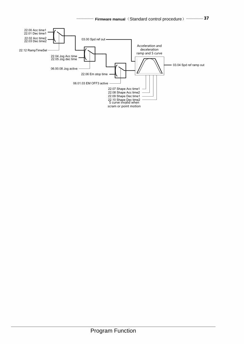
--------------- Firmware manual(Standard control procedure)--------------- 37
Program Function
Acceleration and deceleration
ramp and S curve
22.00 Acc time122.01 Dec time1
22.02 Acc time222.03 Dec time2
22.12 RampTimeSel
22.04 Jog Acc time22.05 Jog dec time
06.00.08 Jog active
22.06 Em stop time
06.01.03 EM OFF3 active
03.00 Spd ref out
03.04 Spd ref ramp out
22.07 Shape Acc time1
22.08 Shape Acc time2
22.09 Shape Dec time1
22.10 Shape Dec time2S curve invalid when
scram or point motion
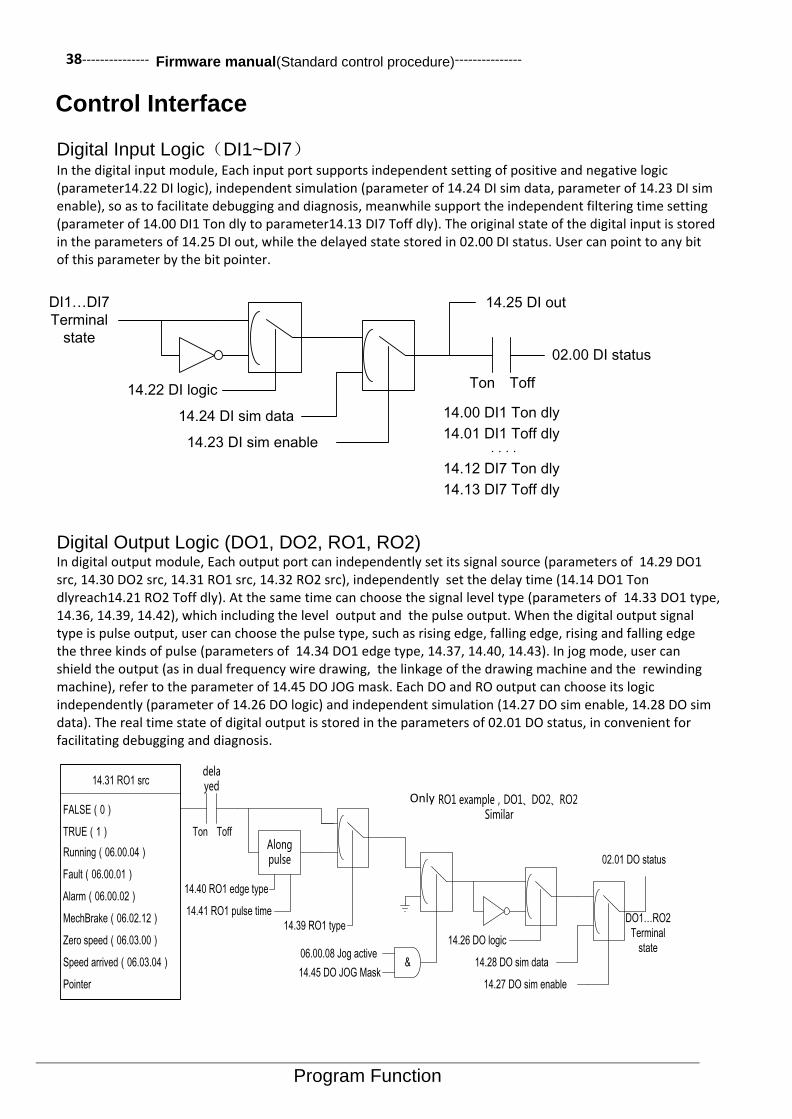
38--------------- Firmware manual(Standard control procedure)---------------
Program Function
Control Interface
Digital Input Logic(DI1~DI7) In the digital input module, Each input port supports independent setting of positive and negative logic (parameter14.22 DI logic), independent simulation (parameter of 14.24 DI sim data, parameter of 14.23 DI sim enable), so as to facilitate debugging and diagnosis, meanwhile support the independent filtering time setting (parameter of 14.00 DI1 Ton dly to parameter14.13 DI7 Toff dly). The original state of the digital input is stored in the parameters of 14.25 DI out, while the delayed state stored in 02.00 DI status. User can point to any bit of this parameter by the bit pointer.
DI1…DI7
Terminal
state
14.22 DI logic
14.24 DI sim data
14.23 DI sim enable
14.25 DI out
02.00 DI status
Ton Toff
14.00 DI1 Ton dly
14.01 DI1 Toff dly
14.12 DI7 Ton dly
14.13 DI7 Toff dly
Digital Output Logic (DO1, DO2, RO1, RO2) In digital output module, Each output port can independently set its signal source (parameters of 14.29 DO1 src, 14.30 DO2 src, 14.31 RO1 src, 14.32 RO2 src), independently set the delay time (14.14 DO1 Ton dlyreach14.21 RO2 Toff dly). At the same time can choose the signal level type (parameters of 14.33 DO1 type, 14.36, 14.39, 14.42), which including the level output and the pulse output. When the digital output signal type is pulse output, user can choose the pulse type, such as rising edge, falling edge, rising and falling edge the three kinds of pulse (parameters of 14.34 DO1 edge type, 14.37, 14.40, 14.43). In jog mode, user can shield the output (as in dual frequency wire drawing, the linkage of the drawing machine and the rewinding machine), refer to the parameter of 14.45 DO JOG mask. Each DO and RO output can choose its logic independently (parameter of 14.26 DO logic) and independent simulation (14.27 DO sim enable, 14.28 DO sim data). The real time state of digital output is stored in the parameters of 02.01 DO status, in convenient for facilitating debugging and diagnosis.
14.31 RO1 src
FALSE(0)
TRUE(1)
Running(06.00.04)
Fault(06.00.01)
Alarm(06.00.02)
Pointer
MechBrake(06.02.12)
Zero speed(06.03.00)
Speed arrived(06.03.04)
Ton Toff
delayed
14.39 RO1 type
Along pulse
14.40 RO1 edge type
14.41 RO1 pulse time
06.00.08 Jog active
14.45 DO JOG Mask&
14.26 DO logic
14.28 DO sim data
14.27 DO sim enable
02.01 DO status
仅以RO1 example,DO1、DO2、RO2 Similar
DO1…RO2
Terminal
state
Only
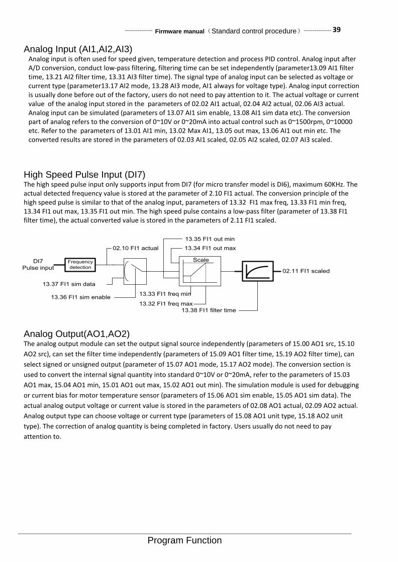
--------------- Firmware manual(Standard control procedure)--------------- 39
Program Function
Analog Input (AI1,AI2,AI3) Analog input is often used for speed given, temperature detection and process PID control. Analog input after A/D conversion, conduct low-pass filtering, filtering time can be set independently (parameter13.09 AI1 filter time, 13.21 AI2 filter time, 13.31 AI3 filter time). The signal type of analog input can be selected as voltage or current type (parameter13.17 AI2 mode, 13.28 AI3 mode, AI1 always for voltage type). Analog input correction is usually done before out of the factory, users do not need to pay attention to it. The actual voltage or current value of the analog input stored in the parameters of 02.02 AI1 actual, 02.04 AI2 actual, 02.06 AI3 actual. Analog input can be simulated (parameters of 13.07 AI1 sim enable, 13.08 AI1 sim data etc). The conversion part of analog refers to the conversion of 0~10V or 0~20mA into actual control such as 0~1500rpm, 0~10000 etc. Refer to the parameters of 13.01 AI1 min, 13.02 Max AI1, 13.05 out max, 13.06 AI1 out min etc. The converted results are stored in the parameters of 02.03 AI1 scaled, 02.05 AI2 scaled, 02.07 AI3 scaled.
High Speed Pulse Input (DI7) The high speed pulse input only supports input from DI7 (for micro transfer model is DI6), maximum 60KHz. The actual detected frequency value is stored at the parameter of 2.10 FI1 actual. The conversion principle of the high speed pulse is similar to that of the analog input, parameters of 13.32 FI1 max freq, 13.33 FI1 min freq, 13.34 FI1 out max, 13.35 FI1 out min. The high speed pulse contains a low-pass filter (parameter of 13.38 FI1 filter time), the actual converted value is stored in the parameters of 2.11 FI1 scaled.
DI7
Pulse input
02.10 FI1 actual
13.37 FI1 sim data
13.36 FI1 sim enable13.33 FI1 freq min
13.32 FI1 freq max
13.35 FI1 out min
13.34 FI1 out max
02.11 FI1 scaled
Scale
13.38 FI1 filter time
Frequency
detection
Analog Output(AO1,AO2) The analog output module can set the output signal source independently (parameters of 15.00 AO1 src, 15.10
AO2 src), can set the filter time independently (parameters of 15.09 AO1 filter time, 15.19 AO2 filter time), can
select signed or unsigned output (parameter of 15.07 AO1 mode, 15.17 AO2 mode). The conversion section is
used to convert the internal signal quantity into standard 0~10V or 0~20mA, refer to the parameters of 15.03
AO1 max, 15.04 AO1 min, 15.01 AO1 out max, 15.02 AO1 out min). The simulation module is used for debugging
or current bias for motor temperature sensor (parameters of 15.06 AO1 sim enable, 15.05 AO1 sim data). The
actual analog output voltage or current value is stored in the parameters of 02.08 AO1 actual, 02.09 AO2 actual.
Analog output type can choose voltage or current type (parameters of 15.08 AO1 unit type, 15.18 AO2 unit
type). The correction of analog quantity is being completed in factory. Users usually do not need to pay
attention to.

40--------------- Firmware manual(Standard control procedure)---------------
Program Function
15.00 AO1 src
Zero
P01.00 Speed display
P01.01 Freq display
P01.02 Udc actual
15.09 AO1 filter time
|x|
15.07 AO1 mode
15.04 AO1 min
15.03 AO1 max
15.02 AO1 out min
15.01 AO1 out max
Scale
15.05 AO1 sim data
15.06 AO1 sim enable
Calibration
32.16 AO1 gain
32.17 AO1 offset
0~10.000V
0~20.000mA
15.08 AO1 unit type
AO1, AO2
Analog
output
D/A
02.08 AO1 actual
P01.03 motor current
P01.04 motor current %
P01.12 motor slip
P01.22 motor torque
Pointer
High Speed Pulse Output (DO2) The high speed pulse output only supports DO2. The signal source of the high speed pulse output (parameter of 15.20 FO1 src) after filtering (parameter of 15.27 FO1 filter time) enter into conversion module (parameters of 15.21 FO1 out max, 15.22 FO1 out min, 15.23 FO1 src max, 15.24 FO1 src min). If enable the simulation (15.25 FO1 sim enable), then the output pulse frequency depends on the simulation settings (parameter of 15.26 FO1 sim data). The actual output pulse frequency is stored in the parameters of 02.11 FO1 actual. Note: since DO2 defaults to general digital output, if user needs to use the high-speed pulse output function, then need to enable the pulse generator (parameter of 15.28 FO1 enable).
15.20 FO1 src
15.27 FO1 filter time
15.24 FO1 min
15.23 FO1 max
15.22 FO1 out min
15.21 FO1 out max
Scale
15.26 FO1 sim data
15.25 FO1 sim enable
DO2
Pulse
output
Pulse
generator
02.11 FO1 actual
15.28 FO1 enable
Zero
P01.00 Speed display
P01.01 Freq display
P01.02 Udc actual
P01.03 motor current
P01.04 motor current %
P01.12 motor slip
P01.22 motor torque
Pointer
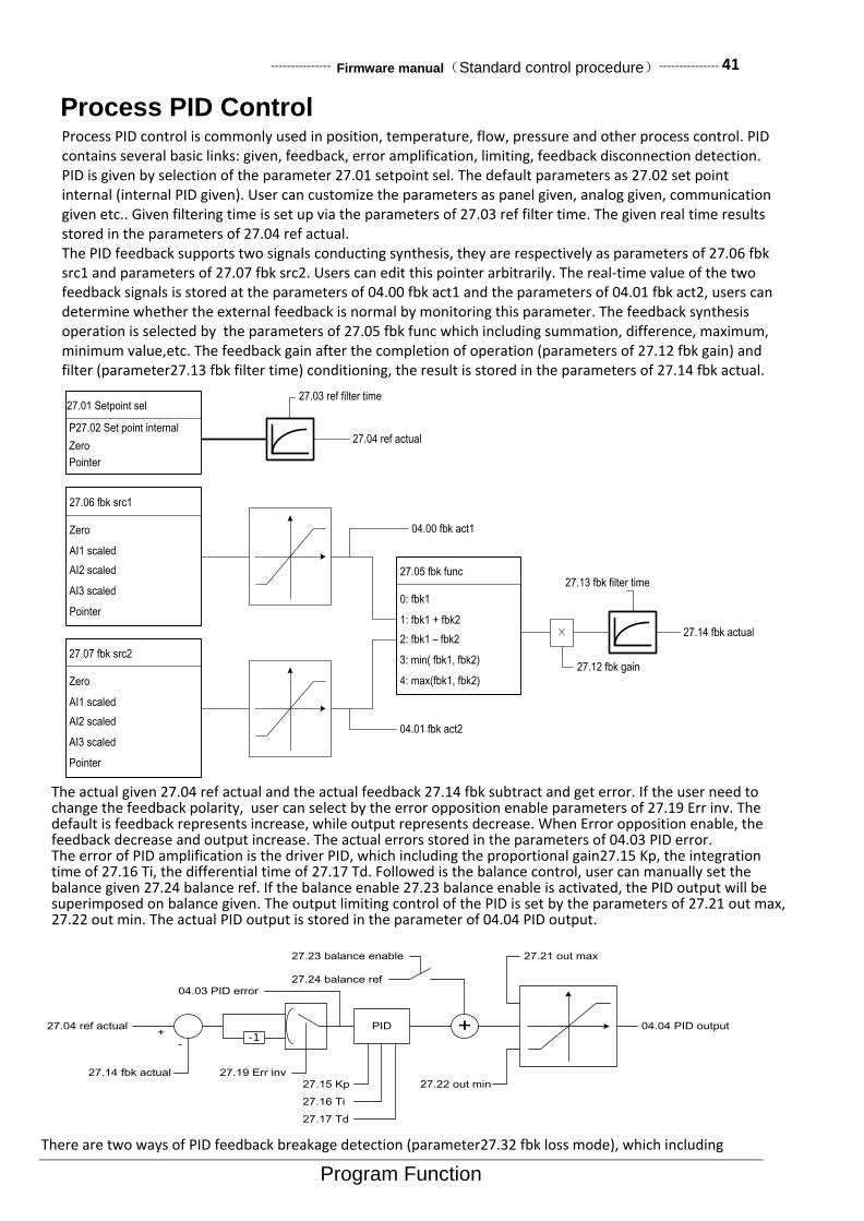
--------------- Firmware manual(Standard control procedure)--------------- 41
Program Function
Process PID Control Process PID control is commonly used in position, temperature, flow, pressure and other process control. PID contains several basic links: given, feedback, error amplification, limiting, feedback disconnection detection. PID is given by selection of the parameter 27.01 setpoint sel. The default parameters as 27.02 set point internal (internal PID given). User can customize the parameters as panel given, analog given, communication given etc.. Given filtering time is set up via the parameters of 27.03 ref filter time. The given real time results stored in the parameters of 27.04 ref actual. The PID feedback supports two signals conducting synthesis, they are respectively as parameters of 27.06 fbk src1 and parameters of 27.07 fbk src2. Users can edit this pointer arbitrarily. The real-time value of the two feedback signals is stored at the parameters of 04.00 fbk act1 and the parameters of 04.01 fbk act2, users can determine whether the external feedback is normal by monitoring this parameter. The feedback synthesis operation is selected by the parameters of 27.05 fbk func which including summation, difference, maximum, minimum value,etc. The feedback gain after the completion of operation (parameters of 27.12 fbk gain) and filter (parameter27.13 fbk filter time) conditioning, the result is stored in the parameters of 27.14 fbk actual.
27.01 Setpoint sel
P27.02 Set point internal
Zero
Pointer
27.06 fbk src1
Zero
AI1 scaled
AI2 scaled
AI3 scaled
Pointer
27.07 fbk src2
Zero
AI1 scaled
AI2 scaled
AI3 scaled
Pointer
27.05 fbk func
0: fbk1
1: fbk1 + fbk2
2: fbk1 – fbk2
3: min( fbk1, fbk2)
4: max(fbk1, fbk2)
27.03 ref filter time
27.13 fbk filter time
27.04 ref actual
27.14 fbk actual×
27.12 fbk gain
04.00 fbk act1
04.01 fbk act2
The actual given 27.04 ref actual and the actual feedback 27.14 fbk subtract and get error. If the user need to change the feedback polarity, user can select by the error opposition enable parameters of 27.19 Err inv. The default is feedback represents increase, while output represents decrease. When Error opposition enable, the feedback decrease and output increase. The actual errors stored in the parameters of 04.03 PID error. The error of PID amplification is the driver PID, which including the proportional gain27.15 Kp, the integration time of 27.16 Ti, the differential time of 27.17 Td. Followed is the balance control, user can manually set the balance given 27.24 balance ref. If the balance enable 27.23 balance enable is activated, the PID output will be superimposed on balance given. The output limiting control of the PID is set by the parameters of 27.21 out max, 27.22 out min. The actual PID output is stored in the parameter of 04.04 PID output.
27.04 ref actual
27.14 fbk actual
+
--1
27.19 Err inv
PID
27.17 Td
27.16 Ti
27.15 Kp
+
27.24 balance ref
04.04 PID output
27.23 balance enable
27.22 out min
27.21 out max
04.03 PID error
There are two ways of PID feedback breakage detection (parameter27.32 fbk loss mode), which including

42--------------- Firmware manual(Standard control procedure)---------------
Program Function
external breakage input (parameter27.34 fbk loss DI) and internal error comparison (parameter27.35 fbk loss level). Feedback breakage only effect when the motor speed is greater than the minimum speed 27.33 fbk loss min spd. When the feedback breakage is detected, the feedback breakage fault will be sent out after the delay of 27.36 fbk loss dly.
27.32 fbk loss mode
27.34 fbk loss DI
Fbk Fault
27.36 Fbk loss dly
27.33 Fbk loss min spd <= Speed actual+
-
04.03 PID error
27.35 fbk loss level
Motor Control
Compared with other brands in the market, the ES Series drive almost don’t need to adjust the parameters in motor control. Parameters related to motor control refer to the parameter group 60 Motor control. Carrier frequency settings refer to 60.00 carrier freq set. The default values of different models are different. When the motor line is longer (About 100m or above) , please reduce the carrier frequency to avoid excessive reflection voltage of the motor. Slip gain refer to 60.01 slip gain. The speed estimation error of the open-loop control can be improved by adjusting the parameters. Under closed loop control, the parameter can improve the excitation of the motor so as to achieve the best torque output of the motor. Shock suppression 60.04 Res damp gain, used for open-loop control only. The smaller the inertia has, the more likely to shock the motor. Rotation speed tracking refer to the parameter of 60.06 fly restart, used for open-loop control only. Users can activate to use. Overvoltage stall refer to the parameters of 60.07 Vdc max control, default enable. If need to use the brake resistor, please turn off this function. Undervoltage stall refer to the parameters of 60.08 Vdc min control, default prohibited. Auto-tuning refer to the parameters of 63.06 ID run request. It can support static tuning and rotation tuning. Configuration of the encoder refers to the parameter group 61 Encoder config. The status of the encoder option card refers to the parameters of 09.03 Encoder type.
Motor Thermal Protection The core of the motor thermal protection is to obtain the temperature of the motor, with the ways of sensor detection and thermal model estimation. Three kinds of the supported temperature sensor types are KTY84, PT100, PTC. The wiring of the temperature sensor is shown as below (Taking AI2, AO2 as an example). AO used for the current output bias so that the temperature sensor produces voltage signal, while AI2 used for detecing the voltage signal of the sensor.
Different types of sensor has different bias current, with the purpose to maintain the appropriate output voltage. The input current of PT100 is 10mA, of PTC and KTY84 is 2mA. The bias current source channel selection is determined by the parameter of 31.12 Bias sel, user can choose either AO1 or AO2. When the type of temperature detection (parameter 31.01 Mot temp src) is not 0 (temperature estimation), the bias current source will be enabled. The actual temperature can be measured directly for PT100 and KTY84; while for PTC, since it is a nonlinear device, only the overheat protection can be executed, the motor temperature can not be measured accurately. If not connected with the sensor, the default system will use the way of thermal model estimation to obtain the temperature of the motor.
Bias current
source,AO
Force for
simulation mode
0: AO1
1: AO2
31.12 Bias sel
KTY84: 2.0mA
PTC: 2.0mA
PT100: 10.0mA
Other invalid
AO2
AI2
GND
Temperature
sensor
There are three kinds of motor thermal protection action: no action, warning, fault. Refer to the parameter of 31.00 Motor over heat action. Warning temperature point refer to the parameter of 31.02 Alarm limit, fault temperature point refer to the parameter of 31.03 Fault limit. As for the PTC sensor, warning when the voltage is greater than 4.0V, fault trip when greater than 8.0V.
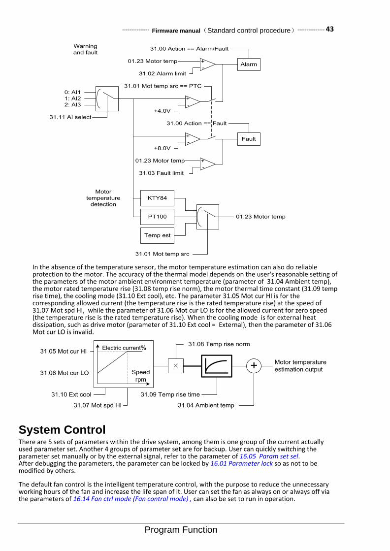
--------------- Firmware manual(Standard control procedure)--------------- 43
Program Function
Warning
and fault
31.11 AI select
0: AI1
1: AI2
2: AI3+
-+4.0V
31.02 Alarm limit
+
-
01.23 Motor tempAlarm
31.01 Mot temp src == PTC
+
-+8.0V
Fault
31.03 Fault limit
+
-
01.23 Motor temp
31.00 Action == Alarm/Fault
31.00 Action == Fault
Temp est
KTY84
PT100
31.01 Mot temp src
01.23 Motor temp
Motor
temperature
detection
In the absence of the temperature sensor, the motor temperature estimation can also do reliable protection to the motor. The accuracy of the thermal model depends on the user's reasonable setting of the parameters of the motor ambient environment temperature (parameter of 31.04 Ambient temp), the motor rated temperature rise (31.08 temp rise norm), the motor thermal time constant (31.09 temp rise time), the cooling mode (31.10 Ext cool), etc. The parameter 31.05 Mot cur HI is for the corresponding allowed current (the temperature rise is the rated temperature rise) at the speed of 31.07 Mot spd HI, while the parameter of 31.06 Mot cur LO is for the allowed current for zero speed (the temperature rise is the rated temperature rise). When the cooling mode is for external heat dissipation, such as drive motor (parameter of 31.10 Ext cool = External), then the parameter of 31.06 Mot cur LO is invalid.
Speed
rpm
Electric current% 31.05 Mot cur HI
31.06 Mot cur LO
31.07 Mot spd HI
31.10 Ext cool
×
31.08 Temp rise norm
31.09 Temp rise time
Motor temperature
estimation output+
31.04 Ambient temp
System Control There are 5 sets of parameters within the drive system, among them is one group of the current actually used parameter set. Another 4 groups of parameter set are for backup. User can quickly switching the parameter set manually or by the external signal, refer to the parameter of 16.05 Param set sel. After debugging the parameters, the parameter can be locked by 16.01 Parameter lock so as not to be modified by others.
The default fan control is the intelligent temperature control, with the purpose to reduce the unnecessary working hours of the fan and increase the life span of it. User can set the fan as always on or always off via the parameters of 16.14 Fan ctrl mode (Fan control mode) , can also be set to run in operation.
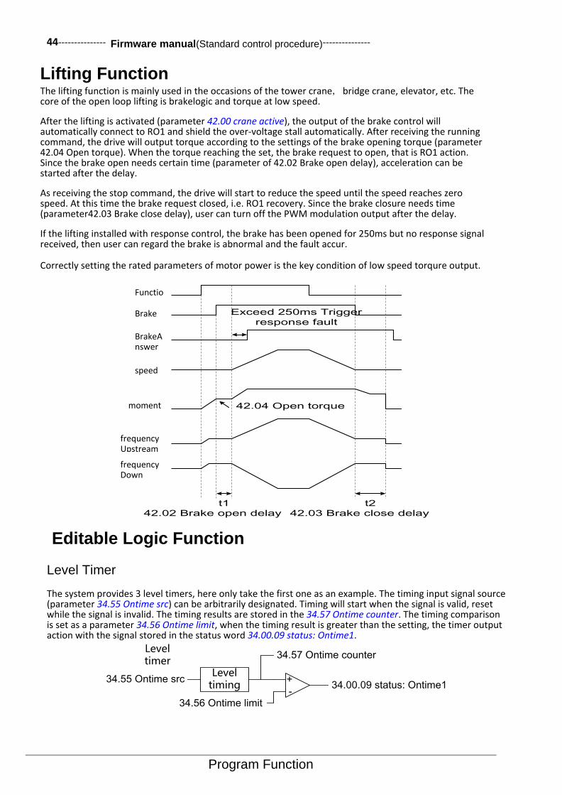
44--------------- Firmware manual(Standard control procedure)---------------
Program Function
Lifting Function The lifting function is mainly used in the occasions of the tower crane, bridge crane, elevator, etc. The core of the open loop lifting is brakelogic and torque at low speed.
After the lifting is activated (parameter 42.00 crane active), the output of the brake control will automatically connect to RO1 and shield the over-voltage stall automatically. After receiving the running command, the drive will output torque according to the settings of the brake opening torque (parameter 42.04 Open torque). When the torque reaching the set, the brake request to open, that is RO1 action. Since the brake open needs certain time (parameter of 42.02 Brake open delay), acceleration can be started after the delay.
As receiving the stop command, the drive will start to reduce the speed until the speed reaches zero speed. At this time the brake request closed, i.e. RO1 recovery. Since the brake closure needs time (parameter42.03 Brake close delay), user can turn off the PWM modulation output after the delay.
If the lifting installed with response control, the brake has been opened for 250ms but no response signal received, then user can regard the brake is abnormal and the fault accur.
Correctly setting the rated parameters of motor power is the key condition of low speed torqure output.
Functi
on
抱闸
速度
力矩
频率
上行
频率
下行
t1 t2
42.04 Open torque
42.03 Brake close delay42.02 Brake open delay
抱闸
应答
Exceed 250ms Trigger
response fault
Editable Logic Function
Level Timer
The system provides 3 level timers, here only take the first one as an example. The timing input signal source (parameter 34.55 Ontime src) can be arbitrarily designated. Timing will start when the signal is valid, reset while the signal is invalid. The timing results are stored in the 34.57 Ontime counter. The timing comparison is set as a parameter 34.56 Ontime limit, when the timing result is greater than the setting, the timer output action with the signal stored in the status word 34.00.09 status: Ontime1.
34.55 Ontime src
34.56 Ontime limit
Level timing
+
-
34.57 Ontime counter
34.00.09 status: Ontime1
Level timer
Functio
n Brake
BrakeAnswer
speed
moment
frequencyUpstream
frequencyDown

--------------- Firmware manual(Standard control procedure)--------------- 45
Program Function
Edge Counter
There are 3 edge counters, here only take the first counter as an example, the rest is similar. User can specify any input signal source (parameter 34.02 edge1 src) . The counting mode (parameter34.04 edge1 type) can be a rising edge, a falling edge or both detection. The reset mode of the counter can choose the external reset signal (34.03 edge1 rst), can also achieve the automatic reset by the internal maximum count value (parameters of 34.07 edge1 autoreset, 34.06 edge1 max). The real-time counting results of the counter stored in the parameters of 34.01 edge1 counter. When the counter reach to the set point (parameter 34.05 edge1 cmp), the status word 34.00.00 status:edge1 is 1, otherwise is 0. User can point to the status bit in other modules by the bit pointer.
Along counter
34.02 edge1 srcCounter1
34.01 edge1 counter
34.04 edge1 type
34.03 edge1 rst
34.05 edge1 cmp
+
-34.00.00 status: edge1
+
-
34.06 edge1 max
34.07 edge1 auto reset
Comparator
The system provides 3 general comparatorus, here only take the comparator1 as an example. The signal source used for comparison (parameter34.23 cmp1 src) can be set arbitrarily with the pointer. The comparison method can be an amplitude comparison, can also be a symbolic comparison, refering to the parameter of 34.26 cmp1 abs. The comparison point is set as the parameterof 34.24 cmp1 set. The comparison types refer to the parameters of 34.28 cmp1 win enable. In general comparison status, the hysteresis band of the comparison refer to the parameters of 34.25 cmp1 hyst; while in the window comparison status, the window width as parameter 34.25 cmp1 hyst. The logic polarity of comparison can be selected by the parameter of 34.28 cmp1 inv. The output status of the comparator is stored in the status word 34.00.03 status:cmp1.
comparator
34.23 cmp1 src
|x|
34.26 cmp1 abs
+
-34.24 cmp1 set
34.25 cmp1 hyst
34.28 cmp1 win en
34.28 cmp1 inv
34.00.03 status: cmp1
Logic Arithmetic Unit
The system provides 3 general logic arithmetic units, here only take the first one as an example. The logic operator contains three input signal sources (parameter 34.43 Logic in A, 34.44 Logic in B, 34.45 Logic in C). There are 6 kinds of logical operator type (parameter34.46 Logic oper), respectively as AND, OR, WRONG, EXCLUSIVE OR, REVERSE, AND NON. The operation output is stored in the status word 34.00.06 status: logic1.

46--------------- Firmware manual(Standard control procedure)---------------
Program Function
Logic arithmetic
unit
34.43 Logic in A
34.44 Logic in B
34.45 Logic in C
A & B & C
A | B | C
~A
A ^ B
Toggle by A
~(A & B & C)
34.46 Logic oper
34.00.06 status: logic1
Programmable Arithmetic Function
Process Variable Conversion The process control quantity conversion is used to convert the process quantity into the dimension required by the user. The system provides 3 general process control volume conversions, here only take the first one as an example. The input of the process conversion can be selected by 35.00 PrcsVar1 src. If only convert the size of the amplitude, then enable the absolute value of the operation (parameter 35.06 PrcsVar1 abs). The mapping of the conversion input to output is set by the parameters from 35.02 PrcsVar1 src max to 35.05 PrcsVar1 out min. The conversion results stored in the parameters of 35.01 PrcsVar1 out. The units and the decimal points of the conversion results in the panel display can be specified by the parameter of 35.07 Linear1 y dec and the parameter of 35.08 Linear1 y unit.
Process variable
conversion
35.00 PrcsVar1 src
|x|
35.06 PrcsVar1 abs
35.05 PrcsVar1 out min
35.04 PrcsVar1 out max
Scale
35.01 PrcsVar1 out
35.02 PrcsVar1 src max
35.03 PrcsVar1 src min
Basic Arithmetic Operation The system provides 3 general basic arithmetic units, here only take the first one as an example. The
arithmetic unit 1 contains a plurality of input signal sources (parameter of 35.27 Math1 src1, 35.28 Math
src2). The type of operation (parameter of 35.29 Math1 oper) including the plus, minus, minimum,
maximum, absolute value, multiply, devide. For the operation of multiplication and division, user needs to
develop a reference value N (parameter35.30 Math1 scale). The output of the operation is stored in the
35.31 Math1 out. Users can point to it by the pointer.

--------------- Firmware manual(Standard control procedure)--------------- 47
Program Function
Basic arithmetic operation
35.27 Math1 src1
35.28 Math1 src2
A + B
A - B
Min(A, B)
Max(A, B)
|A|
A * B / N
35.30 Math1 scale
A / B * N
35.29 Math1 oper
35.31 Math1 out
Universal Filter The system provides 3 general first-order low-pass filter, here only take the first one as an example. The
input signal source of the filter can be set via the parameters of 35.51 filter src1. The filtering time of the
filter can be set via the parameters of 35.53 filter1 time. The output of the filter is stored in the35.52
filter1 out.
35.51 filter1 src1
35.53 filter1 time
35.52 filter1 out
First order low pass filter
Integrator The system provides 3 general integrators which are used to count the integral quantity of the
displacement, the flow, etc., here only take the first integrator as an example. The input signal source of
the integrator can be set by the parameter of 35.42 intgrt1 src, the conversion unit of the integrator set
by 35.44 intgrt1 scale. The integrator output parameters stored in the35.43 intgrt1 out.
35.42 intgrt1 src
35.44 intgrt1 scale
35.43 intgrt1 out
integrator
integrator
Fault Warning Programming The drive fault can be classified as maskable and non-maskable. For the fatal fault, the system does not
allow the user to shield it. For the peripheral soft faults, user can choose a warning or the fault output.
The maskable faults are: earth leakage fault, input / output phase failure, overheating warning, braking
IGBT fault, braking resistance fault.
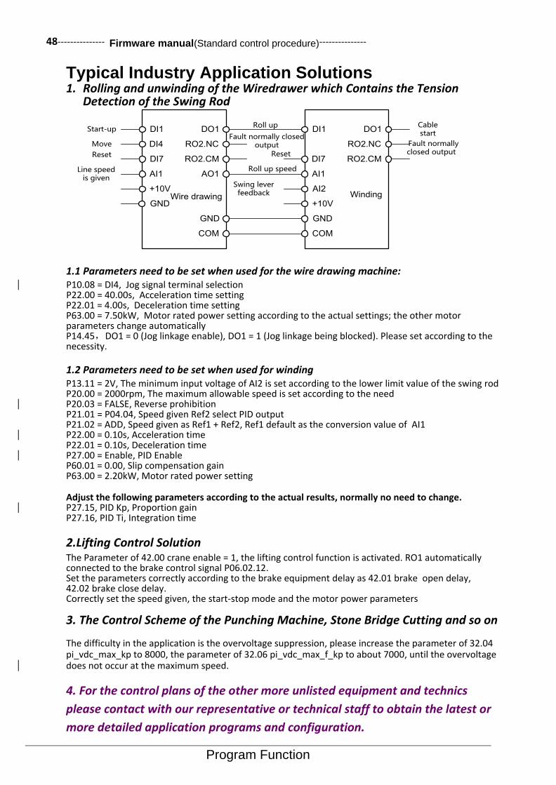
48--------------- Firmware manual(Standard control procedure)---------------
Program Function
Typical Industry Application Solutions 1. Rolling and unwinding of the Wiredrawer which Contains the Tension
Detection of the Swing Rod
DI1
DI4
DI7
AI1
Start-up
Move
Reset
Line speed is given
Wire drawing
DO1Roll up
RO2.NCFault normally closed
output
RO2.CM
AO1Roll up speed
DI1
DI7
AI2
AI1
DO1Cable start
RO2.NC Fault normally closed output
RO2.CMReset
Swing lever feedback
GND GND
COM COM
+10VWinding
GND
+10V
1.1 Parameters need to be set when used for the wire drawing machine: P10.08 = DI4, Jog signal terminal selection P22.00 = 40.00s, Acceleration time setting P22.01 = 4.00s, Deceleration time setting P63.00 = 7.50kW, Motor rated power setting according to the actual settings; the other motor parameters change automatically P14.45,DO1 = 0 (Jog linkage enable), DO1 = 1 (Jog linkage being blocked). Please set according to the necessity.
1.2 Parameters need to be set when used for winding P13.11 = 2V, The minimum input voltage of AI2 is set according to the lower limit value of the swing rod P20.00 = 2000rpm, The maximum allowable speed is set according to the need P20.03 = FALSE, Reverse prohibition P21.01 = P04.04, Speed given Ref2 select PID output P21.02 = ADD, Speed given as Ref1 + Ref2, Ref1 default as the conversion value of AI1 P22.00 = 0.10s, Acceleration time P22.01 = 0.10s, Deceleration time P27.00 = Enable, PID Enable P60.01 = 0.00, Slip compensation gain P63.00 = 2.20kW, Motor rated power setting
Adjust the following parameters according to the actual results, normally no need to change. P27.15, PID Kp, Proportion gain P27.16, PID Ti, Integration time
2.Lifting Control Solution The Parameter of 42.00 crane enable = 1, the lifting control function is activated. RO1 automatically connected to the brake control signal P06.02.12. Set the parameters correctly according to the brake equipment delay as 42.01 brake open delay, 42.02 brake close delay. Correctly set the speed given, the start-stop mode and the motor power parameters
3. The Control Scheme of the Punching Machine, Stone Bridge Cutting and so on
The difficulty in the application is the overvoltage suppression, please increase the parameter of 32.04 pi_vdc_max_kp to 8000, the parameter of 32.06 pi_vdc_max_f_kp to about 7000, until the overvoltage does not occur at the maximum speed.
4. For the control plans of the other more unlisted equipment and technics
please contact with our representative or technical staff to obtain the latest or
more detailed application programs and configuration.

--------------- Firmware manual(Standard control procedure)--------------- 49
Parameters
5. Drive Parameters list This chapter describes the parameters of the control program, including the actual signal.
Parameter Iist Instruction
1: Literal description of the enumeration type parameter ( the first column of the table) solidified on LCD control keyboard. When using the MODBUS communication and the field bus edit parameters, please write this parameter with corresponding value (the third column of the table) of the specified text description.
2:The default option list of the pointer type parameters provides only a number of commonly used signal sources. If the user want to select another signal source, select the first option when using the control keyboard to edit the pointer parameters (LCD show as P.xx.yy.zz, xx indicates the group number, yy indicates the index, zz indicates the item (Numeric pointer does not have this part). The specific value is determined by the current value of the parameter, then enter the pointer edit mode to select the parameters corresponding to the specified signal (the bit pointer also need to specify a specific binary bit), or use the MODBUS communications and the fieldbus to make the specified sigal corresponding parameters of the pointer code (refer to the relevant content of the "parameter" section of the "LCD control keyboard" chapter to learn the pointer encoding format) and write into this parameter.
01 Actual values
01Actual values Basic Signal of the Drive Monitoring unit
01.00 Motor speed
The unit of the filtered motor speed is rpm. In open loop control, real time rpm for motor estimation; in closed loop control, measured real time speed for motor encoder.
0.1rpm
01.01 Output frequency
Actual value of drive output frequency, Unit isHz. 0.1Hz
01.02 DC bus voltage
Intermediate circuit voltage measurement, Unit is V. 0.1V
01.03 Motor current
Motor current measurement, Unit is A. 0.1A
01.04 Motor current%
Motor current expressed as percentage of motor
rated current. 0.1%
01.05 Heat sink temp
Measured radiator temperature. 0.1℃
01.06 Rectifier temp
For F6 models, indicates the measured temperature of radiator where the rectifier bridge is located. Other models are the same as 01.05 (radiator structure of the rectifier and the inverter).
。
0.1℃
01.07 CPU temperature
Measured temperature of CPU. 0.1℃
01.08 IGBT Tjc
Temperature difference between the IGBT chip and
the copper substrate. 0.1℃
01.09 IGBT Tj
IGBT Chip temperature. 0.1℃
01.10 IGBT power loss
IGBT Loss power. 0.001kW
01.11 CPU usage
CPU Actual loading rate. 0.1%
01.12 Motor slip est
Estimated value of the motor slip frequency, Unit is
Hz. 0.01Hz
01.13 Motor flux est
The estimated value of the motor flux, relative o the
rated flux, Unit is %. 0.1%
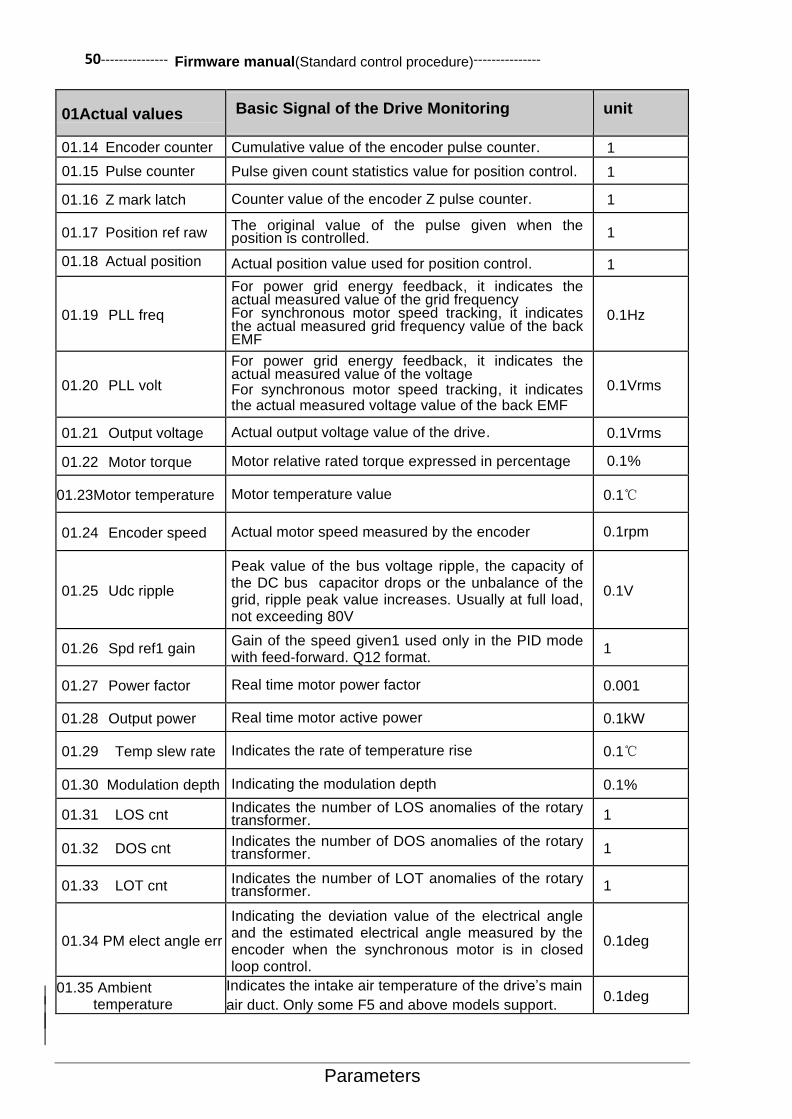
50--------------- Firmware manual(Standard control procedure)---------------
Parameters
01Actual values Basic Signal of the Drive Monitoring unit
01.14 Encoder counter
Cumulative value of the encoder pulse counter. 1
01.15 Pulse counter Pulse given count statistics value for position control. 1
01.16 Z mark latch Counter value of the encoder Z pulse counter. 1
01.17 Position ref raw The original value of the pulse given when the position is controlled. 1
01.18 Actual position
Actual position value used for position control. 1
01.19 PLL freq
For power grid energy feedback, it indicates the actual measured value of the grid frequency For synchronous motor speed tracking, it indicates the actual measured grid frequency value of the back EMF
0.1Hz
01.20 PLL volt
For power grid energy feedback, it indicates the actual measured value of the voltage For synchronous motor speed tracking, it indicates the actual measured voltage value of the back EMF
0.1Vrms
01.21 Output voltage Actual output voltage value of the drive. 0.1Vrms
01.22 Motor torque Motor relative rated torque expressed in percentage 0.1%
01.23 Motor temperature Motor temperature value 0.1℃
01.24 Encoder speed Actual motor speed measured by the encoder 0.1rpm
01.25 Udc ripple
Peak value of the bus voltage ripple, the capacity of the DC bus capacitor drops or the unbalance of the grid, ripple peak value increases. Usually at full load, not exceeding 80V
0.1V
01.26 Spd ref1 gain Gain of the speed given1 used only in the PID mode with feed-forward. Q12 format.
1
01.27 Power factor Real time motor power factor 0.001
01.28 Output power Real time motor active power 0.1kW
01.29 Temp slew rate Indicates the rate of temperature rise 0.1℃
01.30 Modulation depth Indicating the modulation depth 0.1%
01.31 LOS cnt Indicates the number of LOS anomalies of the rotary transformer. 1
01.32 DOS cnt Indicates the number of DOS anomalies of the rotary transformer. 1
01.33 LOT cnt Indicates the number of LOT anomalies of the rotary transformer. 1
01.34 PM elect angle err
Indicating the deviation value of the electrical angle and the estimated electrical angle measured by the encoder when the synchronous motor is in closed loop control.
0.1deg
01.35 Ambient temperature
Indicates the intake air temperature of the drive’s main
air duct. Only some F5 and above models support. 0.1deg

--------------- Firmware manual(Standard control procedure)--------------- 51
Parameters
02 I/O Values
02 I/O values Input and output signals Unit
02.00 DI status
From the right to the left are the status of the digital input DI1, DI2, …… , DI7. For instance: 0000001=DI1 is 1, DI2…DI7 is 0. For the meaning of 0 and 1, refer to the parameters of 14.22 DI logic (DI Input logic).
-
02.01 DO status
From the right to the left are the status of the digital output DO1, DO2 and the relay output RO1, RO2 . For instance: 0101 =DO1synizesis, DO2 Disconnection, RO1 Already electrified, RO2 Power off. For the meaning of synizesis and disconnection, refer to the parameters of 14.26 DO logic (DO Output logic).
-
02.02 AI1 actual The actual value of the analog input AI1. Unit is V. 0.001V
02.03 AI1 scaled
The conversion value of the analog input AI1. Refer to the
parameters 13.05 AI1 max scale (AI1 conversion maximum)
and 13.06 AI1 min scale (AI1 conversion minimum).
-
02.04 AI2 actual The actual value of the analog input AI2. Unit is V or mA.
Set by the parameter of 13.17 AI2 input type (AI2 Input type).
0.001V or 0.001mA
02.05 AI2 scaled
The conversion value of the analog input AI2. Refer to the
parameters 13.15 AI2 max scale (AI2 conversion maximum)
and 13.16 AI2 min scale (AI2 conversion minimum).
-
02.06 AI3 actual The actual value of the analog input AI3. Unit isV or mA. Set by the of parameter 13.28 AI3 input type (AI3 Input type).
0.001V or 0.001mA
02.07 AI3 scaled
The conversion value of the analog input AI3. Refer to the
parameters 13.26 AI3 max scale (AI3 conversion maximum)
and 13.27 AI3 min scale (AI3 conversion minimum).
-
02.08 AO1 actual The actual value of the analog output AO1. Unit is V or mA. Set by the parameter 15.08 AO1 output type (AO1 Output type).
0.001V or 0.001mA
02.09 AO2 actual The actual value of the analog output AO2. Unit is V or mA. Set by the parameter 15.18 AO2 output type (AO2 Output type).
0.001Vor0.001mA
02.10 Freq in actual
The actual frequency of DI7 high speed pulse input. 1Hz
02.11 Freq in scaled The conversion value of DI7 high speed pulse input. -
02.12 Freq out actual The actual output frequency of DO2 after enabling the DO2 frequency output function. 1Hz
02.13 Control panel ref1
Given1 of the control keyboard. 1rpm
02.14 Control panel ref2
Given2 of the control keyboard. 0.1%
02.15 Fieldbus ref1 Given value1 of the field bus. 1rpm
02.16 Fieldbus ref2 Given value2 of the field bus. 0.1%
02.17 Speed ffwd
Speed feedforward given value of the pulse train control. 1 rpm

52--------------- Firmware manual(Standard control procedure)---------------
Parameters
03 Control Values
03 Control values Speed control, torque control and other values
Unit
03.00 Speed ref output The output value of speed given module. 1rpm
03.01 Motor potent out
The speed given value of the digital potentiometer, can
be achieved by the terminal for the addition and
substraction of the speed given.
1rpm
03.02 Const speed out The output given value for the multi segment speed
function module. 1rpm
03.03 Speed ref unramp Use the speed given value before the ramp and the
forming speed. 1rpm
03.04 Speed ref ramped Ramp and forming speed given. 1rpm
03.05 Control mode used Actually implemented control mode. -
03.06 Torque ref unramp The value of the torque given before the ramp input is
the percentage of the relative maximum torque. 0.1%
03.07 Torque ref ramped Ramp torque given value, As percentage. 0.1%

--------------- Firmware manual(Standard control procedure)--------------- 53
Parameters
04 App values
04 App values Process and Counter Values Unit
04.00 Process act1 Process feedback1 of the process PID controller. -
04.01 Process act2 Process feedback2 of the process PID controller. -
04.02 Process act Final process feedback for process feedback
selection and modification. -
04.03 Process PID err Process PID deviation value, that is, the difference
value between the PID set point and the feedback. -
04.04 Process PID out Output of the process PID controller. -
04.05 Line spd act Actual value of the winding control line speed. 0.1m/min
04.06 Trq out Nm Torque control volume of the winding control. Unit
is Nm. 0.1Nm
04.07 Trq out percent The torque control quantity of the winding control.
Unit is %. 0.1%
04.08 Tense ref Tension given value of the winding control. 0.1N
04.09 Tense ref taped Tension given value of the corrected tension taper. 0.1N
04.10 Roll dia est Roller diameter estimated value of the winding
control. 1mm
04.11 Pulse counter The external circles of signal count value used for
measuring the roller diameter . 1
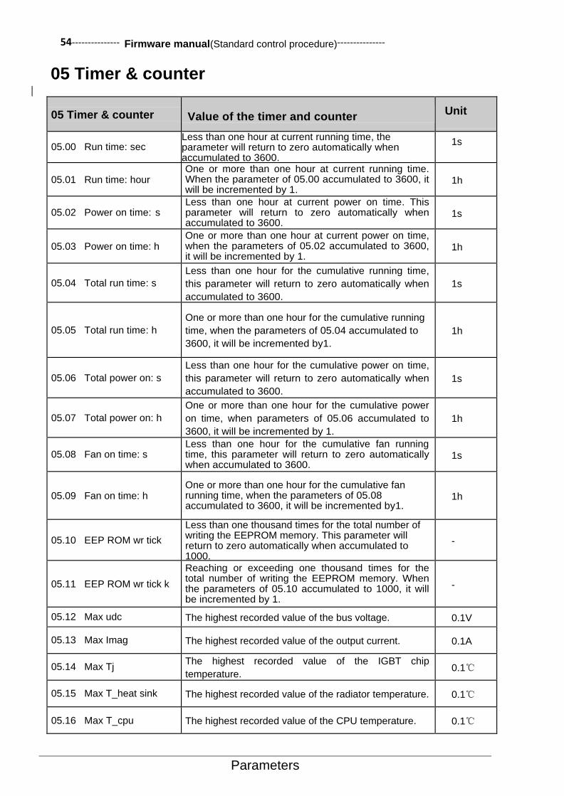
54--------------- Firmware manual(Standard control procedure)---------------
Parameters
05 Timer & counter
05 Timer & counter Value of the timer and counter Unit
05.00 Run time: sec Less than one hour at current running time, the parameter will return to zero automatically when accumulated to 3600.
1s
05.01 Run time: hour One or more than one hour at current running time. When the parameter of 05.00 accumulated to 3600, it will be incremented by 1.
1h
05.02 Power on time: s Less than one hour at current power on time. This parameter will return to zero automatically when accumulated to 3600.
1s
05.03 Power on time: h One or more than one hour at current power on time, when the parameters of 05.02 accumulated to 3600, it will be incremented by 1.
1h
05.04 Total run time: s
Less than one hour for the cumulative running time,
this parameter will return to zero automatically when
accumulated to 3600.
1s
05.05 Total run time: h
One or more than one hour for the cumulative running
time, when the parameters of 05.04 accumulated to
3600, it will be incremented by1.
1h
05.06 Total power on: s
Less than one hour for the cumulative power on time,
this parameter will return to zero automatically when
accumulated to 3600.
1s
05.07 Total power on: h
One or more than one hour for the cumulative power
on time, when parameters of 05.06 accumulated to
3600, it will be incremented by 1.
1h
05.08 Fan on time: s Less than one hour for the cumulative fan running time, this parameter will return to zero automatically when accumulated to 3600.
1s
05.09 Fan on time: h One or more than one hour for the cumulative fan running time, when the parameters of 05.08 accumulated to 3600, it will be incremented by1.
1h
05.10 EEP ROM wr tick
Less than one thousand times for the total number of writing the EEPROM memory. This parameter will return to zero automatically when accumulated to 1000.
-
05.11 EEP ROM wr tick k
Reaching or exceeding one thousand times for the total number of writing the EEPROM memory. When the parameters of 05.10 accumulated to 1000, it will be incremented by 1.
-
05.12 Max udc The highest recorded value of the bus voltage. 0.1V
05.13 Max Imag The highest recorded value of the output current. 0.1A
05.14 Max Tj The highest recorded value of the IGBT chip
temperature. 0.1℃
05.15 Max T_heat sink The highest recorded value of the radiator temperature. 0.1℃
05.16 Max T_cpu The highest recorded value of the CPU temperature. 0.1℃
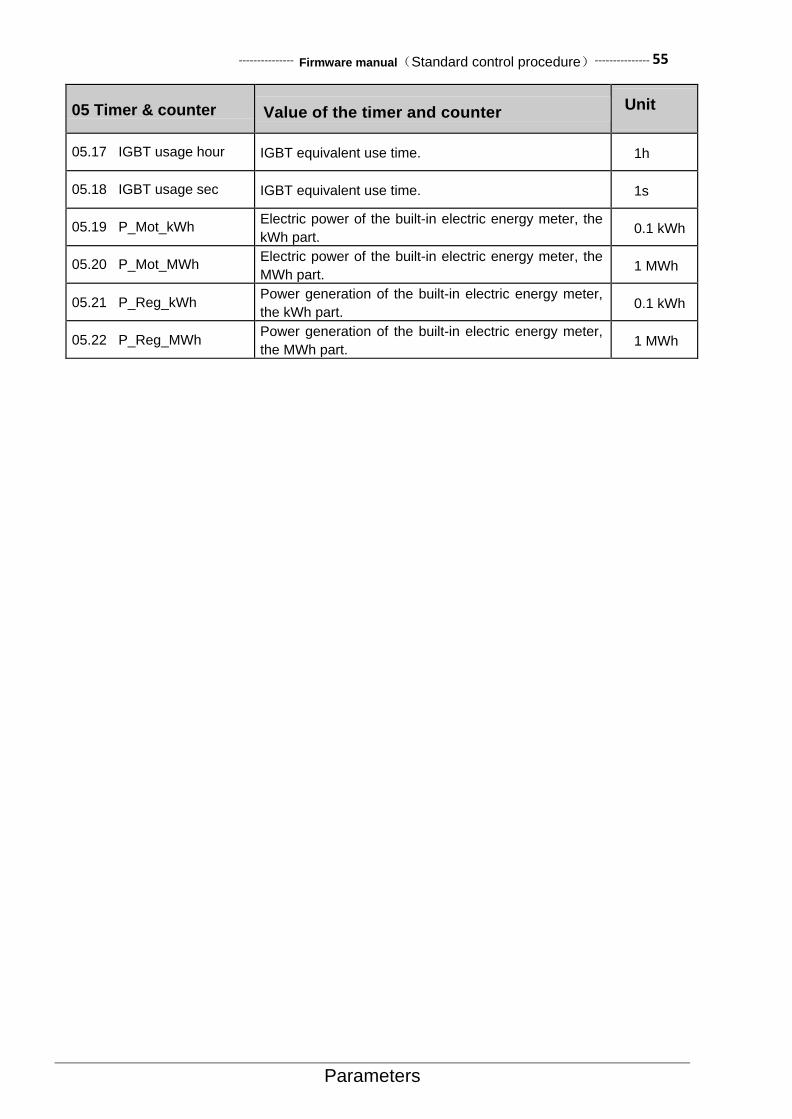
--------------- Firmware manual(Standard control procedure)--------------- 55
Parameters
05 Timer & counter Value of the timer and counter Unit
05.17 IGBT usage hour IGBT equivalent use time. 1h
05.18 IGBT usage sec IGBT equivalent use time. 1s
05.19 P_Mot_kWh Electric power of the built-in electric energy meter, the
kWh part. 0.1 kWh
05.20 P_Mot_MWh Electric power of the built-in electric energy meter, the
MWh part. 1 MWh
05.21 P_Reg_kWh Power generation of the built-in electric energy meter,
the kWh part. 0.1 kWh
05.22 P_Reg_MWh Power generation of the built-in electric energy meter,
the MWh part. 1 MWh

56--------------- Firmware manual(Standard control procedure)---------------
Parameters
06 Drive Status 06 Drive status Drive status word
Serial number Name /Value
Description FbEq 06.00 Status word1
Drive status word1 .
position Name Information
0 Ready 1=Drive ready to receive start command.
0=Drive not ready.
1 Fault 1=Drive fault.
0=Drive no fault.
2 Alarm 1=Drive warning.
0=Drive no warning.
3 Limiting 1=Drive limited.
0= Drive unlimited.
4 Running 1= Drive running.
0=Drive not running.
5 Rev req 1=Drive starting reversal.
0=Drive starting forward.
6 Start req 1=Driver received Start request.
0=Drive not received Start request.
7 Stop req 1=Drive received shutdown request
0=Drive not received shutdown request.
8 JOG active 1=Drive jog operation.
0=Drive jog function not activated.
9 Int stop req 1=Drive internal forced shutdown activated.
0=Drive forced shutdown function not activated.
10 Ext run enable
1=Drive external operation enabled.
0=Drive external operation not enabled.
11 JOG2 1=Drive JOG2 activated.
0= Drive JOG1 activated.
12 DC charged
1=DC high voltage capacitor charging completed. 0=DC high voltage capacitor charging not completed.
13 Chg rly closed
1=Soft start relay closure.
0=Soft start relay disconnect.
14 Ext2 1=Control place2 activated.
0=Control place1activated.
15 Loc ctrl 1=Drive operates in remote control mode.
0=Drive operates in the local control mode.
-

--------------- Firmware manual(Standard control procedure)--------------- 57
Parameters
06 Drive status Drive status word
06.01 Status word2
Drive status word2
position Name Information
0 Data log rdy
1=Software oscilloscope waveform cache updated. 0=Software oscilloscope waveform cache not updated.
1 OFF1 1=OFF1 (Deceleration stop) activated.
0=OFF1 (Deceleration stop) not activated.
2 OFF2
1=OFF2 (Emergency stop coast stop) activated. 0=OFF2 (Emergency stop coast stop) not activated.
3 OFF3
1=OFF3 (Emergency stop deceleration stop) activated. 0=OFF3 (Emergency stop deceleration stop) not activated.
4 Motor Brk 1= activated.
0= not activated.
5 Ramp in zero 1=Ramp input forced to zero.
0=Normal operation.
6 Ramp out zero 1= Ramp output forced to zero.
0=Normal operation.
7 Ramp hold 1=Ramp input forced to keep.
0= Normal operation.
8 Modulating 1= Modulating, IGBT being controlled.
0=No modulating, IGBT not being controlled.
9 Modbus active
1=Built-in MODBUS Communication activated. 0=Built-in MODBUS Communication not activated.
10 CANopen active
1=Built-in CAN Communication activated.
0=Built-inCAN Communication not activated.
11 Profi-DP active
1=PROFIBUS-DP Communication activated. 0=PROFIBUS-DP Communication not activated.
12 Fan on 1=Drive cooling fan is on.
0=Drive cooling fan is off.
13 Start block 1=Start command not executed.
0=Normal operation.
14 ID run req 1=Parameter identification function of the motor is activated.
0=None.
15 Main power on 1=The main power is on.
0=The main power supply is not normally powered or the voltage is insufficient.
-

58--------------- Firmware manual(Standard control procedure)---------------
Parameters
06 Drive status Drive status word
06.02 Status word3
Drive status word3
position Name Information
0 AC src active 1=AC power mode activated.
0=DC power mode activated.
1 DC src active 1=DC power mode activated.
0=DC power mode activated.
2 Start inhibit 1 = Start inhibit 0 = normal
3 Spdref limit
4 Trqref limit
5 Rem in local
6 Imax limit
7 Volt limit
8 PM sync loss
9 PM flux boost
10 Zero freq
11 Flux build
12 Mech brake open
13 Brake opened
14 Brake checking
15 Crane active
-

--------------- Firmware manual(Standard control procedure)--------------- 59
Parameters
06 Drive status Drive status word
06.03 Speed ctrl stat
Speed control status word.
position Name Information
0 Zero speed
1=Actual speed has reached zero speed limit and zero speed delay.
0=Not enter the zero speed state.
1 Reverse 1=Actual speed is negative, i.e. Reverse.
0=Actual speed is positive, i.e. Corotation。
2 Ramp up 1 = Ramp up, Speed absolute value increases. 0 = No acceleration.
3 Ramp down
1 = Ramp down, Speed absolute value decreases. 0 = No deceleration.
4 At setpoint 1 = Deviation of actual speed and ramp input in the speed window.
5 Reserved VF active
1 = VF scalar control activated. 0 = Vector control activated.
6 Regen active
1 = Power generation operation. 0 = Jog operation.
7 Reserved Open loop
1 = Open loop vector control activated. 0 = Open loop vector control not activated.
8 Pos ctrl 1 =Position control activated.
9 ACIM active 1 = Asynchronous motor activated.
10 PMSM active 1 = Synchronous motor activated.
11 SynRM active 1 = Synchronous reluctance motor activated.
12 ID run 1 = Motor parameter auto-tuning activated.
13 Torque limit 1 = Torque limiting
14 Speed limit 1 = Speed limiting
15 Exc active 1 = Pre excitation of induction motor
-
06.04 Infeed ctrl word
Retain
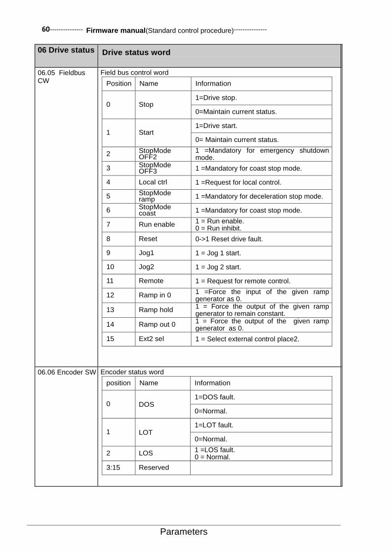
60--------------- Firmware manual(Standard control procedure)---------------
Parameters
06 Drive status Drive status word
06.05 Fieldbus CW
Field bus control word
Position Name Information
0 Stop 1=Drive stop.
0=Maintain current status.
1 Start 1=Drive start.
0= Maintain current status.
2 StopMode OFF2
1 =Mandatory for emergency shutdown mode.
3 StopMode OFF3 1 =Mandatory for coast stop mode.
4 Local ctrl 1 =Request for local control.
5 StopMode ramp 1 =Mandatory for deceleration stop mode.
6 StopMode coast 1 =Mandatory for coast stop mode.
7 Run enable 1 = Run enable. 0 = Run inhibit.
8 Reset 0->1 Reset drive fault.
9 Jog1 1 = Jog 1 start.
10 Jog2 1 = Jog 2 start.
11 Remote 1 = Request for remote control.
12 Ramp in 0 1 =Force the input of the given ramp generator as 0.
13 Ramp hold 1 = Force the output of the given ramp generator to remain constant.
14 Ramp out 0 1 = Force the output of the given ramp generator as 0.
15 Ext2 sel 1 = Select external control place2.
06.06 Encoder SW Encoder status word
position Name Information
0 DOS 1=DOS fault.
0=Normal.
1 LOT 1=LOT fault.
0=Normal.
2 LOS 1 =LOS fault. 0 = Normal.
3:15 Reserved

--------------- Firmware manual(Standard control procedure)--------------- 61
Parameters
06 Drive status Drive status word
06.07 PosCtrl SW Position control status word
Position
Designation Information
0 Pos sync 1=Position synchronized.
0=Position not synchronized.
1 Pos end 1= Position completed.
0=Position not completed.
2 Mark rdy 1 =Reference signal ready. 0 = Reference signal not detected.
3 Mark load 1 = Loaded. 0 = Not loaded.
4:15 Reserved

62--------------- Firmware manual(Standard control procedure)---------------
Parameters
08 Fault&Alarm Log
08 Fault & Alarm Log Fault and Alarm log
08.00 Alarm Code Latest Alarm Code. -
08.01 Fault Code Latest Fault Code. -
09 System Info
09 System Info Drive system Info
09.00 Driver ID Drive hardware code. -
09.01 Drive type Drive type. -
09.02 Firmware version Drive firmware version. -
09.03 Encoder type The encoder type indentified by the expansion card
slot SLOT1. -
09.04 PWM freq The actual applicated carrier frequency of the
system. -
09.05 App macro active The actual applicated macro of the system. -
09.06 PM phase CM
The angle accuracy is sufficient to use when the
common mode signal strength identified by the
synchronous motor rotor initial angle reach to
150. It is used to instruct the user to adjust the
parameter 60.11 of the injection current size to
achieve the best search.
-
09.07 PM phase DIF
The angle accuracy is sufficient to use when the
differential-mode mode signal strength identified
by the synchronous motor rotor initial angle reach
to 150. It will cause too loud noise if inject too
much current; while the insufficient current signal
strength may cause search error.
-

--------------- Firmware manual(Standard control procedure)--------------- 63
Parameters
10 Start/Stop/Dir
10 Start/Stop/Dir Selection of signal sources of start / stop / direction
Def
10.00 Ext1 start func Select the signal source of the external control 1 (EXT1) start and the stop command. Note: this parameter cannot be changed when the drive is running.
In1FWD,
In2
RVD=[2]
Not selected The start function of control1 is not selected. 0
In1 RUN, In2 DIR
The signal source selected by the parameter of 10.01Ext1startin1 (Control 1 of the input 1) is the start signal (0= Stop,1= Start) .. selected by the parameter of 10.02Ext1 startin2 (Control 1 of the input 2) is the direction signal (0=Positive, 1=Reverse).
1
In1 FWD, In2 REV
The signal sources of the start and stop command are selected by the parameters of 10.01Ext1startin1 (Control 1 of the input 1) and 10.02Ext1startin2 (Control 1 of the input 2). The state transition of the signal source bit is explained as follows:
The status of the input1 of control1
The status of the input2 of control1
Command
0 0 Stop
1 0 Forward start
0 1 Reverse start
1 1 Stop
2
RUN/STOP/DIR
The signal sources of the start and stop command are selected by the parameters of 10.01 Ext1 start in1 (Control 1 of the input 1), 10.02 Ext1 start in2 (Control 1 of the input 2) and 10.03 Ext1 start in3 (Control 1 of the input 3). The state transition of the signal source bit is explained as follows:
The status of the input1 of control1
The status of the input2 of control1
The status of the input3 of control1
Command
0 1 0 0 Forward start
0 1 0 1 Reverse start
X 1 X Stop
0 0 X Change Dir
3
FWD/REV/STOP
The signal sources of the start and stop command are selected by the parameters of 10.01 Ext1 start in1 (Control 1 of the input 1), 10.02 Ext1 start in2 (Control 1 of the input 2) and 10.03 Ext1 start in3 (Control 1 of the input 3). The state transition of the signal source bit is explained as follows:
The status of the input1 of control1
The status of the input2 of control1
The status of the input3 of control1
Command
0 1 0 0 Forward start
0 0 1 0 Reverse start
X X 1 Stop
1 1 0 Stop
4
Fieldbus Fieldbus communication control word decision. 5
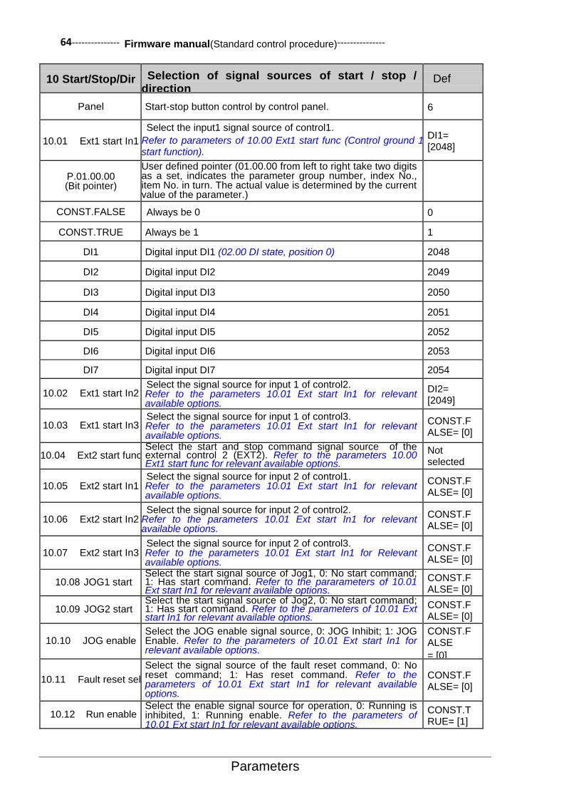
64--------------- Firmware manual(Standard control procedure)---------------
Parameters
10 Start/Stop/Dir Selection of signal sources of start / stop / direction
Def
Panel Start-stop button control by control panel. 6
10.01 Ext1 start In1
Select the input1 signal source of control1.
Refer to parameters of 10.00 Ext1 start func (Control ground 1 start function).
DI1= [2048]
P.01.00.00 (Bit pointer)
User defined pointer (01.00.00 from left to right take two digits as a set, indicates the parameter group number, index No., item No. in turn. The actual value is determined by the current value of the parameter.)
CONST.FALSE Always be 0 0
CONST.TRUE Always be 1 1
DI1 Digital input DI1 (02.00 DI state, position 0) 2048
DI2 Digital input DI2 2049
DI3 Digital input DI3 2050
DI4 Digital input DI4 2051
DI5 Digital input DI5 2052
DI6 Digital input DI6 2053
DI7 Digital input DI7 2054
10.02 Ext1 start In2 Select the signal source for input 1 of control2. Refer to the parameters 10.01 Ext start In1 for relevant available options.
DI2= [2049]
10.03 Ext1 start In3 Select the signal source for input 1 of control3. Refer to the parameters 10.01 Ext start In1 for relevant available options.
CONST.FALSE= [0]
10.04 Ext2 start func Select the start and stop command signal source of the external control 2 (EXT2). Refer to the parameters 10.00 Ext1 start func for relevant available options.
Not selected [0]
10.05 Ext2 start In1 Select the signal source for input 2 of control1. Refer to the parameters 10.01 Ext start In1 for relevant available options.
CONST.FALSE= [0]
10.06 Ext2 start In2 Select the signal source for input 2 of control2.
Refer to the parameters 10.01 Ext start In1 for relevant available options.
CONST.FALSE= [0]
10.07 Ext2 start In3 Select the signal source for input 2 of control3. Refer to the parameters 10.01 Ext start In1 for Relevant available options.
CONST.FALSE= [0]
10.08 JOG1 start Select the start signal source of Jog1, 0: No start command; 1: Has start command. Refer to the pararameters of 10.01 Ext start In1 for relevant available options.
CONST.FALSE= [0]
10.09 JOG2 start Select the start signal source of Jog2, 0: No start command; 1: Has start command. Refer to the parameters of 10.01 Ext start In1 for relevant available options.
CONST.FALSE= [0]
10.10 JOG enable Select the JOG enable signal source, 0: JOG Inhibit; 1: JOG Enable. Refer to the parameters of 10.01 Ext start In1 for relevant available options.
CONST.FALSE
= [0]
10.11 Fault reset sel
Select the signal source of the fault reset command, 0: No reset command; 1: Has reset command. Refer to the parameters of 10.01 Ext start In1 for relevant available options.
CONST.FALSE= [0]
10.12 Run enable Select the enable signal source for operation, 0: Running is inhibited, 1: Running enable. Refer to the parameters of 10.01 Ext start In1 for relevant available options.
CONST.TRUE= [1]

--------------- Firmware manual(Standard control procedure)--------------- 65
Parameters
10 Start/Stop/Dir Selection of signal sources of start / stop / direction
Def
10.13 Emergency stop
Select the signal source of the emergency stop command, 0: Emergency stop; 1: Keep the current state. Refer to the parameters of 10.01 Ext start In1 for relevant available options.
CONST.TRUE= [1]
10.14 EM stop mode Selection of emergency stop mode. OFF21=[0]
OFF1 Deceleration stop, Deceleration time is the acceleration and deceleration time1.
0
OFF2 Coast stop 1
OFF3 Deceleration stop, Deceleration time is the emergency stop
time. 2
10.15 Start enable Select the start enable signal source, 0: Start inhibit; 1: Start enable. Refer to the parameters of 10.01 Ext start In1 for relevant available options.
CONST.TRUE= [1]
10.16 Upper limit
Select the signal source of the upper limit, 0: Limit activated; 1: Limit not activated.
Refer to the parameters of 10.01 Ext start In1 for relevant available options.
CONST.TRUE= [1]
10.17 Lower limit
Select the signal source of the lower limit. 0: Limit activated; 2: Limit not activated.
Refer to the parameters of 10.01 Ext start In1 for relevant available options.
CONST.TRUE= [1]
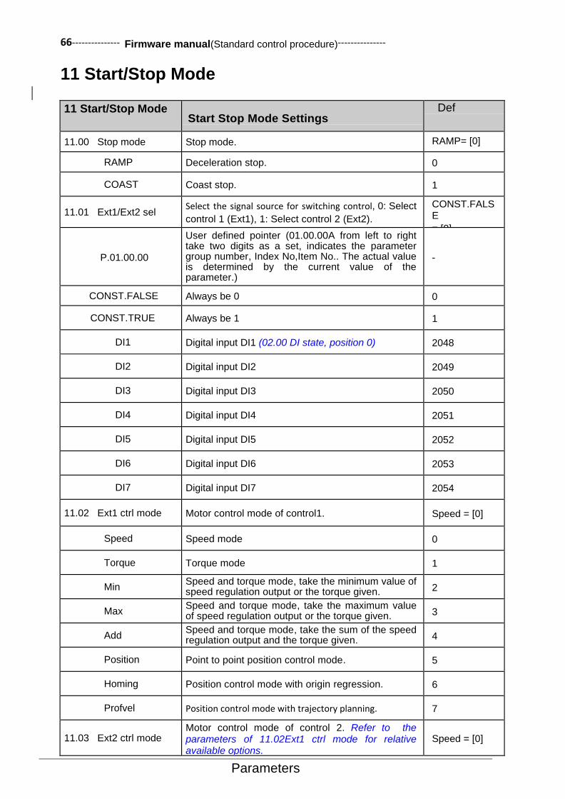
66--------------- Firmware manual(Standard control procedure)---------------
Parameters
11 Start/Stop Mode
11 Start/Stop Mode
Start Stop Mode Settings
Def
11.00 Stop mode Stop mode. RAMP= [0]
RAMP Deceleration stop. 0
COAST Coast stop. 1
11.01 Ext1/Ext2 sel Select the signal source for switching control, 0: Select
control 1 (Ext1), 1: Select control 2 (Ext2).
CONST.FALSE
= [0]
P.01.00.00
User defined pointer (01.00.00A from left to right take two digits as a set, indicates the parameter group number, Index No,Item No.. The actual value is determined by the current value of the parameter.)
-
CONST.FALSE Always be 0 0
CONST.TRUE Always be 1 1
DI1 Digital input DI1 (02.00 DI state, position 0) 2048
DI2 Digital input DI2 2049
DI3 Digital input DI3 2050
DI4 Digital input DI4 2051
DI5 Digital input DI5 2052
DI6 Digital input DI6 2053
DI7 Digital input DI7 2054
11.02 Ext1 ctrl mode Motor control mode of control1. Speed = [0]
Speed Speed mode 0
Torque Torque mode 1
Min Speed and torque mode, take the minimum value of speed regulation output or the torque given. 2
Max Speed and torque mode, take the maximum value of speed regulation output or the torque given. 3
Add Speed and torque mode, take the sum of the speed regulation output and the torque given. 4
Position Point to point position control mode. 5
Homing Position control mode with origin regression. 6
Profvel Position control mode with trajectory planning. 7
11.03 Ext2 ctrl mode Motor control mode of control 2. Refer to the parameters of 11.02Ext1 ctrl mode for relative available options.
Speed = [0]
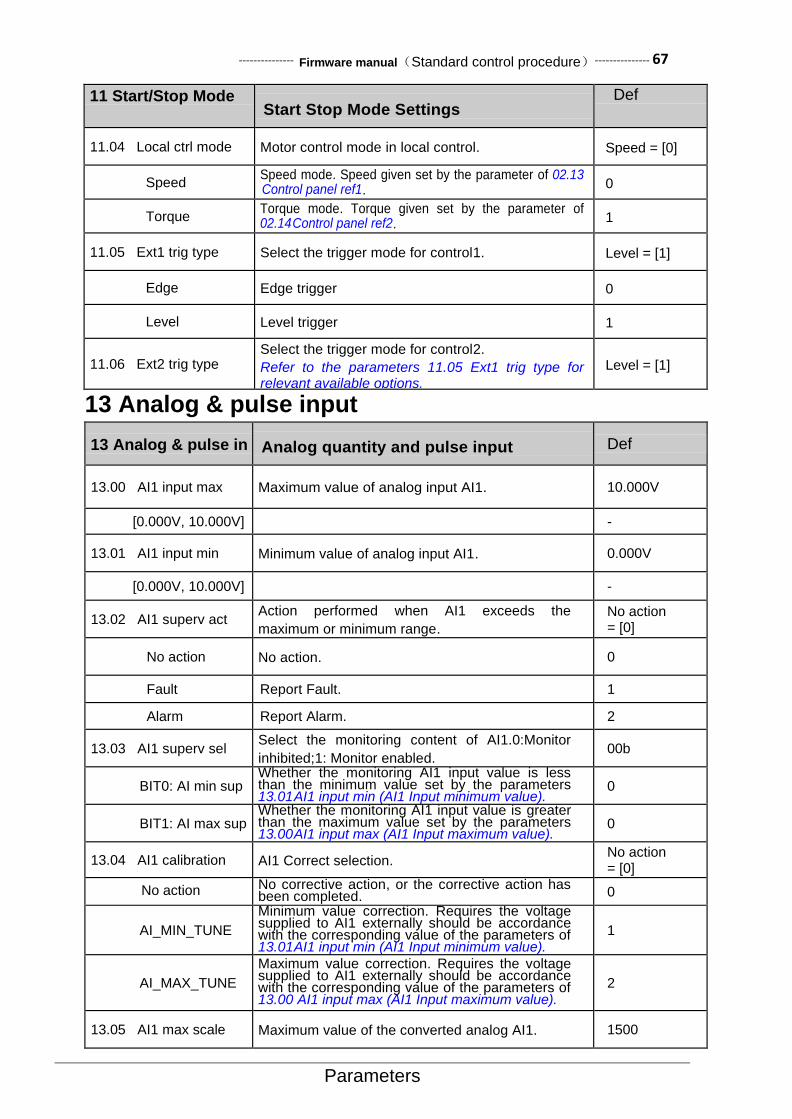
--------------- Firmware manual(Standard control procedure)--------------- 67
Parameters
11 Start/Stop Mode
Start Stop Mode Settings
Def
11.04 Local ctrl mode Motor control mode in local control. Speed = [0]
Speed Speed mode. Speed given set by the parameter of 02.13 Control panel ref1. 0
Torque Torque mode. Torque given set by the parameter of 02.14 Control panel ref2. 1
11.05 Ext1 trig type Select the trigger mode for control1. Level = [1]
Edge Edge trigger 0
Level Level trigger 1
11.06 Ext2 trig type Select the trigger mode for control2.
Refer to the parameters 11.05 Ext1 trig type for relevant available options.
Level = [1]
13 Analog & pulse input
13 Analog & pulse in Analog quantity and pulse input Def
13.00 AI1 input max Maximum value of analog input AI1. 10.000V
[0.000V, 10.000V] -
13.01 AI1 input min Minimum value of analog input AI1. 0.000V
[0.000V, 10.000V] -
13.02 AI1 superv act Action performed when AI1 exceeds the
maximum or minimum range.
No action = [0]
No action No action. 0
Fault Report Fault. 1
Alarm Report Alarm. 2
13.03 AI1 superv sel Select the monitoring content of AI1.0:Monitor
inhibited;1: Monitor enabled. 00b
BIT0: AI min sup Whether the monitoring AI1 input value is less than the minimum value set by the parameters 13.01 AI1 input min (AI1 Input minimum value).
0
BIT1: AI max sup Whether the monitoring AI1 input value is greater than the maximum value set by the parameters 13.00 AI1 input max (AI1 Input maximum value).
0
13.04 AI1 calibration AI1 Correct selection. No action = [0]
No action No corrective action, or the corrective action has been completed. 0
AI_MIN_TUNE
Minimum value correction. Requires the voltage supplied to AI1 externally should be accordance with the corresponding value of the parameters of 13.01 AI1 input min (AI1 Input minimum value).
1
AI_MAX_TUNE
Maximum value correction. Requires the voltage supplied to AI1 externally should be accordance with the corresponding value of the parameters of 13.00 AI1 input max (AI1 Input maximum value).
2
13.05 AI1 max scale Maximum value of the converted analog AI1. 1500

68--------------- Firmware manual(Standard control procedure)---------------
Parameters
13 Analog & pulse in Analog quantity and pulse input Def
[-32768, 32767] The output value of the converted AI1 maximum input voltage. -
13.06 AI1 min scale The minimum value of the converted analog AI1. 0
[-32768, 32767] The output value of the converted AI1 minimum input voltage.
-
13.07 AI1 sim enable In debugging or other applications, user can enable the AI1 simulation function of the analog input by this parameter.
Disable = [0]
Disable Turn off the simulation mode. The converted output of AI1 depends on the input voltage of AI1. 0
Enable Enable simulation mode. The converted output of AI1 depends on the parameters of 13.08AI1 sim data (AI1simulation data).
1
13.08 AI1 sim data Simulation data of anolog AI1. 0
[-32768, 32767] Set the converted output of AI1 when the emulation mode of AI1 is enabled. -
13.09 AI1 filter time Define the first-order low-pass filtering time
constant of analog AI1. 0.10s
[0.01s, 10.00s] Filter time constant. -
13.10 AI2 input max Maximum value of analog input AI2。 10.000V Or 20.000mA [0.000mA, 20.000mA]
or [0.000V, 10.000V]
Range and unit by parameter13.17 AI2 input
type(AI2Input type)Decision.
13.11 AI2 input min Minimum value of analog input AI2. 0.000 V Or 0.000mA
[0.000mA, 20.000mA] or [0.000V, 10.000V]
The value range and unit are determined by the
parameter of 13.17 AI2 input type (AI2 Input type).
Decision.
13.12 AI2 superv act
The performed action when AI2 exceeds the maximum or minimum range. Refer to the parameters of 13.02 AI1 superv act (AI1 Monitoring action) for relative available options.
No action = [0]
13.13 AI2 superv sel Select the contents of AI2 monitoring. Refer to the parameters of 13.03 AI1 superv sel (AI1 Monitoring options) for relative available options.
00b
13.14 AI2 calibration AI2 calibration selection. Refer to the parameters of 13.04 AI1 calibration (AI1 Calibration selection) for relative available options.
No action = [0]
13.15 AI2 max scale Maximum value of the converted analog AI2. 1500
[-32768, 32767] The output value of the converted AI2 maximum input voltage. -
13.16 AI2 min scale Minimum value of the converted analog AI2. 0
[-32768, 32767] The output value of the converted AI2 minimum input voltage. -
13.17 AI2 input type
The input type of analog AI2. Must be consistent with the dial-up position of the terminal panel dial-up switch S1. Note: when using the 4~20mA current mode senso, user need to manually set the parameters of 13.11 AI2 input min (AI2 Input minimum value) as 4.000mA.
Voltage = [0]

--------------- Firmware manual(Standard control procedure)--------------- 69
Parameters
13 Analog & pulse in Analog quantity and pulse input Def
Voltage Dial code switch or jumper wire to the letter “V”
side, select the voltage type input. 0
Current Dial switch to the letter “I” side, select the current
type input. 1
13.18 AI2 sim enable Simulation enable of analog AI2. Refer to the parameters of 13.07 AI1 sim enable (AI1 Simulation enable).
Disable = [0]
13.19 AI2 sim data
Simulation data of analog AI2.
Refer to the parameters of 13.08 AI1 sim data (AI1
Simulation data).
0
13.20 AI2 filter time Define the first-order low-pass filter time constant
of analog AI2. 0.10s
[0.01s, 10.00s] Filter time constant. -
13.21 AI3 input max Maximum value of analog input AI3. 10.000V or 20.000mA
[0.000mA, 20.000mA] or [0.000V, 10.000V]
The value range and the units are determined by
the parameter of 13.28 AI3 input type (AI3 Input
type).
-
13.22 AI3 input min Minimum value of analog input AI3. 0.000V or 0.000mA
[0.000mA, 20.000mA] or [0.000V, 10.000V]
The value range and the units are determined by
the parameter of 13.28 AI3 input type (AI3 Input
type). Decision。
-
13.23 AI3 superv act
Action performed when AI3 exceeds the maximum or the minimum range. Refer to the parameters of 13.02 AI1 superv act (AI1 Monitoring action) for relevant available options.
No action = [0]
13.24 AI3 superv sel Select the contents of the AI3 monitor. Refer to the parameters of 13.03 AI1 superv sel (AI1Monitoring options) for relevant available options.
00b
13.25 AI3 calibration AI3 calibration selection. Refer to the parameters of 13.04 AI1 calibration (AI1 Calibration selection) for relevant available options.
None = [0]
13.26 AI3 max scale Maximum value of the converted analog AI3. 1500
[-32768, 32767] The output value of the converted AI3 maximum input voltage.
-
13.27 AI3 min scale Minimum value of the converted analog AI3. 0
[-32768, 32767] The output value of the converted AI3 minimum input voltage.
-
13.28 AI3 input type
The anlog AI3 input type. It must be consistent with the dial position of the terminal panel dial switch S2. Note: when using the 4~20mA current type sensor, user need to manually set the parameters of 13.22 AI3 input min(AI3 Input minimum value)as 4.000mA. Refer to the parameters of 13.17 AI2 input type (AI2 Input type).
Voltage = [0]
13.29 AI3 sim enable Simulation enable of analog AI3. Refer to the parameters 13.07 AI1 sim enable (AI1 Simulation enable).
Disable = [0]
13.30 AI3 sim data Simulation data of analog AI3. Refer to the parameters of 13.08 AI1 sim data (AI1 simulation data).
0
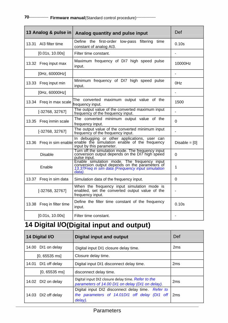
70--------------- Firmware manual(Standard control procedure)---------------
Parameters
13 Analog & pulse in Analog quantity and pulse input Def
13.31 AI3 filter time Define the first-order low-pass filtering time
constant of analog AI3. 0.10s
[0.01s, 10.00s] Filter time constant. -
13.32 Freq input max Maximum frequency of DI7 high speed pulse
input. 10000Hz
[0Hz, 60000Hz] -
13.33 Freq input min Minimum frequency of DI7 high speed pulse
input. 0Hz
[0Hz, 60000Hz] -
13.34 Freq in max scale The converted maximum output value of the frequency input.
1500
[-32768, 32767] The output value of the converted maximum input frequency of the frequency input. -
13.35 Freq inmin scale The converted minimum output value of the
frequency input. 0
[-32768, 32767] The output value of the converted minimum input frequency of the frequency input. -
13.36 Freq in sim enable In debugging or other applications, user can enable the simulation enable of the frequency input by this parameter.
Disable = [0]
Disable Turn off the simulation mode. The frequency input conversion output depends on the DI7 high speed pulse input.
0
Enable
Enable simulation mode. The frequency input conversion output depends on the parameters of 13.37Freq in sim data (Frequency input simulation data).
1
13.37 Freq in sim data Simulation data of the frequency input. 0
[-32768, 32767] When the frequency input simulation mode is enabled, set the converted output value of the frequency input.
-
13.38 Freq in filter time Define the filter time constant of the frequency
input. 0.10s
[0.01s, 10.00s] Filter time constant. -
14 Digital I/O(Digital input and output)
14 Digital I/O Digital input and output Def
14.00 DI1 on delay Digital input DI1 closure delay time. 2ms
[0, 65535 ms] Closure delay time.
14.01 DI1 off delay Digital input DI1 disconnect delay time. 2ms
[0, 65535 ms] disconnect delay time.
14.02 DI2 on delay Digital input DI2 closure delay time. Refer to the
parameters of 14.00 DI1 on delay (DI1 on delay). 2ms
14.03 DI2 off delay
Digital input DI2 disconnect delay time. Refer to
the parameters of 14.01DI1 off delay (DI1 off
delay).
2ms
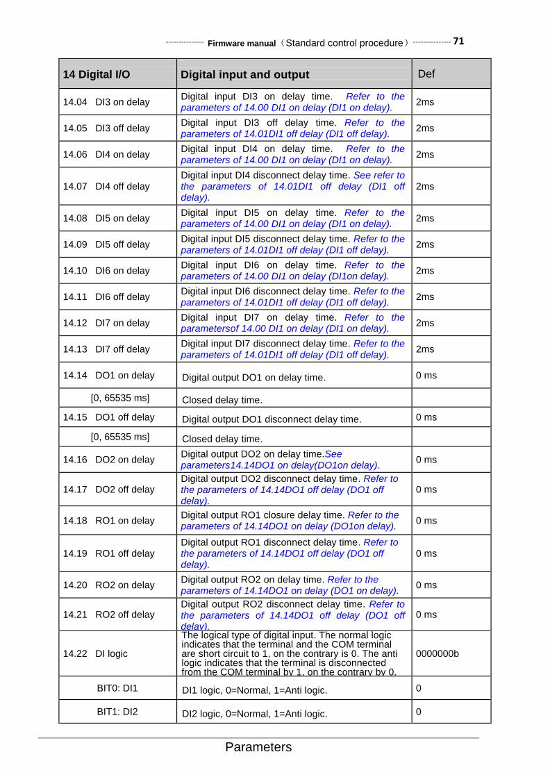
--------------- Firmware manual(Standard control procedure)--------------- 71
Parameters
14 Digital I/O Digital input and output Def
14.04 DI3 on delay Digital input DI3 on delay time. Refer to the parameters of 14.00 DI1 on delay (DI1 on delay).
2ms
14.05 DI3 off delay Digital input DI3 off delay time. Refer to the parameters of 14.01DI1 off delay (DI1 off delay).
2ms
14.06 DI4 on delay Digital input DI4 on delay time. Refer to the parameters of 14.00 DI1 on delay (DI1 on delay).
2ms
14.07 DI4 off delay Digital input DI4 disconnect delay time. See refer to the parameters of 14.01DI1 off delay (DI1 off delay).
2ms
14.08 DI5 on delay Digital input DI5 on delay time. Refer to the parameters of 14.00 DI1 on delay (DI1 on delay).
2ms
14.09 DI5 off delay Digital input DI5 disconnect delay time. Refer to the parameters of 14.01DI1 off delay (DI1 off delay).
2ms
14.10 DI6 on delay Digital input DI6 on delay time. Refer to the parameters of 14.00 DI1 on delay (DI1on delay).
2ms
14.11 DI6 off delay Digital input DI6 disconnect delay time. Refer to the parameters of 14.01DI1 off delay (DI1 off delay).
2ms
14.12 DI7 on delay Digital input DI7 on delay time. Refer to the parametersof 14.00 DI1 on delay (DI1 on delay).
2ms
14.13 DI7 off delay Digital input DI7 disconnect delay time. Refer to the parameters of 14.01DI1 off delay (DI1 off delay).
2ms
14.14 DO1 on delay Digital output DO1 on delay time. 0 ms
[0, 65535 ms] Closed delay time.
14.15 DO1 off delay Digital output DO1 disconnect delay time. 0 ms
[0, 65535 ms] Closed delay time.
14.16 DO2 on delay Digital output DO2 on delay time.See parameters14.14DO1 on delay(DO1on delay).
0 ms
14.17 DO2 off delay Digital output DO2 disconnect delay time. Refer to the parameters of 14.14DO1 off delay (DO1 off delay).
0 ms
14.18 RO1 on delay Digital output RO1 closure delay time. Refer to the parameters of 14.14DO1 on delay (DO1on delay).
0 ms
14.19 RO1 off delay Digital output RO1 disconnect delay time. Refer to the parameters of 14.14DO1 off delay (DO1 off delay).
0 ms
14.20 RO2 on delay Digital output RO2 on delay time. Refer to the parameters of 14.14DO1 on delay (DO1 on delay).
0 ms
14.21 RO2 off delay Digital output RO2 disconnect delay time. Refer to the parameters of 14.14DO1 off delay (DO1 off delay).
0 ms
14.22 DI logic
The logical type of digital input. The normal logic indicates that the terminal and the COM terminal are short circuit to 1, on the contrary is 0. The anti logic indicates that the terminal is disconnected from the COM terminal by 1, on the contrary by 0.
0000000b
BIT0: DI1 DI1 logic, 0=Normal, 1=Anti logic. 0
BIT1: DI2 DI2 logic, 0=Normal, 1=Anti logic. 0
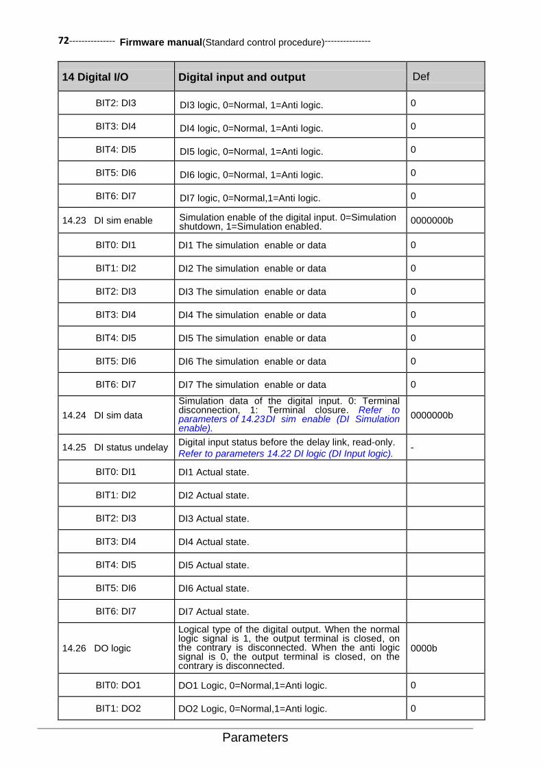
72--------------- Firmware manual(Standard control procedure)---------------
Parameters
14 Digital I/O Digital input and output Def
BIT2: DI3 DI3 logic, 0=Normal, 1=Anti logic. 0
BIT3: DI4 DI4 logic, 0=Normal, 1=Anti logic. 0
BIT4: DI5 DI5 logic, 0=Normal, 1=Anti logic. 0
BIT5: DI6 DI6 logic, 0=Normal, 1=Anti logic. 0
BIT6: DI7 DI7 logic, 0=Normal,1=Anti logic. 0
14.23 DI sim enable Simulation enable of the digital input. 0=Simulation shutdown, 1=Simulation enabled.
0000000b
BIT0: DI1 DI1 The simulation enable or data 0
BIT1: DI2 DI2 The simulation enable or data 0
BIT2: DI3 DI3 The simulation enable or data 0
BIT3: DI4 DI4 The simulation enable or data 0
BIT4: DI5 DI5 The simulation enable or data 0
BIT5: DI6 DI6 The simulation enable or data 0
BIT6: DI7 DI7 The simulation enable or data 0
14.24 DI sim data
Simulation data of the digital input. 0: Terminal disconnection, 1: Terminal closure. Refer to parameters of 14.23 DI sim enable (DI Simulation enable).
0000000b
14.25 DI status undelay Digital input status before the delay link, read-only.
Refer to parameters 14.22 DI logic (DI Input logic). -
BIT0: DI1 DI1 Actual state.
BIT1: DI2 DI2 Actual state.
BIT2: DI3 DI3 Actual state.
BIT3: DI4 DI4 Actual state.
BIT4: DI5 DI5 Actual state.
BIT5: DI6 DI6 Actual state.
BIT6: DI7 DI7 Actual state.
14.26 DO logic
Logical type of the digital output. When the normal logic signal is 1, the output terminal is closed, on the contrary is disconnected. When the anti logic signal is 0, the output terminal is closed, on the contrary is disconnected.
0000b
BIT0: DO1 DO1 Logic, 0=Normal,1=Anti logic. 0
BIT1: DO2 DO2 Logic, 0=Normal,1=Anti logic. 0

--------------- Firmware manual(Standard control procedure)--------------- 73
Parameters
14 Digital I/O Digital input and output Def
BIT2: RO1 RO1 Logic, 0=Normal, 1=Anti logic. 0
BIT3: RO2 RO2 Logic, 0=Normal, 1=Anti logic. 0
14.27 DO sim enable Digital output simulation enable, 0: Simulation
shutdown, 1: Simulation enable. 0000b
BIT0: DO1 DO1 simulation enable or data 0
BIT1: DO2 DO2 simulation enable or data 0
BIT2: RO1 RO1 simulation enable or data 0
BIT3: RO2 RO2 simulation enable or data 0
14.28 DO sim data
Simulation data of the digital output. 0: Terminal disconnection, 1: Terminal closure. Refer to parameters 14.27 DO sim enable (DO Simulation enable).
0000b
14.29 DO1 source Set the signal source DO1. Refer to parameters
14.26 DO logic (DO Output logic) for the meaning of
0 and 1.
Running = [6148]
P.01.00.00
User defined pointer (01.00.00 from left to right take two digits as a set, indicates the parameter group number, index and item. The actual value is determined by the current value of the parameter).
-
CONST.FALSE Has been 0 0
CONST.TRUE Has been 1 1
Ready Ready (06.00 Status word 1, position 0) 6144
Running Drive running (06.00 Status word 1, position 4) 6148
Fault Driver fault (06.00 Status word 1, position 1) 6145
Alarm Drive alarm (06.00 Status word 1, position 2) 6146
Start req Drive received start request (06.00 Status word 1, position 6)
6150
Ext2 Drive controlled by external control2 (06.00 Status word 1, position 14)
6158
Loc ctrl Drive in local control (06.00 Status word 1, position
15) 6159
Zero speed Drive output is 0 (06.03 Speed control status word, position 0)
6192
Reverse Drive output is negative (06.03 Speed control status word, position 1)
6193
At setpoint Drive output is equal with settings (06.03 Speed control status word, position 4)
6196
Torq limit Drive torque limit running (06.03 Speed control status word, position 13)
6205
Speed limit Drive speed limit running (06.03 Speed control status word, position 14)
6206
14.30 DO2 source
Set the signal source of DO2. Refer to parameters
14.29 DO1 source (DO1 Signal source) for relevant
available options.
Fault = [6145]
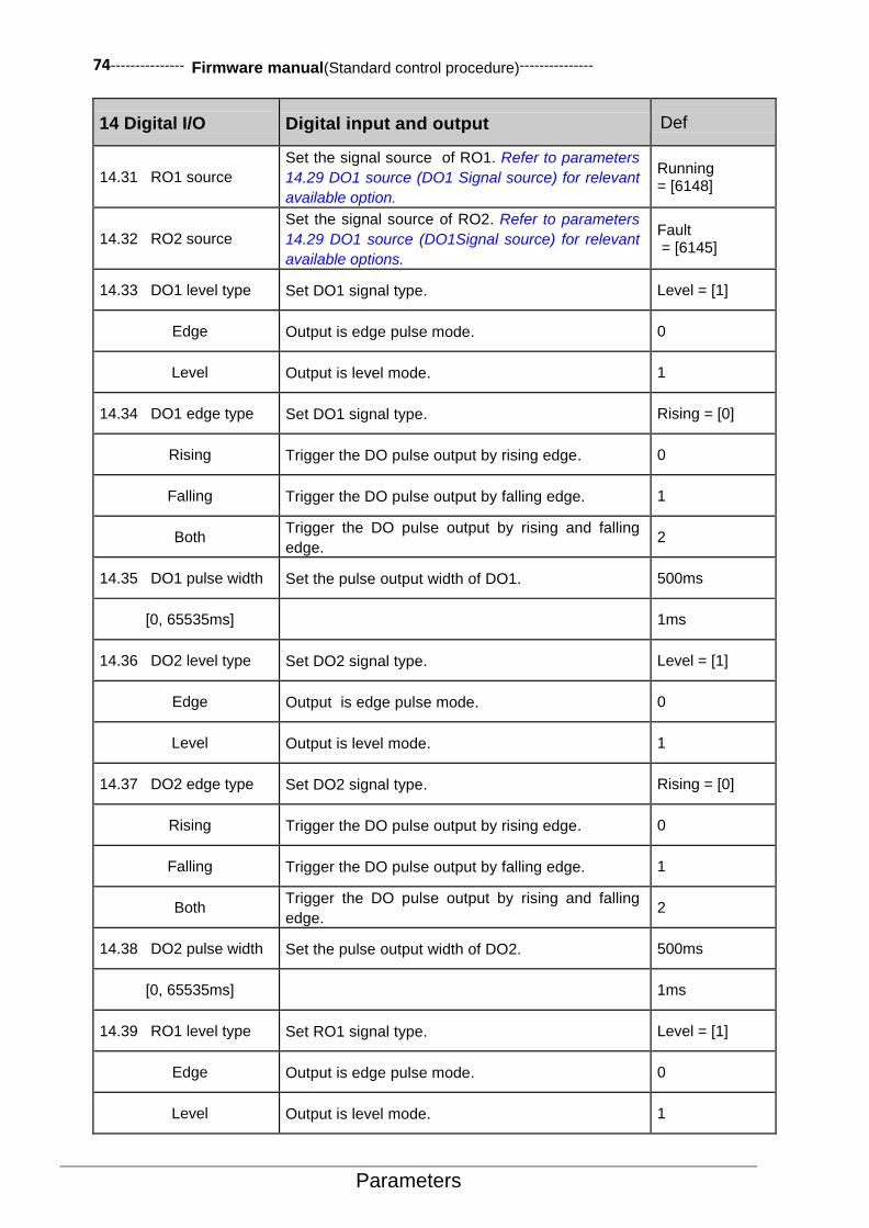
74--------------- Firmware manual(Standard control procedure)---------------
Parameters
14 Digital I/O Digital input and output Def
14.31 RO1 source
Set the signal source of RO1. Refer to parameters
14.29 DO1 source (DO1 Signal source) for relevant
available option.
Running = [6148]
14.32 RO2 source
Set the signal source of RO2. Refer to parameters
14.29 DO1 source (DO1Signal source) for relevant
available options.
Fault = [6145]
14.33 DO1 level type Set DO1 signal type. Level = [1]
Edge Output is edge pulse mode. 0
Level Output is level mode. 1
14.34 DO1 edge type Set DO1 signal type. Rising = [0]
Rising Trigger the DO pulse output by rising edge. 0
Falling Trigger the DO pulse output by falling edge. 1
Both Trigger the DO pulse output by rising and falling
edge. 2
14.35 DO1 pulse width Set the pulse output width of DO1. 500ms
[0, 65535ms] 1ms
14.36 DO2 level type Set DO2 signal type. Level = [1]
Edge Output is edge pulse mode. 0
Level Output is level mode. 1
14.37 DO2 edge type Set DO2 signal type. Rising = [0]
Rising Trigger the DO pulse output by rising edge. 0
Falling Trigger the DO pulse output by falling edge. 1
Both Trigger the DO pulse output by rising and falling
edge. 2
14.38 DO2 pulse width Set the pulse output width of DO2. 500ms
[0, 65535ms] 1ms
14.39 RO1 level type Set RO1 signal type. Level = [1]
Edge Output is edge pulse mode. 0
Level Output is level mode. 1

--------------- Firmware manual(Standard control procedure)--------------- 75
Parameters
14 Digital I/O Digital input and output Def
14.40 RO1edge type Set RO1 signal type. Rising = [0]
Rising Trigger the DO pulse output by rising edge. 0
Falling Trigger the DO pulse output by falling edge. 1
Both Trigger the DO pulse output by rising and falling
edge. 2
14.41 RO1 pulse width Set the pulse output width of RO1. 500ms
[0, 65535ms] 1ms
14.42 RO2 level type
Set RO2 signal type. Level = [1]
Edge Output is edge pulse mode. 0
Level Output is level mode. 1
14.43 RO2 edge type Set RO2 signal type. Rising = [0]
Rising Trigger the DO pulse output by rising edge. 0
Falling Trigger the DO pulse output by falling edge. 1
Both Trigger the DO pulse output by rising and falling
edge. 2
14.44 RO2 pulse width Set the pulse output width of RO2. 500ms
[0, 65535ms] 1ms
14.45 DO JOG mask Set whether the DO output is shielded or not at
JOG. Refer to 14.26 DO logic. 0
15 Analog & pulse out
15 Analog & pulse out Analog output and pulse output Def
15.00 AO1 source Select the signal source of analog output AO1. Motor speed =[256]
P.01.00
User defined pointer (01.00 from left to right take two digits as a set, indicates the parameter group number and index. The actual value is determined by the current value of the parameter).
-
Zero Always be 0. 0
Motor speed Refer to parameters 01.00 Motor speed (motor
speed). 256
Output frequency Refer to parameters 01.01 Output frequency (output
frequency). 257
DC bus voltage Refer to parameters 01.02 DC bus voltage (DC Bus
Voltage). 258

76--------------- Firmware manual(Standard control procedure)---------------
Parameters
15 Analog & pulse out Analog output and pulse output Def
Motor current Refer to parameters 01.03 Motor current (Motor
current). 259
Motor current % Refer to parameters 01.04 Motor current % (Motor
current percentage). 260
Motor slip est Refer to parameters 01.12 Motor slip est
(Estimated value of motor slip). 268
Output voltage Refer to parameters 01.21 Output voltage (output
voltage). 277
Motor torque Refer to parameters01.22 Motor torque (Motor
torque). 278
Motor temperature Refer to parameters 01.23 Motor temperature
(Motor temperature). 279
Output power Refer to parameters 01.28 Output power (output
power). 284
15.01 AO1 output max Define the maximum value of the analog output
AO1 output. 10.000V
[0.000mA, 20.000mA] Or [0.000V, 10.000V]
The value range and the unit are determined by the
parameter 15.08 AO1 output type (AO1 type of
output).
-
15.02 AO1 output min Define the minimum value of the analog output
AO1 output. 0.000V
[0.000mA, 20.000mA] Or [0.000V, 10.000V]
The value range and the unit are determined by the
parameter 15.08 AO1 output type (AO1 type of
output).
-
15.03 AO1 source max
Define the maximum value of the signal selected via the parameter 15.00 AO1 source (AO1signal source). Refer to parameters of 15.07 AO1 output mode (AO1 Output mode) for corresponding output value of AO1.
15000
[-32768, 32767] -
15.04 AO1 source min
Define the minimum value of the signal selected via the parameter 15.00 AO1 source (AO1signal source). Refer to parameters of 15.07 AO1 output mode (AO1Output mode) for corresponding output value of AO1.
0
[-32768, 32767] -
15.05 AO1 sim data
Set the output voltage or current of AO1 when simulation enabled. 10.000V
[0mA, 20.000mA] Or [0V, 10.000V]
-
15.06 AO1 sim enable In debugging or other application occasions, user can enable the simulation function of the analog output of AO1 via this parameter.
Disable = [0]
Disable Simulation function turn off, the output voltage or current of AO1 depends on the actual value of the signal source.
0
Enable
Simulation function enabled. The output voltage or current of AO1 depends on the setting value of the parameters 15.05 AO1 sim data (AO1 simulation data).
1
15.07 AO1 output mode The output mode determines the correspondence between the maximum and minimum values of the AO1 signal source and the AO1 output.
Normal = [0]
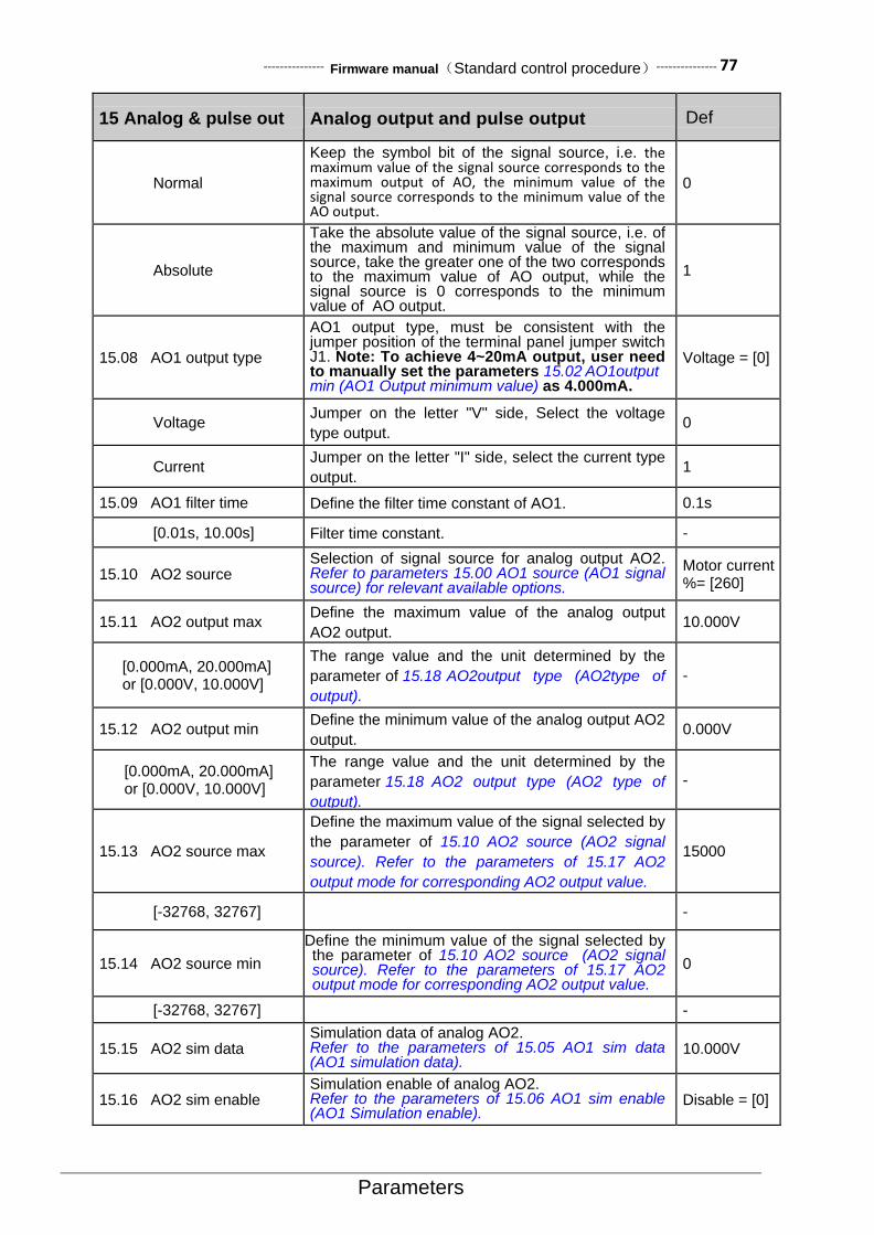
--------------- Firmware manual(Standard control procedure)--------------- 77
Parameters
15 Analog & pulse out Analog output and pulse output Def
Normal
Keep the symbol bit of the signal source, i.e. the maximum value of the signal source corresponds to the maximum output of AO, the minimum value of the signal source corresponds to the minimum value of the AO output.
0
Absolute
Take the absolute value of the signal source, i.e. of the maximum and minimum value of the signal source, take the greater one of the two corresponds to the maximum value of AO output, while the signal source is 0 corresponds to the minimum value of AO output.
1
15.08 AO1 output type
AO1 output type, must be consistent with the jumper position of the terminal panel jumper switch J1. Note: To achieve 4~20mA output, user need to manually set the parameters 15.02 AO1output min (AO1 Output minimum value) as 4.000mA.
Voltage = [0]
Voltage Jumper on the letter "V" side, Select the voltage
type output. 0
Current Jumper on the letter "I" side, select the current type
output. 1
15.09 AO1 filter time Define the filter time constant of AO1. 0.1s
[0.01s, 10.00s] Filter time constant. -
15.10 AO2 source Selection of signal source for analog output AO2. Refer to parameters 15.00 AO1 source (AO1 signal source) for relevant available options.
Motor current %= [260]
15.11 AO2 output max Define the maximum value of the analog output
AO2 output. 10.000V
[0.000mA, 20.000mA] or [0.000V, 10.000V]
The range value and the unit determined by the
parameter of 15.18 AO2output type (AO2type of
output).
-
15.12 AO2 output min Define the minimum value of the analog output AO2
output. 0.000V
[0.000mA, 20.000mA] or [0.000V, 10.000V]
The range value and the unit determined by the
parameter 15.18 AO2 output type (AO2 type of
output).
-
15.13 AO2 source max
Define the maximum value of the signal selected by
the parameter of 15.10 AO2 source (AO2 signal
source). Refer to the parameters of 15.17 AO2
output mode for corresponding AO2 output value.
15000
[-32768, 32767] -
15.14 AO2 source min
Define the minimum value of the signal selected by the parameter of 15.10 AO2 source (AO2 signal source). Refer to the parameters of 15.17 AO2 output mode for corresponding AO2 output value.
0
[-32768, 32767] -
15.15 AO2 sim data Simulation data of analog AO2. Refer to the parameters of 15.05 AO1 sim data (AO1 simulation data).
10.000V
15.16 AO2 sim enable Simulation enable of analog AO2. Refer to the parameters of 15.06 AO1 sim enable (AO1 Simulation enable).
Disable = [0]
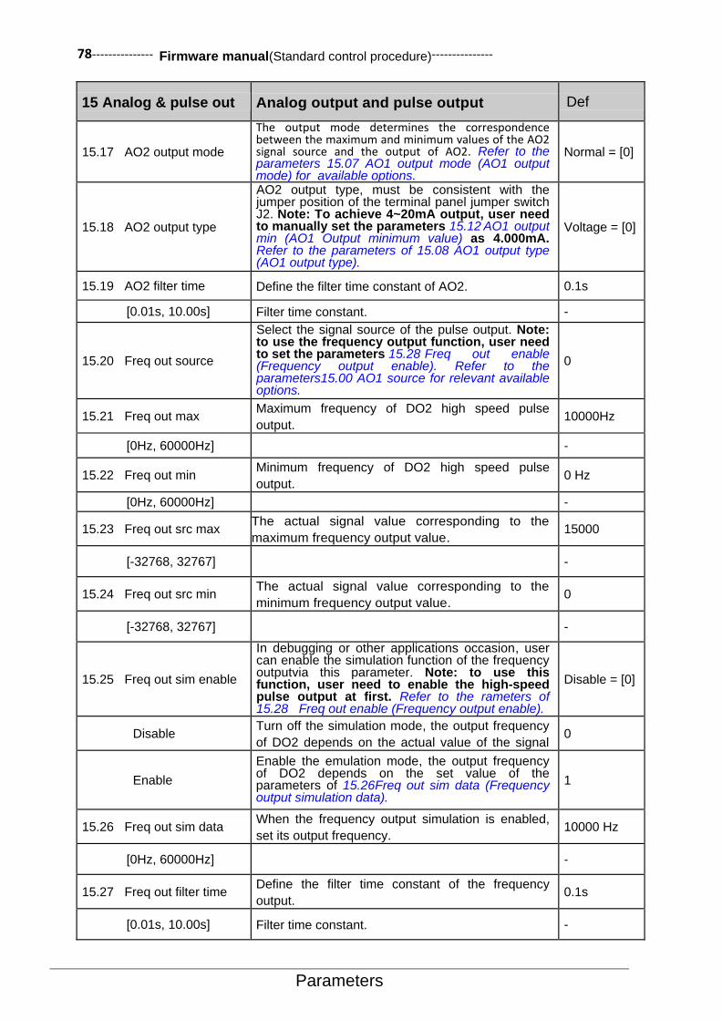
78--------------- Firmware manual(Standard control procedure)---------------
Parameters
15 Analog & pulse out Analog output and pulse output Def
15.17 AO2 output mode
The output mode determines the correspondence between the maximum and minimum values of the AO2 signal source and the output of AO2. Refer to the parameters 15.07 AO1 output mode (AO1 output mode) for available options.
Normal = [0]
15.18 AO2 output type
AO2 output type, must be consistent with the jumper position of the terminal panel jumper switch J2. Note: To achieve 4~20mA output, user need to manually set the parameters 15.12 AO1 output min (AO1 Output minimum value) as 4.000mA. Refer to the parameters of 15.08 AO1 output type (AO1 output type).
Voltage = [0]
15.19 AO2 filter time Define the filter time constant of AO2. 0.1s
[0.01s, 10.00s] Filter time constant. -
15.20 Freq out source
Select the signal source of the pulse output. Note: to use the frequency output function, user need to set the parameters 15.28 Freq out enable (Frequency output enable). Refer to the parameters15.00 AO1 source for relevant available options.
0
15.21 Freq out max Maximum frequency of DO2 high speed pulse
output. 10000Hz
[0Hz, 60000Hz] -
15.22 Freq out min Minimum frequency of DO2 high speed pulse
output. 0 Hz
[0Hz, 60000Hz] -
15.23 Freq out src max The actual signal value corresponding to the
maximum frequency output value. 15000
[-32768, 32767] -
15.24 Freq out src min The actual signal value corresponding to the
minimum frequency output value. 0
[-32768, 32767] -
15.25 Freq out sim enable
In debugging or other applications occasion, user can enable the simulation function of the frequency outputvia this parameter. Note: to use this function, user need to enable the high-speed pulse output at first. Refer to the rameters of 15.28 Freq out enable (Frequency output enable).
Disable = [0]
Disable Turn off the simulation mode, the output frequency
of DO2 depends on the actual value of the signal
source.
0
Enable
Enable the emulation mode, the output frequency of DO2 depends on the set value of the parameters of 15.26Freq out sim data (Frequency output simulation data).
1
15.26 Freq out sim data When the frequency output simulation is enabled,
set its output frequency. 10000 Hz
[0Hz, 60000Hz] -
15.27 Freq out filter time Define the filter time constant of the frequency
output. 0.1s
[0.01s, 10.00s] Filter time constant. -

--------------- Firmware manual(Standard control procedure)--------------- 79
Parameters
15 Analog & pulse out Analog output and pulse output Def
15.28 Freq out enable
DO2 can not only achieve the switch output, but also to achieve the frequency output (i.e. high-speed pulse output), the default is switch output. User can enable the frequency output via this parameter.
Disable = [0]
Disable Frequency output function disabled. 0
Enable Frequency output function enabled. 1
16 System
16 System Drive system settings. Parameter lock, Parameter restore, User parameter setting, etc.
Def
16.00 Local lock Select the signal source of inhibiting local control (LOC/REM button on the control panel). 0: local control permitted, 1: local control inhibited.
CONST.FALSE = [0]
P.01.00.00
User defined pointer (01.00.00 from left to right take two digits as a set, indicates the parameter set, index, and item number in turn. The actual value is determined by the current value of the parameter.)
-
CONST.FALSE Always be 0 0
CONST.TRUE Always be 1 1
DI1 Digital input DI1(02.00 DI state,position 0) 2048
DI2 Digital input DI2 2049
DI3 Digital input DI3 2050
DI4 Digital input DI4 2051
DI5 Digital input DI5 2052
DI6 Digital input DI6 2053
DI7 Digital input DI7 2054
16.01 Parameter lock Select the status of the parameter lock. The parameter lock prevents the parameter from being modified.
Open= [0]
Open Parameter lock open. Parameter values can be modified. 0
Locked Locked. The parameter values cannot be modified from the control keyboard. 1
Not saved Parameters lock open. User can modify the parameter values, but changes will not be saved if the power is cut off.
2
16.02 Pass code Enter different passwords to obtain different parameters access rights. 0
[0, 65535] -
16.03 Param restore Restore the default value of the parameters. This parameter is automatically restored to 0 only after the operation is complete. Affects only the currently active parameter set.
Done= [0]
Done No action or parameter restore completed. 0
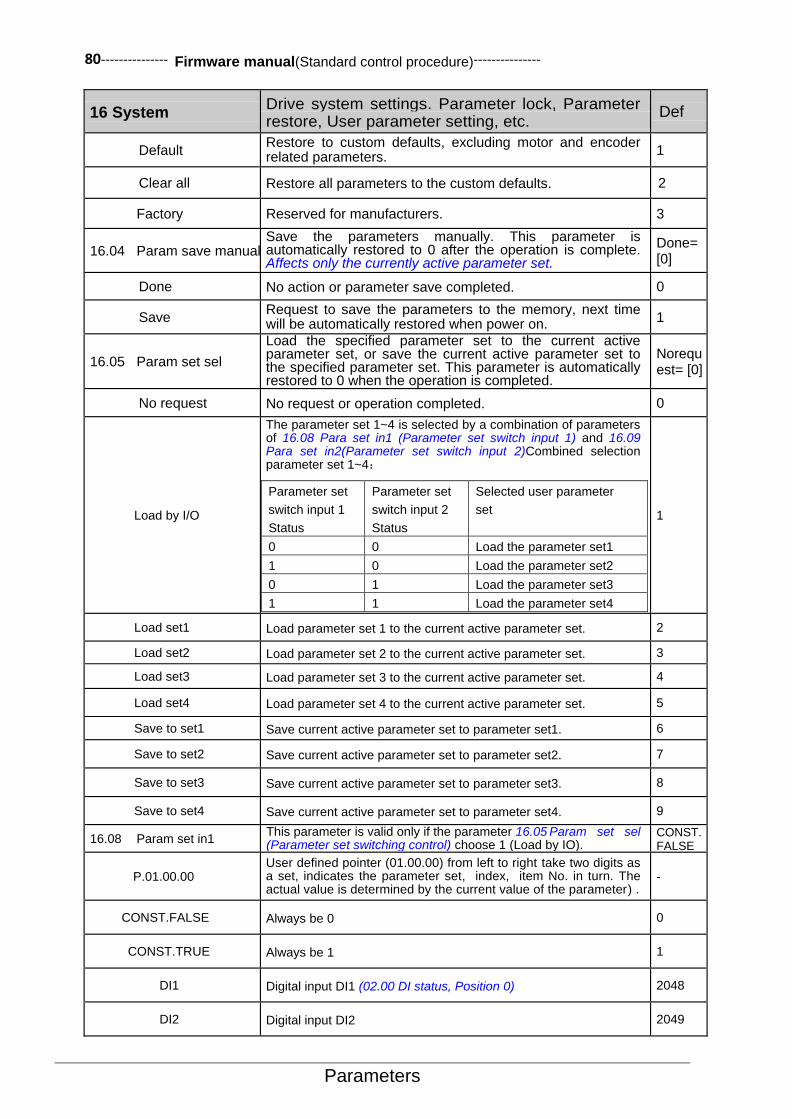
80--------------- Firmware manual(Standard control procedure)---------------
Parameters
16 System Drive system settings. Parameter lock, Parameter restore, User parameter setting, etc.
Def
Default Restore to custom defaults, excluding motor and encoder related parameters.
1
Clear all Restore all parameters to the custom defaults. 2
Factory Reserved for manufacturers. 3
16.04 Param save manual Save the parameters manually. This parameter is automatically restored to 0 after the operation is complete. Affects only the currently active parameter set.
Done= [0]
Done No action or parameter save completed. 0
Save Request to save the parameters to the memory, next time will be automatically restored when power on.
1
16.05 Param set sel
Load the specified parameter set to the current active parameter set, or save the current active parameter set to the specified parameter set. This parameter is automatically restored to 0 when the operation is completed.
Norequest= [0]
No request No request or operation completed. 0
Load by I/O
The parameter set 1~4 is selected by a combination of parameters of 16.08 Para set in1 (Parameter set switch input 1) and 16.09 Para set in2(Parameter set switch input 2)Combined selection parameter set 1~4:
Parameter set
switch input 1
Status
Parameter set
switch input 2
Status
Selected user parameter
set
0 0 Load the parameter set1
1 0 Load the parameter set2
0 1 Load the parameter set3
1 1 Load the parameter set4
1
Load set1 Load parameter set 1 to the current active parameter set. 2
Load set2 Load parameter set 2 to the current active parameter set. 3
Load set3 Load parameter set 3 to the current active parameter set. 4
Load set4 Load parameter set 4 to the current active parameter set. 5
Save to set1 Save current active parameter set to parameter set1. 6
Save to set2 Save current active parameter set to parameter set2. 7
Save to set3 Save current active parameter set to parameter set3. 8
Save to set4 Save current active parameter set to parameter set4. 9
16.08 Param set in1 This parameter is valid only if the parameter 16.05 Param set sel (Parameter set switching control) choose 1 (Load by IO).
CONST.FALSE = [0]
P.01.00.00 User defined pointer (01.00.00) from left to right take two digits as a set, indicates the parameter set, index, item No. in turn. The actual value is determined by the current value of the parameter) .
-
CONST.FALSE Always be 0 0
CONST.TRUE Always be 1 1
DI1 Digital input DI1 (02.00 DI status, Position 0) 2048
DI2 Digital input DI2 2049

--------------- Firmware manual(Standard control procedure)--------------- 81
Parameters
16 System Drive system settings. Parameter lock, Parameter restore, User parameter setting, etc.
Def
DI3 Digital input DI3 2050
DI4 Digital input DI4 2051
DI5 Digital input DI5 2052
DI6 Digital input DI6 2053
DI7 Digital input DI7 2054
16.09 Param set in2
This parameter is valid only when the parameters 16.05 Param set sel (Parameter set switching control) choose 1 (Load by IO). Refer to parameters of 16.08 Param set in1 (Parameter set switching input 1) for relevant available options.
CONST.FALSE = [0]
16.10 Set as default
Set the current value of all parameters to default value. This parameter will automatically restore to 0 when the operation is completed. Refer to parameters of 16.03 Param restore (Parameter recovery).
Done = [0]
Done No request or operation completed. 0
Save as default Request to save the current value of all parameters as custom default value. 1
16.11 Fan on temp Cooling fan turn on temperature value 40.0℃
[0.0, 150.0℃] Fan turn on temperature.
16.12 Fan off temp Cooling fan turn off temperature value. 30.0℃
[0.0, 150.0℃] Fan turn off temperature.
16.13 Fan off delay Delay time of fan off after shutdown when using the
operating signal to control the fan. 30.0s
[0.0, 6553.5s] Fan off delay time.
16.14 Fan ctrl mode Control mode of the cooling fan. Auto = [0]
Auto The fan operates automatically according to the temperature
of the radiator. 0
On while run The fan runs, when drive running. When the drive stops, fan
stops after delay. 1
Always on Fan always run. 2
Always off Fan always stop. Be careful: select this mode may cause
overheating. 3
16.15 System reboot System manual reset request. This parameter is
automatically restored to 0 after the operation is completed.
No request = [0]
No request No request or reset completed. 0
Reboot request Request reset. 1
16.16 System language System language setting. Chinese = [1]
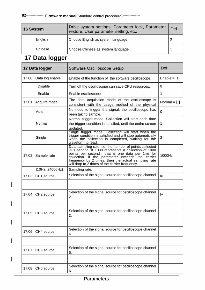
82--------------- Firmware manual(Standard control procedure)---------------
Parameters
16 System Drive system settings. Parameter lock, Parameter restore, User parameter setting, etc.
Def
English Choose English as system language. 0
Chinese Choose Chinese as system language. 1
17 Data logger
17 Data logger Software Oscilloscope Setup Def
17.00 Data log enable Enable of the function of the software oscilloscope. Enable = [1]
Disable Turn off the oscilloscope can save CPU resources. 0
Enable Enable oscilloscope 1
17.01 Acquire mode The data acquisition mode of the oscilloscope is
consistent with the usage method of the physical
oscilloscope.
Normal = [1]
Auto No need to trigger the signal, the oscilloscope has
been taking sample. 0
Normal
Normal trigger mode. Collection will start each time
the trigger condition is satisfied, until the entire screen
updated.
1
Single
Single trigger mode. Collection will start when the trigger condition is satisfied and will stop automatically when the collection is completed, waiting for the waveform to read.
2
17.02 Sample rate
Data sampling rate, i.e. the number of points collected in 1 second. If 1000 represents a collection of 1000 points per second, that is one data per 1ms for collection. If the parameter exceeds the carrier frequency by 2 times, then the actual sampling rate will drop to 2 times of the carrier frequency.
1000Hz
[10Hz, 24000Hz] Sampling rate.
17.03 CH1 source Selection of the signal source for oscilloscope channel
1. Iu
17.04 CH2 source Selection of the signal source for oscilloscope channel
2. Iv
17.05 CH3 source Selection of the signal source for oscilloscope channel
3.
17.06 CH4 source Selection of the signal source for oscilloscope channel
4.
17.07 CH5 source Selection of the signal source for oscilloscope channel
5.
17.08 CH6 source Selection of the signal source for oscilloscope channel
6.

--------------- Firmware manual(Standard control procedure)--------------- 83
Parameters
17 Data logger Software Oscilloscope Setup Def
17.09 CH7 source Selection of the signal source for oscilloscope channel
7.
17.10 CH8 source Selection of the signal source for oscilloscope channel
8.
17.11 Trigger source Selection of the signal source for oscilloscope trigger
channel.
17.12 Force trig Forced trigger request. Done = [0]
Done Completed. 0
Force trig Forced trigger request. 1
17.13 Trig level Set the trigger level. This parameter does not work in
auto- trigger mode. 0
[-32768, 32767] Set trigger level。 -
17.14 Event trig source Select the event triggered signal source. 0: No trigger,
1: trigger.
CONST.FALSE[0]
P.01.00.00
User defined pointer (01.00.00 from left to right take two digits as a set, indicating the parameter group number, Index, Item No. in turn. The actual value is determined by the current value of the parameter.)
-
CONST.FALSE Always be 0 0
CONST.TRUE Always be 1 1
17.15 Trig edge sel
The trigger edge setting, which is used for the signal
source of the trigger, is specified by the parameter of
17.11 Trigger source.
Rising = [0]
Rising Rising edge trigger acquisition. 0
Falling Falling edge trigger acquisition. 1
Both Rising and falling edge trigger acquisition. 2
17.16 Event edge sel
The event edge setting used for trigger is specified by
the parameter of 17.14 Event trig source. Refer to the
parameter 1715 Trig edge sel for relevant available
options.
Rising = [0]
17.17 Channel num
Setting for the number of channels of the oscilloscope. When the number of channels is less than 8, the part of the parameters from 17.03 to 17.10 does not work, by the front is preferred.
6
[1, 8] Channel number setting. -
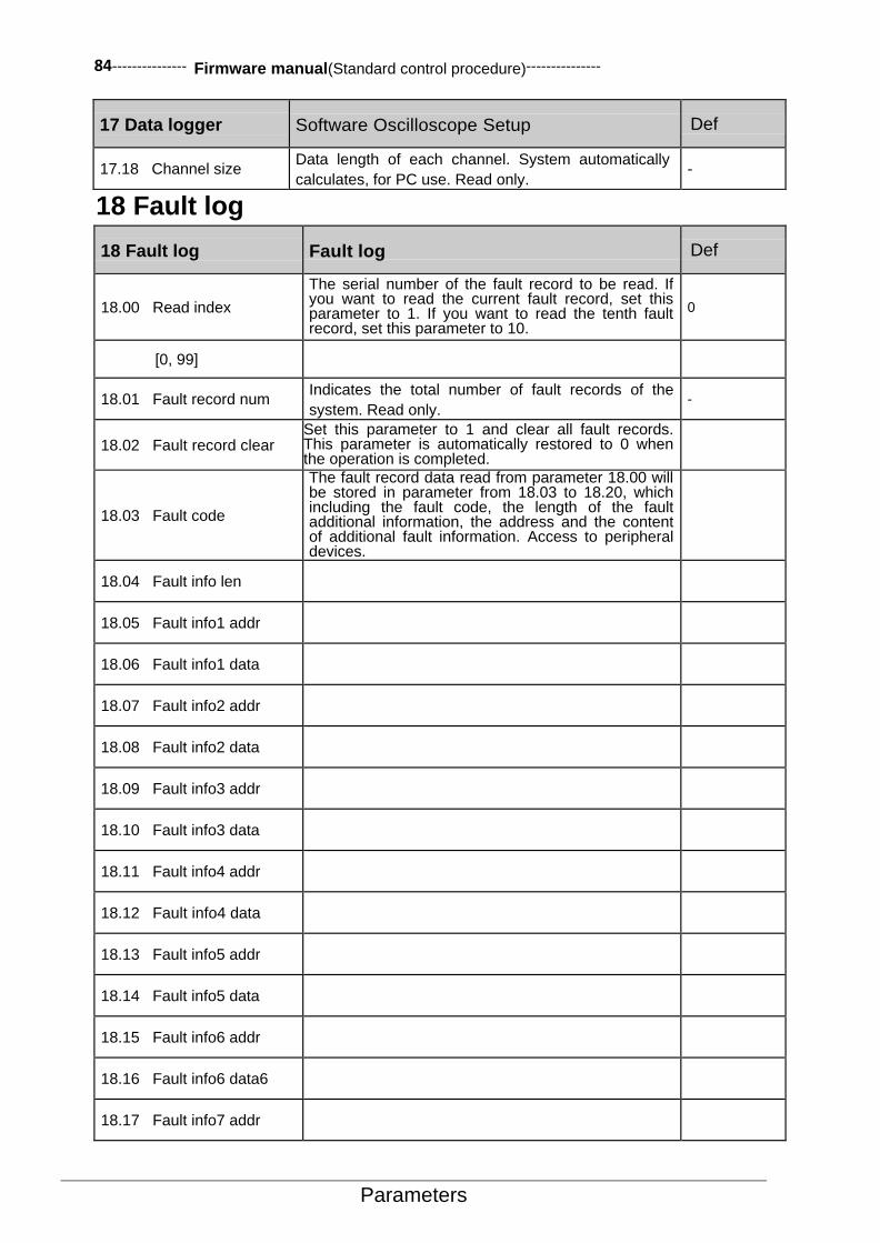
84--------------- Firmware manual(Standard control procedure)---------------
Parameters
17 Data logger Software Oscilloscope Setup Def
17.18 Channel size Data length of each channel. System automatically
calculates, for PC use. Read only. -
18 Fault log
18 Fault log Fault log Def
18.00 Read index
The serial number of the fault record to be read. If you want to read the current fault record, set this parameter to 1. If you want to read the tenth fault record, set this parameter to 10.
0
[0, 99]
18.01 Fault record num Indicates the total number of fault records of the
system. Read only. -
18.02 Fault record clear Set this parameter to 1 and clear all fault records. This parameter is automatically restored to 0 when the operation is completed.
18.03 Fault code
The fault record data read from parameter 18.00 will be stored in parameter from 18.03 to 18.20, which including the fault code, the length of the fault additional information, the address and the content of additional fault information. Access to peripheral devices.
18.04 Fault info len
18.05 Fault info1 addr
18.06 Fault info1 data
18.07 Fault info2 addr
18.08 Fault info2 data
18.09 Fault info3 addr
18.10 Fault info3 data
18.11 Fault info4 addr
18.12 Fault info4 data
18.13 Fault info5 addr
18.14 Fault info5 data
18.15 Fault info6 addr
18.16 Fault info6 data6
18.17 Fault info7 addr

--------------- Firmware manual(Standard control procedure)--------------- 85
Parameters
18 Fault log Fault log Def
18.18 Fault info7 data
18.19 Fault info8 addr
18.20 Fault info8 data
18.21 Fault code 1 The latest first fault code. Read-only.
18.22 Fault code 2 The latest second fault code. Read-only.
18.23 Fault code 3 The latest third fault code. Read-only.
18.24 Fault code 4 The latest fourth fault code. Read-only.
18.25 Fault code 5 The latest fifth fault code. Read-only.
18.26 Fault code 6 The latest sixth fault code. Read-only.
18.27 Fault code 7 The latest seventh fault code. Read-only.
18.28 Fault code 8 The latest eighth fault code. Read-only.
19 Speed Calculation
19 Speed Calculation Speed Calculation Def
19.00 Speed scaling Define the final speed value for acceleration, as well as the initial speed value in deceleration. Similar to the maximum frequency of drives.
1500rpm
[150rpm, 30000rpm]
19.01 Speed filter time Define the filtering time of the speed feedback. 2.0ms
[0.0ms, 10.0ms]
19.02 Zero speed delay Define the zero speed holding time for deceleration
stop. 0.5s
[0.0s, 6000.0s]
19.03 Zero speed level Define the initial speed value of zero speed holding. 30rpm
[0 rpm, 1500rpm]
19.04 Speed window Define the speed window range of the speed to
reach. 30rpm
[0rpm, 1500rpm]

86--------------- Firmware manual(Standard control procedure)---------------
Parameters
20 Limits
20 Limits Limits Control Def
20.00 Maximum speed Define the maximum allowed speed. 1500rpm
[-30000rpm, 30000rpm] Maximum speed.
20.01 Minimum speed Define the minimum allowed speed. -1500rpm
[-30000rpm, 30000rpm] Minimum speed.
20.02 Pos speed enable Select the signal source of the corotation (speed given value is positive) to enable the command. 0: No positive rotation; 1: Allow positive rotation.
CONST.TRUE =[1]
P.01.00.00
User defined pointer (01.00.00 from left to right take two digits as a set, indicating the parameter set, index, item No. in turn. The actual value is determined by the current value of the parameter.)
-
CONST.FALSE Always be 0 0
CONST.TRUE Always be 1 1
DI1 Digital input DI1(02.00 DI State,position 0) 2048
DI2 Digital input DI2 2049
DI3 Digital input DI3 2050
DI4 Digital input DI4 2051
DI5 Digital input DI5 2052
DI6 Digital input DI6 2053
DI7 Digital input DI7 2054
20.03 Neg speed enable
Select the signal source of reverse (the speed
given value is negative) enable command. 0:
reverse inhibited 1: reverse allow. Refer to
parameters 20.02Pos speed enable for relevant
available options.
CONST.TRUE = [1]
20.04 Torque ref max Maximum value of the torque given. Relative to the
rated torque of motor. 150.0%
[0%, 300.0%]
20.05 Torque ref min Minimum value of the torque given. Relative to the
rated torque of motor. -150.0%
[-300.0%, 0%]
20.06 Max motor torque The permitted maximum motor torque. Relative to
the rated torque of motor. 150.0%
[0.0%, 300.0%]
20.07 Max regen torque The permitted maximum generator torque. Relative
to the rated torque of motor. 150.0%

--------------- Firmware manual(Standard control procedure)--------------- 87
Parameters
20 Limits Limits Control Def
[0.0%, 300.0%]
21 Speed Reference
21 Speed Reference Speed Reference Def
21.00 Speed ref1 src Select the signal source for the speed setpoint 1. Also can refer to parameters 21.02 Speedref1 func (Speed given 1 ways).
AI1scaled = [515]
P.01.00
User-defined pointer (01.00 from left to right take two digits a set, indicates the parameter set and the index in turn. The actual value is determined by the current value of the parameter.)
-
Zero Always zero 0
AI1 scaled Refer to parameters 02.03 AI1 scaled (AI1 scaled). 515
AI2 scaled Refer to parameters 02.05 AI2 scaled (AI2 scaled). 517
AI3 scaled Refer to parameters 02.07 AI3 scaled (AI3 scaled). 519
Freq in scaled Refer to parameters 02.11 Freq in scaled (Freq in
scaled). 523
Control panel ref1 Refer to parameters 02.13 Control panel ref1
(Control panel ref 1). 525
Control panel ref2 Refer to parameters 02.14 Control panel ref2
(Control panel ref2). 526
Fieldbus ref1 Refer to parameters 02.15 Fieldbus ref1 (Fieldbus
ref1). 527
Fieldbus ref2 Refer to parameters 02.16 Fieldbus ref2 (Fieldbus
ref2). 528
Motor potent out Refer to parameters 03.01 Motor potent out (Motor
potent out). 769
Const speed out Refer to parameters 03.02 Const speed out (Const speed out).
770
Process PID out Refer to parameters 04.04 Process PID out (Process PID out).
1028
21.01 Speed ref2 src
Select the signal source for the speed setpoint 2.
Refer to parameters 21.00 Speed ref1 src for relevant available options.
AI2 scaled = [517]
21.02 Speed ref1 func
Define the mathematical function of the two reference signal synthesis speed setpoint2 which are selected by the parameters 21.00 Speed ref1 src (Signal source for givenspeed 1) and 21.01 Speed ref2 src (Signal source for givenspeed 2).
Ref1 = [0]
Ref1 The signal selected by the parameter 21.00 Speed ref1src (Signal source for speed given 1) is used as the speed given value1.
0
Add (Ref1 + Ref2)
The sum of the two reference signals is used as
the speed given1. 1
Sub
(Ref1-Ref2)
The difference of the two reference signals is
used as the speed given2. 2
Mul
(Ref1xRef2)
The product of the two reference signals is used
as the speed given3. 3
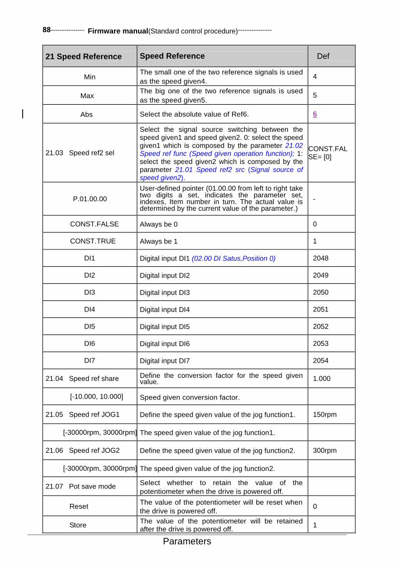
88--------------- Firmware manual(Standard control procedure)---------------
Parameters
21 Speed Reference Speed Reference Def
Min The small one of the two reference signals is used
as the speed given4. 4
Max The big one of the two reference signals is used
as the speed given5. 5
Abs Select the absolute value of Ref6. 6
21.03 Speed ref2 sel
Select the signal source switching between the speed given1 and speed given2. 0: select the speed given1 which is composed by the parameter 21.02 Speed ref func (Speed given operation function); 1: select the speed given2 which is composed by the parameter 21.01 Speed ref2 src (Signal source of speed given2).
CONST.FALSE= [0]
P.01.00.00
User-defined pointer (01.00.00 from left to right take two digits a set, indicates the parameter set, indexes, Item number in turn. The actual value is determined by the current value of the parameter.)
-
CONST.FALSE Always be 0 0
CONST.TRUE Always be 1 1
DI1 Digital input DI1 (02.00 DI Satus,Position 0) 2048
DI2 Digital input DI2 2049
DI3 Digital input DI3 2050
DI4 Digital input DI4 2051
DI5 Digital input DI5 2052
DI6 Digital input DI6 2053
DI7 Digital input DI7 2054
21.04 Speed ref share Define the conversion factor for the speed given value. 1.000
[-10.000, 10.000] Speed given conversion factor.
21.05 Speed ref JOG1 Define the speed given value of the jog function1. 150rpm
[-30000rpm, 30000rpm] The speed given value of the jog function1.
21.06 Speed ref JOG2 Define the speed given value of the jog function2. 300rpm
[-30000rpm, 30000rpm] The speed given value of the jog function2.
21.07 Pot save mode Select whether to retain the value of the
potentiometer when the drive is powered off.
Reset The value of the potentiometer will be reset when
the drive is powered off. 0
Store The value of the potentiometer will be retained after the drive is powered off.
1

--------------- Firmware manual(Standard control procedure)--------------- 89
Parameters
21 Speed Reference Speed Reference Def
21.08 Pot up source
Select the incremental instruction signal source of the electric potentiometer. 0: No incremental instruction; 1: Has incremental instruction. Refer to parameters 21.03 Speed ref2 sel for relevant available options.
CONST.FALSE= [0]
21.09 Pot down source
Select the descending instruction signal source of the electric potentiometer. 0: No descending instruction; 1: Has descending instruction. Refer to parameters 21.03 Speed ref2 sel for relevant available options.
CONST.FALSE= [0]
21.10 Pot output max The maximum output of the electric potentiometer. 1500rpm
[0, 30000rpm]
21.11 Pot output min The minimum output of the electric potentiometer. -1500rpm
[-30000rpm, 0rpm]
21.12 Pot ramp time The acceleration and deceleration time from the parameter 21.10 to 21.11 for the output of the electric potentiometer.
10.0s
[0.1s, 100.0s]
21.13 Pot output The real-time output of the electric potentiometer.
Read-only.
21.14 Slow down spd ref Up or down speed limits value. 301rpm
[0, 30000]
21.15 Up slow rqst Signal source selection of the up deceleration
request.
CONST TRUE
21.16 Down slow rqst Signal source selection of the down deceleration
request.
CONST TRUE
22 Speed Ramp(Speed Given Ramp Generator)
22 Speed Ramp Speed Given Ramp Generator Def
22.00 Acc time1
Define the acceleration time 1, as the time required for the speed to accelerate from zero to the parameters 19.00 Speed scaling (velocity reference value) defined value. If the speed of the given signal growth rate is faster than the rate of the acceleration, the motor speed will follow the acceleration rate. If the speed of the given signal growth rate is slower than the set acceleration rate, the motor speed will follow the given signal changes. If acceleration time set too short, the driver will be automatically extended acceleration time, in order to prevent the acceleration current exceeds the set value of the drive torque limit value in the speed up process.
Model correlation
[0.01s, 655.35s]
22.01 Dec time1 Deceleration time1 Model dependent
[0.01s, 655.35s]
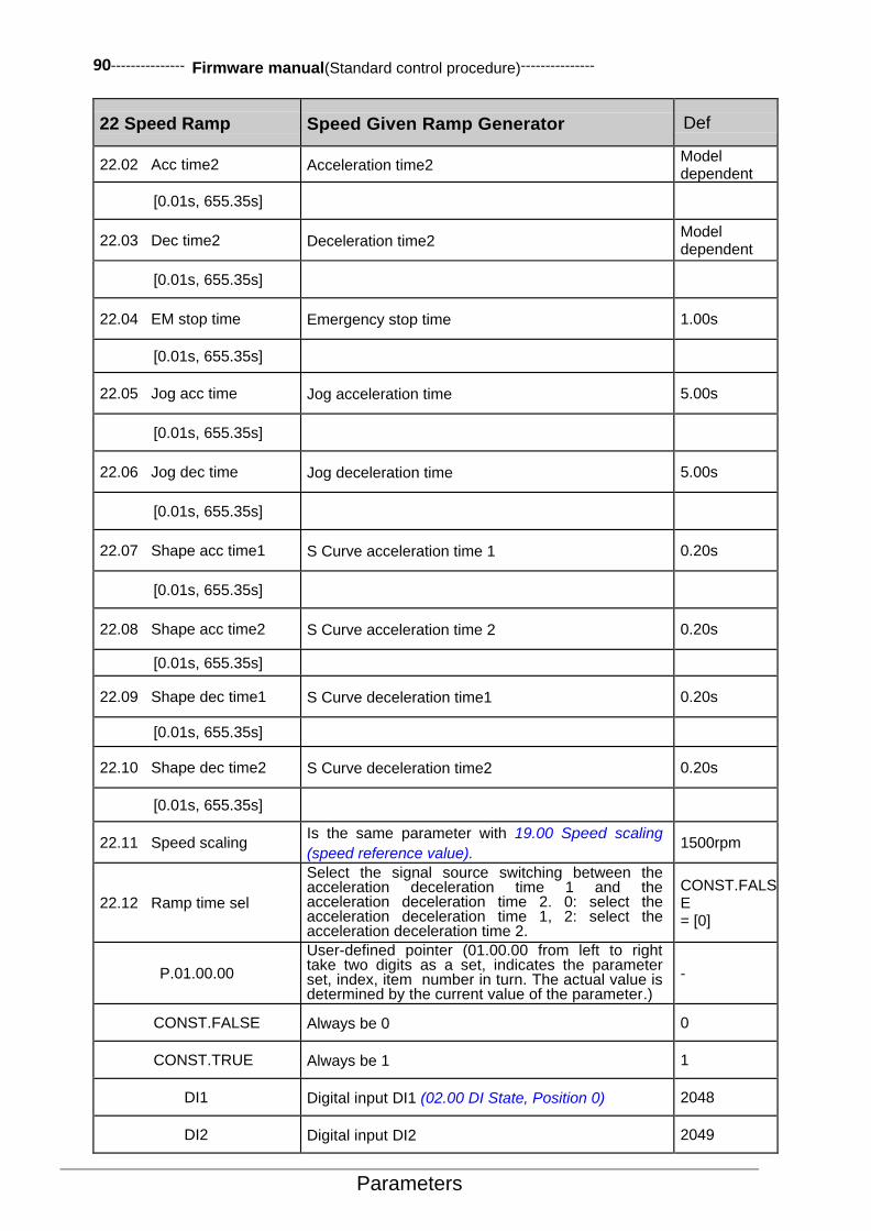
90--------------- Firmware manual(Standard control procedure)---------------
Parameters
22 Speed Ramp Speed Given Ramp Generator Def
22.02 Acc time2 Acceleration time2 Model dependent
[0.01s, 655.35s]
22.03 Dec time2 Deceleration time2 Model dependent
[0.01s, 655.35s]
22.04 EM stop time Emergency stop time 1.00s
[0.01s, 655.35s]
22.05 Jog acc time Jog acceleration time 5.00s
[0.01s, 655.35s]
22.06 Jog dec time Jog deceleration time 5.00s
[0.01s, 655.35s]
22.07 Shape acc time1 S Curve acceleration time 1 0.20s
[0.01s, 655.35s]
22.08 Shape acc time2 S Curve acceleration time 2 0.20s
[0.01s, 655.35s]
22.09 Shape dec time1 S Curve deceleration time1 0.20s
[0.01s, 655.35s]
22.10 Shape dec time2 S Curve deceleration time2 0.20s
[0.01s, 655.35s]
22.11 Speed scaling Is the same parameter with 19.00 Speed scaling
(speed reference value). 1500rpm
22.12 Ramp time sel
Select the signal source switching between the acceleration deceleration time 1 and the acceleration deceleration time 2. 0: select the acceleration deceleration time 1, 2: select the acceleration deceleration time 2.
CONST.FALSE = [0]
P.01.00.00
User-defined pointer (01.00.00 from left to right take two digits as a set, indicates the parameter set, index, item number in turn. The actual value is determined by the current value of the parameter.)
-
CONST.FALSE Always be 0 0
CONST.TRUE Always be 1 1
DI1 Digital input DI1 (02.00 DI State, Position 0) 2048
DI2 Digital input DI2 2049

--------------- Firmware manual(Standard control procedure)--------------- 91
Parameters
22 Speed Ramp Speed Given Ramp Generator Def
DI3 Digital input DI3 2050
DI4 Digital input DI4 2051
DI5 Digital input DI5 2052
DI6 Digital input DI6 2053
DI7 Digital input DI7 2054
23 Speed Control
23 Speed Control Speed Control Def
23.00 Speed Kp
Define the proportional gain of the speed controller
(Kp). The excessive gain may cause speed
oscillation.
1.00
[0.00, 30.00]
23.01 Speed Ti Set the integral time of the speed loop. 60ms
[0, 3000ms]
23.02 Torque Kp Set the proportional gain of the torque loop. 1.00
[0.00, 30.00]
23.03 Droop rate Speed droop control rate used for speed droop
control only. 0.0%
[0.0, 1000.0%]
24 Torque Reference
24 Torque Reference Torque Reference Def
24.00 Torque ref1 src Select the signal source of torque given value 1. AI1scaled = [515]
P.01.00
User-defined pointer (01.00 from left to right take two digits as a set, indicates the parameter set, indexes in turn. The actual value is determined by the current value of the parameter.)
-
Zero Always zero 0
AI1 scaled Refer to parameters of 02.03 AI1 scaled
(AI1scaled). 515
AI2 scaled Refer to parameters of 02.05 AI2 scaled
(AI2scaled). 517
AI3 scaled Refer to parameters of 02.07 AI3 scaled
(AI3scaled). 519
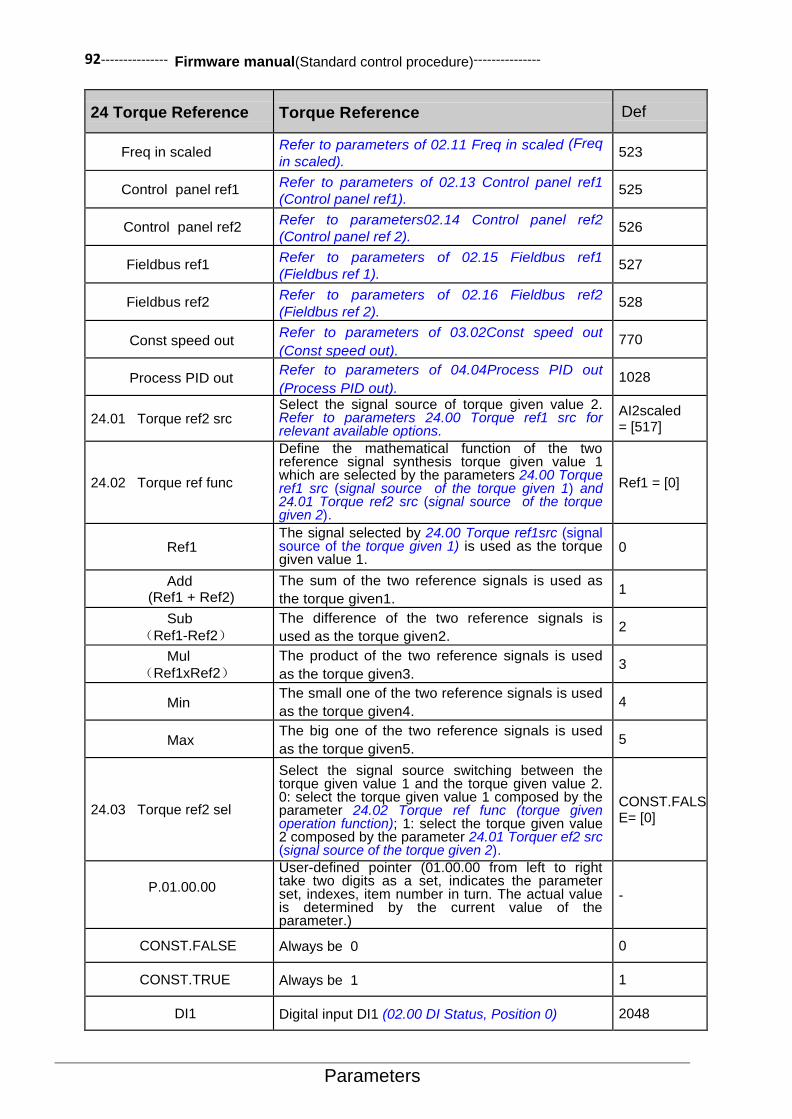
92--------------- Firmware manual(Standard control procedure)---------------
Parameters
24 Torque Reference Torque Reference Def
Freq in scaled Refer to parameters of 02.11 Freq in scaled (Freq
in scaled). 523
Control panel ref1 Refer to parameters of 02.13 Control panel ref1
(Control panel ref1). 525
Control panel ref2 Refer to parameters02.14 Control panel ref2
(Control panel ref 2). 526
Fieldbus ref1 Refer to parameters of 02.15 Fieldbus ref1
(Fieldbus ref 1). 527
Fieldbus ref2 Refer to parameters of 02.16 Fieldbus ref2
(Fieldbus ref 2). 528
Const speed out Refer to parameters of 03.02Const speed out
(Const speed out). 770
Process PID out Refer to parameters of 04.04Process PID out
(Process PID out). 1028
24.01 Torque ref2 src Select the signal source of torque given value 2. Refer to parameters 24.00 Torque ref1 src for relevant available options.
AI2scaled = [517]
24.02 Torque ref func
Define the mathematical function of the two reference signal synthesis torque given value 1 which are selected by the parameters 24.00 Torque ref1 src (signal source of the torque given 1) and 24.01 Torque ref2 src (signal source of the torque given 2).
Ref1 = [0]
Ref1 The signal selected by 24.00 Torque ref1src (signal source of the torque given 1) is used as the torque given value 1.
0
Add (Ref1 + Ref2)
The sum of the two reference signals is used as
the torque given1. 1
Sub
(Ref1-Ref2)
The difference of the two reference signals is
used as the torque given2. 2
Mul
(Ref1xRef2)
The product of the two reference signals is used
as the torque given3. 3
Min The small one of the two reference signals is used
as the torque given4. 4
Max The big one of the two reference signals is used
as the torque given5. 5
24.03 Torque ref2 sel
Select the signal source switching between the torque given value 1 and the torque given value 2. 0: select the torque given value 1 composed by the parameter 24.02 Torque ref func (torque given operation function); 1: select the torque given value 2 composed by the parameter 24.01 Torquer ef2 src (signal source of the torque given 2).
CONST.FALSE= [0]
P.01.00.00
User-defined pointer (01.00.00 from left to right take two digits as a set, indicates the parameter set, indexes, item number in turn. The actual value is determined by the current value of the parameter.)
-
CONST.FALSE Always be 0 0
CONST.TRUE Always be 1 1
DI1 Digital input DI1 (02.00 DI Status, Position 0) 2048
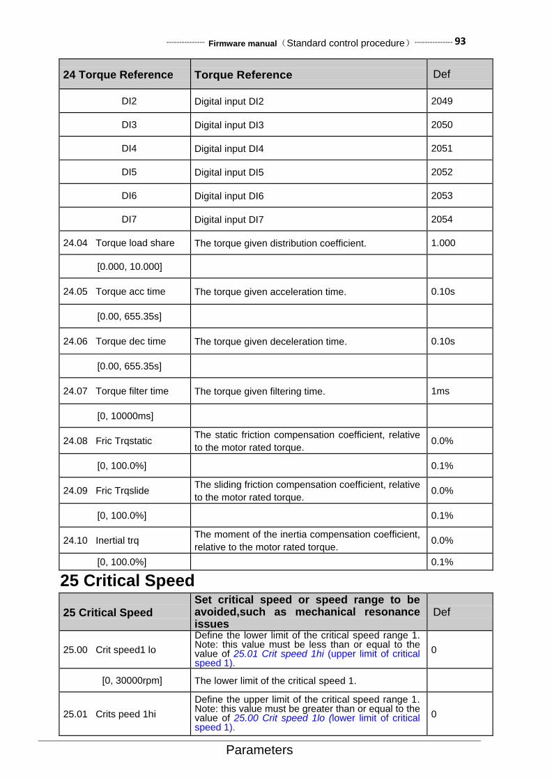
--------------- Firmware manual(Standard control procedure)--------------- 93
Parameters
24 Torque Reference Torque Reference Def
DI2 Digital input DI2 2049
DI3 Digital input DI3 2050
DI4 Digital input DI4 2051
DI5 Digital input DI5 2052
DI6 Digital input DI6 2053
DI7 Digital input DI7 2054
24.04 Torque load share The torque given distribution coefficient. 1.000
[0.000, 10.000]
24.05 Torque acc time The torque given acceleration time. 0.10s
[0.00, 655.35s]
24.06 Torque dec time The torque given deceleration time. 0.10s
[0.00, 655.35s]
24.07 Torque filter time The torque given filtering time. 1ms
[0, 10000ms]
24.08 Fric Trqstatic The static friction compensation coefficient, relative
to the motor rated torque. 0.0%
[0, 100.0%] 0.1%
24.09 Fric Trqslide The sliding friction compensation coefficient, relative
to the motor rated torque. 0.0%
[0, 100.0%] 0.1%
24.10 Inertial trq The moment of the inertia compensation coefficient,
relative to the motor rated torque.
relative motor rated torque。
0.0%
[0, 100.0%] 0.1%
25 Critical Speed
25 Critical Speed Set critical speed or speed range to be avoided,such as mechanical resonance issues
Def
25.00 Crit speed1 lo
Define the lower limit of the critical speed range 1. Note: this value must be less than or equal to the value of 25.01 Crit speed 1hi (upper limit of critical speed 1).
0
[0, 30000rpm] The lower limit of the critical speed 1.
25.01 Crits peed 1hi
Define the upper limit of the critical speed range 1. Note: this value must be greater than or equal to the value of 25.00 Crit speed 1lo (lower limit of critical speed 1).
0

94--------------- Firmware manual(Standard control procedure)---------------
Parameters
25 Critical Speed Set critical speed or speed range to be avoided,such as mechanical resonance issues
Def
[0, 30000rpm] The upper limit of the critical speed 1.
25.02 Crit speed 2lo
Define the lower limit of the critical speed range 2. Note: this value must be less than or equal to the value of 25.03 Crit speed 2hi (upper limit of critical speed 2).
0
[0, 30000rpm] The lower limit of the critical speed 2.
25.03 Crit speed 2hi
Define the upper limit of the critical speed range 2. Note: this value must be greater than or equal to the value of 25.02 Crit speed 2lo (lower limit of critical speed2).
0
[0, 30000rpm] The upper limit of the critical speed 2.
25.04 Crits peed 3lo
Define the lower limit of the critical speed range 3. Note: this value must be less than or equal to the value of 25.05 Crit speed 3hi (upper limit of critical speed 3).
0
[0, 30000rpm] The lower limit of the critical speed 3.
25.05 Critspeed3hi
Define the upper limit of the critical speed range 3.
Note: this value must be greater than or equal to the
value of 25.04 Crit speed 3lo (lower limit of critical
speed 3).
0
[0, 30000rpm] The upper limit of the critical speed 3.
25.06 Critspeedsel Critical speed control Disable= [0]
Disable Disable critical speed control. 0
Enable Enable critical speed control. 1
26 Constant Speeds (Multi-speeds) 26 Constant
Speeds Selection and value of multi segment velocity Def
26.00 Const speed0
Define the multi segment speed 0. 750 rpm
[-30000rpm, 30000rpm]
Multi segment speed 0.
26.01 Const speed1
Define the multi segment speed 1. For the value range and units and other instructions refer to the parameter 26.00 Const speed0 (Const speed1).
1500 rpm
26.02 Const speed2
Define the multi segment speed 2. For the value range and units and other instructions refer to the parameter 26.00 Const speed0 (Const speed1).
1500 rpm
26.03 Const speed3
Define the multi segment speed 3. For the value range and units and other instructions refer to the parameter 26.00 Const speed0 (Const speed1).
1500 rpm
26.04 Const speed4
Define the multi segment speed 4. For the value range and units and other instructions refer to the parameter 26.00 Const speed0 (Const speed1).
1500 rpm
26.05 Const speed5
Define the multi segment speed 5. For the value range and units and other instructions refer to the parameter 26.00 Const speed0 (Const speed1).
0 rpm
26.06 Const speed6
Define the multi segment speed 6. For the value range and units and other instructions refer to the parameter 26.00 Const speed0 (Const speed1).
0 rpm
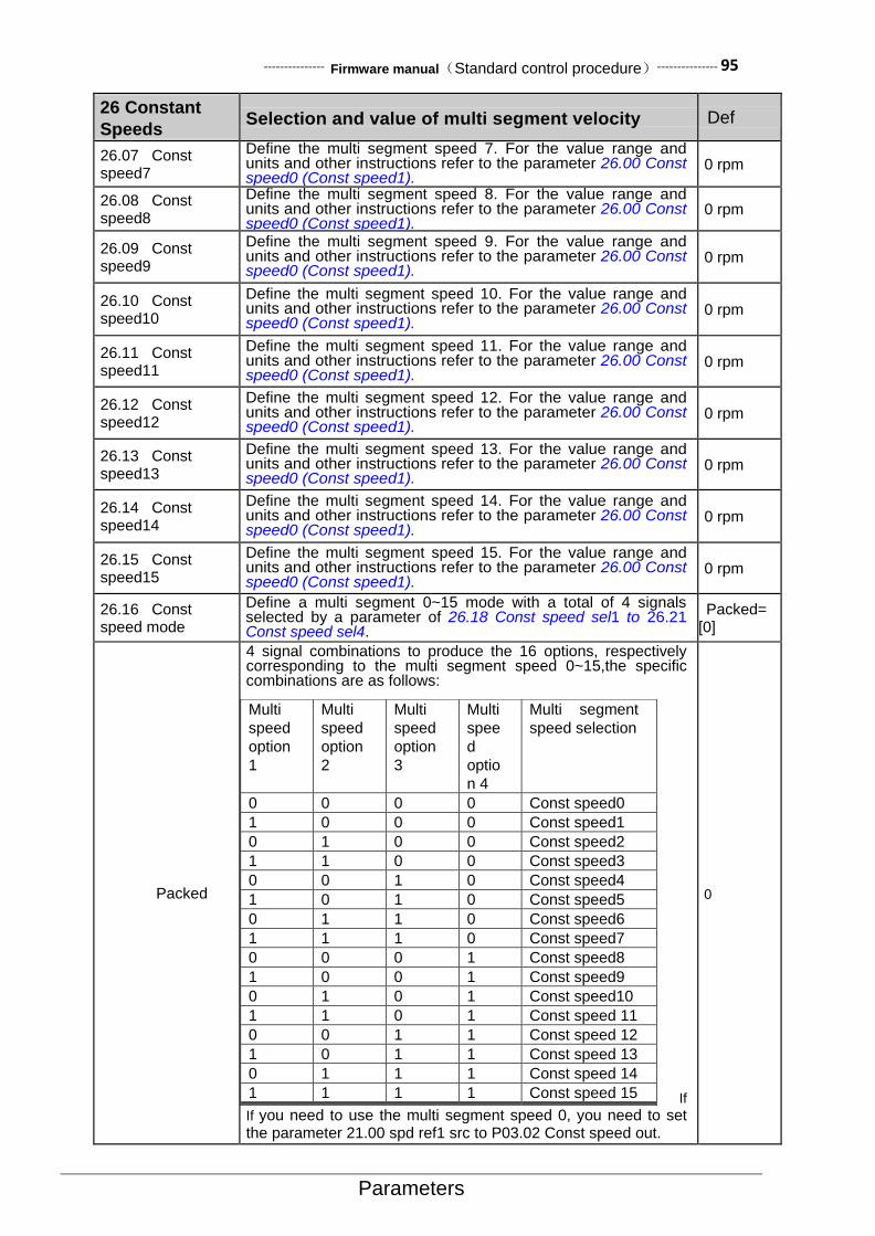
--------------- Firmware manual(Standard control procedure)--------------- 95
Parameters
26 Constant
Speeds Selection and value of multi segment velocity Def
26.07 Const speed7
Define the multi segment speed 7. For the value range and units and other instructions refer to the parameter 26.00 Const speed0 (Const speed1).
0 rpm
26.08 Const speed8
Define the multi segment speed 8. For the value range and units and other instructions refer to the parameter 26.00 Const speed0 (Const speed1).
0 rpm
26.09 Const speed9
Define the multi segment speed 9. For the value range and units and other instructions refer to the parameter 26.00 Const speed0 (Const speed1).
0 rpm
26.10 Const speed10
Define the multi segment speed 10. For the value range and units and other instructions refer to the parameter 26.00 Const speed0 (Const speed1).
0 rpm
26.11 Const speed11
Define the multi segment speed 11. For the value range and units and other instructions refer to the parameter 26.00 Const speed0 (Const speed1).
0 rpm
26.12 Const speed12
Define the multi segment speed 12. For the value range and units and other instructions refer to the parameter 26.00 Const speed0 (Const speed1).
0 rpm
26.13 Const speed13
Define the multi segment speed 13. For the value range and units and other instructions refer to the parameter 26.00 Const speed0 (Const speed1).
0 rpm
26.14 Const speed14
Define the multi segment speed 14. For the value range and units and other instructions refer to the parameter 26.00 Const speed0 (Const speed1).
0 rpm
26.15 Const speed15
Define the multi segment speed 15. For the value range and units and other instructions refer to the parameter 26.00 Const speed0 (Const speed1).
0 rpm
26.16 Const speed mode
Define a multi segment 0~15 mode with a total of 4 signals selected by a parameter of 26.18 Const speed sel1 to 26.21 Const speed sel4.
Packed= [0]
Packed
4 signal combinations to produce the 16 options, respectively corresponding to the multi segment speed 0~15,the specific combinations are as follows:
If
If you need to use the multi segment speed 0, you need to set the parameter 21.00 spd ref1 src to P03.02 Const speed out.
Multi
speed
option
1
Multi
speed
option
2
Multi
speed
option
3
Multi
spee
d
optio
n 4
Multi segment
speed selection
0 0 0 0 Const speed0
1 0 0 0 Const speed1
0 1 0 0 Const speed2
1 1 0 0 Const speed3
0 0 1 0 Const speed4
1 0 1 0 Const speed5
0 1 1 0 Const speed6
1 1 1 0 Const speed7
0 0 0 1 Const speed8
1 0 0 1 Const speed9
0 1 0 1 Const speed10
1 1 0 1 Const speed 11
0 0 1 1 Const speed 12
1 0 1 1 Const speed 13
0 1 1 1 Const speed 14
1 1 1 1 Const speed 15
1 0 1 1 多段速 14
0 1 1 1 多段速 15 1 1 1 1 多段速 16
0

96--------------- Firmware manual(Standard control procedure)---------------
Parameters
26 Constant
Speeds Selection and value of multi segment velocity Def
Separate
The 4 signals are used to select the multi segment speed 0~4, among which the priority of the multi segment speed 4 is the highest, and the priority of the multi segment speed 1 is the lowest.. The specific correspondence is as follows:
Multi
speed
option1
Multi
speed
option2
Multi
speed
option3
Multi
speed
option4
Multi segment
speed
selection
0 0 0 0 Const speed0
1 x0 x0 x0 Const speed1
x0 1 x0 x0 Const speed2
x0 x0 1 x0 Const speed3
x0 x0 x0 1 Const speed4
If you need to use the multi segment speed 0, you need to set
the parameter 21.00 spd ref1 src to P03.02 Const speed out.
1
26.17 Const speed out
Output of the multi segment speed. 0 rpm
[-30000rpm, 30000rpm]
Actual output of the multi speed. Read-only.
26.18 Const speed sel1
Signal source of the multi segment speed selection 1. Note: the usage method of the multi segment speed selection 1~4 refer to the parameters 26.16 Constspeed mode (Multi speed mode).
CONST.FALSE= [0]
P.01.00.00
User-defined pointer (01.00.00 from left to right take two digits
as a set, indicates the parameter set, indexes, item number in
turn. The actual value is determined by the current value of the
parameter)
-
CONST.FALSE Always be 0 0
CONST.TRUE Always be 1 1
DI1 Digital input DI1 (02.00 DI Status, Position 0) 2048
DI2 Digital input DI2 2049
DI3 Digital input DI3 2050
DI4 Digital input DI4 2051
DI5 Digital input DI5 2052
DI6 Digital input DI6 2053
DI7 Digital input DI7 2054
26.19 Const speed sel2
Signal source of the multi segment speed selection 2.
Refer to parameters 26.18 Const speed sel1 for relevant
available options.
CONST.FALSE= [0]
26.20 Const speed sel3
Signal source of the multi segment speed selection 3.
Refer to parameters 26.18 Const speed sel1 for relevant
available options.
CONST.FALSE= [0]

--------------- Firmware manual(Standard control procedure)--------------- 97
Parameters
26 Constant
Speeds Selection and value of multi segment velocity Def
26.21 Const speed sel4
Signal source of the multi segment speed selection 4.
Refer to parameters 26.18 Const speed sel1 for relevant
available options.
CONST.FALSE= [0]
27 Process PID
27 Process PID PID for Process Control Def
27.00 PID activate Active the control of the process control PID. Disable = [0]
Disable Process control disabled. 0
Enable Process control activated. 1
27.01 Reference source Select a given signal source. P.27.02 = [6914]
P.01.00
User-defined pointer (01.00 from left to right take two digits as a set, indicates the parameter set, index in turn. The actual value is determined by the current value of the parameter.)
-
Zero Always zero 0
AI1 scaled Refer to parameters of 02.03 AI1 scaled (AI1
scaled). 515
AI2 scaled Refer to parameters of 02.05 AI2 scaled (AI2
scaled). 517
AI3 scaled Refer to parameters of 02.07 AI3 scaled (AI3
scaled). 519
Freq in scaled Refer to parameters of 02.11 Freq in scaled (Freq
in scaled). 523
Control panel ref1 Refer to parameters of 02.13 Control panel ref1
(Control panel ref 1). 525
Control panel ref2 Refer to parameters of 02.14 Control panel ref2
(Control panel ref 2). 526
Fieldbus ref1 Refer to parameters 02.15 Fieldbus ref1 (Fieldbus
ref 1). 527
Fieldbus ref2 Refer to parameters 02.16 Fieldbus ref2 (Fieldbus
ref 2). 528
27.02 Ref internal Internal digital given for process control. 0
[-32768, 32767]
27.03 Ref filter time Given filter time constant. 0.1s
[0.01s, 3.00s] Filter time constant. -
27.04 Reference actual Given actual value. Read-only.
27.05 Feedback func Select the operation mode of feedback signal
source 1 and feedback signal source 2. Fbk1 = [0]

98--------------- Firmware manual(Standard control procedure)---------------
Parameters
27 Process PID PID for Process Control Def
Fbk1 Select feedback 1 as the actual feedback of PID. 0
Add Select feedback 1 plus feedback 2 as actual
feedback. 1
Sub Select feedback 1 minus feedback 2 as actual
feedback. 2
Min Select the small value of feedback 1 and feedback 2
as feedback. 3
Max Select the big value of feedback 1 and feedback 2
as feedback. 4
27.06 Feedback 1 source Select the signal source of feedback 1. Refer to parameters 27.01 Reference source (given signal source) for relevant available options.
AI1 scaled = [515]
27.07 Feedback 2 source Select the signal source of feedback 2. Refer to parameters 27.01 Reference source (given signal source) for relevant available options.
AI2 scaled = [517]
27.08 Feedback1 max Set the maximum allowable value of feedback 1. 32767
[-32768, 32767]
27.09 Feedback1 min Set the minimum allowable value of feedback 1. -32768
[-32768, 32767]
27.10 Feedback2 max Set the maximum allowable value of feedback 2. 32767
[-32768, 32767]
27.11 Feedback2 min Set the minimum allowable value of feedback 2. -32768
[-32768, 32767]
27.12 Feedback gain Feedback gain factor. 1.00
[0.10, 10.00]
27.13 Fbk filter time Filter time constant of the feedback. 0.01s
[0.01s, 2.00s]
27.14 Feedback actual Actual value of the feedback. Read-only.
27.15 PID Kp Proportional gain of PID 1.00
[0.01, 100.00]
27.16 PID Ti PID integration time. 1.00s
[0.10s, 20.00s]

--------------- Firmware manual(Standard control procedure)--------------- 99
Parameters
27 Process PID PID for Process Control Def
27.17 PID Td PID differential time. 0.00s
[0.00s, 20.00s]
27.18 Deriv filter time Filtering time of differential quantity. 1.00s
[0.01s, 20.00s]
27.19 Error invert sel Error is selected by the reverse mode. Disable = [0]
Disable Disable reverse,i.e. the feedback increases,output
decreases. 0
Enable Enable reverse. i.e. the feedback increases, the
output also increases. 1
27.20 output trim mode Format the output. Direct = [1]
Direct The output is not converted. 0
Speed The output is converted into the speed dimension. 1
Torque The output is converted into the torque dimension. 2
27.21 Out max The maximum allowable value of PID output. 1500
[-32768, 32767]
27.22 Out min The minimum allowable value of PID output. -1500
[-32768, 32767]
27.23 Bal enable sel Balanced control enable signal. Disable = [0]
Disable Balance control disable. 0
Enable Balance control enabled. 1
27.24 Bal ref Qualification of balance control. 0
[-32768, 32767]
27.25 Sleep mode Hiberation mode. No sleep= [0]
No sleep Process control never goes to hiberation mode. 0
Sleep internal Process control enable hiberation externally. 1
Sleep external
Process control enable hiberation by external signal,
and will be triggered when the actual speed is less
than the value of the following clause of 27.26.
2

100--------------- Firmware manual(Standard control procedure)---------------
Parameters
27 Process PID PID for Process Control Def
Sleep by error Enable hiberation when the deviation is less than
the value of the following clause of 27.28. 3
27.26 Sleep level Motor speed level triggered by PID hiberation. 900
[-32768, 32767]
27.27 Sleep delay Delay time of PID hiberation. 60.0s
[0.0, 6553.5s]
27.28 Wakeup level The error level of PID wake up. Wake up when the
PID error is greater than the value. 1000
[-32768, 32767]
27.29 Wakeup delay PID wake up delay time after hiberation. 1.0s
[0.0, 6553.5s]
27.30 Sleep enable sel Selection of PID sleep external enable signal
source. Bit pointer.
CONST.FALSE= [0]
P.01.00.00
User-defined pointer (01.00.00 from left to right take two digits as a set, indicates the parameter set, index, item number in turn. The actual value is determined by the current value of the parameter.)
-
CONST.FALSE Always be 0. 0
CONST.TRUE Always be 1. 1
DI1 Digital input DI1 (02.00 DI Status, Position 0) 2048
DI2 Digital input DI2 2049
DI3 Digital input DI3 2050
DI4 Digital input DI4 2051
DI5 Digital input DI5 2052
DI6 Digital input DI6 2053
DI7 Digital input DI7 2054
27.31 Calc enable sel Select the signal source of PID operation enable. Running = [6148]
P.01.00.00
User-defined pointer (01.00.00 from left to right take two digits as a set, indicates the parameter set, index, item number in turn. The actual value is determined by the current value of the parameter.)
-
CONST.FALSE Always be 0 0
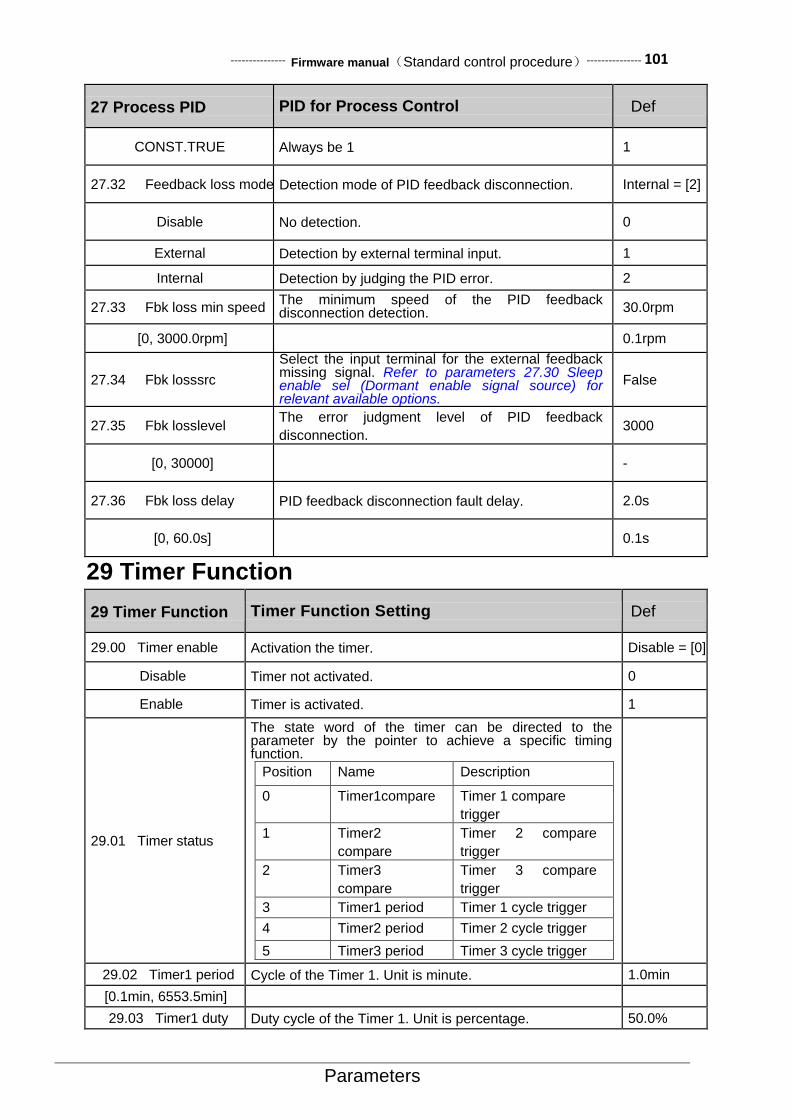
--------------- Firmware manual(Standard control procedure)--------------- 101
Parameters
27 Process PID PID for Process Control Def
CONST.TRUE Always be 1 1
27.32 Feedback loss mode Detection mode of PID feedback disconnection. Internal = [2]
Disable No detection. 0
External Detection by external terminal input. 1
Internal Detection by judging the PID error. 2
27.33 Fbk loss min speed The minimum speed of the PID feedback disconnection detection. 30.0rpm
[0, 3000.0rpm] 0.1rpm
27.34 Fbk losssrc
Select the input terminal for the external feedback missing signal. Refer to parameters 27.30 Sleep enable sel (Dormant enable signal source) for relevant available options.
False
27.35 Fbk losslevel The error judgment level of PID feedback
disconnection. 3000
[0, 30000] -
27.36 Fbk loss delay PID feedback disconnection fault delay. 2.0s
[0, 60.0s] 0.1s
29 Timer Function
29 Timer Function Timer Function Setting Def
29.00 Timer enable Activation the timer. Disable = [0]
Disable Timer not activated. 0
Enable Timer is activated. 1
29.01 Timer status
The state word of the timer can be directed to the parameter by the pointer to achieve a specific timing function.
Position Name Description
0 Timer1compare Timer 1 compare
trigger
1 Timer2
compare
Timer 2 compare
trigger
2 Timer3
compare
Timer 3 compare
trigger
3 Timer1 period Timer 1 cycle trigger
4 Timer2 period Timer 2 cycle trigger
5 Timer3 period Timer 3 cycle trigger
29.02 Timer1 period Cycle of the Timer 1. Unit is minute. 1.0min
[0.1min, 6553.5min]
29.03 Timer1 duty Duty cycle of the Timer 1. Unit is percentage. 50.0%

102--------------- Firmware manual(Standard control procedure)---------------
Parameters
29 Timer Function Timer Function Setting Def
[0.0%, 100.0%]
29.04 Timer2 period Cycle of the Timer 2. Unit is minute. 1.0min
[0.1min, 6553.5min]
29.05 Timer2 duty Duty cycle of the Timer 2. Unit is percentage. 50.0%
[0.0%, 100.0%]
29.06 Timer3 period Cycle of the Timer 3. Unit is minute. 1.0min
[0.1min, 6553.5min]
29.07 Timer3 duty Duty cycle of the Timer 3. Unit is percentage. 50.0%
[0.0%, 100.0%]
29.08 long period For long cycle mode, the unit of the timer cycle is minute;
for short cycle mode, the unit of the timer cycle is second. Disable
Disable Short cycle mode, Second. 0
Enable Long cycle mode, Minute. 1
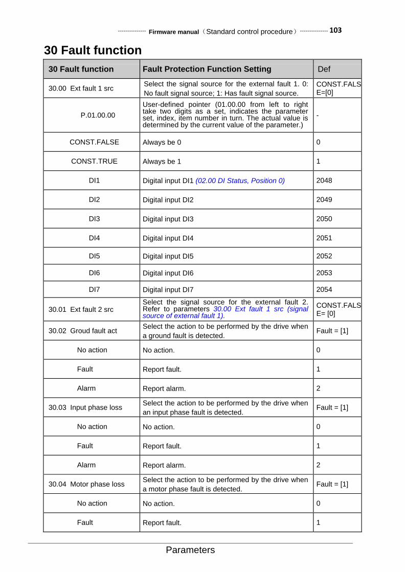
--------------- Firmware manual(Standard control procedure)--------------- 103
Parameters
30 Fault function
30 Fault function Fault Protection Function Setting Def
30.00 Ext fault 1 src Select the signal source for the external fault 1. 0:
No fault signal source; 1: Has fault signal source.
CONST.FALSE=[0]
P.01.00.00
User-defined pointer (01.00.00 from left to right take two digits as a set, indicates the parameter set, index, item number in turn. The actual value is determined by the current value of the parameter.)
-
CONST.FALSE Always be 0 0
CONST.TRUE Always be 1 1
DI1 Digital input DI1 (02.00 DI Status, Position 0) 2048
DI2 Digital input DI2 2049
DI3 Digital input DI3 2050
DI4 Digital input DI4 2051
DI5 Digital input DI5 2052
DI6 Digital input DI6 2053
DI7 Digital input DI7 2054
30.01 Ext fault 2 src Select the signal source for the external fault 2. Refer to parameters 30.00 Ext fault 1 src (signal source of external fault 1).
CONST.FALSE= [0]
30.02 Groud fault act Select the action to be performed by the drive when
a ground fault is detected. Fault = [1]
No action No action. 0
Fault Report fault. 1
Alarm Report alarm. 2
30.03 Input phase loss Select the action to be performed by the drive when
an input phase fault is detected. Fault = [1]
No action No action. 0
Fault Report fault. 1
Alarm Report alarm. 2
30.04 Motor phase loss Select the action to be performed by the drive when
a motor phase fault is detected. Fault = [1]
No action No action. 0
Fault Report fault. 1
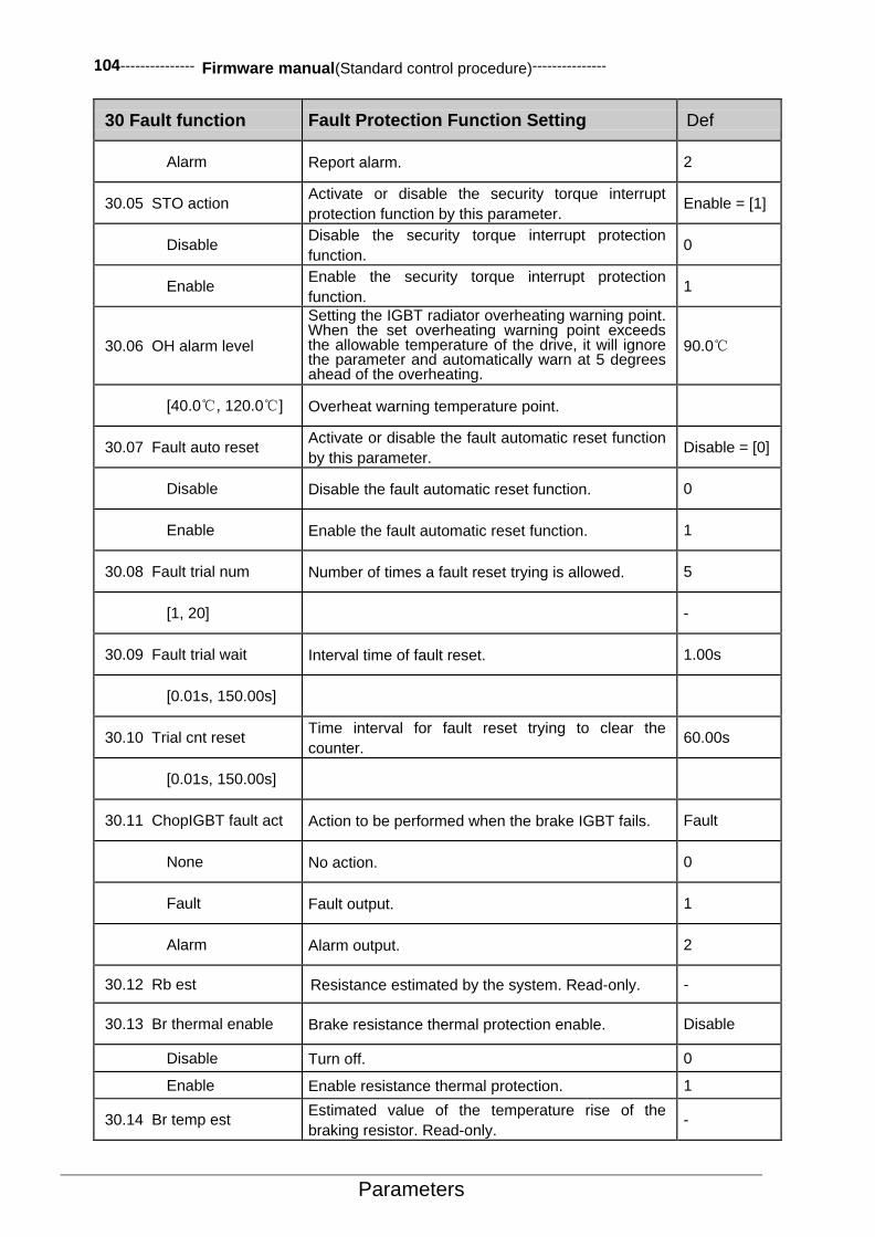
104--------------- Firmware manual(Standard control procedure)---------------
Parameters
30 Fault function Fault Protection Function Setting Def
Alarm Report alarm. 2
30.05 STO action Activate or disable the security torque interrupt
protection function by this parameter. Enable = [1]
Disable Disable the security torque interrupt protection
function. 0
Enable Enable the security torque interrupt protection
function. 1
30.06 OH alarm level
Setting the IGBT radiator overheating warning point. When the set overheating warning point exceeds the allowable temperature of the drive, it will ignore the parameter and automatically warn at 5 degrees ahead of the overheating.
90.0℃
[40.0℃, 120.0℃] Overheat warning temperature point.
30.07 Fault auto reset Activate or disable the fault automatic reset function
by this parameter. Disable = [0]
Disable Disable the fault automatic reset function. 0
Enable Enable the fault automatic reset function. 1
30.08 Fault trial num Number of times a fault reset trying is allowed. 5
[1, 20] -
30.09 Fault trial wait Interval time of fault reset. 1.00s
[0.01s, 150.00s]
30.10 Trial cnt reset Time interval for fault reset trying to clear the
counter. 60.00s
[0.01s, 150.00s]
30.11 ChopIGBT fault act Action to be performed when the brake IGBT fails. Fault
None No action. 0
Fault Fault output. 1
Alarm Alarm output. 2
30.12 Rb est Resistance estimated by the system. Read-only. -
30.13 Br thermal enable Brake resistance thermal protection enable. Disable
Disable Turn off. 0
Enable Enable resistance thermal protection. 1
30.14 Br temp est Estimated value of the temperature rise of the
braking resistor. Read-only. -
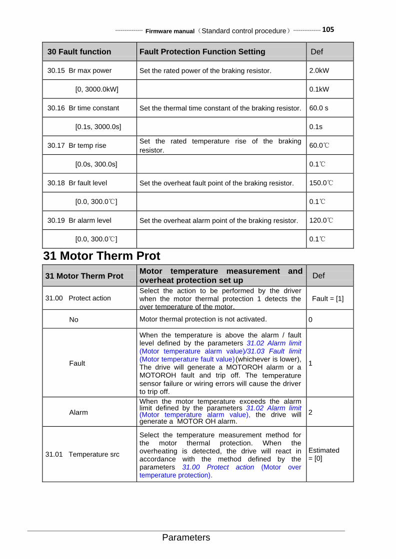
--------------- Firmware manual(Standard control procedure)--------------- 105
Parameters
30 Fault function Fault Protection Function Setting Def
30.15 Br max power Set the rated power of the braking resistor. 2.0kW
[0, 3000.0kW] 0.1kW
30.16 Br time constant Set the thermal time constant of the braking resistor. 60.0 s
[0.1s, 3000.0s] 0.1s
30.17 Br temp rise Set the rated temperature rise of the braking
resistor. 60.0℃
[0.0s, 300.0s] 0.1℃
30.18 Br fault level Set the overheat fault point of the braking resistor. 150.0℃
[0.0, 300.0℃] 0.1℃
30.19 Br alarm level Set the overheat alarm point of the braking resistor. 120.0℃
[0.0, 300.0℃] 0.1℃
31 Motor Therm Prot
31 Motor Therm Prot Motor temperature measurement and overheat protection set up
Def
31.00 Protect action Select the action to be performed by the driver when the motor thermal protection 1 detects the over temperature of the motor.
Fault = [1]
No Motor thermal protection is not activated. 0
Fault
When the temperature is above the alarm / fault level defined by the parameters 31.02 Alarm limit (Motor temperature alarm value)/31.03 Fault limit (Motor temperature fault value) (whichever is lower), The drive will generate a MOTOROH alarm or a MOTOROH fault and trip off. The temperature sensor failure or wiring errors will cause the driver to trip off.
1
Alarm
When the motor temperature exceeds the alarm limit defined by the parameters 31.02 Alarm limit (Motor temperature alarm value), the drive will generate a MOTOR OH alarm.
2
31.01 Temperature src
Select the temperature measurement method for the motor thermal protection. When the overheating is detected, the drive will react in accordance with the method defined by the parameters 31.00 Protect action (Motor over temperature protection).
Estimated = [0]

106--------------- Firmware manual(Standard control procedure)---------------
Parameters
31 Motor Therm Prot Motor temperature measurement and overheat protection set up
Def
Estimated
The monitoring temperature based on the motor thermal protection model which uses the thermal time constant of the motor (parameter 31.14Mot therm time (thermal protection time constant) ) and the motor load curve (parameter 31.10...31.12). . Only when the operating ambient temperature is different from the rated operating temperature of the motor, user need to adjust the relevant parameters. If the motor runs above the motor load curve, the motor temperature will increase. If the motor runs under the motor load curve (if the motor is overheated), the motor temperature will be reduced. Warning! If the the motor is not properly cooled due to the dust, the model can not perform the protection function to the motor.
0
KTY84 The motor temperature is monitored by the KTY84 temperature sensor.
1
PTC The motor temperature is monitored by the PTC sensor.
2
PT100_X1 Monitoring by a PT100 sensor. 3
PT100_X2 Monitoring by two PT100 sensors. 4
PT100_X3 Monitoring by three PT100 sensors. 5
31.02 Alarm limit Set the motor temperature warning point. 120.0℃
[0.0℃, 200.0℃] Motor temperature warning point.
31.03 Fault limit Set motor temperature fault point. 130.0℃
[0.0℃, 200.0℃] Motor temperature fault point.
31.04 Ambient temp Set the actual operating ambient temperature of the motor.
40.0℃
[0.0℃, 90.0℃] Ambient temperature of the motor.
31.05 Motor nom load
When the parameters 31.01Temperature src (Signal source of motor temperature) is set as Estimated (Estimated value), the heating model of the motor will use the load curve.
110.0%
[50.0%, 200.0%] Maximum load of the motor load curve.
31.06 Zero speed load
Define the maximum motor load when the load curve is zero. If the motor is equipped with an external fan to enhance the ventilation cooling of the motor, a greater load may be used. Refer to the motor manufacturer's recommendations.
70.0%
[50.0%, 100.0%] Zero load of the motor load curve.
31.07 Motor nom speed
Define the inflection frequency of the load curve, i.e. the load on the load curve defined by the value of the parameter 31.05 Nominal load (Rated speed load) begins to drop to the value defined by the parameter 31.06 Zero speed load (Zero speed load).
1500rpm
[150rpm, 30000rpm] The speed inflection point of the motor load curve.

--------------- Firmware manual(Standard control procedure)--------------- 107
Parameters
31 Motor Therm Prot Motor temperature measurement and overheat protection set up
Def
31.08 Motor nom temp rise
When the load of the motor reaches the rated current, define the temperature rise of the motor. Refer to the motor manufacturer's recommendations. When the parameters 31.01Temperature src (Signal source of motor temperature) is set as Estimated (Estimated value), the heating model of the motor will use the load curve.
60.0℃
[10.0℃, 200.0℃] Temperature rise of the motor rated load.
31.09 Therm time const
Defining the thermal time constant of the motor thermal protection model (i.e. the time that the temperature rise to the 60% of the rated temperature rise 63%). Refer to the motor manufacturer's recommendations.
1800.0s
[10.0s, 1800.0s] Motor thermal time constant.
31.10 External cool fan
For the variable frequency asynchronous motor or the synchronous motor, the cooling fan is independent, then the load capacity of zero speed is the same as that of the rated speed. For the non variable frequency motor, the motor comes with the fan and coaxial with the rotor, then need to be set to Auto cool. The correct setting is the premise of accurate temperature estimation.
Externalcool = [0]
Auto cool Non variable frequency motor. The load capacity of zero speed is lower than that of the rated speed.
0
External fan External independent fan. The load capacity of zero speed is the same as that of the rated speed.
1
31.11 Sensor input sel The signal input channel of the temperature sensor. Be sure to change the corresponding jump line of the terminal board to voltage type input.
AI1 = [0]
AI1 The temperature sensor is connected to the analog input AI1.
0
AI2 The temperature sensor is connected to the analog input AI2.
1
AI3 The temperature sensor is connected to the analog input AI3.
2
31.12 Sensor bias out
The selection of bias current source for the temperature sensor. Be sure to change the corresponding jump line of the terminal board to current type output.
AO1 = [0]
AO1 The temperature sensor is connected to the analog output AO1.
0
AO2 The temperature sensor is connected to the analog output AO2.
1
32 Factory Setting
32 Factory Setting
Optimization of the factory configuration of the kernel factory configuration settings (Default value )
Def
32.04 Kp_vdc_max Proportional gain of the overvoltage stall
controller,Q12. 4096

108--------------- Firmware manual(Standard control procedure)---------------
Parameters
32 Factory Setting
Optimization of the factory configuration of the kernel factory configuration settings (Default value )
Def
[2048, 16384] 1
32.05 Ki_vdc_max Integral gain of the overvoltage stall controller, Q16. 1638
[419, 16384] 1
32.06 Kp_vdc_max_f Proportional gain of the overvoltage stall frequency
controller, Q12. 4096
[2048, 16384] 1
32.07 Ki_vdc_max_f Integral gain of the overvoltage stall frequency
controller, Q16. 1638
[419, 16384] 1
32.08 Kp_fctrl Proportional gain of the open loop frequency
controller, Q12. 2048
[819, 16384] 1
32.09 Kp_vctrl Proportional gain of the open loop voltage
controller, Q12. 2048
[819, 16384] 1
32.10 AI1 gain Analog input AI1 correction gain, Q12 4096
[2048, 8192] 1
32.11 AI1 offset Analog input AI1 corrected offset, 1mV or 1mA 0
[-200, 200] 1mV/1mA
32.12 AI2 gain Analog input AI2 correction gain, Q12 4096
[2048, 8192] 1
32.13 AI2 offset Analog input AI2 corrected offset, 1mV or 1mA 0
[-200, 200] 1mV/1mA
32.14 AI3 gain Analog input AI3 correction gain, Q12 4096
[2048, 8192] 1
32.15 AI3 offset Analog input AI3 corrected offset, 1mV or 1mA 0
[-200, 200] 1mV/1mA
32.16 AO1 gain Analog output AO1 correction gain, Q12 3805
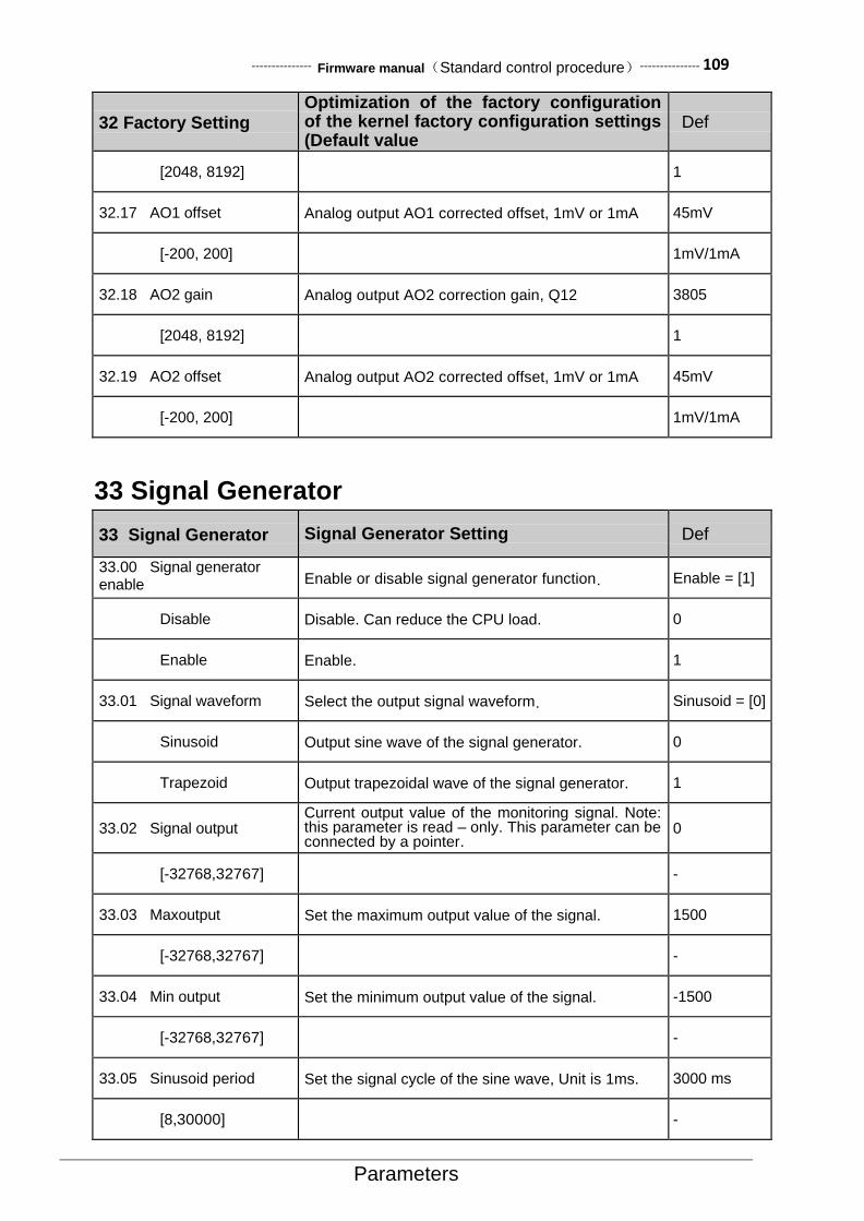
--------------- Firmware manual(Standard control procedure)--------------- 109
Parameters
32 Factory Setting Optimization of the factory configuration of the kernel factory configuration settings (Default value )
Def
[2048, 8192] 1
32.17 AO1 offset Analog output AO1 corrected offset, 1mV or 1mA 45mV
[-200, 200] 1mV/1mA
32.18 AO2 gain Analog output AO2 correction gain, Q12 3805
[2048, 8192] 1
32.19 AO2 offset Analog output AO2 corrected offset, 1mV or 1mA 45mV
[-200, 200] 1mV/1mA
33 Signal Generator
33 Signal Generator Signal Generator Setting Def
33.00 Signal generator enable
Enable or disable signal generator function. Enable = [1]
Disable Disable. Can reduce the CPU load. 0
Enable Enable. 1
33.01 Signal waveform Select the output signal waveform. Sinusoid = [0]
Sinusoid Output sine wave of the signal generator. 0
Trapezoid Output trapezoidal wave of the signal generator. 1
33.02 Signal output Current output value of the monitoring signal. Note: this parameter is read – only. This parameter can be connected by a pointer.
0
[-32768,32767] -
33.03 Maxoutput Set the maximum output value of the signal. 1500
[-32768,32767] -
33.04 Min output Set the minimum output value of the signal. -1500
[-32768,32767] -
33.05 Sinusoid period Set the signal cycle of the sine wave, Unit is 1ms. 3000 ms
[8,30000] -

110--------------- Firmware manual(Standard control procedure)---------------
Parameters
33 Signal Generator Signal Generator Setting Def
33.06 Traperise time Set the rise time of the trapezoidal wave from low
level to high level, Unit is 1ms. 6000 ms
[1,60000] -
33.07 Trape fall time Set the fall time of the trapezoidal wave from high
level to low level, Unit is 1ms. 6000ms
[1,60000] -
33.08 Trape high time Set the duration of the trapezoidal wave high level,
Unit is 0.01s. 1.00 s
[0.01,600.00] -
33.09 Trape low time Set the duration of the trapezoidal wave low level,
Unit is 0.01s. 1.00 s
[0.01,600.00] -
34 Logic Function
34 Logic Function Edge counters, comparators, combinational logic, timers and other functions setting
Def
34.00 Logic status
Can be connected to any bit of the status word by a bit pointer.
No Name Describption
0 Edge1 Edge counter 1 output.
1 Edge2 Edge counter 2 output.
2 Edge3 Edge counter 3 output.
3 Comp1 Comparator 1 output.
4 Comp2 Comparator 2 output.
5 Comp3 Comparator 3 output.
6 Logic1 Logic 1 function output.
7 Logic2 Logic 2 function output.
8 Logic3 Logic 3 function output.
9 Ontime1 Timer 1 output.
10 Ontime2 Timer 2 output.
11 Ontime3 Timer 3 output.
12~15
Reserved Retain
34.01 Edge cnt1 val Monitor the count value of the edge counter. Note
that this parameter is read – only. 0
[0, 65535] -
34.02 Edge cnt1 src Select the count signal source for the edge counter 1. when the specified edge of the signal is detected, the counter plus 1.
CONST.FALSE= [0]
P.01.00.00
User-defined pointer (01.00.00 from left to right take two digits as a set, indicates the parameter set, index, item number in turn. The actual value is determined by the current value of the parameter.)
-
CONST.FALSE Always be 0 0
CONST.TRUE Always be 1 1
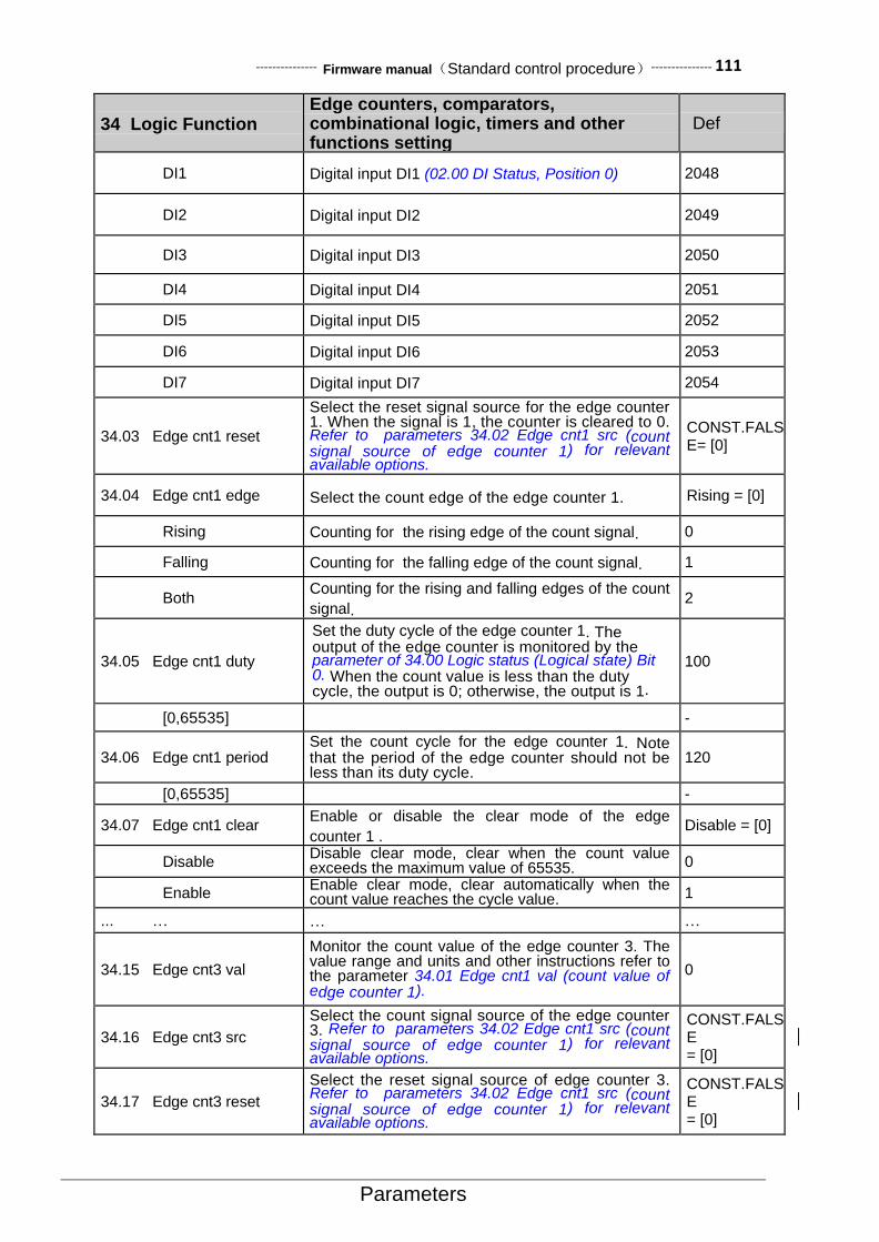
--------------- Firmware manual(Standard control procedure)--------------- 111
Parameters
34 Logic Function Edge counters, comparators, combinational logic, timers and other functions setting
Def
DI1 Digital input DI1 (02.00 DI Status, Position 0) 2048
DI2 Digital input DI2 2049
DI3 Digital input DI3 2050
DI4 Digital input DI4 2051
DI5 Digital input DI5 2052
DI6 Digital input DI6 2053
DI7 Digital input DI7 2054
34.03 Edge cnt1 reset
Select the reset signal source for the edge counter 1. When the signal is 1, the counter is cleared to 0. Refer to parameters 34.02 Edge cnt1 src (count signal source of edge counter 1) for relevant available options.
CONST.FALSE= [0]
34.04 Edge cnt1 edge Select the count edge of the edge counter 1. Rising = [0]
Rising Counting for the rising edge of the count signal. 0
Falling Counting for the falling edge of the count signal. 1
Both Counting for the rising and falling edges of the count
signal. 2
34.05 Edge cnt1 duty
Set the duty cycle of the edge counter 1. The output of the edge counter is monitored by the parameter of 34.00 Logic status (Logical state) Bit 0. When the count value is less than the duty cycle, the output is 0; otherwise, the output is 1.
100
[0,65535] -
34.06 Edge cnt1 period Set the count cycle for the edge counter 1. Note that the period of the edge counter should not be less than its duty cycle.
120
[0,65535] -
34.07 Edge cnt1 clear Enable or disable the clear mode of the edge
counter 1 . Disable = [0]
Disable Disable clear mode, clear when the count value exceeds the maximum value of 65535. 0
Enable Enable clear mode, clear automatically when the count value reaches the cycle value. 1
... … … …
34.15 Edge cnt3 val
Monitor the count value of the edge counter 3. The value range and units and other instructions refer to the parameter 34.01 Edge cnt1 val (count value of edge counter 1).
0
34.16 Edge cnt3 src
Select the count signal source of the edge counter 3. Refer to parameters 34.02 Edge cnt1 src (count signal source of edge counter 1) for relevant available options.
CONST.FALSE = [0]
34.17 Edge cnt3 reset
Select the reset signal source of edge counter 3. Refer to parameters 34.02 Edge cnt1 src (count signal source of edge counter 1) for relevant available options.
CONST.FALSE = [0]
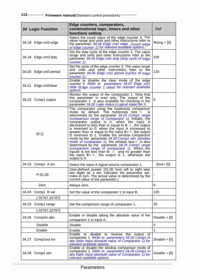
112--------------- Firmware manual(Standard control procedure)---------------
Parameters
34 Logic Function Edge counters, comparators, combinational logic, timers and other functions setting
Def
34.18 Edge cnt3 edge
Select the count value of the edge counter 3. The value range and units and other instructions refer to the parameter 34.04 Edge cnt1 edge (count edge of edge counter 1) for relevant available options.
Rising = [0]
34.19 Edge cnt3 duty
Set the duty cycle of the edge counter 3. The value range and units and other instructions refer to the parameter 34.05 Edge cnt1 duty (duty cycle of edge counter 1).
100
34.20 Edge cnt3 period
Set the cycle of the edge counter 3. The value range and units and other instructions refer to the parameter 34.06 Edge cnt1 period (cycles of edge counter 1).
120
34.21 Edge cnt3clear
Enable or disable the clear mode of the edge counter 3. Refer to parameters 34.07 Edge cnt1 clear (Edge counter 1 clear) for relevant available options.
34.22 Comp1 output
Monitor the output of the comparator 1. Note that this parameter is read only. The output of the comparator 1 is also available for checking in the parameter 34.00 Logic status (Logical state) Bit 3.
0
[0,1]
The comparator using the hysteresis comparison mode by default. The hysteresis size Δ is determined by the parameter 34.25 Comp1 range (comparison range of Comparator 1). Initially, the comparator output is 0, when the input A decreased to less than or equal to B-Δ, the output is reversed to 0; when the input A increased to greater than or equal to the input B+Δ,the output is reversed to 1. Enable the window comparison mode by the parameter 34.28 Comp1 win (window mode of comparator 1), the window sizeΔ is also determined by the parameter 34.25 Comp1 range (comparison range of comparator 1). When the inputA is not less than B- Δ and no greater than the input B+Δ , the output is 1, otherwise the output is 0.
-
34.23 Comp1 A src Select the input A signal source comparator 1. Zero= [0]
P.01.00
User-defined pointer (01.00 from left to right take two digits as a set, indicates the parameter set, index in turn. The actual value is determined by the current value of the parameter.)
-
Zero Always zero. 0
34.24 Comp1 B val Set the value of the comparator 1 to input B. 120
[-32767,32767] -
34.25 Comp1 range Set the comparison range of comparator 1. 20
[-32767,32767]
34.26 Comp1in abs Enable or disable taking the absolute value of the
comparator 1 to input A. Disable = [0]
Disable Disable 0
Enable Enable 1
34.27 Comp1out inv
Enable or disable to reverse the output of comparator 1. Refer to parameters 34.26 Comp1 in abs (take input absolute value of Comparator 1) for relevant available options.
Disable = [0]
34.28 Comp1 win
Enable or disable the window comparison mode of comparator 1. Refer to parameters 34.26 Comp1 in abs (take input absolute value of Comparator 1) for relevant available options.
Disable = [0]

--------------- Firmware manual(Standard control procedure)--------------- 113
Parameters
34 Logic Function Edge counters, comparators, combinational logic, timers and other functions setting
Def
…
34.36 Comp3 output
Monitor the output of comparator 3. The value range and units and other instructions refer to the parameter 34.22 Comp1 output (comparator 1 output).
0
34.37 Comp3 A src
Select the signal source of comparator 3 to input A. Refer to parameters 34.23 Comp1 A src (signal source of comparator 1 input A) for relevant available options.
Zero= [0]
34.38 Comp3 B val
Set the value of comparator 3 to input B. The value range and units and other instructions refer to the parameter 34.24 Comp1B val (the value of the comparator 1 input B).
100
34.39 Comp3 range
Set the comparison range of comparator 3. The value range and units and other instructions refer to the parameter 34.25 Comp1 range (comparison range of comparator 1).
20
34.40 Comp3 in abs
Enable or disable the absolute value of comparator 3 input A. Refer to parameters 34.26 Comp1 in abs (comparison range of comparator 1) for relevant available options.
Disable = [0]
34.41 Comp3 out inv
Enable or disable the output of comparator 3. Refer to parameters 34.26 Comp1 in abs (input absolute value of comparator 1) for relevant available options.
Disable = [0]
34.42 Comp3 win
Enable or disable the window comparison mode of comparator 3. Refer to parameters 34.26 Comp1 in abs (input absolute value of comparator 1) for relevant available options.
Disable = [0]
34.43 Logic1 A src Select the signal source of logic 1 input A. CONST.FALSE= [0]
P.01.00.00
User-defined pointer (01.00.00 from left to right take two digits as a set, indicates the parameter set, index, item number in turn. The actual value is determined by the current value of the parameter.)
-
CONST.FALSE Always be 0 0
CONST.TRUE Always be 1 1
DI1 Digital input DI1 (02.00 DI State,Position 0) 2048
DI2 Digital input DI2 2049
DI3 Digital input DI3 2050
DI4 Digital input DI4 2051
DI5 Digital input DI5 2052
DI6 Digital input DI6 2053
DI7 Digital input DI7 2054
34.44 Logic1 B src Select the signal source of logic 1 input B. Refer to parameters 34.43 Logic1 A src (signal source of Logic 1 input A) for relevant available options.
CONST.FALSE= [0]
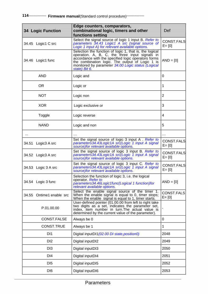
114--------------- Firmware manual(Standard control procedure)---------------
Parameters
34 Logic Function Edge counters, comparators, combinational logic, timers and other functions setting
Def
34.45 Logic1 C src Select the signal source of logic 1 input B. Refer to parameters 34.43 Logic1 A src (signal source of Logic 1 input A) for relevant available options.
CONST.FALSE= [0]
34.46 Logic1 func
Selection the function of logic 1, that is, the logical operation. A, B, C, the three input signals in accordance with the specified logic operators forms the combination logic. The output of Logic 1 is monitored by parameter 34.00 Logic status (Logical state) Bit 6.
AND = [0]
AND Logic and 0
OR Logic or 1
NOT Logic non 2
XOR Logic exclusive or 3
Toggle Logic reverse 4
NAND Logic and non 5
... … …
34.51 Logic3 A src Set the signal source of logic 3 input A . Refer to parameters34.43Logic1A src(Logic 1 input A signal source)for relevant available options.
CONST.FALSE= [0]
34.52 Logic3 A src Set the signal source of logic 3 input B. Refer to parameters34.43Logic1A src(Logic 1 input A signal source)for relevant available options.
CONST.FALSE= [0]
34.53 Logic 3 A src Set the signal source of logic 3 input C. Refer to parameters34.43Logic1A src(Logic 1 input A signal source)for relevant available options.
CONST.FALSE= [0]
34.54 Logic 3 func
Selection the function of logic 3, i.e. the logical operator. Refer to parameters34.46Logic1func(Logical 1 function)for relevant available options.
AND = [0]
34.55 Ontime1 enable src Select the enable signal source of the timer 1. When the enable signal is equal to 0, timer stops; When the enable signal is equal to 1, timer starts.
CONST.FALSE= [0]
P.01.00.00
User-defined pointer (01.00.00 from left to right take two digits as a set, indicates the parameter set, index, item number in turn.The actual value is determined by the current value of the parameter).
-
CONST.FALSE Always be 0 0
CONST.TRUE Always be 1 1
DI1 Digital inputDI1(02.00 DI state,position0) 2048
DI2 Digital inputDI2 2049
DI3 Digital inputDI3 2050
DI4 Digital inputDI4 2051
DI5 Digital inputDI5 2052
DI6 Digital inputDI6 2053

--------------- Firmware manual(Standard control procedure)--------------- 115
Parameters
34 Logic Function Edge counters, comparators, combinational logic, timers and other functions setting
Def
DI7 Digital inputDI7 2054
34.56 Ontime1 comp val
Set the comparison value of timer 1,Units as 0.1s.Timer 1 output by parameter34.00Logic status(Logical state)Bit 9 monitoring,When the count value is less than the comparison value,The output is 0,otherwise,The output is 1.
6553.5 s
[0.0, 6553.5]
34.57 Ontime 1 cnt Monitor timer 1 count value.Notice, this parameter
is read – only. 0
[0, 65535] -
... … … …
34.61 Ontime3 enable src
Select the enable signal source of timer 3. Refer to parameters 34.55 Ontime1 enable src (The timer 1 lose enabling signal source) for relevant available options.
CONST.FALSE= [0]
34.62 Ontime3 comp val
Set the comparison value of timer 3. The value range and units and other instructions refer to the parameter 34.56 Ontime1comp val(Comparison value of timer 1).
6553.5 s
34.63 Ontime 3 cnt Monitor the count value of timer 3. The value range and units and other instructions refer to the parameter 34.57 Ontime1cnt(Timer 1 count value).
0
35 Math function
35 Math function Linear scaling、Arithmetic expression、integrator、Filter and other functions set up
Def
35.00 Linear 1 x src Select the signal source of retiomatric conversion
1 input X. Zero = [0]
P.01.00
User-defined pointer (01.00 from left to right take two digits a set, indicates the parameter set, index in turn. The actual value is determined by the current value of the parameter).
-
Zero Always zero 0
35.01 Linear1 y Set the value of the retiomatric conversion 1 output y. Note this parameter is read only. User can connect to the parameters by a pointer.
0
[-32767,32767] -
35.02 Linear1 x max Set and select the maximum value of the
ratiometric conversion input X. 32767
[-32767,32767] -
35.03 Linear1 x min Set and select the minimum value of the ratiometric
conversion input X. 0
[-32767,32767] -

116--------------- Firmware manual(Standard control procedure)---------------
Parameters
35 Math function Linear scaling、Arithmetic expression、integrator、Filter and other functions set up
Def
35.04 Linear1 y max Set and select the maximum value of the
ratiometric conversion output Y. 32767
[-32767,32767] -
35.05 Linear1 y min Set and select the minimum value of the ratiometric
conversion output Y. 0
[-32767,32767] -
35.06 Linear 1 x abs Enable or disable the absolute value of the
ratiometric conversion 1 input X. Disable = [0]
Disable Disable 0
Enable Enable 1
35.07 Linear1 y dec Set the decimal digits of the ratiometric conversion
output Y. 0
[0, 7] -
35.08 Linear1 y unit Select the unit of the ratiometric conversion 1
output Y. 0
[0, 63] -
... … … …
35.18 Linear 3 x src
Select the signal source of the ratiometric conversion 3 input X. Refer to parameters35.00Linear1 x src(Proportional conversion 1 input X signal source)for relevant available options.
Zero = [0]
35.19 Linear 3 y
Value of the ratiometric conversion 3 output Y. The value range and units and other instructions refer to the parameter 35.01 Linear1 output(Ratio conversion 1 output y value).
0
35.20 Linear 3 x max
Set the maximum value the ratiometric conversion 3 input X. The value range and units and other instructions refer to the parameter 35.02 Linear1 x max(Proportional conversion 1 input x maximum).
32767
35.21 Linear3 x min
Set the minimum value the ratiometric conversion 3 input X. The value range and units and other instructions refer to the parameter 35.03 Linear1 x min(Proportional conversion 1 input x minimum value).
0
35.22 Linear3 y max
Set the maximum value the ratiometric conversion 3 input Y. The value range and units and other instructions refer to the parameter 35.04 Linear1 y max(Proportional conversion 1 output y maximum value).
32767
35.23 Linear3 y min
Set the minimum value the ratiometric conversion 3 input Y. The value range and units and other instructions refer to the parameter 35.06Linear1 y min(Proportional conversion 1 input yminimum value).
0
35.24 Linear3 x abs Enable or disable the absolute value of the
ratiometric conversion 3 input X. Disable = [0]
35.25 Linear3 y dec Set the decimal digits of the ratiometric conversion
3 output Y. 0
35.26 Linear3 y unit Select the unit of the ratiometric conversion 3
output Y. 0

--------------- Firmware manual(Standard control procedure)--------------- 117
Parameters
35 Math function Linear scaling、Arithmetic expression、integrator、Filter and other functions set up
Def
35.27 Math1 x src Select the signal source of arithmetic 1 input X. Zero = [0]
P.01.00
User-defined pointer (01.00 from left to right take two digits as a set, indicates the parameter set,, index in turn. The actual value is determined by the current value of the parameter).
-
Zero Always zero 0
35.28 Math1 y src
Select the signal source of arithmetic 1 input Y.Refer to parameters 35.27Math1 x src(Arithmetic 1 input X signal source)for relevant available options.
Zero = [0]
35.29 Math1 func
Select the function of arithmetic 1, i.e. the arithmetic operator. Input X and Y in accordance with the specified arithmetic operator to form an arithmetic expression.
Add = [0]
Add x + y 0
Sub x - y 0
Min The small one of X and Y 0
Max The big one of X and Y 0
Abs Absolute value of X 0
Mul x * y / k(k is a scaling factor) 0
Div X * k / y(k is a scaling factor) 0
35.30 Math 1 factor When the parameter 35.29 Math1 func(Function of arithmetic1)select multiply or divide as an arithmetic operator, set the scaling factor k of arithmetic 1.
0
[-32768,32767] -
35.31 Math1 output Monitor the output of arithmetic 1. Note that this parameter is read – only. It can be connected to the parameter by a pointer.
0
[-32768,32767] -
... … … …
35.37 Math 3 x src Select the signal source of arithmetic 3 input X. Refer to parameters35.27Math1 x src(Arithmetic 1 input X signal source)for relevant available options.
Zero = [0]
35.38 Math3 y src
Select the signal source of arithmetic 3 input Y. Refer to the parameters35.27Math1 x src(Arithmetic 1 input X signal source)for relevant available options.
Zero = [0]
35.39 Math 3 func
Select the function of arithmetic 1, i.e. the arithmetic operator. Refer to parameters35.29Math1 func(Function of arithmetic 1)for relevant available options.
Add = [0]
35.40 Math 3 factor
When parameters 35.39 Math3func(Function of arithmetic 3)select multiply or divide as an arithmetic operator, set the scaling factor k of arithmetic 3.
0

118--------------- Firmware manual(Standard control procedure)---------------
Parameters
35 Math function Linear scaling、Arithmetic expression、integrator、Filter and other functions set up
Def
35.41 Math 3 output Monitor the output of arithmetic 3. Note that this parameter is read – only. It can be connected to the parameter by a pointer.
0
35.42 Integrator1src
Select the signal source of integrator1 input. Refer
to parameters35.27Math1 x src(Arithmetic 1 input X
signal source)for the relevant available options.
Zero = [0]
35.43 Integrator 1 output Monitor the output of integrator 1. Note that this parameter is read – only. It can be connected to the parameter by a pointer.
0
[0, 65535] -
35.44 Integrator1scaling 0
[0, 65535] -
…… … …
35.48 Integrator3src Select the signal source of integrator3 input. Refer to parameters35.42Integrator1 src(1 input signal source integrator)for relevant available options.
35.49 Integrator3output Monitor the output of integrator 3. It can be
connected to the parameter by a pointer.
35.50 Integrator3scaling
35.51 Filter1 input src Select the signal source of a low pass filter 1 input. Zero = [0]
P.01.00
User-defined pointer (01.00 from left to right take two digits as a set, indicates the parameter set, index in turn. The actual value is determined by the current value of the parameter).
-
Zero Always zero 0
35.52 Filter1 output Monitor the output of the low pass filter 1. Note that this parameter is read – only. It can be connected to the parameter by a pointer.
0
[0, 65535] -
35.53 Filter1 timeconst Set the filter time constant of low pass filter 1. Unit is
0.01s. 1.00 s
[0.00, 655.35] -
…… … …
35.57 Filter3 input src Select the signal source of a low pass filter 3 input. Refer to parameters35.51 Filter1 src(Filter 1 input signal source)for relevant available option.
Zero = [0]
35.58 Filter 3 output Monitor the output of the low pass filter 3. The value range and units and other instructions refer to the parameter 35.52Filter1 output(Filter 1 output).
0
35.59 Filter 3 time const
Set the filter time constant of the low pass filter 3. The value range and units and other instructions refer to the parameter 35.53Filter1 timeconst(Filter 1 time constant).
1.00 s

--------------- Firmware manual(Standard control procedure)--------------- 119
Parameters
40 Pos control 40Pos control
Position control, positioning control Def
40.00 Pos ctrl mode Position control mode Disable
POS CTRL Positioning control, including the trajectory planning.
Can support for fixed length and fixed angle control. 0
SERVO CTRL servo control supports for conventional servo
function. 1
ZERO SERVO Zero servo control. 2
40.01 Pos ctrl enable Position control enable signal source selection CONST.FALSEDisable
40.02 Pos mark type Position reference signal type. Zmark = [0]
Zmark Take Z pulse as reference signal 0
DI
Take the external terminal signal as reference signal
the signal source is specified by the parameters of
40.03.
1
40.03 Pos mark src Selection of external reference signal source. CONST.FALSE
40.04 Orient dir Direction of spindle orientation. 0
AUTO Automatic 0
FWD Positive 1
REV Reverse 2
40.05 Pos spd set Spindle positioning speed size 300rpm
[0, 30000]
40.06 Pos refsrc Selection of the location given signal source PULSE = [0]
PULSE The position given source is given by the pulse train 0
FIELDBUS The location given source is given by the Fieldbus 1
40.07 Pos ctrl gain Position loop gain 40Hz
[1, 100]
40.08 Pos ffwd filter filtering time of position feedforward 2.0ms
[0.0, 50.0]
40.09 Pos sel in1 Signal source 1 of multi segment position selection CONST.FALSE
40.10 Pos sel in2 Signal source 2 of multi segment position selection CONST.FALSE

120--------------- Firmware manual(Standard control procedure)---------------
Parameters
40Pos control
Position control, positioning control Def
40.11 Inc pos sel in1 Signal source 1 of incremental position selection CONST.FALSE
40.12 Inc pos sel in2 Signal source 2 of incremental position selection CONST.FALSE
40.13 Inc pos sel in3 Signal source 3 of incremental position selection CONST.FALSE
40.14 Feed fwd rqst Selection of forward feed request signal source CONST.FALSE
40.15 Feed rev rqst Selection of reverse feed request signal source CONST.FALSE
40.16 Pos rpt rqst Selection of repeat location request signal source CONST.FALSE
40.17 Pos err lim The allowable location error of the positioning 100
[10, 1000]
40.18 Pos preset1_rev The number of cycles of the set value for multi
segment position 1. 0
[-32768, 32767]
40.19 Pos preset1_pul The number of pulses of the set value for multi
segment position 1. 0
[-32768, 32767]
40.20 Pos preset2_rev The number of cycles of the set value for multi
segment position 2. 0
[-32768, 32767]
40.21 Pos preset 2_pul The number of pulses of the set value for multi
segment position 2. 0
[-32768, 32767]
40.22 Pos preset 3_rev The number of cycles of the set value for multi
segment position 3. 0
[-32768, 32767]
40.23 Pos preset 3_pul The number of pulses of the set value for multi
segment position 3. 0
[-32768, 32767]
40.24 Pos preset4_rev The number of cycles of the set value for multi
segment position 4. 0
[-32768, 32767]
40.25 Pos preset4_pul The number of pulses of the set value for multi
segment position 4. 0
[-32768, 32767]

--------------- Firmware manual(Standard control procedure)--------------- 121
Parameters
40Pos control
Position control, positioning control Def
40.26 Inc pos preset1_rev The number of cycles of the set value for
incremental position 1. 0
40.27 Inc pos preset1_pul The number of pulses of the set value for
incremental position 1. 0
40.28 Inc pos preset2_rev The number of cycles of the set value for
incremental position 2. 0
40.29 Inc pos preset2_pul The number of pulses of the set value for
incremental position 2. 0
40.30 Inc pos preset3_rev The number of cycles of the set value for
incremental position 3. 0
40.31 Inc pos preset3_pul The number of pulses of the set value for
incremental position 3. 0
40.32 Inc pos preset4_rev The number of cycles of the set value for
incremental position 4. 0
40.33 Inc pos preset4_pul The number of pulses of the set value for
incremental position 4. 0
40.34 Inc pos preset5_rev The number of cycles of the set value for
incremental position 5. 0
40.35 Inc pos preset5_pul The number of pulses of the set value for
incremental position 5. 0
40.36 Inc pos preset6_rev The number of cycles of the set value for
incremental position 6. 0
40.37 Inc pos preset6_pul The number of pulses of the set value for
incremental position 6. 0
40.38 Inc pos preset7_rev The number of cycles of the set value for
incremental position 7. 0
40.39 Inc pos preset7_pul The number of pulses of the set value for
incremental position 7. 0
40.40 Inc pos preset8_rev The number of cycles of the set value for
incremental position 8. 0
40.41 Inc pos preset8_pul The number of pulses of the set value for
incremental position 8. 0
40.42 Force home rqst signal source of force back to zero request. CONST.FALSE
42 Mech brake
42Mech brake Mechanical brake control of lifting equipment
Def
42.00 Mech brake enable The mechanical brake enable control Disable
Disable Not enabled. Brake output signal is always turn off. 0
Enable Enabled. No brake response. 1
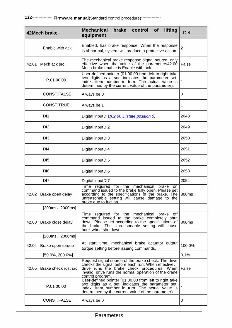
122--------------- Firmware manual(Standard control procedure)---------------
Parameters
42Mech brake Mechanical brake control of lifting equipment
Def
Enable with ack Enabled, has brake response. When the response
is abnormal, system will produce a protective action. 2
42.01 Mech ack src The mechanical brake response signal source, only effective when the value of the parameters42.00 Mech brake enable is Enable with ack.
False
P.01.00.00
User-defined pointer (01.00.00 from left to right take two digits as a set, indicates the parameter set, index, item number in turn. The actual value is determined by the current value of the parameter).
-
CONST.FALSE Always be 0 0
CONST.TRUE Always be 1 1
DI1 Digital inputDI1(02.00 DIstate,position 0) 2048
DI2 Digital inputDI2 2049
DI3 Digital inputDI3 2050
DI4 Digital inputDI4 2051
DI5 Digital inputDI5 2052
DI6 Digital inputDI6 2053
DI7 Digital inputDI7 2054
42.02 Brake open delay
Time required for the mechanical brake on command issued to the brake fully open. Please set according to the specifications of the brake. The unreasonable setting will cause damage to the brake due to friction.
800ms
[200ms,2000ms]
42.03 Brake close delay
Time required for the mechanical brake off command issued to the brake completely shut down. Please set according to the specifications of the brake. The Unreasonable setting will cause hook when shutdown.
800ms
[200ms,2000ms]
42.04 Brake open torque At start time, mechanical brake actuator output
torque setting before issuing commands. 100.0%
[50.0%, 200.0%] 0.1%
42.05 Brake check rqst src
Request signal source of the brake check. The drive checks the signal before each run. When effective,drive runs the brake check procedures. When invalid, drive runs the normal operation of the crane control program.
False
P.01.00.00
User-defined pointer (01.00.00 from left to right take two digits as a set, indicates the parameter set, index, item number in turn. The actual value is determined by the current value of the parameter).
-
CONST.FALSE Always be 0 0
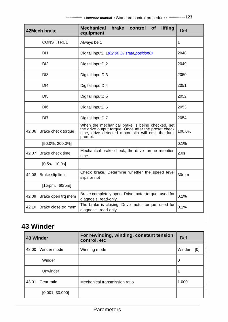
--------------- Firmware manual(Standard control procedure)--------------- 123
Parameters
42Mech brake Mechanical brake control of lifting equipment
Def
CONST.TRUE Always be 1 1
DI1 Digital inputDI1(02.00 DI state,position0) 2048
DI2 Digital inputDI2 2049
DI3 Digital inputDI3 2050
DI4 Digital inputDI4 2051
DI5 Digital inputDI5 2052
DI6 Digital inputDI6 2053
DI7 Digital inputDI7 2054
42.06 Brake check torque
When the mechanical brake is being checked, set the drive output torque. Once after the preset check time, drive detected motor slip will emit the fault prompt.
100.0%
[50.0%, 200.0%] 0.1%
42.07 Brake check time Mechanical brake check, the drive torque retention
time. 2.0s
[0.5s,10.0s]
42.08 Brake slip limit Check brake. Determine whether the speed level
slips or not 30rpm
[15rpm,60rpm]
42.09 Brake open trq mem Brake completely open. Drive motor torque, used for
diagnosis, read-only. 0.1%
42.10 Brake close trq mem The brake is closing. Drive motor torque, used for
diagnosis, read-only. 0.1%
43 Winder
43 Winder For rewinding, winding, constant tension control, etc
Def
43.00 Winder mode Winding mode Winder = [0]
Winder 0
Unwinder 1
43.01 Gear ratio Mechanical transmission ratio 1.000
[0.001, 30.000]

124--------------- Firmware manual(Standard control procedure)---------------
Parameters
43 Winder For rewinding, winding, constant tension control, etc
Def
43.02 Thickness Material thickness 0.100mm
[0.001, 30.000]
43.03 Web width Strip material width 1000mm
[1, 30000]
43.04 Density Material density 1000kg/m3
[1, 30000]
43.05 Line spd max Maximum linear speed 300.0m/min
[0.1, 3000.0]
43.06 Line spd src Selection of line speed input signal source AI1 scaled
43.07 Dia calc mode Roller diameter calculation method LINESPEED
LINE SPEED 0
ENCODER 1
ROLL_PULSE 2
EXT_FBK Calculated by parameter 43.08 3
43.08 Roll dia src Selection of signal source for external calculation of
the roller diameter AI1 scaled
43.09 Roll pulse src Selection of drum pulse signal source CONST.FALSE
43.10 Roll pulse scaling Drum pulse rate, i.e. the number of pulses
generated by the drum 1
43.11 Core diameter Empty disc diameter 100mm
43.12 Full roll dia Full size disc diameter 1
43.13 Dia reset rqst Selection of the Diameter reset request signal
source
CONST.FALSE
43.14 Dia preset rqst Selection of volume diameter preset request signal
source
CONST.FALSE
43.15 Dia preset data Diameter preset value 100mm
43.16 Min spd dia calc Maximum speed allowed for calculation of roll
diameter 30rpm
43.17 Tense src Selection of the tension given source AI2 scaled

--------------- Firmware manual(Standard control procedure)--------------- 125
Parameters
43 Winder For rewinding, winding, constant tension control, etc
Def
43.18 Tmax Maximum tension value setting 30.0N
43.19 Tape mode Tension taper mode selection 0
43.20 Max tape Maximum gain of tension taper control 0.0%
[0, 100.0]
47 Multi step ctrl
47Multi step ctrl
Simple multi stage speed circle control to save PLC and other control equipments. Support 16 stage speed and time definitions.
Def
47.00 Speed out Module speed output, read-only.The speed of a given pointer is controlled by pointing to the parameter P47.00.
-
47.01 Run enable src Multi stage speed operation enables the signal source,the Bit pointer.The default is controlled by a motor operating signal.
P.06.00.04
47.02 Mode Select the multi stage speed control mode. 0
Single Single cycle,And keep the final value. 0
Repeat Circulation mode. 1
Single & Stop Single cycle,And automatically shut down。Restart
need to issue a stop command. 2
47.03 Save mode Shutdown or power down whether in memory status 0
Disable Not enabled. Shut down with no nomemory. 0
Enable Storage. Stop memory operation phase. 1
47.04 Stage At the current stage of the multi segment speed
loop, user can edit as the starting phase. 0
[0, 15]
47.05 Timer The current cycle phase corresponds to the clock,
users can edit as initial time. 0
[0.0, 6553.5] 0.1min
47.06 TimeSet 0 The zeroth section corresponds to the time setting.To set to 0 to indicate that the segment is ignored and skipped automatically.
0
[0.0, 6553.5] 0.1min

126--------------- Firmware manual(Standard control procedure)---------------
Parameters
47Multi step ctrl
Simple multi stage speed circle control to save PLC and other control equipments. Support 16 stage speed and time definitions.
Def
47.07 TimeSet 1 The first section corresponds to the time setting. Set to 0 to indicate that the segment is ignored and skipped automatically.
0
[0.0, 6553.5] 0.1min
47.08 TimeSet 2 The second section corresponds to the time setting. Set to 0 to indicate that the segment is ignored and skipped automatically.
0
[0.0, 6553.5] 0.1min
47.09 TimeSet 3 The third section corresponds to the time setting. Set to 0 to indicate that the segment is ignored and skipped automatically.
0
[0.0, 6553.5] 0.1min
47.10 TimeSet 4 The fourth section corresponds to the time setting. Set to 0 to indicate that the segment is ignored and skipped automatically.
0
[0.0, 6553.5] 0.1min
47.11 TimeSet5 The fifth section corresponds to the time setting. Set to 0 to indicate that the segment is ignored and skipped automatically.
0
[0.0, 6553.5] 0.1min
47.12 TimeSet 6 The sixth section corresponds to the time setting. Set to 0 to indicate that the segment is ignored and skipped automatically.
0
[0.0, 6553.5] 0.1min
47.13 TimeSet 7 The seventh section corresponds to the time setting. Set to 0 to indicate that the segment is ignored and skipped automatically.
0
[0.0, 6553.5] 0.1min
47.14 TimeSet 8 The eighth section corresponds to the time setting. Set to 0 to indicate that the segment is ignored and skipped automatically.
0
[0.0, 6553.5] 0.1min
47.15 TimeSet 9 The nineth section corresponds to the time setting. Set to 0 to indicate that the segment is ignored and skipped automatically.
0
[0.0, 6553.5] 0.1min
47.16 TimeSet 10 The tenth section corresponds to the time setting. Set to 0 to indicate that the segment is ignored and skipped automatically.
0
[0.0, 6553.5] 0.1min
47.17 TimeSet 11 The eleventh section corresponds to the time setting. Set to 0 to indicate that the segment is ignored and skipped automatically.
0
[0.0, 6553.5] 0.1min

--------------- Firmware manual(Standard control procedure)--------------- 127
Parameters
47Multi step ctrl
Simple multi stage speed circle control to save PLC and other control equipments. Support 16 stage speed and time definitions.
Def
47.18 TimeSet 12 The twelfth section corresponds to the time setting. Set to 0 to indicate that the segment is ignored and skipped automatically.
0
[0.0, 6553.5] 0.1min
47.19 TimeSet 13 The thirteenth section corresponds to the time setting. Set to 0 to indicate that the segment is ignored and skipped automatically.
0
[0.0, 6553.5] 0.1min
47.20 TimeSet 14 The fourteenth section corresponds to the time setting. Set to 0 to indicate that the segment is ignored and skipped automatically.
0
[0.0, 6553.5] 0.1min
47.21 TimeSet 15 The fifteenth section corresponds to the time setting. Set to 0 to indicate that the segment is ignored and skipped automatically.
0
[0.0, 6553.5] 0.1min
47.22 SpeedSet 0 Corresponding speed settings of the segement 0. 0
[0, 65535] 1rpm
47.23 SpeedSet 1 Corresponding speed settings of the segement 1. 0
[0, 65535] 1rpm
47.24 SpeedSet 2 Corresponding speed settings of the segement 2. 0
[0, 65535] 1rpm
47.25 SpeedSet 3 Corresponding speed settings of the segement 3. 0
[0, 65535] 1rpm
47.26 SpeedSet 4 Corresponding speed settings of the segement 4. 0
[0, 65535] 1rpm
47.27 SpeedSet 5 Corresponding speed settings of the segement 5. 0
[0, 65535] 1rpm
47.28 SpeedSet 6 Corresponding speed settings of the segement 6. 0
[0, 65535] 1rpm
47.29 SpeedSet 7 Corresponding speed settings of the segement 7. 0

128--------------- Firmware manual(Standard control procedure)---------------
Parameters
47Multi step ctrl
Simple multi stage speed circle control to save PLC and other control equipments. Support 16 stage speed and time definitions.
Def
[0, 65535] 1rpm
47.30 SpeedSet 8 Corresponding speed settings of the segement 8. 0
[0, 65535] 1rpm
47.31 SpeedSet 9 Corresponding speed settings of the segement 9. 0
[0, 65535] 1rpm
47.32 SpeedSet 10 Corresponding speed settings of the segement 10. 0
[0, 65535] 1rpm
47.33 SpeedSet 11 Corresponding speed settings of the segement 11. 0
[0, 65535] 1rpm
47.34 SpeedSet 12 Corresponding speed settings of the segement 12. 0
[0, 65535] 1rpm
47.35 SpeedSet 13 Corresponding speed settings of the segement 13. 0
[0, 65535] 1rpm
47.36 SpeedSet 14 Corresponding speed settings of the segement 14. 0
[0, 65535] 1rpm
47.37 SpeedSet 15 Corresponding speed settings of the segement 15. 0
[0, 65535] 1rpm
48Switch Sync
48 Switch sync
Used for synchronous or asynchronous AC motors soft start,power frequency synchronous,etc. To achieve the impact of the motor without access to the grid.
Def
48.00 status Status word for synchronous switching controller. 0
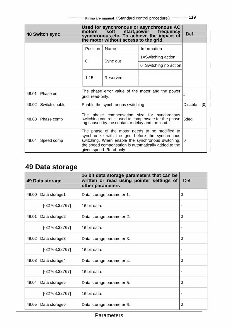
--------------- Firmware manual(Standard control procedure)--------------- 129
Parameters
48 Switch sync
Used for synchronous or asynchronous AC motors soft start,power frequency synchronous,etc. To achieve the impact of the motor without access to the grid.
Def
Position Name Information
0 Sync out 1=Switching action.
0=Switching no action.
1:15 Reserved
48.01 Phase err The phase error value of the motor and the power
grid, read-only. -
48.02 Switch enable Enable the synchronous switching Disable = [0]
48.03 Phase comp The phase compensation size for synchronous switching control is used to compensate for the phase lag caused by the contactor delay and the load.
6deg
48.04 Speed comp
The phase of the motor needs to be modified to synchronize with the grid before the synchronous switching. When enable the synchronous switching, the speed compensation is automatically added to the given speed. Read-only.
0
49 Data storage
49 Data storage 16 bit data storage parameters that can be written or read using pointer settings of other parameters
Def
49.00 Data storage1 Data storage parameter 1. 0
[-32768,32767] 16 bit data. -
49.01 Data storage2 Data storage parameter 2. 0
[-32768,32767] 16 bit data. -
49.02 Data storage3 Data storage parameter 3. 0
[-32768,32767] 16 bit data. -
49.03 Data storage4 Data storage parameter 4. 0
[-32768,32767] 16 bit data. -
49.04 Data storage5 Data storage parameter 5. 0
[-32768,32767] 16 bit data. -
49.05 Data storage6 Data storage parameter 6. 0
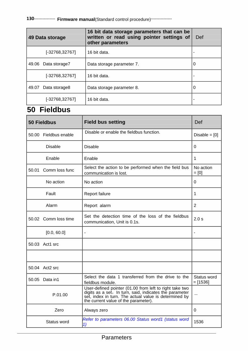
130--------------- Firmware manual(Standard control procedure)---------------
Parameters
49 Data storage 16 bit data storage parameters that can be written or read using pointer settings of other parameters
Def
[-32768,32767] 16 bit data. -
49.06 Data storage7 Data storage parameter 7. 0
[-32768,32767] 16 bit data. -
49.07 Data storage8 Data storage parameter 8. 0
[-32768,32767] 16 bit data. -
50 Fieldbus
50 Fieldbus Field bus setting Def
50.00 Fieldbus enable Disable or enable the fieldbus function.
Disable = [0]
Disable Disable 0
Enable Enable 1
50.01 Comm loss func Select the action to be performed when the field bus
communication is lost.
No action = [0]
No action No action 0
Fault Report failure 1
Alarm Report alarm 2
50.02 Comm loss time Set the detection time of the loss of the fieldbus
communication, Unit is 0.1s. 2.0 s
[0.0, 60.0] - -
50.03 Act1 src
50.04 Act2 src
50.05 Data in1 Select the data 1 transferred from the drive to the
fieldbus module.
Status word = [1536]
P.01.00
User-defined pointer (01.00 from left to right take two digits as a set,In turn, said, indicates the parameter set, index in turn. The actual value is determined by the current value of the parameter).
-
Zero Always zero 0
Status word Refer to parameters 06.00 Status word1 (status word 1)
1536

--------------- Firmware manual(Standard control procedure)--------------- 131
Parameters
50 Fieldbus Field bus setting Def
Act1
Act2
… … … …
50.16 Data in12 Select the data 12 transferred from the drive to the fieldbus module.
-
50.17 Data out1 Select the data 1 transferred from the field bus module to the drive.
Control word = [1541]
P.01.00
User-defined pointer (01.00 from left to right take two digits as a a set, indicates the parameter set, index in turn. The actual value is determined by the current value of the parameter).
-
Zero Always zero 0
Fieldbus ref1 See parameters02.15Fieldbus ref1(Field bus given 1) 527
Fieldbus ref2 See parameters02.16Fieldbus ref2(Field bus given 2) 528
Control word See parameters06.05 Control word(Control word) 1541
… … … …
50.28 Data out12 Select the data 12 transferred from the field bus
module to the drive.
Zero = [0]
51 Embedded Modbus
51 Embedded Modbus Embedded Modbus settings Def
51.00 Modbus enable Disable or enable the built-in Modbus communication function.When not in use,disable it can reduce the CPU load.
Enable = [1]
Disable Disable 0
Enable Enable 1
51.01 Node address
Set the node address of the Modbus
communication, among which 0 is the broadcast
address.
1
[0, 247] -
51.02 Baudrate Set the serial baud rate of the Modbus
communication, Unit is Bps. 9600 = [1]
4800 0
9600 1
19200 2
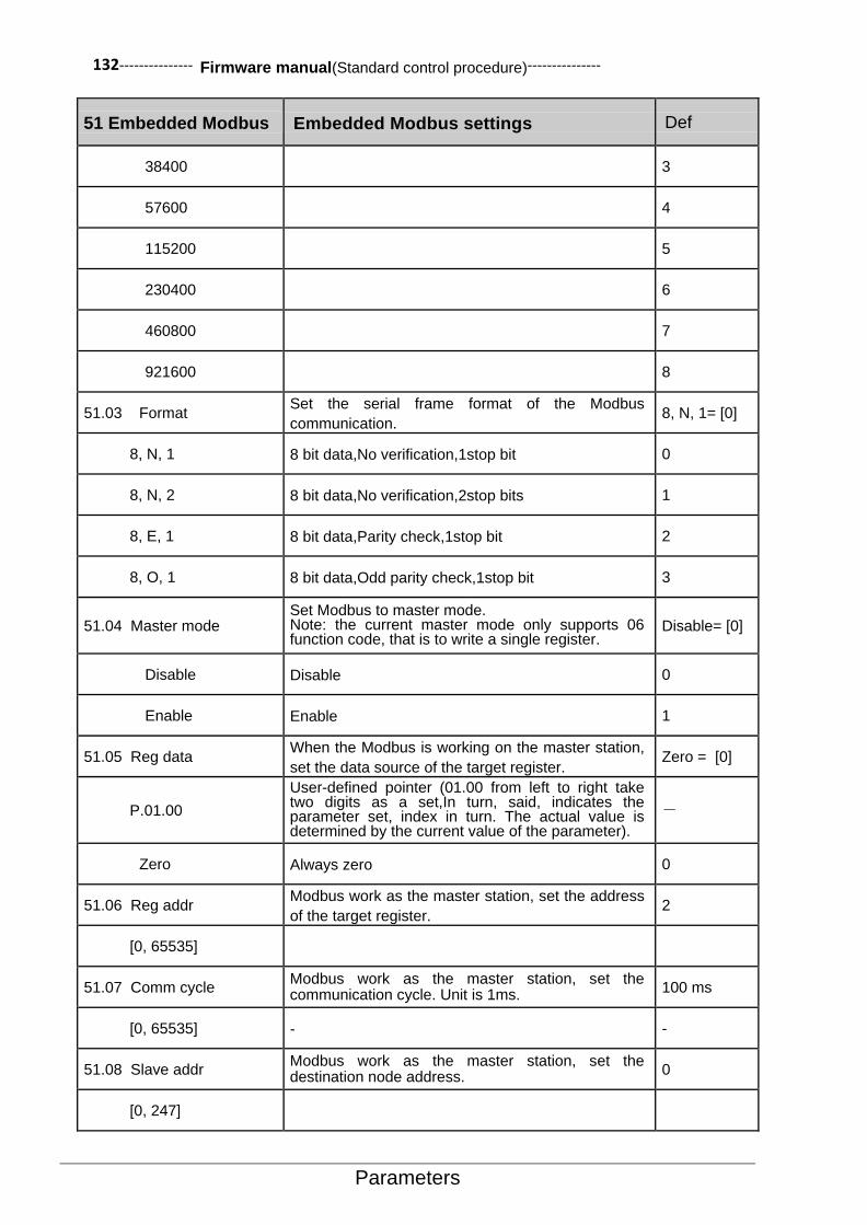
132--------------- Firmware manual(Standard control procedure)---------------
Parameters
51 Embedded Modbus Embedded Modbus settings Def
38400 3
57600 4
115200 5
230400 6
460800 7
921600 8
51.03 Format Set the serial frame format of the Modbus
communication. 8, N, 1= [0]
8, N, 1 8 bit data,No verification,1stop bit 0
8, N, 2 8 bit data,No verification,2stop bits 1
8, E, 1 8 bit data,Parity check,1stop bit 2
8, O, 1 8 bit data,Odd parity check,1stop bit 3
51.04 Master mode Set Modbus to master mode. Note: the current master mode only supports 06 function code, that is to write a single register.
Disable= [0]
Disable Disable 0
Enable Enable 1
51.05 Reg data When the Modbus is working on the master station,
set the data source of the target register. Zero = [0]
P.01.00
User-defined pointer (01.00 from left to right take two digits as a set,In turn, said, indicates the parameter set, index in turn. The actual value is determined by the current value of the parameter).
-
Zero Always zero 0
51.06 Reg addr Modbus work as the master station, set the address
of the target register. 2
[0, 65535]
51.07 Comm cycle Modbus work as the master station, set the communication cycle. Unit is 1ms.
100 ms
[0, 65535] - -
51.08 Slave addr Modbus work as the master station, set the destination node address.
0
[0, 247]

--------------- Firmware manual(Standard control procedure)--------------- 133
Parameters
51 Embedded Modbus Embedded Modbus settings Def
51.09 Diagnostics Diagnostic information for Modbus Communications. 0
51.10 Packet recv count
Count the message frames for this node received
from the Modbus bus. Note: this counter counts only
the message frames sent to this node(Broadcast
frame included)
[0, 65535]
51.11 Packet send count Count the message frames for this node sent to the
Modbus bus.
[0, 65535]
51.12 Bus message count Count all the message frames detected by this node
from the Modbus bus.
[0, 65535]
51.13 UART error count Count the number of serial port errors when the
node receives the message frame from the Modbus
bus.
[0, 65535] Normally the baud rate, frame format error, will
therefore increase the error.
51.14 CRC error count Count the number of CRC verification errors for this
node to receive messages from Modbus bus.
[0, 65535]
CRC is normally prone to errors when communication is disturbed or protocol is inconsistent. Make sure that the master-slave communication GND has been connected together.
51.15 Frame error count
Count other errors that occur when the node
receives the message frame from the Modbus bus,
such as frame length error, frame timeout, etc.
[0, 65535] Check communication agreement.

134--------------- Firmware manual(Standard control procedure)---------------
Parameters
52 CANopen
52 CANopen CANopenBus communication setup Def
52.00 node address CANopen slave node address. 0
[0, 127]
52.01 Baud rate CANopen communication baud rate 1Mbps = [8]
10k bps
0
20k bps
1
50k bps
2
125k bps
3
250k bps
4
500k bps
5
625k bps
6
800k bps
7
1M bps
8
52.02 PDO4 cfg PDO4 local configuration options Disable
Disable
0
Enable
1
52.03 RPDO4 enable RPDO4 enable Disable
Disable
0
Enable
1
52.04 RPDO4 type RPDO4 transmission type 255
[0, 255]
52.05 RPDO4 obj1 index RPDO4 Data 1 Index 0
52.06 RPDO4 obj1 subid RPDO4 Data 1 sub index 0
52.07 RPDO4 obj2 index RPDO4 Data 2 Index 0
52.08 RPDO4 obj2 subid RPDO4 Data 2 sub index 0

--------------- Firmware manual(Standard control procedure)--------------- 135
Parameters
52 CANopen CANopenBus communication setup Def
52.09 RPDO4 obj3 index RPDO4 Data 3 Index 0
52.10 RPDO4 obj3 subid RPDO4 Data 3 sub index 0
52.11 RPDO4 obj4 index RPDO4 Data 4 Index 0
52.12 RPDO4 obj4 subid RPDO4 Data 4 sub index 0
52.13 TPDO4 enable TPDO4 enable Disable
Disable
0
Enable
1
52.14 TPDO4 type TPDO4 transmission type 255
52.15 TPDO4 event time TPDO4 event timing 100
52.16 TPDO4 obj1 index TPDO4 Data 1 Index 0
52.17 TPDO4 obj1 subid TPDO4 Data 1 sub index 0
52.18 TPDO4 obj2 index TPDO4 Data 2 Index 0
52.19 TPDO4 obj2 subid TPDO4 Data 2 sub index 0
52.20 TPDO4 obj3 index TPDO4 Data 3 Index 0
52.21 TPDO4 obj3 subid TPDO4 Data 3 sub index 0
52.22 TPDO4 obj4 index TPDO4 Data 4 Index 0
52.23 TPDO4 obj4 subid TPDO4 Data 4 sub index 0
52.24 NMTstage NMT status 0
Init
0
Disable
4
Enable
5
Stand by
127
52.25 CAN error read-only. 0
52.26 CAN err counter read-only. 0

136--------------- Firmware manual(Standard control procedure)---------------
Parameters
52 CANopen CANopenBus communication setup Def
52.27 CAN RX msg cnt Count the number of the data packets received by
CAN. 0
52.28 CAN TX msg cnt Count the number of the data packets sent by
CAN. 0
52.29 DSP402 state machine DSP402 state machine. 0
Not rdy swich on
0
Switch on disable
1
Ready switch on
2
Switch on
3
Operation enable
4
Device fault
5
52.30 Control word Control word. 0
52.31 Status word Status word. 0
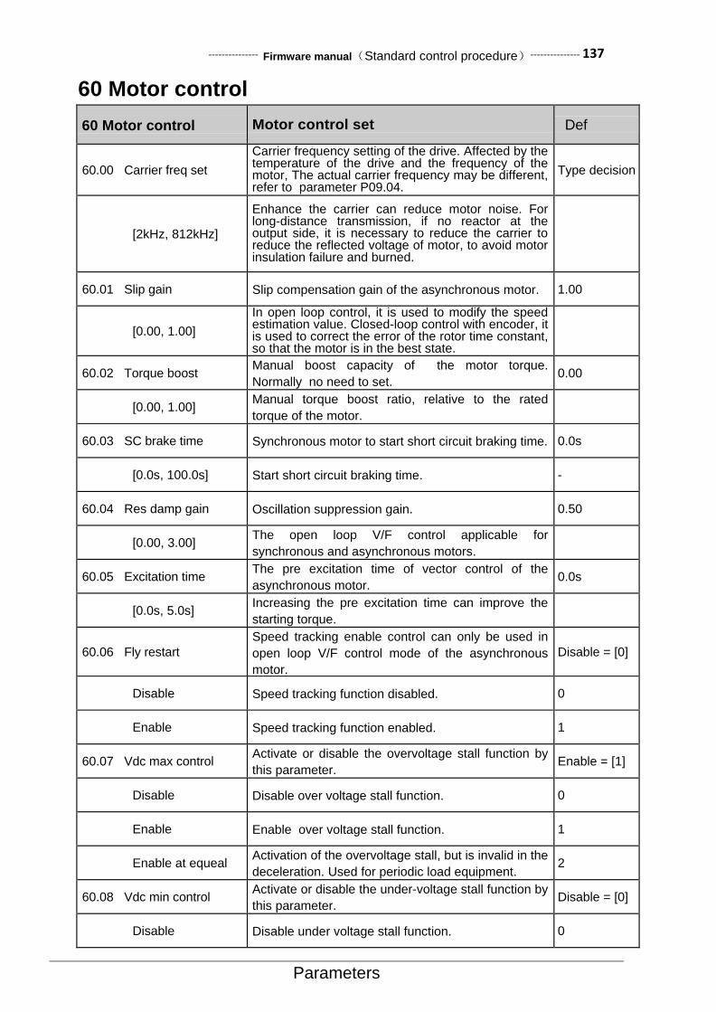
--------------- Firmware manual(Standard control procedure)--------------- 137
Parameters
60 Motor control
60 Motor control Motor control set Def
60.00 Carrier freq set
Carrier frequency setting of the drive. Affected by the temperature of the drive and the frequency of the motor, The actual carrier frequency may be different, refer to parameter P09.04.
Type decision
[2kHz, 812kHz]
Enhance the carrier can reduce motor noise. For long-distance transmission, if no reactor at the output side, it is necessary to reduce the carrier to reduce the reflected voltage of motor, to avoid motor insulation failure and burned.
60.01 Slip gain Slip compensation gain of the asynchronous motor. 1.00
[0.00, 1.00]
In open loop control, it is used to modify the speed estimation value. Closed-loop control with encoder, it is used to correct the error of the rotor time constant, so that the motor is in the best state.
60.02 Torque boost Manual boost capacity of the motor torque.
Normally no need to set. 0.00
[0.00, 1.00] Manual torque boost ratio, relative to the rated
torque of the motor.
60.03 SC brake time Synchronous motor to start short circuit braking time. 0.0s
[0.0s, 100.0s] Start short circuit braking time. -
60.04 Res damp gain Oscillation suppression gain. 0.50
[0.00, 3.00] The open loop V/F control applicable for
synchronous and asynchronous motors.
60.05 Excitation time The pre excitation time of vector control of the
asynchronous motor. 0.0s
[0.0s, 5.0s] Increasing the pre excitation time can improve the
starting torque.
60.06 Fly restart
Speed tracking enable control can only be used in
open loop V/F control mode of the asynchronous
motor.
Disable = [0]
Disable Speed tracking function disabled. 0
Enable Speed tracking function enabled. 1
60.07 Vdc max control Activate or disable the overvoltage stall function by
this parameter. Enable = [1]
Disable Disable over voltage stall function. 0
Enable Enable over voltage stall function. 1
Enable at equeal Activation of the overvoltage stall, but is invalid in the
deceleration. Used for periodic load equipment. 2
60.08 Vdc min control Activate or disable the under-voltage stall function by
this parameter. Disable = [0]
Disable Disable under voltage stall function. 0

138--------------- Firmware manual(Standard control procedure)---------------
Parameters
60 Motor control Motor control set Def
Enable Enable under voltage stall function. 1
60.09 Auto phase mode Search mode for initial phase of the synchronous
motor. Auto = [0]
Auto Enable automatically. Normally performs after power
up and coast stop. 0
Always Always enable the phase search function. 1
Disable Always disable the phase search function. 2
60.10 PM type
The rotor type of the synchronous motor. The change of the search mode caused by the structure of the rotor.
[1]
Type 1 non standard
Special phase search mode, suitable for partially
embedded motor, such as squirrel cage motor. 0
Type 2 standard type
Standard phase search method , Suitable for
surface mount motors and most embedded motors 1
60.11 Cur inject
Synchronous motor phase to find the size of the injected current. For the case of a synchronous motor with squirrel cage, as well as big rating drive control small rating motor, needs to be slightly increased.
30%
[0, 100]
60.12 Phase comp
The phase compensation value of the synchronous
motor. For quick start application 90°is the best,
while ordinary start 30°is the best。Normally set in
the range of 0 to 90°.
30deg
[-180, 180]
60.13 Over modu gain Over modulation output intensity。 15%
[0, 15]
60.14 PWM mode PWM modulation mode. THD = [0]
AUTO THD The PWM mode is automatically adjusted to
minimize the output voltage harmonics. 0
AUTO SL The PWM mode is automatically adjusted to
minimize the IGBT switching loss. 1
SVPWM SVPWM represents a continuous PWM mode,
DPWM means intermittent PWM mode. 2
DPWM MIN DPWM MIN mode, micro drive series driver does not
support DPWM mode. 3
DPWM MAX DPWM MAX mode 4
DPWM3 DPWM3 mode 5
DPWM2 DPWM2 mode 6
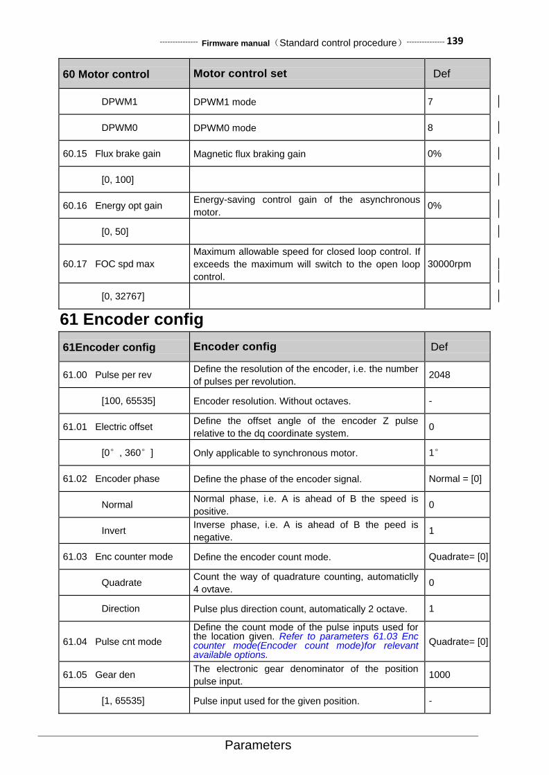
--------------- Firmware manual(Standard control procedure)--------------- 139
Parameters
60 Motor control Motor control set Def
DPWM1 DPWM1 mode 7
DPWM0 DPWM0 mode 8
60.15 Flux brake gain Magnetic flux braking gain 0%
[0, 100]
60.16 Energy opt gain Energy-saving control gain of the asynchronous
motor. 0%
[0, 50]
60.17 FOC spd max
Maximum allowable speed for closed loop control. If
exceeds the maximum will switch to the open loop
control.
30000rpm
[0, 32767]
61 Encoder config
61Encoder config Encoder config Def
61.00 Pulse per rev Define the resolution of the encoder, i.e. the number
of pulses per revolution. 2048
[100, 65535] Encoder resolution. Without octaves. -
61.01 Electric offset Define the offset angle of the encoder Z pulse
relative to the dq coordinate system. 0
[0°, 360°] Only applicable to synchronous motor. 1°
61.02 Encoder phase Define the phase of the encoder signal. Normal = [0]
Normal Normal phase, i.e. A is ahead of B the speed is
positive. 0
Invert Inverse phase, i.e. A is ahead of B the peed is
negative. 1
61.03 Enc counter mode Define the encoder count mode. Quadrate= [0]
Quadrate Count the way of quadrature counting, automaticlly
4 ovtave. 0
Direction Pulse plus direction count, automatically 2 octave. 1
61.04 Pulse cnt mode
Define the count mode of the pulse inputs used for the location given. Refer to parameters 61.03 Enc counter mode(Encoder count mode)for relevant available options.
Quadrate= [0]
61.05 Gear den The electronic gear denominator of the position
pulse input. 1000
[1, 65535] Pulse input used for the given position. -

140--------------- Firmware manual(Standard control procedure)---------------
Parameters
61Encoder config Encoder config Def
61.06 Gear num The electronic gear molecule of the position pulse
input. 1000
[1, 65535] Pulse input used for the given position. -
61.07 Encoder enable The enable encoder module, can only be used for
small micro series driver. Disable = [0]
Disable Disable encoder function. 0
Enable Enable encoder function. 1
62 Motor parameter
62 Motor parameter Motor parameter setting Def
62.00 Pole pairs
The pole number of the motor. Calculate
automatically before drive running. The correct
setting of the rated speed and rated frequency is the
premise of correct calculation.
Model correlation
[1, 30] The pole number of the motor. Applicable to all types
of AC motors. -
62.01 No-load current
No-load current of the asynchronous motor. When
using the synchronous motor, this parameter is
retained.
Model correlation
[0A, 400.0A] This parameter is usually obtained by auto tuning.
You can also manually set.
62.02 Stator resist Stator phase resistance of motor. Applicable to all
types of AC motors.
Model correlation
[0Ω, 65.535Ω] This parameter is usually obtained by auto tuning,
You can also manually set.
62.03 Rotor resist Rotor phase resistance of motor. Only for induction
motors.
Model correlation
[0Ω, 65.535Ω] This parameter is usually obtained by auto tuning,
You can also manually set.
62.04 Stator induct Stator phase inductance of electric machine. Model correlation
[0mH, 3000.0mH] This parameter is usually obtained by auto tuning,
You can also manually set.
62.05 Leak induct coef Leakage inductance coefficient of electric machine。
Only for induction motors.
Model correlation
[0%, 20.0%] This parameter is usually obtained by auto tuning.
You can also manually set.
62.06 d-axis induct D axis inductance. Only applicable to synchronous
motor.
Model correlation
[0.00mH, 300.00mH]
This parameter is usually obtained by auto tuning.
You can also manually set.
62.07 q-axis induct q axis inductance。Only applicable to synchronous
motor。
Model correlation
[0.00mH, 300.00mH]
This parameter is usually obtained by auto tuning.
You can also manually set.

--------------- Firmware manual(Standard control procedure)--------------- 141
Parameters
62 Motor parameter Motor parameter setting Def
62.08 Back EMF coef Back EMF coefficient of synchronous motor, only applicable to synchronous motor. Automatic correction during drive operation.
Model correlation
[0.0mV, 3000.0mV] This parameter is usually obtained by auto tuning.
You can also manually set. 0.1mV/rpm
62.09 Core sat coef Iron core saturation coefficient of electric machine. 80%
[50, 100] This parameter is usually obtained by auto tuning.
You can also manually set.
62.10 PM with squirrel Synchronous motor with a squirrel cage for 1, auto
tuning can be obtained. 0
[50, 100] This parameter is usually obtained by auto tuning.
You can also manually set.
63 Startup parameter
63 Startup parameter Start Related Parameter Settings Def
63.00 Motor nom power
Define motor rated power.This setting must be consistent with the motor nameplate value.If one drive control the multi motors, input motor total
power. Be careful:When the drive is running, this
parameter cannot be changed.
Default values depend on Models
[0.00kW, 630.00 kW] -
63.01 Motor nom volt
The rated motor voltage is defined as the root mean square voltage between the basic lines supplied to the motor at the rated operating point.This setting must be consistent with the motor nameplate value.
Be careful:
• For permanent magnet motors, means the rated speed of the back EMF. Do not need very accurate, because the drive automatic recognition of back EMF in operation.
• When the drive is running, the parameter cannot be changed.
Default values dependon Models
[0 V, 1000 V]
63.02 Motor nom current
Define motor rated current.The value must be equal to the motor nameplate.If the drive control multi motors, input motor total current. Be careful: • The correct operation of the motor requires no
more than ninety percent of the rated current of the drive.
• When the drive is running,This parameter cannot be changed.
Default values depend on Models
[0.0 A, 1200.0 A]
63.03 Motor nom speed
Define motor rated speed.This setting must be consistent with the motor nameplate value.
Be careful : When the drive is running, this
parameter cannot be changed.
Default values depend on Models

142--------------- Firmware manual(Standard control procedure)---------------
Parameters
63 Startup parameter Start Related Parameter Settings Def
[0 RPM, 30000 RPM]
63.04 Motor nom freq
Define motor rated frequency.
Be careful : When the drive is running, the
parameter cannot be changed.
50Hz
[0 Hz, 1000 Hz]
63.05 Motor type Select motor type. Be careful:When the drive is
running, the parameter cannot be changed. ACIM = [0]
ACIM Asynchronous motor, three phase AC induction motor, Squirrel cage rotor.
0
PMSM Permanent magnet motor.Three phase AC synchronous motor, Permanent magnet rotor and sinusoidal back EMF voltage.
1
SynRM Synchronous reluctance motor.Three phase AC synchronous motor with non permanent salient pole rotor.
2
63.06 ID run request
Select the drive at the next startup motor to identify the type of operation. After completion of the auto tuning of motor, drive will stop. Notice:When the drive is running, this parameter cannot be changed. Once activated the auto tuning, you must stop the drive first, and then stop auto tuning. Notice: • The auto tuning can only be performed in local
control mode (The drive is controlled by a PC tool or control panel).
• Must be identified in the auto tuning process,Safety torque interrupt and emergency stop circuit must be closed.
No request = [0]
No request No motor auto tuning operation required。 0
Normal
Normal operation of auto tuning. Ensure that in all cases have good control accuracy. Auto tuning run for continued 90 seconds. Under normal circumstances, this mode should be selected. Notice: • In the following two cases to perform routine
auto tuning. Must disconnect the mechanical connection between motor and driven equipment : If the load torque is higher than 20%; If the mechanical device driven by the motor is not able to withstand the rated speed transients during the normal auto tuning operation.
• Before starting auto tuning,please check the motor turn. During auto tuning, motor will be forward。
Warning!Motor in the running speed can reach about 50... 100% of rated speed. Before the start auto tuning operation, please confirm whether can ensure safety.
1
Standstill
Static auto tuning operation. Motor power into the dc or ac current. For asynchronous motors, the motor will not turn(For permanent magnet motor and synchronous reluctance motor,motor rotation travel less than half turn) . Notice:Only by the influence of the connected mechanical parts,can not conduct Normal auto tuning run time, select the mode(For example, the rising edge of activation or lift applications) .
2
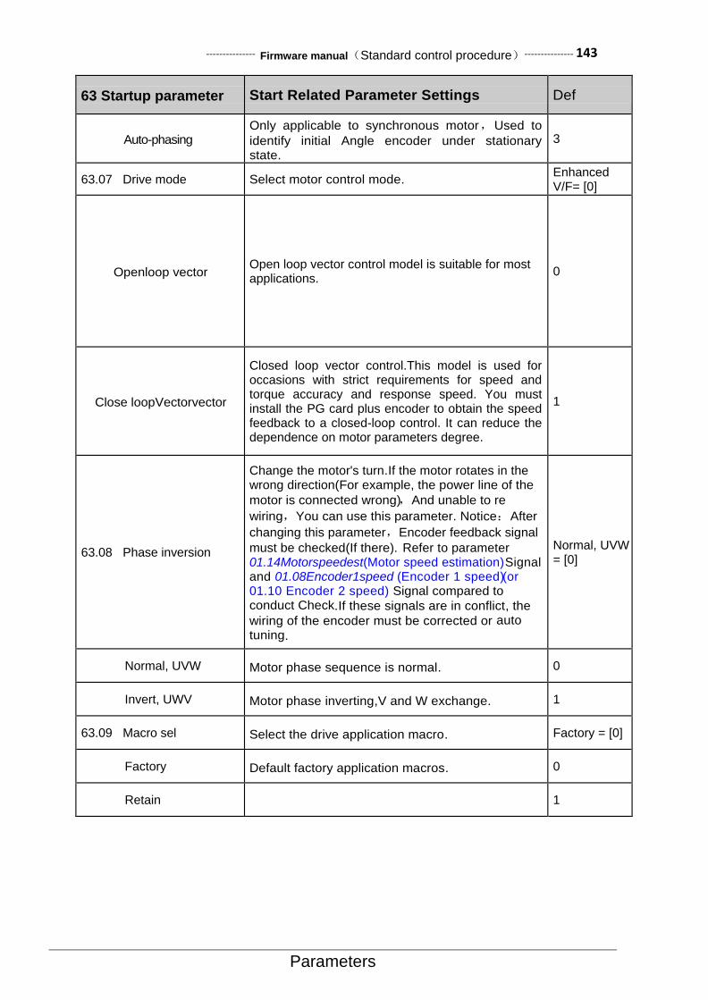
--------------- Firmware manual(Standard control procedure)--------------- 143
Parameters
63 Startup parameter Start Related Parameter Settings Def
Auto-phasing Only applicable to synchronous motor,Used to
identify initial Angle encoder under stationary state.
3
63.07 Drive mode Select motor control mode. Enhanced V/F= [0]
Openloop vector Open loop vector control model is suitable for most applications.
0
Close loopVectorvector
Closed loop vector control.This model is used for occasions with strict requirements for speed and torque accuracy and response speed. You must install the PG card plus encoder to obtain the speed feedback to a closed-loop control. It can reduce the dependence on motor parameters degree.
1
63.08 Phase inversion
Change the motor's turn.If the motor rotates in the wrong direction(For example, the power line of the
motor is connected wrong) ,And unable to re
wiring,You can use this parameter. Notice:After
changing this parameter,Encoder feedback signal
must be checked(If there). Refer to parameter 01.14Motorspeedest(Motor speed estimation)Signal and 01.08Encoder1speed (Encoder 1 speed) (or 01.10 Encoder 2 speed) Signal compared to conduct Check.If these signals are in conflict, the
wiring of the encoder must be corrected or auto
tuning.
Normal, UVW = [0]
Normal, UVW Motor phase sequence is normal. 0
Invert, UWV Motor phase inverting,V and W exchange. 1
63.09 Macro sel Select the drive application macro. Factory = [0]
Factory Default factory application macros. 0
Retain 1

144--------------- Firmware manual(Standard control procedure)---------------
Field bus
6. Field Bus data set
Address Name
0001 Fieldbus control word (corresponding to monitoring parameter address 6.05)
0002 Field bus given 1(corresponding to monitoring parameter address02.15)
0003 Field bus given 2(corresponding to monitoring parameter address02.16)
0004 Field bus status word
0005 Field bus actual value1
0006 Field bus actual value2
0007-0018 Field bus module input1-12(parameter50.05-50.16)
0019-0030 Field bus module output1-12(parameter50.17-50.28)
Fieldbus control word can be viewed by parameter 6.05,Please refer to this manual before.
【Field bus status word format】 No. Name Meaning
0 Ready 1:Operationalreadiness
1 Enabled 1:Run enable
2 Modulating 1:PWM signal output
3 Following ref 1:
4 Em OFF2 1:Free parking mode
5 Em OFF3 1:Emergency stop mode
6 Start inhibit 1:Start inhibit
7 Alarm 1:Alarm
8 At setpoint 1:The output is consistent with the set (speed arrival or torque arrival)
9 Torque limited 1:Torque limited
10 Speed limited 1:Speed limited
11 EXT2 active 1:Control ground 2 effective
12 Local ctrl 1:Local ctrl
13 Zero speed 1:Zero speed
14 Direction reverse 1:Direction reverse
15 Fault 1:Fault
【Related parameters】 parameter address
parameter name parameter values
51.00 Modbus enable Enable = [1]
51.01 Node address -
51.02 Baudrate -
51.03 Format -
【Sample】 The following is an example of node address equal to 1,The last CRC check code is only applicable to this case,To change any data should be recalculated after CRC check code,Can use the software automatically generated.
1、 Read drive status
Request frame:01 03 06 00 00 01 84 82
Response frame:01 03 02 B4 81 0F 24

--------------- Firmware manual(Standard control procedure)--------------- 145
Field bus
2、 Modify drive given speed(First, the signal source for the given speed is field bus
3、 given 1)
Request frame:01 06 00 02 03 E8 28 B4 Response frame
4、 boot drive(Modify the external control to start first、Stop command signal source for fieldbus communication)
Request frame:01 06 00 01 08 82 5F AB
(Where 0x0882 for startup command,Note that bit 7 and bit 11 must always be maintained at a level of 1)
Response frame slightly
5、 Stop driver
Request frame:01 06 00 01 08 81 1F AA (Where 0x0881 is a shutdown command,Note that bit 7 and bit 11 must always be maintained at a level of 1) Response frame slightly
6、 Read parameter 22.00Acc time1(Acceleration time 1)Attribute
Request frame:01 42 0000 1600 77 A5
Response frame:01 42 00 0008 AC 7E 78
7、 Read parameter22.00Acc time1(Acceleration time 1)Default value
Request frame:01 42 0001 1600 26 65
Response frame:01 42 000101 F4 28 12
8、 Read parameter 22.01 Dec time1(Deceleration time 1)Minimum value
Request frame:01 42 00 02 16 01 17 A5
Response frame:01 42 00 02 00 01 19 C5
9、 Read parameter 22.01 Dec time1(Deceleration time 1)Maximum value of
Request frame:01 42 00 03 16 01 46 65
Response frame:01 42 00 03 EA 60 C6 8D
10、 Read parameter 01 Actual values(actual value)Containednumber of parameters
Request frame:01 42 00 04 16 01 F7 A4
Response frame:01 42 00 04 00 0D F9 C1
Address Name
0001 Field bus control word(Corresponding monitoring parameter address06.05)
0002 Field bus given1(Corresponding monitoring parameter address02.15)
0003 Field bus given2(Corresponding monitoring parameter address02.16)
0004 Field bus status word
0005 Field bus actual value1
0006 Field bus actual value2
Field bus control word
No. Name Meaning
0 Stop 1:Stop
1 Start 0->1:start-up
2 Em OFF2 1:Select the free parking mode(The bit 0 must be set to 1)
3 Em OFF3 1:Select emergency stop mode(The bit 0 must be set to 1)
4 Loc ctrl req 1:Local control request
5 Ramp stop 1:Select deceleration stop mode(The bit 0 must be set to 1)
6 Coast stop 1:Free parking mode(The bit 0 must be set to 1)
7 Run enable 1:Run enable

146--------------- Firmware manual(Standard control procedure)---------------
Field bus
8 Reset 0->1:Reset fault
9 JOG1 0->1:Move 1
10 JOG2 0->1:Move 2
11 Remote 1:Remote control
12
13
14
15 EXT2 sel 1:Selective control 2
Field bus status word
No. Name Meaning
0 Ready 1:Operational readiness
1 Enabled 1:Run enable
2 Modulating 1:PWM signal output
3 Following ref 1:
4 Em OFF2 1:Free parking mode
5 Em OFF3 1:Emergency stop mode
6 Start inhibit 1:Start inhibit
7 Alarm 1:Alarm
8 At setpoint 1:The output is consistent with the set (speed arrival or torque arrival)
9 Torque limited 1:Torque limiter
10 Speed limited 1:Speed limiting
11 EXT2 active 1:Control ground 2 effective
12 Local ctrl 1:Local control
13 Zero speed 1:Zero speed
14 Direction reverse 1:Reversal
15 Fault 1:Fault
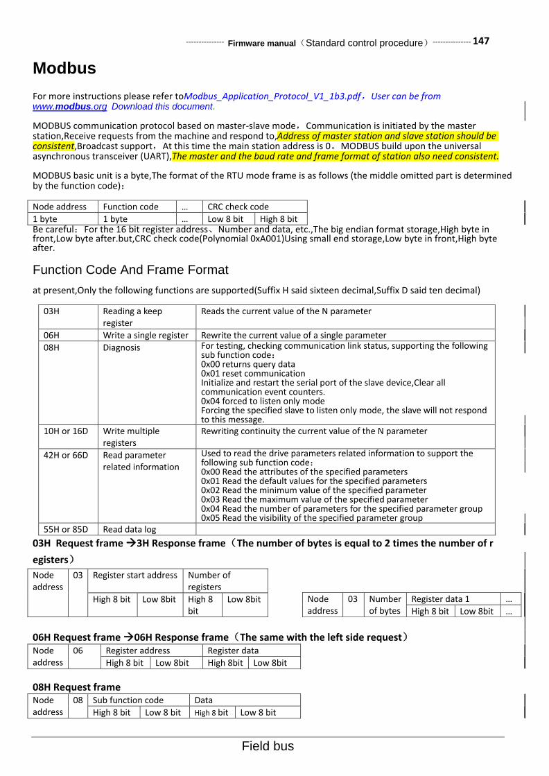
--------------- Firmware manual(Standard control procedure)--------------- 147
Field bus
Modbus
For more instructions please refer toModbus_Application_Protocol_V1_1b3.pdf,User can be from www.modbus.org Download this document.
MODBUS communication protocol based on master-slave mode,Communication is initiated by the master station,Receive requests from the machine and respond to,Address of master station and slave station should be consistent,Broadcast support,At this time the main station address is 0。MODBUS build upon the universal asynchronous transceiver (UART),The master and the baud rate and frame format of station also need consistent.
MODBUS basic unit is a byte,The format of the RTU mode frame is as follows (the middle omitted part is determined by the function code):
Node address Function code … CRC check code
1 byte 1 byte … Low 8 bit High 8 bit Be careful:For the 16 bit register address、Number and data, etc.,The big endian format storage,High byte in front,Low byte after.but,CRC check code(Polynomial 0xA001)Using small end storage,Low byte in front,High byte after.
Function Code And Frame Format
at present,Only the following functions are supported(Suffix H said sixteen decimal,Suffix D said ten decimal)
03H Reading a keep register
Reads the current value of the N parameter
06H Write a single register Rewrite the current value of a single parameter
08H Diagnosis For testing, checking communication link status, supporting the following sub function code: 0x00 returns query data 0x01 reset communication Initialize and restart the serial port of the slave device,Clear all communication event counters. 0x04 forced to listen only mode Forcing the specified slave to listen only mode, the slave will not respond to this message.
10H or 16D Write multiple registers
Rewriting continuity the current value of the N parameter
42H or 66D Read parameter related information
Used to read the drive parameters related information to support the following sub function code: 0x00 Read the attributes of the specified parameters 0x01 Read the default values for the specified parameters 0x02 Read the minimum value of the specified parameter 0x03 Read the maximum value of the specified parameter 0x04 Read the number of parameters for the specified parameter group 0x05 Read the visibility of the specified parameter group
55H or 85D Read data log
03H Request frame 3H Response frame(The number of bytes is equal to 2 times the number of r
egisters)
Node address
03 Register start address Number of registers
High 8 bit Low 8bit High 8 bit
Low 8bit
06H Request frame 06H Response frame(The same with the left side request) Node address
06 Register address Register data
High 8 bit Low 8bit High 8bit Low 8bit
08H Request frame Node address
08 Sub function code Data
High 8 bit Low 8 bit High 8 bit Low 8 bit
Node address
03 Number of bytes
Register data 1 …
High 8 bit Low 8bit …

148--------------- Firmware manual(Standard control procedure)---------------
Field bus
10H Request frame(The number of bytes is equal to 2 times the number of registers) Node address
10 Register start address
Number of registers
Number of bytes
Register data 1 …
High 8 bit
Low 8 bit
High 8 bit
Low 8 bit
High 8 bit
Low 8 bit
…
10H Response frame(Returns the first 6 bytes of the request frame)
42H Request frame Node address
42 Sub function code Parameter address
High 8 bit
Low 8 bit High 8 bit
Low 8 bit
42H Response frame
Node address
42 Sub function code Parameter information
High 8 bit
Low 8 bit High 8 bit
Low 8 bit
Parameter address Parameter address is 16 bits,High 8 bit parameter group number,Low 8 bit is within the group index。
GROUP INDEX Address
Hexadecimal Decimal system
00 Communication data 01-30 Data set 0001-001E 0001-0030
01 Parameter group 01 00- 255 Parameter 01.00-01.255 0100-01FF 256-511
02 Parameter group 02 00- 255 Parameter 02.00-02.255 0200-02FF 512-767
… … … …
63 Parameter group 63 00- 255 Parameter 63.00-63.255 3F00-3FFF 16128-16383
Notice:
1、For each actual parameter, please refer to this manual.
2、The use of PLC as the main station parameter address need to add 40000,If the communication address of parameter 01.00 is 40256.
Notice:For more instructions please refer toModbus_Application_Protocol_V1_1b3.pdf,User can be from
www.modbus.org Download this document.
Function code list
Function code
Name Describe
0x03 Read hold register Read one or more parameters
0x06 Write a single register Write a single parameter
0x08 Diagnosis For testing, check the communication between the master station and the slave station, only support the following sub function code: 0x01 reset communication Initialize and restart the serial port of the slave device, clear all communication event counters. 0x04 Force to listen only mode. Forcing the specified slave to listen only mode, the slave will not respond to this message.
0x10 Write multiple registers Write continuous multiple parameters
0x42 Read parameter related information
The information used to read the drive parameters is currently only
supported by the following sub function code: 0x01 Read the attributes of the specified parameters 0x02 Read the default values for the specified parameters 0x03 Read the minimum value of the specified parameter 0x04 Read the maximum value of the specified parameter 0x05 Read the number of parameters for the specified parameter group 0x06 Read the visibility of the specified parameter group

--------------- Firmware manual(Standard control procedure)--------------- 149
Field bus
Related parameters
Parameter address
Parameter name parameter values
51.00 Modbus enable Enable = [1]
51.01 Node address -
51.02 Baudrate -
51.03 Format -
Sample description (sixteen decimal)
11、 Read drive status
Request frame format:01 03 06 00 00 01 84 82
(Among 0x0600 Namely representation parameter 06.00 Status word1(Status word 1))
Response frame format:01 03 02 B4 81 0F 24
(Among 0xB481 Current status for the drive)
Modify the given speed of the drive (first modify the speed of the given signal source for the fieldbus given 1)
Request frame format:01 06 00 0203E8 28 B4
(Among 0x0002 It indicates that the fieldbus given 1,0x03E8 Express 1000RPM)
Response frame slightly
12、 Boot drive(Start by modifying the external control、Stop command signal source for fieldbus communication)
Request frame format:01 06 00 01 08 82 5F AB
(Among 0x0001 Namely representation fieldbus control word,0x0882 Start command,Note that bit 7 and bit 11
must always be maintained at a level of 1)
Response frame slightly
13、 Stop driver
Request frame format:01 06 00 01 08 81 1F AA
(Among 0x0001 Namely representation fieldbus control word,0x0881 Stop command,Note that bit 7 and bit 11
must always be maintained at a level of 1)
Response frame slightly
14、 Read parameter 22.01 Dec time1(Deceleration time 1)Maximum value of
Request frame format:01 42 00 04 16 01 F7 A4
(Among 0x0004 Represents the maximum value of the specified parameter,0x1601 Specified parameter 22.01
Dec time1(Deceleration time 1))
Response frame format:01 42 00 04 FF FF39B4
(Among 0xFFFFThe maximum value of the deceleration time 1,Here for 655.35s)
15、 Read parameter set 01 Actual values(actual value)Number of parameters
Request frame format:01 42 00 05 01 00 68 54 (The underlined 00 representation can be any value)
(Among 0x0005 The number of parameters to read the specified parameter group,0x01 Specified parameter
group 01 Actual values(actual value))
Response frame format:01 42 00 05001F28 0C
(Among 0x001F Parametric array 01 Actual valuesContain
number of parameters,Here for 31)

150--------------- Firmware manual(Standard control procedure)---------------
Fault tracking and processing Fieldbus
CANopen
CANopen Protocol introduction CANopen Protocol based on CAN protocol,The CAN protocol defines the first layer of the OSI reference
model in the seven layer(physical layer)And the second layer(data link layer)Norm,CANopenDefines the seventh layer (application layer) specification.CANopenProtocols can be applied to multiple industries,This manual only describes the CANopen protocol used in the drive control industry information. A detailed description of the CAN,Please refer to the documentBOSCH Controller Area Network(CAN) Specification V2.0.
A detailed description of the CANopen,Please refer to the following documents:
1、DS 301 Application Layer and Communication Profile(The application layer and the communication rules)
2、DSP 402 Device Profile for Drives and Motion Control(Drive and motion control equipment industry)
3、DS 306 Electronic Data Sheet Specification for CANopen(EDS file specification)
Communication object
【Communication identifier】
When using the CAN2.0A protocol,Communication identifier COB-ID is 11 bits,The CAN device filters the
message through this identifier.The encoding format is as follows (Notes:Node address valid Value range
1~127):
b10 b9 b8 b7 b6 b5 b4 b3 b2 b1 b0
Function code Node address
Communication object Function code(Binary) COB-ID(Hexadecimal)
NMT 0000 000
SYNC 0001 080
EMERGENCY 0001 081~0FF
TIME STAMP 0010 100
TPDO1 0011 181~1FF
RPDO1 0100 201~27F
TPDO2 0101 280~2FF
RPDO2 0110 301~37F
TPDO3 0111 381~3FF
RPDO3 1000 401~47F
TPDO4 1001 481~4FF
RPDO4 1010 501~57F
Download SDO 1011 581~5FF
Upload SDO 1100 601~67F
NMTE 1110 701~77F
【frame format】
CAN2.0 standard up to 8 bytes of data transmission,First bytes before the most,Eighth bytes at
last.Therefore,CANopen Message frame format is as follows:
Frame head
1st byte 2nd byte 3rd byte 4th byte 5th byte 6th byte 7th byte 8th byte
Notes:CAN device uses a high priority way to transmit a single byte,First transmission bit 7,Last
transmission bit 0.
【Frame head】
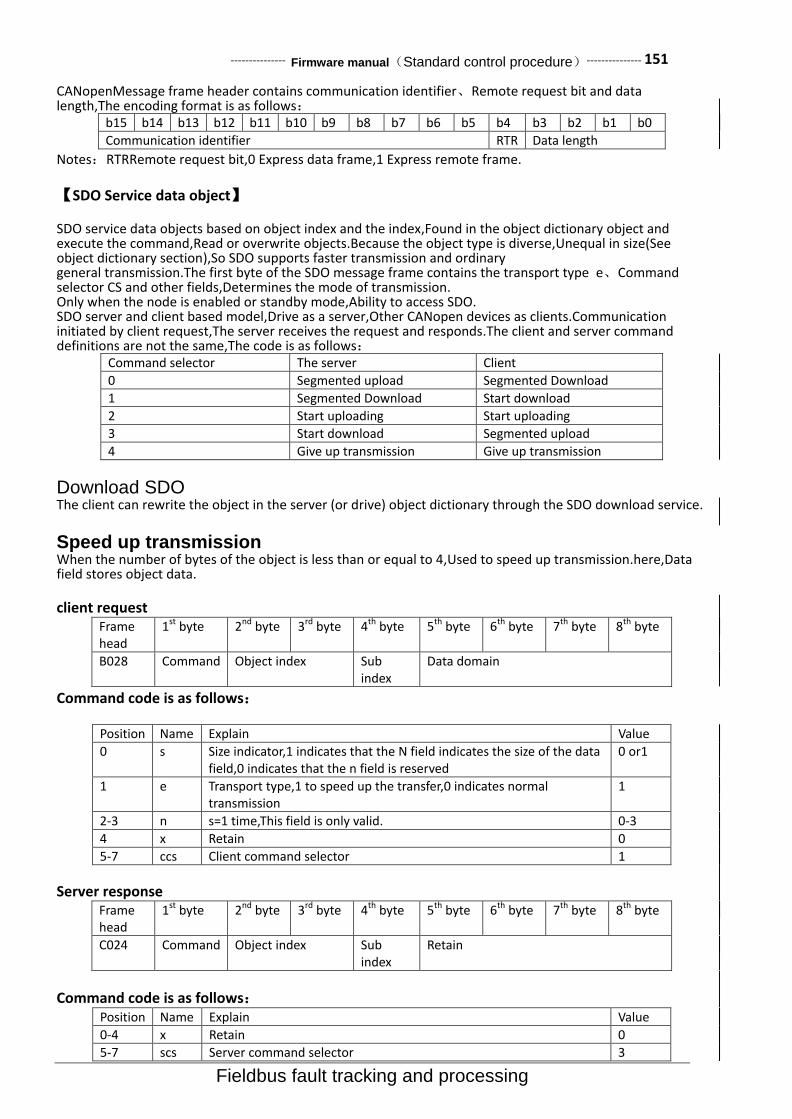
--------------- Firmware manual(Standard control procedure)--------------- 151
Fieldbus fault tracking and processing
CANopenMessage frame header contains communication identifier、Remote request bit and data length,The encoding format is as follows:
b15 b14 b13 b12 b11 b10 b9 b8 b7 b6 b5 b4 b3 b2 b1 b0
Communication identifier RTR Data length
Notes:RTRRemote request bit,0 Express data frame,1 Express remote frame.
【SDO Service data object】
SDO service data objects based on object index and the index,Found in the object dictionary object and execute the command,Read or overwrite objects.Because the object type is diverse,Unequal in size(See object dictionary section),So SDO supports faster transmission and ordinary general transmission.The first byte of the SDO message frame contains the transport type e、Command selector CS and other fields,Determines the mode of transmission. Only when the node is enabled or standby mode,Ability to access SDO. SDO server and client based model,Drive as a server,Other CANopen devices as clients.Communication initiated by client request,The server receives the request and responds.The client and server command definitions are not the same,The code is as follows:
Command selector The server Client
0 Segmented upload Segmented Download
1 Segmented Download Start download
2 Start uploading Start uploading
3 Start download Segmented upload
4 Give up transmission Give up transmission
Download SDO The client can rewrite the object in the server (or drive) object dictionary through the SDO download service.
Speed up transmission When the number of bytes of the object is less than or equal to 4,Used to speed up transmission.here,Data field stores object data.
client request Frame head
1st byte 2nd byte 3rd byte 4th byte 5th byte 6th byte 7th byte 8th byte
B028 Command Object index Sub index
Data domain
Command code is as follows:
Position Name Explain Value
0 s Size indicator,1 indicates that the N field indicates the size of the data field,0 indicates that the n field is reserved
0 or1
1 e Transport type,1 to speed up the transfer,0 indicates normal transmission
1
2-3 n s=1 time,This field is only valid. 0-3
4 x Retain 0
5-7 ccs Client command selector 1
Server response Frame head
1st byte 2nd byte 3rd byte 4th byte 5th byte 6th byte 7th byte 8th byte
C024 Command Object index Sub index
Retain
Command code is as follows: Position Name Explain Value
0-4 x Retain 0
5-7 scs Server command selector 3

152--------------- Firmware manual(Standard control procedure)---------------
Fault tracking and processing Fieldbus
Ordinary transmission
【Start download】 When the number of bytes exceeds 4 bytes,The client uses the common transmission,Notification will be downloaded to the server(Namely drive)Number of bytes of the object。here,The number of bytes stored in the data field.
Client request Frame head
1st byte 2nd byte 3rd byte 4th byte 5th byte 6th byte 7th byte 8th byte
B028 Command Object index Sub index
Data domain
Command code is as follows: Position Name Explain Value
0 s Size indicator,1 indicates that the N field indicates the size of the data field,0 indicates that the n field is reserved
0 Or1
1 e Transport type,1 to speed up the transfer,0 indicates normal transmission
0
2-3 n s=1 time,This field is only valid. 0-3
4 x Retain. 0
5-7 ccs Client command selector. 1
The server response and speed up the transfer the same.
【Subsection Download】
After the server (Namely drive) correctly receives the number of bytes in the object,The client is in a byte
order from low to high,Using segmented transmission in turn up to 7 bytes of data segment.
client request Frame head
1st byte 2nd byte 3rd byte 4th byte 5th byte 6th byte 7th byte 8th byte
B028 Command Segment data
Command code is as follows: Position Name Explain Value
0 c End indicator,1 said the end of the segmented Download. 0 Or 1
1-3 n The nonzero n value indicates that the last n bytes of the message frame do not contain data.
0-7
4 t Turning and turning,The first segment message frame will clear this bit 0,After each segmented message frame will this turn.
5-7 ccs Client command selector 0
Server response Frame head
1st byte 2nd byte 3rd byte 4th byte 5th byte 6th byte 7th byte 8th byte
C021 Command Retain
Command code is as follows: Position Name Explain Value
0-3 x Retain 0
4 t Turning and turning
5-7 scs Server command selector 1
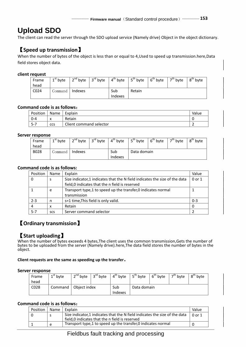
--------------- Firmware manual(Standard control procedure)--------------- 153
Fieldbus fault tracking and processing
Upload SDO The client can read the server through the SDO upload service (Namely drive) Object in the object dictionary.
【Speed up transmission】
When the number of bytes of the object is less than or equal to 4,Used to speed up transmission.here,Data
field stores object data.
client request Frame head
1st byte 2nd byte 3rd byte 4th byte 5th byte 6th byte 7th byte 8th byte
C024 Command Indexes Sub Indexes
Retain
Command code is as follows: Position Name Explain Value
0-4 x Retain 0
5-7 ccs Client command selector 2
Server response Frame head
1st byte 2nd byte 3rd byte 4th byte 5th byte 6th byte 7th byte 8th byte
B028 Command Indexes Sub Indexes
Data domain
Command code is as follows: Position Name Explain Value
0 s Size indicator,1 indicates that the N field indicates the size of the data field,0 indicates that the n field is reserved
0 or 1
1 e Transport type,1 to speed up the transfer,0 indicates normal transmission
1
2-3 n s=1 time,This field is only valid. 0-3
4 x Retain 0
5-7 scs Server command selector 2
【Ordinary transmission】
【Start uploading】 When the number of bytes exceeds 4 bytes,The client uses the common transmission,Gets the number of bytes to be uploaded from the server (Namely drive).here,The data field stores the number of bytes in the object.
Client requests are the same as speeding up the transfer。
Server response Frame head
1st byte 2nd byte 3rd byte 4th byte 5th byte 6th byte 7th byte 8th byte
C028 Command Object index Sub Indexes
Data domain
Command code is as follows: Position Name Explain Value
0 s Size indicator,1 indicates that the N field indicates the size of the data field,0 indicates that the n field is reserved
0 or 1
1 e Transport type,1 to speed up the transfer,0 indicates normal 0
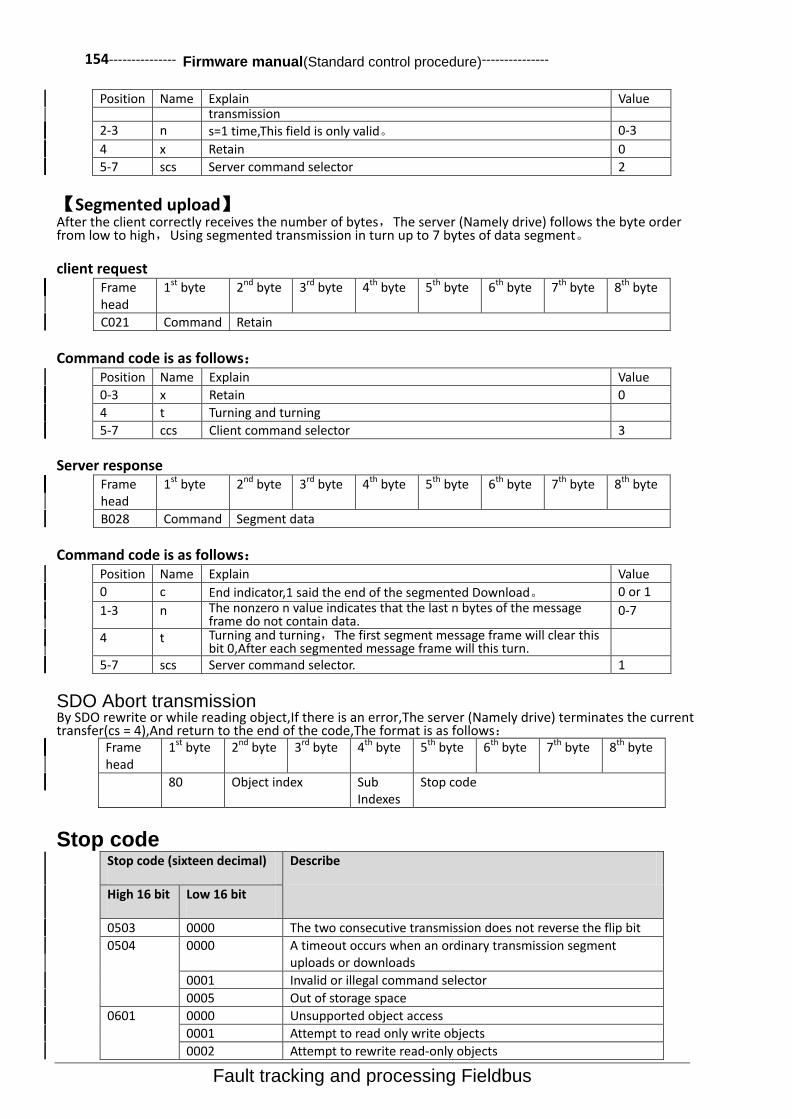
154--------------- Firmware manual(Standard control procedure)---------------
Fault tracking and processing Fieldbus
Position Name Explain Value transmission
2-3 n s=1 time,This field is only valid。 0-3
4 x Retain 0
5-7 scs Server command selector 2
【Segmented upload】 After the client correctly receives the number of bytes,The server (Namely drive) follows the byte order from low to high,Using segmented transmission in turn up to 7 bytes of data segment。
client request Frame head
1st byte 2nd byte 3rd byte 4th byte 5th byte 6th byte 7th byte 8th byte
C021 Command Retain
Command code is as follows:
Position Name Explain Value
0-3 x Retain 0
4 t Turning and turning
5-7 ccs Client command selector 3
Server response Frame head
1st byte 2nd byte 3rd byte 4th byte 5th byte 6th byte 7th byte 8th byte
B028 Command Segment data
Command code is as follows: Position Name Explain Value
0 c End indicator,1 said the end of the segmented Download。 0 or 1
1-3 n The nonzero n value indicates that the last n bytes of the message frame do not contain data.
0-7
4 t Turning and turning,The first segment message frame will clear this bit 0,After each segmented message frame will this turn.
5-7 scs Server command selector. 1
SDO Abort transmission By SDO rewrite or while reading object,If there is an error,The server (Namely drive) terminates the current transfer(cs = 4),And return to the end of the code,The format is as follows:
Frame head
1st byte 2nd byte 3rd byte 4th byte 5th byte 6th byte 7th byte 8th byte
80 Object index Sub Indexes
Stop code
Stop code Stop code (sixteen decimal) Describe
High 16 bit Low 16 bit
0503 0000 The two consecutive transmission does not reverse the flip bit
0504 0000 A timeout occurs when an ordinary transmission segment uploads or downloads
0001 Invalid or illegal command selector
0005 Out of storage space
0601 0000 Unsupported object access
0001 Attempt to read only write objects
0002 Attempt to rewrite read-only objects

--------------- Firmware manual(Standard control procedure)--------------- 155
Fieldbus fault tracking and processing
Stop code (sixteen decimal) Describe
High 16 bit Low 16 bit
0602 0000 This object does not exist in the object dictionary
0604 0041 PDO cannot map this object
0042 The total length of the object of the PDO map exceeds the length limit
0043 parameters not compatible
0047 Incompatible
0606 0000 Hardware error causes access failure
0607 0010 Data type mismatch, service parameter length mismatch
0012 Data type mismatch, service parameter length is too long
0013 The data type does not match, the service parameter length is too short
0609 0011 Sub index does not exist
0030 Parameter value scope of cross-border (only for write operations)
0031 Write the parameter value is too large
0032 Write parameter values are too small
0036 The maximum value is smaller than the minimum
0800 0000 Common error
0020 Data cannot be transferred to the application
0021 Data cannot be transferred to the application because the device is in local control mode
0022 Due to the current state of the device (Such as running),Data cannot be transferred to the application
0023 The object dictionary has failed to generate a dynamic or no dictionary
Emergency message
Object dictionary Object code
object type Object description
2 Block Variable data,Executable program
5 type definition Define a type of object
6 Structure definition
Defining a struct object
7 Variable Objects with basic data types
8 Array An object that consists of several variables with the same data type
9 Structural morphology
By a number of variables of the object, the data types of variables can be different
Data type Type description
BOOL Boolean type integer, value 0,1
S8 8 bit signed integer,Range of values -128~127
S16 16 bit signed integer,Range of values -32768~32767
S32 32 bit signed integer,Range of values -2147483648~2147483647
U8 8 bit unsigned integer,Range of values 0~255
U16 16 bit unsigned integer,Range of values 0~65535
U32 32 bit unsigned integer,Range of values 0~4294967295
VSTR A character string composed of printable characters

156--------------- Firmware manual(Standard control procedure)---------------
Fault tracking and processing Fieldbus
Object properties RO:read-only,RW:Read-write, CONST:constant(read-only)
Communication profile parameters DS 301 Index Sub-
Index Name Type Attr Explain
1000 0 Equipment type U32 RO
1001 0 Fault register U8 RO
1003 0 Cumulative failure number U8 RW
1 Recently the first failure U32 RO
2 The recent second failure U32 RO
… … … …
4 The recent fourth failure U32 RO
1005 0 SYNC message identifier U32 RW Default value 80H
1008 0 Device name VSTR CONST
1009 0 Hardware version VSTR CONST
100A 0 Software version VSTR CONST
100C 0 Guard time U16 RW Life guardingThe life time of life Guardian agreement= guard time(ms)* Life time factor 100D 0 Life time factor U8 RW
1010 0 Storage parameter U8 RO
1 Store all parameters U32 RW
2 Storage communication parameters
U32 RW
3 Storage application parameters
U32 RW
4 Storage driver parameters U32 RW
1011 0 Restore default parameters U8 RO
1 U32 RW
2 U32 RW
3 U32 RW
4 U32 RW
1014 0 EMCY message identifier U32 RW Default value 80H+Node ID
1016 0 U8 RO Heartbeat heartbeat protocol
1 Consumer heartbeat time U32 RW
1017 0 Producer heartbeat time U16 RW
1018 0 Identification object U8
1 Vendor identification U32 RO
2 Product code U32 RO
3 U32 RO
4 U32 RO
1400 0 RPDO1 communication parameters
U8 RO
1 RPDO1 message identifier U32 RW Default value 200H+Node ID
2 RPDO1 transport type U8 RW Default value 255(Asynchronous transfer)
3 RPDO1 ban time U16 RW
5 RPDO1 event timer U16 RW
1401 0 RPDO2 communication parameters
U8 RO
1 RPDO2 message identifier U32 RW Default value 300H+Node ID
2 RPDO2 transport type U8 RW Default value 255(Asynchronous transfer)
3 RPDO2 ban time U16 RW
5 RPDO2 event timer U16 RW
1402 0 RPDO3 communication parameters
U8 RO
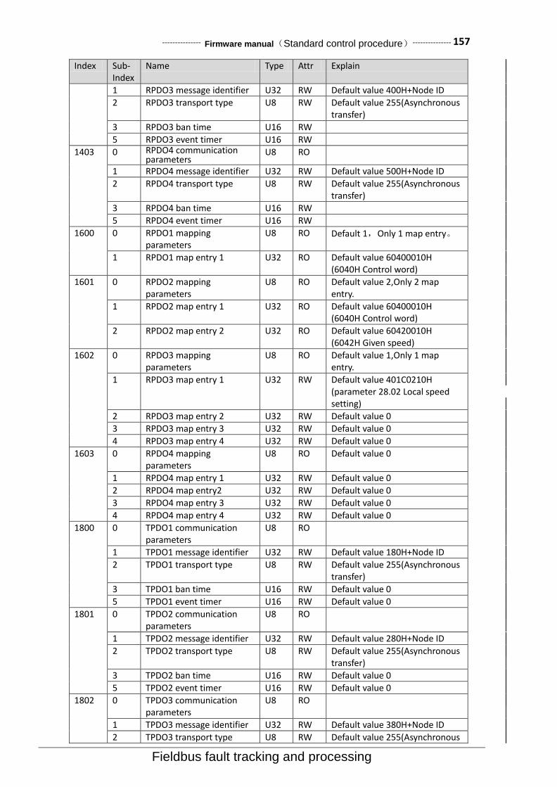
--------------- Firmware manual(Standard control procedure)--------------- 157
Fieldbus fault tracking and processing
Index Sub- Index
Name Type Attr Explain
1 RPDO3 message identifier U32 RW Default value 400H+Node ID
2 RPDO3 transport type U8 RW Default value 255(Asynchronous transfer)
3 RPDO3 ban time U16 RW
5 RPDO3 event timer U16 RW
1403 0 RPDO4 communication parameters
U8 RO
1 RPDO4 message identifier U32 RW Default value 500H+Node ID
2 RPDO4 transport type U8 RW Default value 255(Asynchronous transfer)
3 RPDO4 ban time U16 RW
5 RPDO4 event timer U16 RW
1600 0 RPDO1 mapping parameters
U8 RO Default 1,Only 1 map entry。
1 RPDO1 map entry 1 U32 RO Default value 60400010H (6040H Control word)
1601 0 RPDO2 mapping parameters
U8 RO Default value 2,Only 2 map entry.
1 RPDO2 map entry 1 U32 RO Default value 60400010H (6040H Control word)
2 RPDO2 map entry 2 U32 RO Default value 60420010H (6042H Given speed)
1602 0 RPDO3 mapping parameters
U8 RO Default value 1,Only 1 map entry.
1 RPDO3 map entry 1 U32 RW Default value 401C0210H (parameter 28.02 Local speed setting)
2 RPDO3 map entry 2 U32 RW Default value 0
3 RPDO3 map entry 3 U32 RW Default value 0
4 RPDO3 map entry 4 U32 RW Default value 0
1603 0 RPDO4 mapping parameters
U8 RO Default value 0
1 RPDO4 map entry 1 U32 RW Default value 0
2 RPDO4 map entry2 U32 RW Default value 0
3 RPDO4 map entry 3 U32 RW Default value 0
4 RPDO4 map entry 4 U32 RW Default value 0
1800 0 TPDO1 communication parameters
U8 RO
1 TPDO1 message identifier U32 RW Default value 180H+Node ID
2 TPDO1 transport type U8 RW Default value 255(Asynchronous transfer)
3 TPDO1 ban time U16 RW Default value 0
5 TPDO1 event timer U16 RW Default value 0
1801 0 TPDO2 communication parameters
U8 RO
1 TPDO2 message identifier U32 RW Default value 280H+Node ID
2 TPDO2 transport type U8 RW Default value 255(Asynchronous transfer)
3 TPDO2 ban time U16 RW Default value 0
5 TPDO2 event timer U16 RW Default value 0
1802 0 TPDO3 communication parameters
U8 RO
1 TPDO3 message identifier U32 RW Default value 380H+Node ID
2 TPDO3 transport type U8 RW Default value 255(Asynchronous
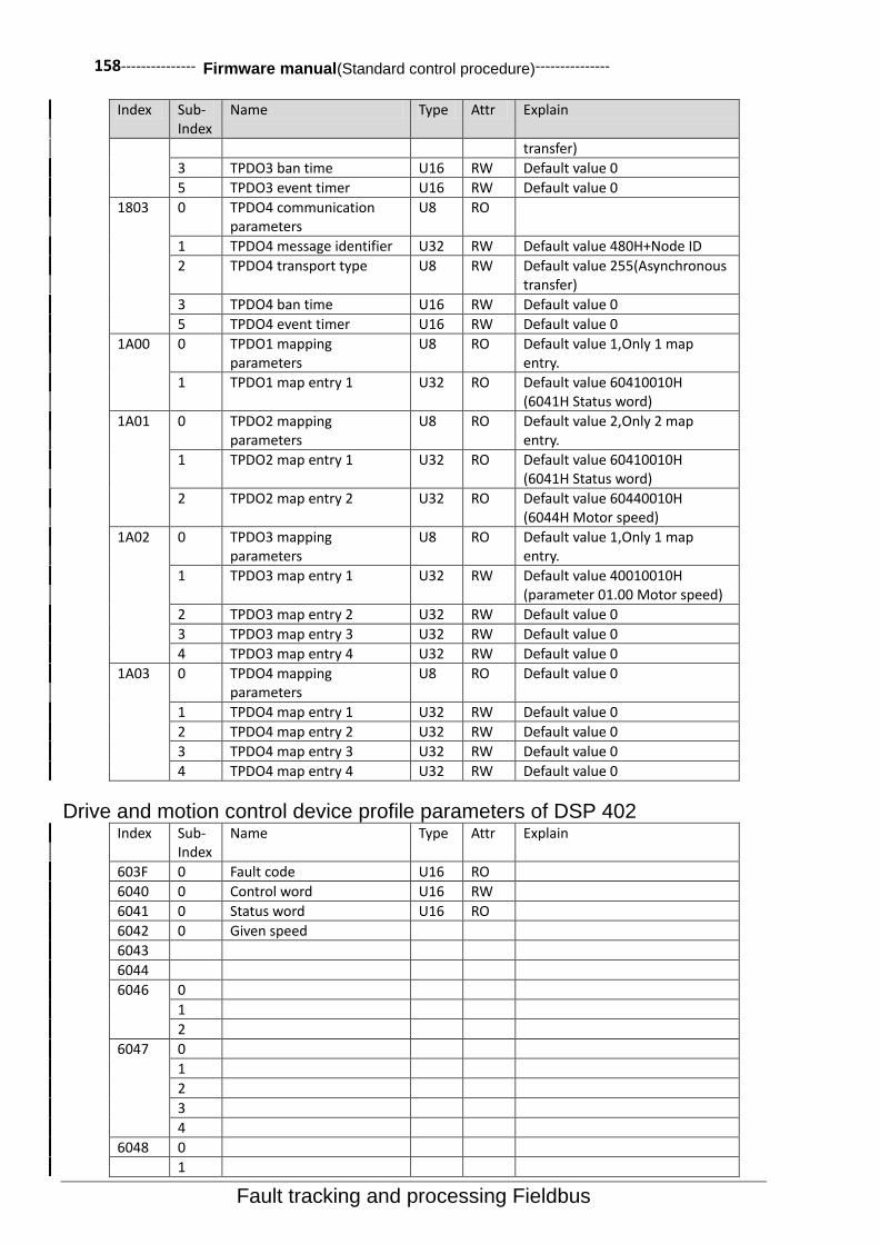
158--------------- Firmware manual(Standard control procedure)---------------
Fault tracking and processing Fieldbus
Index Sub- Index
Name Type Attr Explain
transfer)
3 TPDO3 ban time U16 RW Default value 0
5 TPDO3 event timer U16 RW Default value 0
1803 0 TPDO4 communication parameters
U8 RO
1 TPDO4 message identifier U32 RW Default value 480H+Node ID
2 TPDO4 transport type U8 RW Default value 255(Asynchronous transfer)
3 TPDO4 ban time U16 RW Default value 0
5 TPDO4 event timer U16 RW Default value 0
1A00 0 TPDO1 mapping parameters
U8 RO Default value 1,Only 1 map entry.
1 TPDO1 map entry 1 U32 RO Default value 60410010H (6041H Status word)
1A01 0 TPDO2 mapping parameters
U8 RO Default value 2,Only 2 map entry.
1 TPDO2 map entry 1 U32 RO Default value 60410010H (6041H Status word)
2 TPDO2 map entry 2 U32 RO Default value 60440010H (6044H Motor speed)
1A02 0 TPDO3 mapping parameters
U8 RO Default value 1,Only 1 map entry.
1 TPDO3 map entry 1 U32 RW Default value 40010010H (parameter 01.00 Motor speed)
2 TPDO3 map entry 2 U32 RW Default value 0
3 TPDO3 map entry 3 U32 RW Default value 0
4 TPDO3 map entry 4 U32 RW Default value 0
1A03 0 TPDO4 mapping parameters
U8 RO Default value 0
1 TPDO4 map entry 1 U32 RW Default value 0
2 TPDO4 map entry 2 U32 RW Default value 0
3 TPDO4 map entry 3 U32 RW Default value 0
4 TPDO4 map entry 4 U32 RW Default value 0
Drive and motion control device profile parameters of DSP 402 Index Sub-
Index Name Type Attr Explain
603F 0 Fault code U16 RO
6040 0 Control word U16 RW
6041 0 Status word U16 RO
6042 0 Given speed
6043
6044
6046 0
1
2
6047 0
1
2
3
4
6048 0
1

--------------- Firmware manual(Standard control procedure)--------------- 159
Fieldbus fault tracking and processing
2
6049 0
1
2
604A 0
1
2
60FD 0 Switch input status
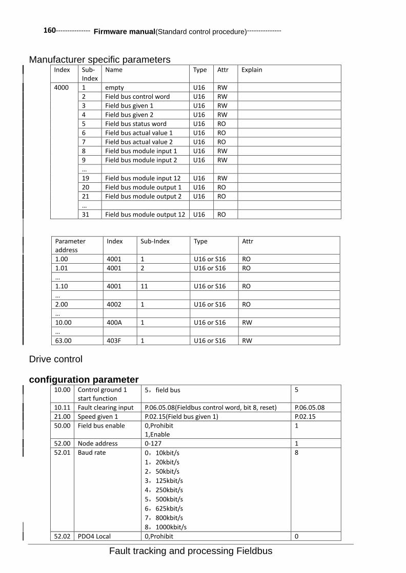
160--------------- Firmware manual(Standard control procedure)---------------
Fault tracking and processing Fieldbus
Manufacturer specific parameters Index Sub-
Index Name Type Attr Explain
4000 1 empty U16 RW
2 Field bus control word U16 RW
3 Field bus given 1 U16 RW
4 Field bus given 2 U16 RW
5 Field bus status word U16 RO
6 Field bus actual value 1 U16 RO
7 Field bus actual value 2 U16 RO
8 Field bus module input 1 U16 RW
9 Field bus module input 2 U16 RW
…
19 Field bus module input 12 U16 RW
20 Field bus module output 1 U16 RO
21 Field bus module output 2 U16 RO
…
31 Field bus module output 12 U16 RO
Parameter address
Index
Sub-Index Type Attr
1.00 4001 1 U16 or S16 RO
1.01 4001 2 U16 or S16 RO
…
1.10 4001 11 U16 or S16 RO
…
2.00 4002 1 U16 or S16 RO
…
10.00 400A 1 U16 or S16 RW
…
63.00 403F 1 U16 or S16 RW
Drive control
configuration parameter 10.00 Control ground 1
start function 5,field bus 5
10.11 Fault clearing input P.06.05.08(Fieldbus control word, bit 8, reset) P.06.05.08
21.00 Speed given 1 P.02.15(Field bus given 1) P.02.15
50.00 Field bus enable 0,Prohibit 1,Enable
1
52.00 Node address 0-127 1
52.01 Baud rate 0,10kbit/s
1,20kbit/s
2,50kbit/s
3,125kbit/s
4,250kbit/s
5,500kbit/s
6,625kbit/s
7,800kbit/s
8,1000kbit/s
8
52.02 PDO4 Local 0,Prohibit 0
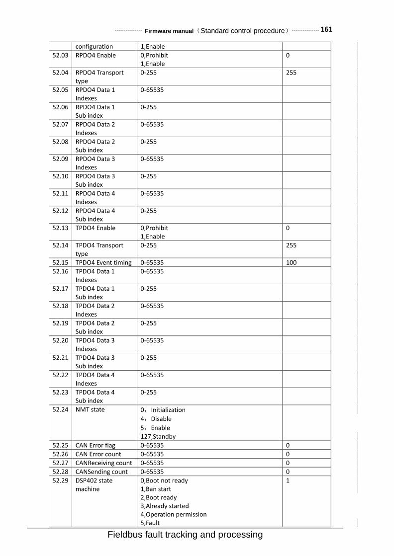
--------------- Firmware manual(Standard control procedure)--------------- 161
Fieldbus fault tracking and processing
configuration 1,Enable
52.03 RPDO4 Enable 0,Prohibit 1,Enable
0
52.04 RPDO4 Transport type
0-255 255
52.05 RPDO4 Data 1 Indexes
0-65535
52.06 RPDO4 Data 1 Sub index
0-255
52.07 RPDO4 Data 2 Indexes
0-65535
52.08 RPDO4 Data 2 Sub index
0-255
52.09 RPDO4 Data 3 Indexes
0-65535
52.10 RPDO4 Data 3 Sub index
0-255
52.11 RPDO4 Data 4 Indexes
0-65535
52.12 RPDO4 Data 4 Sub index
0-255
52.13 TPDO4 Enable 0,Prohibit 1,Enable
0
52.14 TPDO4 Transport type
0-255 255
52.15 TPDO4 Event timing 0-65535 100
52.16 TPDO4 Data 1 Indexes
0-65535
52.17 TPDO4 Data 1 Sub index
0-255
52.18 TPDO4 Data 2 Indexes
0-65535
52.19 TPDO4 Data 2 Sub index
0-255
52.20 TPDO4 Data 3 Indexes
0-65535
52.21 TPDO4 Data 3 Sub index
0-255
52.22 TPDO4 Data 4 Indexes
0-65535
52.23 TPDO4 Data 4 Sub index
0-255
52.24 NMT state 0,Initialization
4,Disable
5,Enable 127,Standby
52.25 CAN Error flag 0-65535 0
52.26 CAN Error count 0-65535 0
52.27 CANReceiving count 0-65535 0
52.28 CANSending count 0-65535 0
52.29 DSP402 state machine
0,Boot not ready 1,Ban start 2,Boot ready 3,Already started 4,Operation permission 5,Fault
1

162--------------- Firmware manual(Standard control procedure)---------------
Fault tracking and processing Fieldbus
52.30 Control word
52.31 Status word
Control word
No. Name Explain 0 Switch On 1:start-up,0:Stop according to the set mode
1 Disable Voltage 1:Keep the current state,0:Free stop .
2 Quick Stop 1:Keep the current state,0:Emergency stop.
3 Enable Operation 1:Allow work,0:Prohibition of work.
4 Ramp Out 0 1:RFG(Ramp function generator)Output force 0
5 Ramp Hold 1:RFG(Ramp function generator)Output hold
6 Ramp In 0 1:RFG(Ramp function generator)Output force 0
7 Reset Fault 0->1:Fault reset
8 Halt 1:Suspend
9 Inching 1 1:Point move command 1
10 Inching 2 1:Point move command 2
11 Remote 1:Remote control
12 Ext2 0:Select external control1, 1:Select external control 2
13-15 Retain
Status word No. Name Explain
0 Ready to Switch On 1:Boot ready
1 Switched On 1:Already started
2 Operation Enabled 1:Have been allowed to work
3 Fault 1:Fault
4 Voltage Disabled 1: Free stop
5 Quick Stop 1:Emergency stop
6 Switch On Disabled 1:Start inhibit
7 Warning 1:Warning
8 Ref Inverted 1:Set to negative
9 Remote 1:Remote control
10 Target Reached 1:Set speed has been reached
11 Internal Limit Active 1:Internal limit
12-15 Retain
Reminder: Other fieldbus communication control such as Profibus-DP Match (set up)the instructions, please refer to the accessories of descriptions or consult relevant technical personnel

--------------- Firmware manual(Standard control procedure)--------------- 163
Fault tracking and processing
7. Fault tracking and processing Contents of this chapter
This chapter lists all of the alarm (warning) and fault information,Including possible causes and corrective actions.Alarm / fault code is displayed on the driver's control keyboard (LED Version display in the form of E-XX).Alarm or fault information is used to indicate that the driver is in an abnormal state.Most alarms and faults can be identified and corrected using the information in this chapter.If you can not rule out the fault,Please contact our representative office.In this chapter,Alarm and fault sort according to the code.
Security
Warning!Only have the qualification of the electrical engineer is allowed to drive conduct for maintenance.Before starting to drive conduct operation,Must read the safety instructions in front of the relevant hardware manual.
How to reset
Can be controlled by pressing the keyboard (RESET key),Or cut off the power supply for a period of
time to reset the fault.After troubleshooting,Motor can start again.
Fault code and interpretation
Code Fault name Possible causes Terms of settlement
01 SC(Output short
circuit)
Output phase to phase short
circuit 、 Or output to earth
short circuit、Or output to the
bus short circuit.
Check whether the motor is short circuit、Check wiring and cable short circuit.Check whether there is a power factor compensation capacitor or surge absorber in the motor cable.
02 OC(Motor over
current)
Motor current exceeds the maximum permissible level of hardware.
Check the motor rated parameters is consistent with the nameplate 、 Check the acceleration and deceleration time is too fast.
03 OV(Bus
overvoltage) Bus voltage exceeds the
maximum permissible level.
Check whether the overpressure stall enable.Check whether the brake resistance is within the recommended range.
04 OH(Drive over heat)
Drive within the radiator
temperature is too high、Or the
internal cavity temperature is too
high、Or module chip
temperature is too high.
Check cooling fan、Ventilation
cooling system is normal 、
Radiator is dust clogging 、Check if the ambient temperature is within the allowable range.
05 GF(Earth leakage) The sum of the output current is not zero,And greater than the allowable value.
Check wiring is loose、Check whether the motor cable leakage.Or the motor output line is too long and there is no additional output reactor.
06 ADC(ADC Fault) Motor current sensor fault 、Analog to digital converter fault or control panel.
Contact local agents or
vendors.
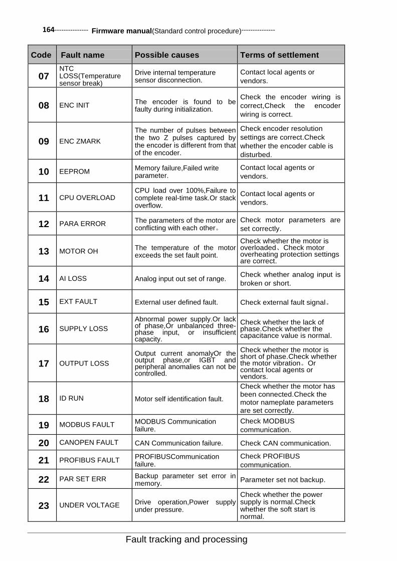
164--------------- Firmware manual(Standard control procedure)---------------
Fault tracking and processing
Code Fault name Possible causes Terms of settlement
07 NTC LOSS(Temperature sensor break)
Drive internal temperature sensor disconnection.
Contact local agents or
vendors.
08 ENC INIT The encoder is found to be faulty during initialization.
Check the encoder wiring is
correct,Check the encoder
wiring is correct.
09 ENC ZMARK
The number of pulses between the two Z pulses captured by the encoder is different from that of the encoder.
Check encoder resolution
settings are correct.Check
whether the encoder cable is
disturbed.
10 EEPROM Memory failure,Failed write parameter.
Contact local agents or
vendors.
11 CPU OVERLOAD CPU load over 100%,Failure to complete real-time task.Or stack overflow.
Contact local agents or
vendors.
12 PARA ERROR The parameters of the motor are conflicting with each other。
Check motor parameters are
set correctly.
13 MOTOR OH The temperature of the motor exceeds the set fault point.
Check whether the motor is overloaded、Check motor overheating protection settings are correct.
14 AI LOSS Analog input out set of range. Check whether analog input is
broken or short.
15 EXT FAULT External user defined fault. Check external fault signal。
16 SUPPLY LOSS
Abnormal power supply.Or lack of phase,Or unbalanced three-phase input, or insufficient capacity.
Check whether the lack of phase.Check whether the capacitance value is normal.
17 OUTPUT LOSS
Output current anomalyOr the output phase,or IGBT and peripheral anomalies can not be controlled.
Check whether the motor is short of phase.Check whether the motor vibration。Or contact local agents or vendors.
18 ID RUN Motor self identification fault.
Check whether the motor has been connected.Check the motor nameplate parameters are set correctly.
19 MODBUS FAULT MODBUS Communication failure.
Check MODBUS
communication.
20 CANOPEN FAULT CAN Communication failure. Check CAN communication.
21 PROFIBUS FAULT PROFIBUSCommunication failure.
Check PROFIBUS
communication.
22 PAR SET ERR Backup parameter set error in memory.
Parameter set not backup.
23 UNDER VOLTAGE Drive operation,Power supply under pressure.
Check whether the power supply is normal.Check whether the soft start is normal.
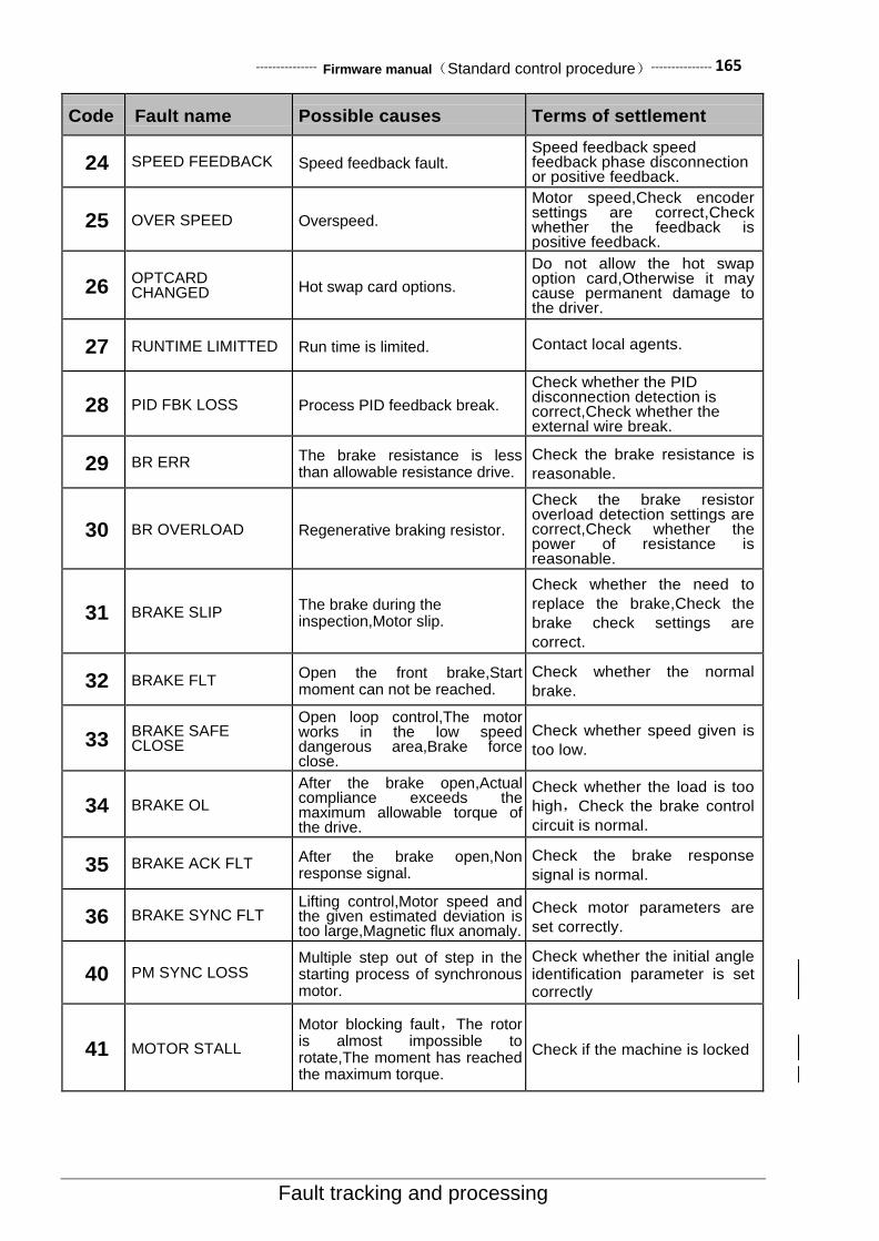
--------------- Firmware manual(Standard control procedure)--------------- 165
Fault tracking and processing
Code Fault name Possible causes Terms of settlement
24 SPEED FEEDBACK Speed feedback fault. Speed feedback speed feedback phase disconnection or positive feedback.
25 OVER SPEED Overspeed.
Motor speed,Check encoder settings are correct,Check whether the feedback is positive feedback.
26 OPTCARD CHANGED Hot swap card options.
Do not allow the hot swap option card,Otherwise it may cause permanent damage to the driver.
27 RUNTIME LIMITTED Run time is limited. Contact local agents.
28 PID FBK LOSS Process PID feedback break.
Check whether the PID disconnection detection is correct,Check whether the external wire break.
29 BR ERR The brake resistance is less than allowable resistance drive.
Check the brake resistance is
reasonable.
30 BR OVERLOAD Regenerative braking resistor.
Check the brake resistor overload detection settings are correct,Check whether the power of resistance is reasonable.
31 BRAKE SLIP The brake during the inspection,Motor slip.
Check whether the need to
replace the brake,Check the
brake check settings are
correct.
32 BRAKE FLT Open the front brake,Start moment can not be reached.
Check whether the normal
brake.
33 BRAKE SAFE CLOSE
Open loop control,The motor works in the low speed dangerous area,Brake force close.
Check whether speed given is
too low.
34 BRAKE OL
After the brake open,Actual compliance exceeds the maximum allowable torque of the drive.
Check whether the load is too
high,Check the brake control
circuit is normal.
35 BRAKE ACK FLT After the brake open,Non response signal.
Check the brake response
signal is normal.
36 BRAKE SYNC FLT Lifting control,Motor speed and the given estimated deviation is too large,Magnetic flux anomaly.
Check motor parameters are
set correctly.
40 PM SYNC LOSS Multiple step out of step in the starting process of synchronous motor.
Check whether the initial angle identification parameter is set correctly
41 MOTOR STALL
Motor blocking fault,The rotor is almost impossible to rotate,The moment has reached the maximum torque.
Check if the machine is locked

166--------------- Firmware manual(Standard control procedure)---------------
More information
8.More information Product and service consulting The user would like to know any more information about this product,Can contact with our local representative
office,Please provide the serial number of the product and the serial number of the product to be consulted.
Provide feedback about this manual Welcome you to our manual put forward valuable suggestions,Contact with our local representative office,Or
call our customer service phone directly.

Shenzhen Cumark New Technology Co., Ltd. Address: Hongfa Industrial Park, Tangtou Community, Shiyan Town, Bao'an District, Shenzhen Postal code: 518108 Tel.:0755-81785111 Fax.:0755-81785108 Hotline.: (+86) 400 619 2001 Website: www.cumark.com.cn
Data
codin
g :
36
01
00
04
Chin
ese v
ers
ion f
irm
ware
ma
nua
l 【
Sta
nda
rd c
ontr
ol p
roce
du
re 】
Editio
n :
V1.4【
SW
1.6
0】
effective d
ate
:2017
-04-1
3