Embed Size (px)
Citation preview

FRISCC: Fire resistance of innovative and slender concrete filled tubular composite columns RFSR-CT_2012_00025
1
Research Programme of the Research Fund for Coal and Steel
Steel RTD
Project carried out with a financial grant of the Research Programme of the Research Fund for Coal and Steel
Mid-term Report
Technical Report No: 2 Issued on 27/03/2014
Period of Reference: 01/07/2012 – 31/12/2013
Technical Group: TGS8 “Steel products and applications for buildings, construction and industry”
“Fire resistance of innovative and slender concrete filled tubular composite columns”
Project Acronym FRISCC
Grant Agreement Number: RFSR-CT_2012_00025
Beneficiaries:
Universitat Politècnica de València, Spain UPVLC
Centre Technique Industriel de la Construction Métallique, France CTICM Gottfried Wilhelm Leibniz Universitaet Hannover, Germany LUH Imperial College of Science, Technology and Medicine, London, UK IMPERIAL Universidade de Coimbra, Portugal UC Asociación de investigación de las industrias de la Construcción, Spain AIDICO Conducciones y Derivados, S.A., Spain CONDESA
Coordinator: Manuel L. Romero Universitat Politècnica de València

FRISCC: Fire resistance of innovative and slender concrete filled tubular composite columns RFSR-CT_2012_00025
2
Authors: Manuel L. Romero (UPVLC) Ana Espinós (UPVLC) Cristophe Renaud (CTICM) Gisèle Bihina (CTICM) Peter Schaumann (LUH) Inka Kleiboemer (LUH) Leroy Gardner (IMPERIAL) Cheng Fang (IMPERIAL)
Finian McCann (IMPERIAL) Joao Paulo Rodrigues (UC)
Luis Laim (UC) Carlos Lozano (AIDICO) Gorka Iglesias (CONDESA)
Commencement Date: 01/07/2012
Completion Date: 30/06/2015

FRISCC: Fire resistance of innovative and slender concrete filled tubular composite columns RFSR-CT_2012_00025
3
Distribution List
Chairman Mr Louis-Guy CAJOT ARCELOR PROFIL ARCELORMITTAL BELVAL & DIFFERDANGE S.A. LU-4009 ESCH-SUR-ALZETTE e-mail: [email protected] LUXEMBOURG
Members Ms Nancy BADDOO SCI THE STEEL CONSTRUCTION INSTITUTE LBG GB- ASCOT (BERKSHIRE) SL5 7QN Buckhurst Road, Silwood Park e-mail: [email protected] Organisation: Direct fax: UNITED KINGDOM Prof. Antonio Augusto FERNANDES Faculdade de Engenharia Mecânica UNIV PORTO UNIVERSIDADE DO PORTO PT-4099-002 PORTO e-mail: [email protected] PORTUGAL Mr Anthony KARAMANOS A.S. KARAMANOS A.S. KARAMANOS & ASSOCIATES Paleo Faliro GR-175 62 ATHENS 122, Sirinon street e-mail: [email protected] HELLAS Prof. Andrzej KLIMPEL SUT SILESIAN UNIVERSITY OF TECHNOLOGY - POLITECHNIKA SLASKA PL-44 100 GLIWICE e-mail: [email protected] POLAND Mr Jouko KOUHI FCSA FINNISH CONSTRUCTIONAL STEELWORK ASSOCIATION e-mail: [email protected] FINLAND

FRISCC: Fire resistance of innovative and slender concrete filled tubular composite columns RFSR-CT_2012_00025
4
Prof. Dr.-Ing. Ulrike KUHLMANN UNIV STUTTGART Institute of Structural Design Pfaffenwaldring, 32 DE-70569 STUTTGART u.kuhlmann@e-mail: ke.uni-stuttgart.de GERMANY Prof. Joaquín ORDIERES MERE Ingeniería de organización, Admin. Empresas UPM UNIVERSIDAD POLITÉCNICA DE MADRID e-mail: [email protected] ESPAÑA Dr. Walter SALVATORE UNIV PISA UNIVERSITA DI PISA - DIPARTAMENTO INGEGNERIA CIVILE e-mail: [email protected] ITALIA Dr. Bin ZHAO CTICM CENTRE TECHNIQUE INDUSTRIEL DE LA CONSTRUCTION METALLIQUE Direction Recherche et Valorisation Espace technologique l'Orme des Merisiers Immeuble Apollo FR-91193 SAINT-AUBIN FRANCE Mr Adam BANNISTER TATA STEEL UK TATA STEEL UK LIMITED - SWINDEN e-mail: [email protected] UNITED KINGDOM Dr.-Ing. Giuseppe DEMOFONTI CSM CENTRO SVILUPPO MATERIALI SPA e-mail: [email protected] ITALIA Dr. Gerhard KNAUF SZMF SALZGITTER MANNESMANN FORSCHUNG GmbH e-mail: [email protected] DEUTSCHLAND

FRISCC: Fire resistance of innovative and slender concrete filled tubular composite columns RFSR-CT_2012_00025
5
Table of Contents
Abstract 6
Acronyms 7
Notation 8
I. Mid-term summary 9
I.1. Part 1. Management and coordination aspects 9
1.1.- Project overview 9
1.2.- Bar chart comparing actual situation with initial planning 11
1.3.- List of deliverables 14
1.4.- Progress made and problems encountered 15
I.2. Part 2. Scientific and technical progress 18
2.1.- Specific project objectives for the reporting period 18
2.2.- Results obtained 18
2.2.1.- WP1: Evaluation of the existing design methods 18
2.2.2.- WP2: Experimental tests 26
2.2.3.- WP3: Numerical simulations 64
2.2.4.- WP4: Simplified design methods 91
2.2.5.- WP5: Design tools, dissemination and code additions 93
2.2.6.- WP6: Coordination 98
2.3.- Preliminary conclusions 99
2.4.- Publications and patents 100
II. Copy of the signed Technical Annex 105

FRISCC: Fire resistance of innovative and slender concrete filled tubular composite columns RFSR-CT_2012_00025
6
Abstract
Concrete-filled steel tubular (CFST) members are commonly used as composite columns in modern buildings. However, current guidelines for member design in fire (EN1994-1-2) have been proved to be unsafe once the relative slenderness is higher than 0.5. In addition, the simplified design methods of Eurocode 4 are limited to circular or square CFST columns, while in practice columns with rectangular and elliptical hollow sections are being increasingly used because of their architectural aesthetics. The proposed development of new design tools will be based on numerical and experimental work and should be incorporated in Eurocodes for broader dissemination.
This report describes the technical activities carried out under this RFCS project RFSR CT-2012-00025 during period 1 July 2012 to 31 December 2013. This is the second annual report of the project. The work during this period has involved:
- Review of the existing usage. - Review of the results of previous tests. - Definition of test parameters. - Evaluation of the existing design methods. - Design of test specimens and corresponding setup. - Tests on the material properties - Fire tests on slender concrete-filled CHS and SHS columns. - Fire tests on slender concrete-filled RHS and EHS columns. - Room temperature tests on concrete-filled EHS columns. - Numerical simulations - Development of user friendly design tool

FRISCC: Fire resistance of innovative and slender concrete filled tubular composite columns RFSR-CT_2012_00025
7
Acronyms
CFCHS Concrete filled circular hollow section
CFEHS Concrete filled elliptical hollow section
CFRHS Concrete filled rectangular hollow section
CFSHS Concrete filled square hollow section
CFST Concrete filled steel tube
CFSTES Concrete filled steel tube with embedded steel core
CHS Circular hollow section
EC1 Eurocode 1
EC2 Eurocode 2
EC3 Eurocode 3
EC4 Eurocode 4
EHS Elliptical hollow section
FEA Finite element analysis
FEM Finite element modelling
F-F Fixed-fixed supporting conditions
FRR Fire resistance rating
HSC High strength concrete
NSC Normal strength concrete
P-P Pinned-pinned supporting conditions
RHS Rectangular hollow section
SHS Square hollow section

FRISCC: Fire resistance of innovative and slender concrete filled tubular composite columns RFSR-CT_2012_00025
8
Notation
Latin lower case letters
e: load eccentricity
fc: compressive strength of concrete
fs: yield strength of reinforcing steel
fy: yield strength of structural steel
kRA: axial restraint
t: thickness of the steel tube
Greek lower case letters
y: relative slenderness of the column at room temperature, for major axis buckling
z: relative slenderness of the column at room temperature, for minor axis buckling
: percentage of reinforcement
: diameter of the rebars
μ: load level
Roman upper case letters
B: width of a square section / smaller outer dimension of a rectangular/elliptical section
B.C.: Boundary conditions
D: outside diameter of a circular section
F-F = fixed-fixed boundary conditions
H: larger outer dimension of a rectangular/elliptical section
L: length of the column
N: load value
P-P = pinned-pinned boundary conditions
R: fire resistance duration

FRISCC: Fire resistance of innovative and slender concrete filled tubular composite columns RFSR-CT_2012_00025
9
I. Mid-term summary
I.1. Part 1. Management and coordination aspects
1.1.- Project Overview
CATEGORY OF RESEARCH: STEEL
TECHNICAL GROUP: TGS8
REFERENCE PERIOD: 01/07/2012 – 31/12/2013
GRANT AGREEMENT N°: RFSR-CT_2012_00025
TITLE: Fire resistance of innovative and slender
concrete filled tubular composite columns
BENEFICIARIES:
UNIV. POLITÈCNICA DE VALÈNCIA (UPVLA) CTICM
LEIBNIZ UNIVERSITAET HANNOVER (UHANN)
IMPERIAL COLLEGE LONDON (ICST) UNIVERSIDADE DE COIMBRA (UC)
AIDICO CONDESA
COMMENCEMENT DATE: 01/07/2012
COMPLETION DATE: 30/06/2015
WORK UNDERTAKEN: Refers to Section 2.2
MAIN RESULTS: Refers to Section 2.2
FUTURE WORK TO BE UNDERTAKEN: Refers to Section 2.2
ON SCHEDULE : YES
The WP2 has been moved forward
PROBLEMS ENCOUNTERED: Refers to Section 1.4
CORRECTION – ACTIONS
(USE OF A TABLE IS RECOMMENDED): None
PUBLICATIONS – PATENTS Refers to Section 2.4

FRISCC: Fire resistance of innovative and slender concrete filled tubular composite columns RFSR-CT_2012_00025
10
For Mid-Term and Final reports only:
BUDGET INFORMATION PER BENEFICIARY Based on overall costs (independently from EU financial contribution)
BENEFICIARY (incl. coordinator)
Total amount spent to date (€)
Total allowable cost (€) as foreseen in Grant Agreement
UPVA 105.328,22 208.498
CTICM 64.880,04 222.812
UHANN 119.457,36 343.075
ICST 147.195,96 356.039
UC 94.922,15 317.685
AIDICO 88.086,23 171.263
CONDESA 34.371,22 40.241

FRISCC: Fire resistance of innovative and slender concrete filled tubular composite columns RFSR-CT_2012_00025
11
1.2.- Bar chart comparing actual situation with initial planning
II CORRECTED PROGRAMME BAR CHART (TASK, PARTNER, DELIVERABLES, MILESTONES )
Please use dark colours to maximise readability upon photocopying
Work package
Work package title Deliverables Hours on project/ Beneficiary 1st year 2nd year 3rd year
1 2 3 4 5 6 7 I II III IV I II III IV I II III IV
WP 1 Evaluation of the existing design methods
400 300 300 150 200 200 600
Task 1.1 Review of the existing usage
Technical Document
100 100 100 0 0 0 300
Task 1.2 Review of the results of previous tests
Report 100 100 100 75 100 100 0
Task 1.3 Definition of test parameters
Report 100 0 100 75 100 100 0
Task 1.4 Evaluation of the existing design methods
Report 100 100 0 0 0 0 300
WP 2 Experimental Tests 2300 0 1200 2650 4560 4240 0
Task 2.1 Design of test specimens and corresponding setup
Technical Document
200 0 200 150 200 300 0 Advanced
Work
Task 2.2 Material Properties Report 0 0 0 750 800 0 0
Task 2.3 Tests (fire) on slender concrete-filled CHS and SHS
Report 700 0 0 0 1780 1310 0
FRISCC: Fire resistance of innovative and slender concrete filled tubular composite columns RFSR-CT_2012_00025
12
Task 2.4 Tests (room and fire) on slender concrete-filled RHS and EHS
Report 1400 0 0 1750 1780 2630 0
Task 2.5 Tests (room and fire) on concrete-filled CHSES
Report 0 0 1000 0 0 0 0
WP 3 Numerical Simulations (numerical validation and parametric studies)
1100 900 4000 1373 2000 0 0
Task 3.1 Tests on slender concrete-filled CHS and SHS
Report 400 0 0 0 1000 0 0
Task 3.2 Tests on slender concrete-filled RHS and EHS
Report 700 0 0 1373 1000 0 0
Task 3.3 Tests on concrete-filled CHSES
Report 0 900 4000 0 0 0 0
WP 4 Simplified design methods
800 1500 800 2500 0 0 0
Task 4.1 Extension of simplified methods for CHS and SHS for slender members
Technical Document
400 600 0 0 0 0 0
Task 4.2 Development of simplified methods for RHS and EHS for full slenderness range
Research Report
300 600 0 2000 0 0 0

FRISCC: Fire resistance of innovative and slender concrete filled tubular composite columns RFSR-CT_2012_00025
13
Task 4.3 Development of simplified methods for CHSES
Research
Report
0 200 800 0 0 0 0
Task 4.4 New design recommendations for Eurocode 4
Technical Document
100 100 0 500 0 0 0
WP 5 Design Tools, Dissemination and Code additions
200 1200 600 35 0 0 200
Task 5.1 Workshop Workshop 0 0 0 35 0 0 100
Task 5.2 Development of user friendly design tool
Software 0 900 0 0 0 0 100
Task 5.3 Proposal for code additions
Technical Document
200 300 600 0 0 0 0
WP 6 Coordination Project reports, mid-term report
and final report
1000 0 0 0 0 0 0
Total Hours on project 5800 3900 6900 6708 6760 4440 800
Nomenclature:
CHS = Circular Hollow Section
SHS = Square Hollow Section
RHS = Rectangular Hollow Section
EHS = Elliptical Hollow Section
CHSES = Circular Hollow Section with embedded Steel Core

FRISCC: Fire resistance of innovative and slender concrete filled tubular composite columns RFSR-CT_2012_00025
14
1.3.- List of deliverables
Deliverable Form Partners Due date Status Location
1.1
Technical document describing the practical application of
slender CFST columns and the actual use of the innovative
types of composite sections worldwide
CTICM Y1Q2 (Dec'12) submitted CIRCABC
1.2Reports summarizing the results from all the tests existing in
the literature and from previous research projects
UPV, CTICM,
LUH, UC, ICY1Q3 (March'13) submitted CIRCABC
1.3 Technical report defining in detail the test parameters UPV Y1Q4 (June'13) submitted CIRCABC
1.4Research report simulating the previous parameters in the
different methods of each design code UPV Y1Q4 (June'13) submitted CIRCABC
2.1Technical document describing in detail the setup of the tests
and the dimensions of the specimens
UPV, LUH, UC,
ICY1Q4 (June'13) submitted CIRCABC
2.2 Full test reports including detailed experimental dataUPV, LUH, UC,
IC, AIDICOY3Q1 (Sept'14) in process -
3Document with comparisons between the experimental tests
and the numerical simulations
UPV, LUH, IC,
UCY3Q2 (Dec'14) in process -
4Technical document describing a simple design method for
predicting the fire resistance of slender CFT columnsUPV, CTICM Y3Q3 (March'15) pending -
5.1 Organization of a workshop to disseminate the results IC, CONDESA Y3Q4 (June'15) pending -
5.2 User-friendly software CTICM Y3Q3 (March'15) pending -
5.3 Amendment in the future revision of EC4 Part 1.2 CTICM Y3Q4 (June'15) pending -

FRISCC: Fire resistance of innovative and slender concrete filled tubular composite columns RFSR-CT_2012_00025
15
1.4.- Progress and problems encountered
1.4.1.- Progress
At the moment, the course of the project is in good progress, following the schedule established in the programme bar chart, with some of the tasks being advanced with respect to the initial schedule. During this reporting period, comprising the first 18 months of the project, the following tasks have been carried out:
Work package 1
All the tasks within this work package have been finished and the corresponding deliverables (1.1, 1.2, 1.3 and 1.4) submitted.
Work package 2
Task 2.1 has been finished and the deliverable (2.1) submitted, consisting of the design of the test specimens and corresponding setup. Tasks 2.2 to 2.5 are currently in course, where the different partners are carrying out their corresponding tests.
In particular, UPVLC-AIDICO are conducting the fire tests on isolated columns, UC is testing columns in sub-frames, LUH is preparing the fire tests on concrete-filled CHS with embedded steel core profile and IMPERIAL has recently started the room temperature tests on concrete-filled EHS columns. A summary of the number of tests already performed by each partner is given next:
Partner Number of tests carried out Total number of tests to perform
UC 6 24 UPVLC + AIDICO 26 36
IMPERIAL 1 18 LUH* 0 22
* Task 2.5 started in July 2013. The test specimens are currently being prepared for testing.
Work package 3
The development and validation of the numerical models from the different partners is being carried out. Initial numerical models have been developed for representing the different types of situations to study: isolated columns subjected to fire, columns in sub-frames subjected to fire, concrete-filled CHS with embedded steel core profile and concrete-filled EHS columns at room temperature.
The parameters of these preliminary numerical models have been initially calibrated by comparison with test results available in the literature.
At the moment, the numerical models are being validated against the test results obtained in WP-2, work which is being carried out in parallel to the development of the experimental tests.
Work package 4
A review on the methods available in the literature and the different building codes for evaluating the fire resistance of concrete-filled tubular columns has been carried out.
The partners involved in this work package are already working in the development of new simplified design methods which solve the current limitations of Eurocode 4. These methods need to be extended and completed by means of the experimental and numerical results obtained in WP-2 and WP-3 within this project, which will be done during the course of this work package.

FRISCC: Fire resistance of innovative and slender concrete filled tubular composite columns RFSR-CT_2012_00025
16
Work package 5
The development of the user friendly design tool has started. A preliminary design of the interface of this design tool has been done based on an existing calculation software by CTICM. As soon as the results from WP-4 are ready, the developed simplified design methods will be implemented in this software.
Work package 6
Three meetings have taken place in this reporting period, which have been held in Paris (CTICM), Hannover (LUH) and Valencia (UPVLC).
A workshop on the finite element modelling of innovative concrete-filled tubular columns under room and elevated temperatures was celebrated in LUH on the occasion of the second meeting, where all the partners involved in WP-2 (numerical simulations) participated.
A website has been developed for use by the project’s partners to enable quick and efficient communications throughout the project. Documents and information such as minutes of meetings, contact details and technical reports are being posted on the website.
1.4.2.- Problems encountered
Work package 1
In task 1.1, no examples of the current usage of concrete-filled elliptical columns can be provided, since these tubular shapes have not yet been used filled with concrete in any real building. This is due to the lack of design guidance of these relatively new types of sections, which have not been included yet in Eurocode 4. Given the lack of data on CFEHS columns, the review of this part has been focused on unfilled EHS columns. The same problem was encountered for RHS columns, for which a limited number of practical applications have been found.
In task 1.2, while a great number of fire tests have been conducted on circular and square CFST columns, no cases were found in the literature of fire tests with EHS columns filled with concrete and a very limited number of fire tests were found on RHS columns.
In task 1.4, a similar problem was encountered when trying to evaluate the existing design methods, as most of them are limited to circular and square sections. No methods exist so far in the design codes for the fire evaluation of CFST columns of elliptical and rectangular shape, nor for CFST columns with embedded steel core profile. Given this limitation, an initial evaluation of the current methods for CHS and SHS columns has been carried out, while the study of the calculation methods for EHS and RHS columns and CFST columns with embedded steel core profile will be done in work package 4, where the proposals of the different partners of this project will be studied in depth and improved on the basis of the experimental and numerical results obtained from this project.
Work package 2
At the stage of the design of the different tests to perform, some difficulties were encountered, such as limitations of space in the furnace for the application of large eccentricities, test load too high for the hydraulic jack capacity, etc.
Some problems were also experienced with the availability of the initially planned sections, mainly for the elliptical and rectangular tubes, all of which has led the different partners of the project to agree a series of modifications to be made over the initial list of tests.

FRISCC: Fire resistance of innovative and slender concrete filled tubular composite columns RFSR-CT_2012_00025
17
Work package 3
For task 3.3, it was written in the Technical Annex B4 that CTICM would perform numerical simulations of columns in sub-frames with embedded steel core profile, when it should be written “isolated columns”.
It is clarified that within this work package, CTICM will simulate all types of cross-sections (CHS, SHS, RHS and EHS) apart from columns with embedded steel core profile. CTICM will compare their numerical results with all the experimental tests carried out by the rest of the partners.
Work package 4
No problems were encountered.
Work package 5
No problems were encountered.
Work package 6
No problems were encountered.
1.4.3.- Corrective actions
The lists of tests to perform in tasks 2.3 and 2.4 have been redefined on the basis of the difficulties encountered at the test setup stage (maximum capacities and limited dimensions of the testing equipment) and in accordance with the limitations in the market availability regarding the elliptical and rectangular sections.
In task 2.3, it was decided that two of the circular columns (C3 and C4) and their square counterparts (S3 and S4) were tested under concentric axial load, in order to have a reference for comparison of the effect of the load eccentricity.
For the fire tests, the axial load level has been selected to allow for at least 30 minutes fire resistance, as if the applied load is too severe only short fire resistance times are obtained. Thus, in the fire tests on columns with large eccentricities the load level has been fixed to a 20%, while for the tests on columns in sub-frames a 30% load level will be applied.
Due to cost reasons, the large-scale column fire test to be carried out by LUH (embedded steel column) will be performed at BAM Berlin instead of MPA Braunschweig, as it was mentioned in the Technical Annex B4.

FRISCC: Fire resistance of innovative and slender concrete filled tubular composite columns RFSR-CT_2012_00025
18
I.2. Part 2. Scientific and technical progress
2.1.- Specific project objectives for the reporting period
For this reporting period, comprising the first 18 months of the project, the following specific objectives must be accomplished:
- Work package 1: Evaluation of the existing design methods. This work package must be finished and the corresponding deliverables (1.1, 1.2 ,1.3 and 1.4) submitted.
- Work package 2: Experimental tests. From this work package, task 2.1 must be finished, with the design of the test specimens and corresponding setup completed by all the partners. Tasks 2.2 to 2.5, consisting on the different tests to be carried out within this work package, must be in course.
- Work package 3: Numerical simulations. The development and validation of the numerical models from the different partners must be started.
- Work package 5: Design tools, dissemination and code additions. The development of a user friendly design tool must be started.
These specific objectives have been accomplished during the first 18 months, and their results are reported in the following sections on a task per task basis.
2.2.- Results obtained
2.2.1.- WP1: Evaluation of the existing design methods
Task 1.1: Review of the existing usage
A technical report describing practical applications of slender CFST columns and the current use of innovative types of composite sections was submitted together with the first six-month report, corresponding to Deliverable 1.1 in this project. The main results obtained in this task are summarized next.
Due to their aesthetical aspect and the significant fire resistance they can provide, CFT columns are mainly used in high-rise buildings and bridges. Illustration of their use can also be found in industrial buildings, electricity transmitting poles, subways, open car parks, office or residential buildings, namely in Western countries (mainly UK, Northern America and France) and Asia (Japan).
Traditionally, CFT columns are made of circular, square or rectangular steel tubes filled with plain or reinforced concrete. In case of plain concrete infill, external fire protection is often required, as observed in Mitsui Soko Hakozaki (Japan) and Montevetro (UK) apartment blocks. In case of reinforced concrete, steel bars are utilized, e.g. Riverside (Australia), and Praetorium (France) office buildings, St. Thomas Elementary School (Canada) and Peckham Library (UK), or replaced by metal fibres, e.g. Rochdale bus station (UK). Reinforced concrete columns can meet up to 120-minute standard fire resistance without any fire protection.
Innovative solutions include tube-in-tube systems, fully encased inner H-profiles and elliptical steel tubes (see Fig. 1 and Fig. 2). In case of tube-in-tube columns, the inner steel core can be either hollow, e.g. Queensberry House (UK), or solid, e.g. Highlight Towers (Germany). Regarding elliptical sections, with different major and minor axis properties, an example can be found in Neo Bankside bracing members (UK). However, owing to the lack of standard design methods, this shape is scarcely used.
Regarding beam-to-column connections, European design codes recommend using bearing blocks combined to additional studs, or shear flats welded to both steel walls for composite

FRISCC: Fire resistance of innovative and slender concrete filled tubular composite columns RFSR-CT_2012_00025
19
beams. Besides, according to CIDECT research, reverse channel joints represent an economical solution in case of I-beams (see Fig. 3).
When compared to steel solutions, CFT columns can generate significant savings as they usually do not require any fire protection. Different simple design methods are proposed in the fire part of Eurocode 4, among which Annex H model that has proved to be unconservative for slender columns, and the French National Annex model that can only be applied to square and circular sections without any inner steel core. As a consequence, further investigation for innovative solutions is needed to develop a simple design method with a wider scope of application.
CONCRETE CORE
STEEL TUBE
CFCHS CFSHS
CFEHS CFRHS
Fig. 1. Different types of CFT sections [20].
CHS: circular hollow section, SHS: square hollow section,
EHS: elliptical hollow section, RHS: rectangular hollow section
Fig. 2. CFT columns with an inner steel core: Millennium Tower (Wien, Austria).

FRISCC: Fire resistance of innovative and slender concrete filled tubular composite columns RFSR-CT_2012_00025
20
Fig. 3. Reverse channel joint.
Task 1.2: Review of the results of previous tests
A review of the test results available in the literature on CFST columns subjected to fire has been carried out. With all the documentation reviewed in this task, a database has been created, which has allowed to know which range of values of the parameters have already been experimentally studied and to have a basis to decide the values to test in the experimental program of this project.
A technical report describing the more relevant characteristics of the different fire testing programs found in the literature is presented in Deliverable 1.2. The main results obtained in this task are summarized next.
In order to follow the usual procedure to develop a simple design model, three steps are required:
- Experimental investigation on the basis of small or large scale tests;
- Advanced calculations on the basis of finite difference or finite element modelling;
- Simple design method implying a comparison to the numerical model.
In a cost-effective purpose, a review of existing test results enables to conduct only tests that have not been carried out yet, and to enlarge the amount of available results once the first step is completed. Therefore, a list of available tests on CFT columns exposed to a standard fire was provided.
These tests were conducted from the 1970’s to the 2010’s in such countries as Canada, the UK, France, Germany, China and Spain. The specimens were made of square or circular sections filled with plain or reinforced concrete and an overall length from 3.18 m (Spanish tests) to 5.8 m (German tests). The concrete core could be made of siliceous or calcareous

FRISCC: Fire resistance of innovative and slender concrete filled tubular composite columns RFSR-CT_2012_00025
21
aggregate, and reinforced with steel bars or fibres. In some of the French tests, the tube was made of stainless steel.
The columns were exposed to the ASTM fire curve (Canadian tests only) or the ISO fire curve. A constant axial load was applied at the top of the column, and concentric in most cases, but could also be eccentric. Different support conditions were considered:
- The column ends were both pinned; - The column ends were both fixed; - The column was fixed at its bottom end and pinned at its top end.
The temperatures of surrounding hot gases and in the composite cross-sections at different locations along the columns, as well as the axial displacement at the top of the columns were also recorded all through the fire test duration until failure which was generated by buckling or compression.
A look at a time – axial displacement curve (see Fig. 5) highlights different steps in the column behaviour:
- An elongation of the column due to thermal expansion of the column until reaching a peak value; this thermal expansion generates differential axial displacements between the steel tube and the concrete core due to different material properties;
- A shortening of the column due to the reduction of the steel tube mechanical properties; the load bearing-capacity of the column is then taken over by the concrete core until failure.
Besides, a look at the time – temperature curves in a given cross-section can put into evidence a non-symmetric temperature field. In Fig. 4, given d the inner diameter of the steel tube, TC5 provides temperatures at d/4 from the centre of the cross-section, whereas TC2 and TC3 provide temperatures at d/3 and d/6. Hence, in case of symmetric cross-sectional temperature field, TC5 should provide lower temperatures than TC2 and greater temperatures than TC3, which is not observed in the graph. If thermocouples were properly set, such an asymmetric temperature distribution can lead to a load eccentricity, modifying the assumed behaviour of the column and reducing its expected buckling resistance.
The results from these tests have also highlighted the difficulty to control other set-up parameters. For instance, considering an unreinforced column prepared by the very same laboratory and tested in different facilities under a concentric load, a significant discrepancy can be observed in terms of fire resistance. In the example given in Table 1, the five specimens were all prepared at C.S.T.B. testing facility and had the same material properties, and the furnace temperature was quite homogenous. As a consequence, this discrepancy is probably caused by support and/or loading conditions which can differ from one laboratory to another. These conditions are supposed to be constant all through the test, which might not be verified when looking at the actual time – load curve. In addition, the rotational freedom of the supports can induce secondary bending moments, once again modifying the expected buckling resistance of a column.
Therefore, even though these tests results have provided essential data to calibrate numerical models used to develop the existing design methods, they should be accounted for very cautiously.

FRISCC: Fire resistance of innovative and slender concrete filled tubular composite columns RFSR-CT_2012_00025
22
Table 1. Comparison of the fire resistance of a column tested by different laboratories [8]
Country Laboratory
Depth of the cross-section (mm)
Thickness of the
steel tube (mm)
Compressive strength of concrete (N/mm2)
Yield strength
of structural
steel (N/mm2)
Axial load (kN)
Load ratio (%)
Fire resistance
(min)
Germany I.B.M.B.
260 6.3 37 415 800 18
81
France UTI/CTICM 86
France C.S.T.B. 98
UK F.I.R.T.O. 133
Germany B.A.M. 134
Fig. 4. Cross-sectional temperature distribution vs. time (Canadian test)

FRISCC: Fire resistance of innovative and slender concrete filled tubular composite columns RFSR-CT_2012_00025
23
Fig. 5. Axial displacement vs. time (Canadian test)
Task 1.3: Definition of test parameters
From the analysis of the results of previous tests, carried out in Task 1.2, the exact parameters which will be varied during experimental tests of this project have been decided.
The parameters which will be analysed in the experimental tests, together with their range of variation, are given in Deliverable 1.3. The main results obtained in this task are summarized next.
The range of variation of the different parameters of the experimental tests on unrestrained concrete-filled columns to be carried out by UPVLC-AIDICO is given in Table 1.

FRISCC: Fire resistance of innovative and slender concrete filled tubular composite columns RFSR-CT_2012_00025
24
Table 1. Tests on unrestrained concrete-filled CHS, SHS, EHS and RHS columns subjected to fire (UPVLC-AIDICO)
Variable Specified values
L (m) 3180
fy (MPa) 355
fs (MPa) 500
fc (MPa) 30
(%) 20
Geometry CHS SHS EHS RHS
End conditions P-P P-P P-P / P-F P-P
Cross-section size
193.7x8, 273x10 150x8, 220x10 220x110x12,
320x160x12.5 250x150x10, 350x150x10
D0/t* 24.21 – 27.3 23.87 – 28.01 14.13 – 19.74 25.46 – 31.83
A/V 14.65 – 20.65 18.18 – 26.67 19.27 – 28.04 19.05 – 21.33
y**
0.50 – 0.72 0.55 – 0.80 0.44 – 0.46 0.31 – 0.48
z** 0.79 – 0.84 0.71 – 0.74
ey (mm)
0 – 0.75D (0 – 145.27)
0 – 0.75B (0 – 112.5)
0 – 0.5×(2a) (0 – 160)
0 – 0.5H (0 – 175)
ez (mm) 0 – 0.5×(2b)
(0 – 80) 0 – 0.5B (0 – 75)
(%) 2.4 – 5 2.52 – 5.15 0 – 2.57 0 – 2.69
In this table, D0 is defined as the diameter of that circular section which has the same
perimeter as the square/elliptical/rectangular section (D0 = P/π), while y and
z are the
relative slenderness for major axis buckling and minor axis buckling, respectively.
The parameters to be tested by Universidade de Coimbra and their range of variation are the same as those used by UPV, with an additional parameter of the axial restraint, which will be varied between 13 and 128 kN/mm.
Regarding the tests on massive steel core columns subjected to fire, there will only be one large scale test, apart from 20 tests planned on stub columns. The range of parameters for these tests, to be carried out by LUH, is defined in Table 2.
Table 2. Tests on composite columns with massive steel core subjected to fire (LUH)
Variable Specified values
fy,tube (MPa) 235 fy,core (MPa) 355
fc (MPa) 30
(%) 20
Llarge-scale (mm) 3600 Lstub (mm) 500
End conditionslarge-scale P-F Configurationstub Push-out
Cross-section sizetube 219.1x4.5 - 273.0x5.6 Cross-section sizecore 80 - 190
D/t 48.7 - 48.8 A/V 14.7 - 18.7
Finally, the test parameters considered for the ambient temperature tests on concrete-filled elliptical hollow section (CFEHS) columns to be carried out by Imperial College, are given in Table 3.

FRISCC: Fire resistance of innovative and slender concrete filled tubular composite columns RFSR-CT_2012_00025
25
Table 3. Tests on CFEHS columns subjected to fire (IMPERIAL)
Variable Specified values
L (m) 1 – 3
0.3 – 1.7
e (mm) 0 – 1.5a 0 – 1.5b
(%) 0 – 5
Task 1.4: Evaluation of the existing design methods
Using the test data from the analysis of previous experimental programs obtained in Task 1.2, a comprehensive evaluation of the existing design methods has been carried out in this task, for which the results are given in Deliverable 1.4. The main conclusions reached are given next.
Currently, CFT columns in braced frames can be designed according to four methods given in Eurocode 4 Part 1.2 [7]:
- A tabulated values method based on the column load ratio and which can be applied
to circular and rectangular columns, assuming a standard fire exposure from 30 to
180 minutes; this method appears to be too conservative;
- A general method for steel and concrete composite columns, similar to that given in
Eurocode 4-1-1 [6], without any specific scope of application, and without any
recommendation for eccentrically loaded columns;
- A specific informative simple design method given in Annex H, which can be applied
to circular and rectangular sections considering a standard fire duration of up to 120
minutes;
- A normative simple design method given in the French National Annex which can be
applied to circular and square sections considering a standard fire duration of up to
120 minutes.
When compared against fire tests results, the general method and Annex H both seem conservative for stocky columns, and unconservative for columns with a slenderness greater than 0.5. However, due to measurement uncertainty, no general tendency can be deduced from this comparative study. It can be more relevant to compare simple design methods to advanced models since the behaviour of a column is very sensitive to its support, thermal and mechanical loading conditions which are very difficult to control during an actual fire test.
Therefore, in order to propose a simple design method for slender and innovative composite tubular columns, finite element models will be elaborated and calibrated against results from fire tests carried out within the scope of FRISCC project.

FRISCC: Fire resistance of innovative and slender concrete filled tubular composite columns RFSR-CT_2012_00025
26
Fig. 6. Fire resistance from Annex H – to - test failure time ratio in function of the relative slenderness λ.
The accuracy of other methods existing worldwide for evaluating the fire resistance of concrete filled tubular columns has been also verified against a number of test results available from previous experimental programs.
Between these methods, Kodur’s simplified design equation [34] used in North America, the Strength Index formulation by Han and co-workers [29] used China and the fire resistance design formula used in Japan [2] have been evaluated. From the three methods, the method used in Japan was the one which provided the more accurate predictions, while the SI formulation used in China lead to unsafe results for slender columns and Kodur’s simplified design equation was found to be valid only for reduced load levels.
2.2.2.- WP2: Experimental tests
Task 2.1: Design of test specimens and corresponding setup
A complete definition of the different experimental tests to be carried out within this project has been performed by the partners, as well as the test setup for each type of tests: fire tests on isolated columns (UPVLC-AIDICO), fire tests on columns in sub-frames (UC), tests on concrete-filled CHS with embedded steel core profile (LUH) and room temperature tests on concrete-filled EHS columns (IMPERIAL).
A series of modifications have been made over the initial list of tests, due to limitations found at the stage of the design of the different tests to perform (i.e. problems in the application of large eccentricities, test load too high for the hydraulic jack capacity, etc.) and some problems with the availability of the initially planned sections. The list of tests has been redefined on the basis of the difficulties encountered at this stage.

FRISCC: Fire resistance of innovative and slender concrete filled tubular composite columns RFSR-CT_2012_00025
27
a) Tests on isolated concrete-filled CHS, SHS, EHS and RHS slender columns subjected to fire (UPVLC-AIDICO)
Design of the experimental program
The experimental program to be carried out by UPVLC-AIDICO within Tasks 2.3 and 2.4 consists of a total of 36 fire tests. The parameters which will be varied in this campaign are the cross-section shape (CHS, SHS, EHS and RHS), sectional dimensions, member slenderness, load eccentricity and reinforcement ratio. Large eccentricities (up to 0.75×D) will be applied to some of the circular and square columns, while for the elliptical and rectangular columns more reduced eccentricities will be used, as the slenderness of these columns are higher. In total, the parameters of 6 fire tests on circular section columns, 6 of square section, 12 of rectangular section and other 12 of elliptical section have been defined. The details of the adopted values for the main parameters of the columns to be tested, corresponding to tasks 2.3 and 2.4, are given in Table 4 to Table 7.
The square columns have been designed to have approximately the same steel area than their circular counterparts (i.e. same quantity of steel), in order to compare their effectiveness in the fire situation for the same steel usage. This has been intended also for the elliptical and rectangular columns, although due to the limitations in the availability of the elliptical sections in the market, this equivalence between rectangular and elliptical columns was not possible to obtain. Nevertheless, the elliptical and rectangular specimens have similar member slenderness on their weak axis.
Table 4. List of tests on isolated circular columns (UPVLC-AIDICO)
No. L (mm) D (mm) t (mm) Rebar (%) B.C. z e/D (%)
C1 3180 193.7 8 612 2.74 P-P 0.71 0.5 20
C2 3180 273 10 616 2.40 P-P 0.50 0.5 20
C3 3180 193.7 8 612 2.74 P-P 0.71 0 20
C4 3180 273 10 616 2.40 P-P 0.50 0 20
C5 3180 193.7 8 616 4.86 P-P 0.72 0.75 20
C6 3180 273 10 820 5.00 P-P 0.51 0.5 20
Table 5. List of tests on isolated square columns (UPVLC-AIDICO)
No. L (mm) B (mm) t (mm) Rebar (%) B.C. z e/B (%)
S1 3180 150 8 412 2.52 P-P 0.80 0.5 20
S2 3180 220 10 416+410 2.80 P-P 0.55 0.5 20
S3 3180 150 8 412 2.52 P-P 0.80 0 20
S4 3180 220 10 416+410 2.80 P-P 0.55 0 20
S5 3180 150 8 812 5.04 P-P 0.79 0.75 20
S6 3180 220 10 420+416 5.15 P-P 0.56 0.5 20

FRISCC: Fire resistance of innovative and slender concrete filled tubular composite columns RFSR-CT_2012_00025
28
Table 6. List of tests on isolated rectangular columns (UPVLC-AIDICO)
No. L (mm) H (mm) B (mm) t (mm) Rebar (%) B.C. y
z e/H e/B (%)
R1 3180 250 150 10 - 0 P-P 0.48 0.74 0 0 20
R2 3180 250 150 10 416 2.69 P-P 0.44 0.72 0 0 20
R3 3180 250 150 10 - 0 P-P 0.48 0.74 0 0.2 20
R4 3180 250 150 10 416 2.69 P-P 0.44 0.72 0 0.5 20
R5 3180 250 150 10 - 0 P-P 0.48 0.74 0.2 0 20
R6 3180 250 150 10 416 2.69 P-P 0.44 0.72 0.5 0 20
R7 3180 350 150 10 - 0 P-P 0.36 0.73 0 0 20
R8 3180 350 150 10 416+410 2.61 P-P 0.31 0.71 0 0 20
R9 3180 350 150 10 - 0 P-P 0.36 0.73 0 0.2 20
R10 3180 350 150 10 416+410 2.61 P-P 0.31 0.71 0 0.5 20
R11 3180 350 150 10 - 0 P-P 0.36 0.73 0.2 0 20
R12 3180 350 150 10 416+410 2.61 P-P 0.31 0.71 0.5 0 20
Table 7. List of tests on isolated elliptical columns (UPVLC-AIDICO)
No. L (mm) H (mm) B (mm) t (mm) Rebar (%) B.C. y
z e/H e/B (%)
E1 3180 220 110 12 - 0 P-F 0.45 0.82 0 0 20
E2 3180 220 110 12 - 0 P-F 0.45 0.82 0 0.18 20
E3 3180 220 110 12 - 0 P-F 0.45 0.82 0 0.45 20
E4 3180 220 110 12 410 2.37 P-F 0.46 0.84 0 0 20
E5 3180 220 110 12 410 2.37 P-F 0.46 0.84 0 0.18 20
E6 3180 220 110 12 410 2.37 P-F 0.46 0.84 0 0.45 20
E7 3180 320 160 12.5 - 0 P-P 0.44 0.79 0 0 20
E8 3180 320 160 12.5 416 2.57 P-P 0.46 0.83 0 0 20
E9 3180 320 160 12.5 - 0 P-P 0.44 0.79 0 0.2 20
E10 3180 320 160 12.5 416 2.57 P-P 0.46 0.83 0 0.5 20
E11 3180 320 160 12.5 - 0 P-P 0.44 0.79 0.2 0 20
E12 3180 320 160 12.5 416 2.57 P-P 0.46 0.83 0.5 0 20
Test setup
The fire tests will be performed in the facilities of AIDICO (Instituto Tecnológico de la Construcción) in Valencia (Spain), using a 5×3 m furnace equipped with a hydraulic jack with a maximum capacity of 1000 kN. The load level applied to the columns will be a 20% of their maximum capacity at room temperature. With this load level applied and kept constant, the ISO-834 fire curve will be prescribed, with unrestrained column elongation. All the columns will be tested under pinned-pinned (P-P) boundary conditions, except for 6 of the elliptical columns, which are designed as pinned-fixed (P-F) in order to reduce their slenderness. All the column specimens will have a length of 3180 mm, although the areas close to the column ends will be unexposed, reducing the exposed length to approximately 3 m, as it can be seen in Fig. 7a. For each column, two ventilation holes of 15 mm diameter will be drilled in the steel tube wall at 100 mm from each column end. Steel end plates of dimensions 300×300×15 mm will be welded to the column ends.
A special knife bearing is designed, in order to allow for the application of eccentric loads. A detail of the knife bearing used for applying the load eccentricity is shown in Fig. 7b. The desired eccentricity can be applied to each column specimen by means of attaching the knife bearing to the corresponding holes of the column end plate.

FRISCC: Fire resistance of innovative and slender concrete filled tubular composite columns RFSR-CT_2012_00025
29
Instrumentation
In order to register the temperature evolution inside the columns during the fire tests, three layers of six thermocouples each will be placed at different heights, as it can be seen in Fig. 8 for the circular and square columns. The axial elongation at the top end of the columns will be measured by means of a LVDT located outside the furnace.
The hollow steel tubes to be used in the experimental program will have a S355 steel grade, although the real strength (fy) of steel will be obtained by performing the corresponding coupon tests. Normal strength concrete (30 MPa) will be used for the column infill. In order to determine the compressive strength of concrete, sets of concrete cylinders will be prepared and cured in standard conditions during 28 days. All cylinder samples will be tested on the same day as the column fire test. The bar-reinforced specimens will have the geometrical
reinforcement ratios () given in Table 4 to Table 7 and the arrangements indicated in Fig. 9, using 6 mm stirrups with 30 cm spacing. The reinforcing steel will have a theoretical 500 MPa yield strength.
Fig. 7. Test setup a) Schematic view of the column inside the furnace; b) Eccentricity.
a) b)

FRISCC: Fire resistance of innovative and slender concrete filled tubular composite columns RFSR-CT_2012_00025
30
a) b)
Fig. 8. Thermocouple locations a) Circular columns; b) Square columns.
Fig. 9. Reinforcement arrangement.

FRISCC: Fire resistance of innovative and slender concrete filled tubular composite columns RFSR-CT_2012_00025
31
b) Tests on axially restrained concrete-filled CHS, SHS, EHS and RHS slender columns subjected to fire (columns in sub-frames) (UC)
Design of the experimental program
The experimental program to be carried out by Universidade de Coimbra within Tasks 2.3 and 2.4 consists of a total of 24 fire tests initially planned. The parameters which will be varied in this campaign are the cross-section shape (CHS, SHS, EHS and RHS), sectional dimensions, member slenderness, reinforcement ratio and axial restraint. Additionally, 3 circular columns (C7R - C9R), 6 square columns (S7R – S12R), 3 rectangular columns (R7R - R9R) and 3 elliptical columns (E7R - E9R) will be also tested, changing the boundary conditions from pinned-pinned to fixed-fixed. The list of columns to be tested by UC is given in Table 8 to Table 11.
Table 8. List of tests on circular columns in sub-frames (UC)
No. L (mm) D (mm) t (mm) Rebar (%) B.C. z e/D (%)
kRA (kN/mm)
C1R 3150 193.7 8 412 2.74 P-P 0.70 0 30 0 (13)
C2R 3150 273 10 416+410 2.40 P-P 0.50 0 30 0 (13)
C3R 3150 193.7 8 412 2.74 P-P 0.70 0 30 128
C4R 3150 273 10 416+410 2.40 P-P 0.50 0 30 128
C5R 3150 193.7 8 412 2.74 P-P 0.70 0 30 45
C6R 3150 273 10 416+410 2.40 P-P 0.50 0 30 45
C7R 3150 273 10 416+410 2.40 F-F 0.25 0 30 0
C8R 3150 273 10 416+410 2.40 F-F 0.25 0 30 128
C9R 3150 273 10 416+410 2.40 F-F 0.25 0 30 45
Table 9. List of tests on square columns in sub-frames (UC)
No. L (mm) B (mm) t (mm) Rebar (%) B.C. z e/B (%)
kRA (kN/mm)
S1R 3150 150 8 412 2.52 P-P 0.79 0 30 0 (13)
S2R 3150 220 10 416+410 2.80 P-P 0.54 0 30 0 (13)
S3R 3150 150 8 412 2.52 P-P 0.79 0 30 128
S4R 3150 220 10 416+410 2.80 P-P 0.54 0 30 128
S5R 3150 150 8 412 2.52 P-P 0.79 0 30 45
S6R 3150 220 10 416+410 2.80 P-P 0.54 0 30 45
S7R 3150 150 8 412 2.52 F-F 0.40 0 30 0 (13)
S8R 3150 220 10 416+410 2.80 F-F 0.27 0 30 0 (13)
S9R 3150 150 8 412 2.52 F-F 0.40 0 30 128
S10R 3150 220 10 416+410 2.80 F-F 0.27 0 30 128
S11R 3150 150 8 412 2.52 F-F 0.40 0 30 45
S12R 3150 220 10 416+410 2.80 F-F 0.27 0 30 45

FRISCC: Fire resistance of innovative and slender concrete filled tubular composite columns RFSR-CT_2012_00025
32
Table 10. List of tests on rectangular columns in sub-frames (UC)
No. L (mm) H (mm) B (mm) t (mm) Rebar (%) B.C. y
z e/H e/B (%)
kRA (kN/mm)
R1R 3150 250 150 10 416 2.69 P-P 0.43 0.71 0 0 30 0 (13)
R2R 3150 350 150 10 416+410 2.61 P-P 0.30 0.70 0 0 30 0 (13)
R3R 3150 250 150 10 416 2.69 P-P 0.43 0.71 0 0 30 128
R4R 3150 350 150 10 416+410 2.61 P-P 0.30 0.70 0 0 30 128
R5R 3150 250 150 10 416 2.69 P-P 0.43 0.71 0 0 30 45
R6R 3150 350 150 10 416+410 2.61 P-P 0.30 0.70 0 0 30 45
R7R 3150 350 150 10 416+410 2.61 F-F 0.15 0.35 0 0 30 0 (13)
R8R 3150 350 150 10 416+410 2.61 F-F 0.15 0.35 0 0 30 128
R9R 3150 350 150 10 416+410 2.61 F-F 0.15 0.35 0 0 30 45
Table 11. List of tests on elliptical columns in sub-frames (UC)
No. L (mm) H (mm) B (mm) t (mm) Rebar (%) B.C. y
z e/H e/B (%)
kRA (kN/mm)
E1R 3150 320 160 12.5 416 4.02 P-P 0.44 0.83 0 0 30 0 (13)
E2R 3150 250 125 8 420 4.01 P-P 0.57 1.08 0 0 30 0 (13)
E3R 3150 320 160 12.5 416 4.02 P-P 0.44 0.83 0 0 30 128
E4R 3150 250 125 8 420 4.01 P-P 0.57 1.08 0 0 30 128
E5R 3150 320 160 12.5 416 4.02 P-P 0.44 0.83 0 0 30 45
E6R 3150 250 125 8 420 4.01 P-P 0.57 1.08 0 0 30 45
E7R 3150 320 160 12.5 420 4.02 F-F 0.22 0.41 0 0 30 0 (13)
E8R 3150 320 160 12.5 420 4.02 F-F 0.22 0.41 0 0 30 128
E9R 3150 320 160 12.5 420 4.02 F-F 0.22 0.41 0 0 30 45
Test setup
The tests of columns in sub-frames will be carried out at the Laboratory of Testing Materials and Structures of the University of Coimbra, in Portugal, where a furnace for conducting fire resistance tests on building columns with restrained thermal elongation is available.
A 3D restraining steel frame consisting in four columns and four beams is placed orthogonally to simulate the axial and rotational stiffness of the surrounding structure. The columns of the 2D restraining frame are allowed to change their positions changing the values for the stiffness of the surrounding structure to the columns in test.
During the tests, a constant compressive load will be applied to the test column. The compressive load is applied using a hydraulic jack with a capacity of 3MN and controlled by a load cell between the upper beam of the 3D restraining frame and the head of the piston of the hydraulic jack.
The thermal action is applied by a modular electric furnace comprising two modules of 1.5mx1.5mx1.0m and one module of 1.5mx1.5mx0.5m, placed on the top of each other, thus forming a 2.5m high chamber around the column.
A special device is built to measure the restraining forces generated in the columns tested during the fire resistance tests. It consists of a hollow and stiff cylinder of high strength steel, rigidly connected to the upper beams of the 3D restraining frame, into which a massive steel cylinder, rigidly connected on the top of the test column, is placed. The lateral surface of the massive cylinder is Teflon (PTFE) lined in order to prevent friction with the external hollow steel cylinder. The restraining forces are measured by a 3MN load cell, placed inside the

FRISCC: Fire resistance of innovative and slender concrete filled tubular composite columns RFSR-CT_2012_00025
33
hollow steel cylinder, which is compressed by the massive steel cylinder due to the column having been thermally elongated during the fire resistance test.
Some details of the test setup for partially fixed-end columns can be seen in Fig. 10, while the test setup for pinned-end columns can be seen in Fig. 11.
1. 3D restraining steel frame; 6. LVDT’s;
2. Hydraulic jack of 3MN; 7. Cable LVDT’s;
3. Load cell (LC); 8. Modular electric furnace;
4. 2D reaction frame; 9. Special device with LC;
5. safety structure;
6
6
7
9
8
1
2
3
4
5
Fig. 10. Experimental test set-up ready for testing partially fixed-end columns: a) components, b) schematic view.
Instrumentation
In order to measure the temperature evolution inside the columns during the fire tests, five layers of five thermocouples each will be placed at different heights, as it can be seen in Fig. 12.
To measure the axial displacements of the columns, linear variable displacement transducers (LVDT) will be used. Three will be placed on the top and four on the bottom of the test columns orthogonally arranged for also measuring the rotations. The lateral deflections of the columns will be also measured by cable LVDT placed at different levels.
a) b)

FRISCC: Fire resistance of innovative and slender concrete filled tubular composite columns RFSR-CT_2012_00025
34
Fig. 11. Experimental test set-up almost ready for testing pinned-end columns: a) general view, b) details of the pinned support.
Fig. 12. Thermocouple locations a) positions along column length; b) cross-sectional view.
a) b)
a) b)

FRISCC: Fire resistance of innovative and slender concrete filled tubular composite columns RFSR-CT_2012_00025
35
c) Tests on concrete-filled CHS columns with embedded steel core profile (LUH)
As defined in B4 - Technical Annex, LUH will perform about 20 tests with stub columns and 1 large scale test. The stub column tests focus on the composite action between steel and concrete at elevated temperatures, whereas in the large scale test the global performance of composite columns with embedded steel core is investigated.
The dimensions of the large-scale column are limited by the load, which can be applied to the column during the fire test. The investigated column type with an embedded massive steel core is characterised by a very high bearing capacity. Considering nominal yield strength and nominal compressive strength, the proposed column (see Table 12) has a plastic cross-sectional resistance of Npl,Rk = 6755 kN.
Table 12. Test parameters large scale fire test CHSESC
Steel tube Steel core Concrete
Mass
Diameter Thickness Nominal
yield strength
Diameter Nominal
yield strength
Nominal compressive
strength
[mm] [mm] [MPa] [mm] [MPa] [MPa] [kg]
219.1 4.5 235 140 355 30 685 kg
Column length
Heated length
Boundary conditions
Eccentricity Performance Fire curve
[mm] [mm] [mm]
3560 3560 F-P to be defined
with BAM Berlin
constant load
ISO 834
90 minutes
For cost reasons the column fire test will be performed at BAM Berlin instead of MPA Braunschweig as mentioned in the technical annex B4.

FRISCC: Fire resistance of innovative and slender concrete filled tubular composite columns RFSR-CT_2012_00025
36
Fig. 13. Furnace at BAM Berlin.
The stub column tests will be performed at test facilities of LUH. To investigate the detail of composite action in the joint between steel core and concrete, push-out tests are performed. In doing so, the load is applied solely to the steel core, which sticks out at the top of the column. At the bottom of the specimen, only the tube and the concrete are beared (Fig. 14). The load will be applied centrically.
Fig. 14. Push-out tests on stub columns.
The inner dimensions of the available electric furnace amount to 500*500*500 mm. Hence, the heated length of the stub columns is limited to 500 mm. Following the large scale test the yield strength of the steel tube and core will amount 235 MPa and 355 MPa, respectively. Furthermore, the concrete grade C30/37 is chosen.

FRISCC: Fire resistance of innovative and slender concrete filled tubular composite columns RFSR-CT_2012_00025
37
Table 13. Constant parameters for stub column tests performed at LUH
Steel tube Steel core Concrete
Column length Nominal yield
strength Nominal yield
strength Nominal compressive
strength
[MPa] [MPa] [MPa] [mm]
235 355 30 500
One of the main influences on the load that can be applied to the test specimen will be the geometrical dimensions of the cross-section. Both, the outer diameter and the ratio of outer diameter to core diameter will be varied. Hence, some cross-sections have a significantly higher concrete cover.
Another distinctive parameter for the tests is the type of temperature distribution through the cross-section. The tests shall identify the reduction of shear stress at different temperature levels. Hence, for these analyses, a uniform temperature field is aimed for. The specimen will be heated up slowly until the required temperature is reached. During a real fire, a thermal gradient will arise in the cross-section. This leads to various effects due to non-uniform thermal expansion. The investigation of those effects is not the aim of the conducted test series.
The temperatures that have been chosen for the investigations correspond to the temperatures in the joint that are reached after 30, 60 and 90 minutes of heating according to the ISO-standard fire curve, respectively. The temperatures were calculated for the standard configuration of the cross-section (HT-I and large-scale test).
Table 14 gives an overview of the planned stub column tests.

FRISCC: Fire resistance of innovative and slender concrete filled tubular composite columns RFSR-CT_2012_00025
38
Table 14. Anticipated test program stub column (LUH)
Serie Label
Tube diameter
Tube thickness
Core diameter
Concrete cover Temperature
dtube ttube dcore tconcrete joint
[mm] [mm] [mm] [mm] [°C]
HT-I
HT-219-140-200-H/1 219.1 4.5 140 35.05 200
HT-219-140-200-H/2 219.1 4.5 140 35.05 200
HT-219-140-200-H/3 219.1 4.5 140 35.05 200
HT-219-140-350-H/1 219.1 4.5 140 35.05 350
HT-219-140-350-H/2 219.1 4.5 140 35.05 350
HT-219-140-350-H/3 219.1 4.5 140 35.05 350
HT-219-140-500-H/1 219.1 4.5 140 35.05 500
HT-219-140-500-H/2 219.1 4.5 140 35.05 500
HT-219-140-500-H/3 219.1 4.5 140 35.05 500
HT-II
HT-219-80-200-H/1 219.1 4.5 80 65.05 200
HT-219-80-200-H/2 219.1 4.5 80 65.05 200
HT-219-80-350-H/1 219.1 4.5 80 65.05 350
HT-219-80-350-H/2 219.1 4.5 80 65.05 350
HT-219-80-500-H/1 219.1 4.5 80 65.05 500
HT-219-80-500-H/2 219.1 4.5 80 65.05 500
HT-III
HT-273-190-200-H/1 273.0 5.6 190 35.9 200
HT-273-190-200-H/2 273.0 5.6 190 35.9 200
HT-273-190-350-H/1 273.0 5.6 190 35.9 350
HT-273-190-350-H/2 273.0 5.6 190 35.9 350
HT-273-190-500-H/1 273.0 5.6 190 35.9 500
HT-273-190-500-H/2 273.0 5.6 190 35.9 500

FRISCC: Fire resistance of innovative and slender concrete filled tubular composite columns RFSR-CT_2012_00025
39
d) Tests on concrete filled elliptical hollow section (CFEHS) columns at room temperature (IMPERIAL)
The detailed design of the CFEHS specimens for ambient temperature test conducted by Imperial College is given in Table 15, and may be read in association with Fig. 15. Depending on the market availability, EHS150×75×6.3 (2a=150mm, 2b=75mm, and t=6.3mm) is finally selected for the test. The dimensionless slenderness λ is calculated based on the nominal values of material and geometric properties of the CFEHS without considering reinforcement. All boundary conditions for the columns are pin-ended with the respect to the desired buckling axis.
Fig. 15. Geometric property of CFEHS.
27 tests in total are planned, where 24 tests are on moderate-length to slender columns, and the remaining 3 tests are on stub columns to obtain the cross-section behaviour. The general configuration of the test setup is depicted in Fig. 16. A 2000kN Instron hydraulic loading jack will be used to apply the concentric or eccentric load onto the specimens. Hardened steel knife-edges allowing for a maximum of 15 degrees of end rotation are placed at both column ends to provide pinned end boundary conditions about the axis of buckling and fixed boundary conditions about the orthogonal axis. Two test setup arrangements are considered to satisfy the different test requirements of concentric and eccentric compression. For the pure compression tests, steel plates with slotted holes will be utilised to clamp the specimen into position onto the 40 mm steel plates attached to the knife edges at both ends. For the eccentric compression tests, the specimens will be welded to the end plates which are bolted to the 40 mm steel plates using high strength bolts. This arrangement is to ensure a fixed contact between the CFEHS and the end-plates, where bending moments are induced at the member ends.
For the instrumentations, two draw wire transducers will be used at the mid-height of the specimens to measure the lateral deflections in both principal directions. Inclinometers are positioned at each end of the members to measure the end rotations about the axis of buckling. Four linear electrical resistance strain gauges are mounted to the extreme tensile and compressive fibres of the section at a distance of 20 mm from the mid-height of the member to avoid contact with the draw wire transducers. Applied load and vertical displacement were obtained directly from the loading machine. Data acquisition equipment will be used to record all the data at one second intervals.

FRISCC: Fire resistance of innovative and slender concrete filled tubular composite columns RFSR-CT_2012_00025
40
Table 15. Details of test parameters
Test Length (mm) λ ey or ez (mm)
Rebar ratio
Buckling axis
E1 3000 0.897 0 0 Major
E2 2000 0.598 0 0 Major
E3 1000 0.299 0 0 Major
E4 3000 0.897 50 0 Major
E5 2000 0.598 50 0 Major
E6 1000 0.299 50 0 Major
E7 3000 0.897 150 0 Major
E8 2000 0.598 150 0 Major
E9 1000 0.299 150 0 Major
E10 3000 1.611 0 0 Minor
E11 2000 1.074 0 0 Minor
E12 1000 0.537 0 0 Minor
E13 3000 1.611 25 0 Minor
E14 2000 1.074 25 0 Minor
E15 1000 0.537 25 0 Minor
E16 3000 1.611 50 0 Minor
E17 2000 1.074 50 0 Minor
E18 1000 0.537 50 0 Minor
E19 3000 0.897 50 5% Major
E20 2000 0.598 50 5% Major
E21 1000 0.299 50 5% Major
E22 3000 1.611 25 5% Minor
E23 2000 1.074 25 5% Minor
E24 1000 0.537 25 5% Minor
E25 400 - 0 0 Stub-empty
E26 400 - 0 0 Stub
E27 400 - 0 5% Stub

FRISCC: Fire resistance of innovative and slender concrete filled tubular composite columns RFSR-CT_2012_00025
41
Fig. 16. Configuration of test setup.

FRISCC: Fire resistance of innovative and slender concrete filled tubular composite columns RFSR-CT_2012_00025
42
Task 2.2: Material properties
The mechanical properties of steel and concrete at elevated temperatures will be tested by Universidade de Coimbra (UC). Imperial College (IC) will also test coupons of the steel tubes at elevated temperatures.
The steel coupons and concrete cylinders have been prepared at UPVLC and sent to the laboratories of Imperial College London and Universidade de Coimbra to be tested at elevated temperatures. Some pictures of the preparation process of the steel coupons are given next.
a) Cutting the steel tube with the grinder b) Separation of the coupons
Fig. 17. Preparation of the steel coupons for the tests at elevated temperatures.
Imperial College London has been tasked with obtaining material properties of steel at elevated temperatures. Two separate series of elevated temperature tests are being performed:
Isothermal – heat the specimen up to a target temperature, and then load in tension until failure. These results shall be used to assist numerical modelling of CFSTs in fire conditions.
Transient – the specimen is subjected to a particular load, and then heated in a controlled manner until it fails. These results shall be used to assist the definition of fire resistance curves.
A total of 55 coupons were received by Imperial from UVPLC. These were cut from 193.7 × 8 CHS sections, of cold-formed Grade S355 steel. The nominal width of tested area of the coupons is 20 mm.
Fig. 18. CHS coupon specimen.

FRISCC: Fire resistance of innovative and slender concrete filled tubular composite columns RFSR-CT_2012_00025
43
The apparatus used to perform the tests is shown in Fig. 18; it consists of:
Instron 750 loading rig
Furnace - capable of applying temperatures up to 1100°C
Temperature control unit for the furnace
Extensometer comprising:
o Linear transducers (one either side of furnace)
o Clamps gripping specimen with pointed bolts
o Lightweight spreader bars above and below furnace (to connect clamps and transducers outside of furnace)
Thermocouples
Datalogger
Fig. 19. Apparatus for coupon tensile tests at elevated temperatures.
For initial calibration and checking of the extensometer, room temperature tests were carried out with K-type strain gauges attached to the specimen; good agreement between the extensometer and the strain gauges was found, as shown in Fig. 20. For the extensometer, the gauge length was specified as 70 mm, in keeping with the standard gauge length of 5.65√Ao.

FRISCC: Fire resistance of innovative and slender concrete filled tubular composite columns RFSR-CT_2012_00025
44
Fig. 20. Comparison of room temperature stress-strain curves as measured by extensometer and strain gauges
From the first series of room temperature tests, an average ultimate stress of 479 MPa was found, and the average 0.2% proof stress (since the specimens are cold-formed) was found to be 378 MPa.
Isothermal elevated temperature testing is being conducted at target temperatures of up to 1000°C, in steps of 100°C. For transient testing, a similar regime of testing is proposed to that used by Elghazouli et al (2009), whereby the loads applied are given in increments of the expected failure load at room temperature. Then, comparison can be made between the temperature at which the transient tests fail, and the domain of failure temperatures suggested by the isothermal stress-strain curves at that load.

FRISCC: Fire resistance of innovative and slender concrete filled tubular composite columns RFSR-CT_2012_00025
45
Task 2.3: Tests (fire) on slender concrete-filled CHS and SHS
a) Isolated columns with large eccentricities (UPVLC and AIDICO)
The 12 fire tests corresponding to this task have been already carried out, 6 of them on circular columns and the other 6 on square columns.
In the following tables are given the characteristics of each of the tests carried out, together with the results in terms of fire resistance time and the data of the measured values of the steel yield strength, concrete compressive strength and moisture content.
Table 16. Characteristics of the column specimens, circular columns
No. D (mm) t (mm) Rebar (%) fc
(MPa) fy
(MPa) B.C. z e/D
Load (kN)
Time (min)
Test
C1 193.7 8 612 2.74 36.37 359.06 P-P 0.73 0.5 186.65 26
C2 273 10 616 2.40 37.62 369.73 P-P 0.52 0.5 387.46 30
C3 193.7 8 612 2.74 43.23 359.06 P-P 0.75 0 535.57 29
C4 273 10 616 2.40 35.96 369.73 P-P 0.52 0 882.90 113*
C5 193.7 8 616 4.86 35.76 359.06 P-P 0.75 0.75 152.41 29
C6 273 10 820 5.00 36.89 369.73 P-P 0.53 0.5 391.53 57*
*Anomalous behaviour during test
Table 17. Characteristics of the column specimens, square columns
No. B (mm) t (mm) Rebar (%) fc
(MPa) fy
(MPa) B.C. z e/B
Load (kN)
Time (min)
Test
S1 150 8 412 2.52 45.03 452.74 P-P 0.91 0.5 161.13 26
S2 220 10 416+410 2.80 39.72 560.25 P-P 0.65 0.5 446.53 23
S3 150 8 412 2.52 43.15 452.74 P-P 0.90 0 404.29 32
S4 220 10 416+410 2.80 42.39 560.25 P-P 0.66 0 882.90 54
S5 150 8 412 5.04 48.67 452.74 P-P 0.94 0.75 133.18 29
S6 220 10 416+410 5.15 38.84 560.25 P-P 0.66 0.5 452.63 29
Fig. 21 shows one of the square columns inside the furnace, before and after the fire test.

FRISCC: Fire resistance of innovative and slender concrete filled tubular composite columns RFSR-CT_2012_00025
46
Fig. 21. View of a square column before and after the fire test.
The typical failure observed in all the columns was overall buckling. Fig. 22 shows the evolution of the axial displacement measured at the top end of the columns versus the fire exposure time for the circular and square columns, grouped according to their section shape.
In some of the tests (those with concentric load or reduced eccentricity) the curve presents four stages, with a contribution of the concrete core after the steel tube yielding, which is reflected as a plateau in this curve. Nevertheless, in some of the columns only two stages are observed: axial elongation of the column and sudden failure after the yielding of the steel tube occurs.
Comparing the circular columns with their square counterparts, which made use of the same quantity of steel, the fire response of the circular columns resulted more efficient (Fig. 22). This can be seen by comparing cases C1-S1 and C5-S5 (see Fig. 23 to Fig. 26), where for the same fire resistance time, the circular columns sustained higher loads (with increments of 15.8% and 14.4%, respectively), or comparing cases C2-S2 (30.4% time increment with a 13.2% reduction of applied load) and C3-S3 (32.5% load increment with a 9.4% reduction in time). Note that cases C4 and C6 had an anomalous behaviour during the test and cannot be used for comparison. Therefore, it can be concluded that, for the same steel usage, the circular columns present a better fire behaviour than the square columns. It is worth noting that the slenderness values of the square columns were higher in all cases. It is also important to note that the A/V-ratio of the circular columns was lower than that of the square columns, which make them perform better in the fire situation, as they expose a lower surface to the fire for the same volume.
The effect of the load eccentricity can be also seen in Fig. 22. If cases S2 and S4 are compared, it can be seen that for the same column dimensions and percentage of reinforcement, the fire resistance time was significantly reduced when applying the eccentricity (23 min), in comparison to the concentrically loaded test (54 min), having the second case twice the load applied to the first case. If the percentage of reinforcement is increased from 2.5% to 5%, with the same load eccentricity applied (S6 versus S2), the fire resistance time increases (29 min vs 23 min), even when the applied load is also higher.

FRISCC: Fire resistance of innovative and slender concrete filled tubular composite columns RFSR-CT_2012_00025
47
Therefore, this result confirms that the reinforcement contributes slightly to improve the fire resistance of the columns.
-40
-30
-20
-10
0
10
20
0 5 10 15 20 25 30 35
Axi
al d
isp
lace
men
t (m
m)
Time (min)
C1_194-8-3-2.5-0.5
C3_194-8-3-2.5-00
C5_194-8-3-5-0.75
e/D = 0.5
e/D = 0.75
e/D = 0
-40
-30
-20
-10
0
10
20
0 20 40 60 80 100 120
Axi
al d
isp
lace
men
t (m
m)
Time (min)
C2_273-10-3-2.5-0.5
C4_273-10-3-2.5-00
C6_273-10-3-5-0.5
e/D = 0.5
e/D = 0.5 e/D = 0
a) Circular columns
-50
-40
-30
-20
-10
0
10
20
0 5 10 15 20 25 30 35
Axi
al d
isp
lace
me
nt
(mm
)
Time (min)
S1_150-8-3-2.5-0.5
S3_150-8-3-2.5-00
S5_150-8-3-5-0.75 e/B = 0.5
e/B = 0.75
e/B = 0
-40
-30
-20
-10
0
10
20
0 10 20 30 40 50 60
Axi
al d
isp
lace
men
t (m
m)
Time (min)
S2_220-10-3-2.5-0.5
S4_220-10-3-2.5-0.0
S6_220-10-3-5-0.5
e/B = 0.5e/B = 0.5 e/B = 0
b) Square columns
Fig. 22. Results of the fire tests on circular and square columns.
0
1000
2000
3000
4000
5000
6000
7000
8000
9000
Ste
el a
rea
(m2)
Steel area
C1-C3-C5
S1-S3-S5
C2-C4-C6
S2-S4-S6
Fig. 23. Comparison between the different CHS and SHS columns in terms of steel area.

FRISCC: Fire resistance of innovative and slender concrete filled tubular composite columns RFSR-CT_2012_00025
48
26 2630
2329 32
113
54
29 29
57
29
0
20
40
60
80
100
120
Tim
e (
min
)
Fire resistance C1
S1
C2
S2
C3
S3
C4
S4
C5
S5
C6
S6
Fig. 24. Comparison between the different CHS and SHS columns in terms of fire resistance.
186.65161.13
387.46446.53
535.57
404.29
882.9 882.9
152.41133.18
391.53452.63
0
100
200
300
400
500
600
700
800
900
1000
Load
(kN
)
Applied load C1
S1
C2
S2
C3
S3
C4
S4
C5
S5
C6
S6
Fig. 25. Comparison between the different CHS and SHS columns in terms of applied load.
0.73
0.91
0.52
0.65
0.75
0.90
0.52
0.66
0.75
0.94
0.53
0.66
0.00
0.10
0.20
0.30
0.40
0.50
0.60
0.70
0.80
0.90
1.00
Sle
nd
ern
ess
Member slenderness C1
S1
C2
S2
C3
S3
C4
S4
C5
S5
C6
S6
Fig. 26. Comparison between the different CHS and SHS columns in terms of member slenderness.

FRISCC: Fire resistance of innovative and slender concrete filled tubular composite columns RFSR-CT_2012_00025
49
b) Columns in sub-frames (UC)
The experimental program to be carried out by Universidade de Coimbra within Tasks 2.3 consists of a total of 12 fire tests initially planned. Additionally, 3 circular columns (C7R - C9R) and 6 square columns (S7R – S12R) will be also tested, changing the boundary conditions from pinned-pinned to fixed-fixed. The list of columns to be tested by UC is given in Table 18 and Table 19.
From the listed columns, 6 square columns have already been tested (S7R to S12R), while the rest of the column specimens have been received at the laboratory and are being prepared for testing. In particular, columns C1R to C6R are ready to be tested, once the test set-up for testing pinned-end columns has been finished.
Fig. 27 shows some details of the preparation of the square columns tested (S7R to S12R).
Table 18. List of tests on circular columns in sub-frames (UC)
No. D (mm) t (mm) Rebar (%) B.C. e/D Load (kN) kRA
(kN/mm) Test
C1R 193.7 8 412 2.74 P-P 0 654.83 0 (13) -
C2R 273 10 416+410 2.40 P-P 0 1339.95 0 (13) -
C3R 193.7 8 412 2.74 P-P 0 654.83 128 -
C4R 273 10 416+410 2.40 P-P 0 1339.95 128 -
C5R 193.7 8 412 2.74 P-P 0 654.83 45 -
C6R 273 10 416+410 2.40 P-P 0 1339.95 45 -
C7R 273 10 416+410 2.40 F-F 0 1339.95 0 (13) -
C8R 273 10 416+410 2.40 F-F 0 1339.95 128 -
C9R 273 10 416+410 2.40 F-F 0 1339.95 45 -
Table 19. List of tests on square columns in sub-frames (UC)
No. B (mm) t (mm) Rebar (%) B.C. e/B Load (kN) kRA (kN/mm) Test
S1R 150 8 412 2.52 P-P 0 521.93 0 (13) -
S2R 220 10 416+410 2.80 P-P 0 1214.56 0 (13) -
S3R 150 8 412 2.52 P-P 0 521.93 128 -
S4R 220 10 416+410 2.80 P-P 0 1214.56 128 -
S5R 150 8 412 2.52 P-P 0 521.93 45 -
S6R 220 10 416+410 2.80 P-P 0 1214.63 45 -
S7R 150 8 412 2.52 F-F 0 521.93 0 (13)
S8R 220 10 416+410 2.80 F-F 0 1214.56 0 (13)
S9R 150 8 412 2.52 F-F 0 521.93 128
S10R 220 10 416+410 2.80 F-F 0 1214.56 128
S11R 150 8 412 2.52 F-F 0 521.93 45
S12R 220 10 416+410 2.80 F-F 0 1214.63 45

FRISCC: Fire resistance of innovative and slender concrete filled tubular composite columns RFSR-CT_2012_00025
50
Fig. 27. Preparation of the square columns: a) Columns ready for casting; b) Detail of section 150x8 mm c) Detail of section 200x10 mm.
The graphs of the evolution of the restraining forces registered during the six fire tests already performed on partially fixed-end square columns are given in Fig. 28
Fig. 28. Results for the partially fixed-end square columns: a) 150x8 mm c) 200x10 mm.

FRISCC: Fire resistance of innovative and slender concrete filled tubular composite columns RFSR-CT_2012_00025
51
Task 2.4: Tests (room and fire) on slender concrete-filled RHS and EHS
a) Isolated columns (UPVLC-AIDICO)
Within this task, part of the initially planned fire tests has been carried out. In particular, 8 out of 12 rectangular columns have been tested, as well as 6 out of 12 elliptical columns, which are indicated in Table 20 and 0. In this tables are given the characteristics of each of the tests, together with the results in terms of fire resistance time and the data of the measured values of the steel yield strength, concrete compressive strength and moisture content.
Table 20. Characteristics of the column specimens, rectangular columns
No. H (mm) B (mm) t (mm) Rebar (%) fc
(MPa) fy
(MPa) B.C. y
z e/H e/B Load (kN)
Time (min)
Test
R1 250 150 10 - 0 37.85 428.269 P-P 0.53 0.82 0 0 650.80 19
R2 250 150 10 416 2.69 39.63 428.269 P-P 0.48 0.79 0 0 699.84 23
R3 250 150 10 - 0 31.96 428.269 P-P 0.52 0.80 0 0.2 374.67 23
R4 250 150 10 416 2.69 36.31 457.689 P-P 0.48 0.80 0 0.5 276.87 27
R5 250 150 10 - 0 - - P-P - - 0.2 0 - - -
R6 250 150 10 416 2.69 - - P-P - - 0.5 0 - - -
R7 350 150 10 - 0 37.72 473.999 P-P 0.41 0.83 0 0 928.93 30*
R8 350 150 10 416+410 2.61 38.63 473.999 P-P 0.35 0.80 0 0 988.78 21
R9 350 150 10 - 0 37.32 503.718 P-P 0.41 0.85 0 0.2 540.06 22
R10 350 150 10 416+410 2.61 37.89 473.999 P-P 0.35 0.80 0 0.5 383.88 25
R11 350 150 10 - 0 - - P-P - - 0.2 0 - - -
R12 350 150 10 416+410 2.61 - - P-P - - 0.5 0 - - -
*Failed test
Table 21. Characteristics of the column specimens, elliptical columns
No. H (mm) B (mm) t (mm) Rebar (%) fc
(MPa) fy
(MPa) B.C. y
z e/H e/B Load (kN)
Time (min)
Test
E1 220 110 12 - 0 34.72 372.45 P-F 0.47 0.84 0 0 397.19 21
E2 220 110 12 - 0 39.11 347.54 P-F 0.46 0.83 0 0.18 281.84 26
E3 220 110 12 - 0 38.17 348.06 P-F 0.46 0.82 0 0.45 198.96 28
E4 220 110 12 410 2.37 33.34 348.06 P-F 0.46 0.84 0 0 409.63 22
E5 220 110 12 410 2.37 37.83 347.54 P-F 0.47 0.85 0 0.18 287.94 25
E6 220 110 12 410 2.37 36.63 369.71 P-F 0.48 0.87 0 0.45 204.51 26
E7 320 160 12.5 - 0 - - P-P - - 0 0 - - -
E8 320 160 12.5 416 2.57 - - P-P - - 0 0 - - -
E9 320 160 12.5 - 0 - - P-P - - 0 0.2 - - -
E10 320 160 12.5 416 2.57 - - P-P - - 0 0.5 - - -
E11 320 160 12.5 - 0 - - P-P - - 0.2 0 - - -
E12 320 160 12.5 416 2.57 - - P-P - - 0.5 0 - - -
Fig. 29 shows one of the rectangular columns inside the furnace, before and after the fire test.

FRISCC: Fire resistance of innovative and slender concrete filled tubular composite columns RFSR-CT_2012_00025
52
Fig. 29. View of a rectangular column before and after the fire test.
Finally, some details of the same column after the failure are given in Fig. 30.
a) Detail of the top end b) Local buckling at the mid-length section
Fig. 30. Details of a rectangular column after the fire test.
Fig. 31 shows the evolution of the axial displacement with the fire exposure time for the elliptical and rectangular columns, grouped according to their section shape.
The failure mode of all the rectangular and elliptical columns was overall buckling, with only two stages in the axial displacement versus time curve: axial elongation of the column and sudden failure after the yielding of the steel tube occurs, thus not taking advantage of the contribution of the concrete core, due to the high slenderness of these specimens.
For the rectangular and elliptical columns, the influence of the load eccentricity can be observed in Fig. 31. As the load level applied to all the columns was the same (20% of their theoretical maximum capacity at room temperature), the value of the load applied to the columns with higher eccentricity was lower, and therefore the resulting fire resistance time was higher. However, it results more useful to see this comparison in terms of load increment. For instance, for the elliptical tests, the load applied to the concentrically loaded columns was approximately two times the load applied to the columns with relative eccentricity of 0.5, while the difference in terms of fire resistance time was not proportional to the load increment (25% time difference between specimens E1 and E3 and a 15.4% time difference between specimens E4 and E6).

FRISCC: Fire resistance of innovative and slender concrete filled tubular composite columns RFSR-CT_2012_00025
53
Comparing between reinforced and unreinforced specimens, it can be seen that, although the load applied to the reinforced specimens was higher, the values of their fire resistance times were similar or in some cases higher than those of the unreinforced columns (see R1/R2 or E1/E4), which confirms the favourable effect of the contribution of the reinforcing bars in the fire situation.
If the elliptical sections are compared with their rectangular counterparts (E1-R1, E4-R2, E2-R3 and E6-R4), having the same load eccentricity and percentage of reinforcement, the fire resistances obtained are similar, although the load applied to the rectangular columns was much higher than that applied to the elliptical columns (between a 30% and 70% load increment), see Fig. 32 to Fig. 35. In these cases the slenderness of all the columns was similar, whereas the steel area of the rectangular columns was about a 30% higher than that of the elliptical columns, which contributed to sustain a higher load during a similar amount of time.
-40
-30
-20
-10
0
10
20
30
0 5 10 15 20 25 30
Axi
al d
isp
lace
men
t (m
m)
Time (min)
R1_250-150-10-3-00-00
R2_250-150-10-3-2.5-00
R3_250-150-10-3-00-0.2
R4_250-150-10-3-2.5-0.5
e/B = 0.5
e/B = 0.2
e/B = 0
e/B = 0
-50
-40
-30
-20
-10
0
10
20
30
0 5 10 15 20 25 30
Axi
al d
isp
lace
me
nt
(mm
)
Time (min)
R8_350-150-10-3-2.5-00
R9_350-150-10-3-00-0.2
R10_350-150-10-3-2.5-0.5
e/B = 0.5
e/B = 0.2e/B = 0
a) Rectangular columns
-40
-30
-20
-10
0
10
20
30
0 5 10 15 20 25 30
Axi
al d
isp
lace
me
nt
(mm
)
Time (min)
E1_220-110-12-3-00-00
E2_220-110-12-3-00-0.2
E3_220-110-12-3-00-0.5e/B = 0.5
e/B = 0.2e/B = 0
-50
-40
-30
-20
-10
0
10
20
30
0 5 10 15 20 25 30
Axi
al d
isp
lace
me
nt
(mm
)
Time (min)
E4_220-110-12-3-2.5-00
E5_220-110-12-3-2.5-0.2
E6_220-110-12-3-2.5-0.5e/B = 0.5
e/B = 0.2
e/B = 0
b) Elliptical columns
Fig. 31. Results of the fire tests on rectangular and elliptical columns

FRISCC: Fire resistance of innovative and slender concrete filled tubular composite columns RFSR-CT_2012_00025
54
0
1000
2000
3000
4000
5000
6000
7000
8000
Ste
el a
rea
(m2)
Steel area
E1-E2-E3-E4-E5-E6
R1-R2-R3-R4
Fig. 32. Comparison between the different EHS and RHS columns in terms of steel area.
2119
2223
26
23
2627
0
5
10
15
20
25
30
Tim
e (
min
)
Fire resistance E1
R1
E4
R2
E2
R3
E6
R4
Fig. 33. Comparison between the different EHS and RHS columns in terms of fire resistance.
397.19
650.8
409.63
699.84
281.84
374.67
204.51
276.87
0
100
200
300
400
500
600
700
800
Load
(kN
)
Applied load E1
R1
E4
R2
E2
R3
E6
R4
Fig. 34. Comparison between the different EHS and RHS columns in terms of applied load.

FRISCC: Fire resistance of innovative and slender concrete filled tubular composite columns RFSR-CT_2012_00025
55
0.84 0.82 0.840.79
0.83 0.800.87
0.80
0.00
0.10
0.20
0.30
0.40
0.50
0.60
0.70
0.80
0.90
1.00
Slen
der
ne
ss
Member slenderness E1
R1
E4
R2
E2
R3
E6
R4
Fig. 35. Comparison between the different EHS and RHS columns in terms of member slenderness
b) Columns in sub-frames (UC)
The experimental program to be carried out by Universidade de Coimbra within Tasks 2.4 consists of a total of 12 fire tests initially planned. Additionally, 3 rectangular columns (R7R - R9R) and 3 elliptical columns (E7R – E9R) will be also tested, changing the boundary conditions from pinned-pinned to fixed-fixed. The list of columns to be tested by UC is given in Table 22 and Table 23.
These tests have not been started yet due to problems with the supply of the rectangular and elliptical sections, although the experimental setup has been prepared during the last months and the rectangular columns are at the moment being transported to the laboratory.
Table 22. List of tests on rectangular columns in sub-frames (UC)
No. L (mm) H (mm) B (mm) t (mm) Rebar (%) B.C. e/H e/B (%) kRA (kN/mm) Test
R1R 3150 250 150 10 416 2.69 P-P 0 0 30 0 (13) -
R2R 3150 350 150 10 416+410 2.61 P-P 0 0 30 0 (13) -
R3R 3150 250 150 10 416 2.69 P-P 0 0 30 128 -
R4R 3150 350 150 10 416+410 2.61 P-P 0 0 30 128 -
R5R 3150 250 150 10 416 2.69 P-P 0 0 30 45 -
R6R 3150 350 150 10 416+410 2.61 P-P 0 0 30 45 -
R7R 3150 350 150 10 416+410 2.61 F-F 0 0 30 0 (13) -
R8R 3150 350 150 10 416+410 2.61 F-F 0 0 30 128 -
R9R 3150 350 150 10 416+410 2.61 F-F 0 0 30 45 -
Table 23. List of tests on elliptical columns in sub-frames (UC)
No. L (mm) H (mm) B (mm) t (mm) Rebar (%) B.C. e/H e/B (%) kRA (kN/mm) Test
E1R 3150 320 160 12.5 416 4.02 P-P 0 0 30 0 (13) -
E2R 3150 250 125 8 420 4.01 P-P 0 0 30 0 (13) -
E3R 3150 320 160 12.5 416 4.02 P-P 0 0 30 128 -
E4R 3150 250 125 8 420 4.01 P-P 0 0 30 128 -
E5R 3150 320 160 12.5 416 4.02 P-P 0 0 30 45 -
E6R 3150 250 125 8 420 4.01 P-P 0 0 30 45 -
E7R 3150 320 160 12.5 420 4.02 F-F 0 0 30 0 (13) -
E8R 3150 320 160 12.5 420 4.02 F-F 0 0 30 128 -
E9R 3150 320 160 12.5 420 4.02 F-F 0 0 30 45 -

FRISCC: Fire resistance of innovative and slender concrete filled tubular composite columns RFSR-CT_2012_00025
56
c) Room temperature tests (IMPERIAL)
Regarding full-scale column testing, Imperial College London has been tasked with performing concrete-filled elliptical tubes at room temperature. The experimental programme comprises a mixture of concentric and eccentric compressive loading tests with pin-ended conditions. During Task 1.3, the following test parameters and their ranges of variation were defined, using the work of Zhao and Packer [48] and Yang et al [47] as a basis:
Test parameters Range
Length 1 m, 2 m, 3 m Buckling axis Major and minor
Slenderness ratio 0.3 – 1.7 Eccentricity 0 – 1.5a/1.5b
Reinforcement 0%, 5%
The grade of concrete to be used is C30/37.
With these parameters in mind, a total of 24 steel EHS slender columns and 3 stub-columns were designed. All members are of the same cross-section (150×75×6.3), so the slenderness is varied with the length. The parameters of the specimens were given in Table 15.
To date the majority of work performed relating to Task 2.4 has been the development of a suitable concrete mix, with the testing of filled specimens having begun more recently.
Due to the slenderness of the 2 m and 3 m columns and the limited access for pouring and subsequent tamping provided by the 50 mm access holes, a self-compacting concrete (SCC) mix is necessary, as was used by Han et al [28]. Due to clearance issues in the seven specimens with steel rebar, a maximum coarse aggregate size of 10 mm was used for all the trial mix designs. To aid segregation resistance, pulverised fuel ash made up a proportion of the binder.
Aside from the target strength class, the suitability of an SCC mix is assessed primarily by two properties of fresh concrete: workability and segregation resistance. According to EFNARC guidelines [22], an SCC mix with a slump flow class of SF2, i.e., a slump flow between 650 – 750 mm, is suitable for most applications. These tests were performed using a regular slump cone and measurement mat, and in accordance with Ref.1 Annex B.1. Conplast SP430 superplasticiser was added to the mix in order to achieve the required workability.
In terms of segregation resistance, “where the flow distance is less than 5 metres”, the SCC should have a segregation resistance of at most 20%, with <15% being preferred. These tests were performed with a segregation sieve, and in accordance with Ref. 1 Annex B.4.
After testing the fresh properties of the concrete, compressive test specimens were poured to assess the strength class after 7 days, in order to allow a less onerous cycle time between filling the tubes with concrete and subsequent testing.
The final mix that satisfied the strength, workability and segregation resistance criteria was as follows:
Water 180 kg/m3
Cement 420 kg/m3
PFA 100 kg/m3

FRISCC: Fire resistance of innovative and slender concrete filled tubular composite columns RFSR-CT_2012_00025
57
Coarse aggregate 800 kg/m3
Fine aggregate 950 kg/m3
Superplasticiser 4 kg/m3
14-day cylinder strength (average) 32 MPa
Slump flow 700 mm
Segregation resistance 12%
Test cylinders are cast alongside the filling of every EHS tube, to ensure consistency of the concrete mix and also that the concrete is of adequate strength.
Fig. 36 shows one concrete-filled specimen, and the same specimen ready to be tested.
Fig. 36. (Left) concrete-filled specimen, with access hole highlighted; (right) specimen loaded
By now, one slender specimen has been tested, corresponding to column number E15, for which the deformed shape after test can be seen in Fig. 37. The maximum load obtained in the test was 460.29 kN. The load versus end shortening and load versus end rotation curves registered during the test can be seen in Fig. 38 and Fig. 39, respectively.

FRISCC: Fire resistance of innovative and slender concrete filled tubular composite columns RFSR-CT_2012_00025
58
Fig. 37. Buckling of specimen E15
Fig. 38. Load versus end shortening curve for column specimen E15

FRISCC: Fire resistance of innovative and slender concrete filled tubular composite columns RFSR-CT_2012_00025
59
Fig. 39. Load versus end rotation curve for column specimen E15
Task 2.5: Tests (room and fire) on concrete-filled circular hollow section with embedded steel core profile, CFSTES
The experimental campaign in subtask 2.5 can be divided in several tests on stub column specimens and one large column fire test. The large test is planned to investigate the load bearing capacity of CFSTES columns under ISO-fire conditions, whereas the small specimens are striven to identify the composite action between concrete and core for certain temperature levels. The latter tests will be performed in the laboratory of LUH, but the large test will be performed at the Federal Institute for Materials Research and Testing (BAM) in Berlin.
Up to now, the composite action between concrete and steel is not specified in the Eurocode - neither for simple nor for advanced calculation methods. For several cross-section types consisting of concrete-filled steel tubes, the composite action under fire conditions is negligible. Due to the thermal expansion, the tube separates from the inner concrete and thus no composite action arises. In composite columns with an embedded massive steel core, the inner regions stay cooler during a fire exposure and thus the steel core does not separate from the concrete infill. For those cross-sections, the composite action becomes crucial regarding the load bearing capacity of the column.
The large column fire test is planned to analyse the behaviour of a column with realistic dimensions and boundary conditions. On the other hand, the stub column tests are focussing on the composite action at different temperature levels and thus are performed under particular conditions that enable to identify especially this effect.
Both the large column fire test and the stub column tests are planned in line with the experimental tests of the other partners. Hence, the following material properties are adopted:

FRISCC: Fire resistance of innovative and slender concrete filled tubular composite columns RFSR-CT_2012_00025
60
Table 24. Material properties for experimental tests in task 2.5
Variable Specified values
fy (MPa) 355
fs (MPa) 500
fc (MPa) 30
The specimen of the large column test is designed within the range of dimensions and slenderness defined by all partners. In doing so, the steel tube outer diameter amounts to 219.1 mm with a thickness of 4.5 mm. The core diameter is 140 mm. The column length is predefined by the furnace dimensions at the BAM and amounts to 3560 mm. The test will be performed with pinned-fixed boundary conditions. Therefore, the slenderness amounts to 0.71.
The load will be introduced with a small eccentricity of 7 mm (according to DIN EN 1365-4, October 1999) to ensure that unknown and unintended imperfections have minor influence on the global performance than this load eccentricity.
Table 25. Parameters of the large column fire test of CFSTES
Variable Specified values
L (mm) 3560
End conditions P-F
(%) 20
Cross-section size 219.1x4.5
D/t 48.7
A/V (m-1
) 18.26
0.71
e (mm) 7
In Fig. 40 both the furnace and a schematic view of the test specimen are shown. There is an endplate on each side of the column that will be connected to the load introduction facility. The pinned support condition is realised by using a knife bearing.

FRISCC: Fire resistance of innovative and slender concrete filled tubular composite columns RFSR-CT_2012_00025
61
(a)
(b)
Fig. 40. (a) Test facility at BAM, Berlin, (b) structure of test specimen
Using CFSTES columns it is either the aim to achieve very high load capacities or to reduce the outer column dimensions to a minimum. However, due to the practical scope of those columns in buildings with high requirements regarding the fire resistance time, it is aspired to reach at least 60 minutes of fire resistance time in this experimental investigation. To be in line with the project partners, a load level of 20 % will be adopted during the test.
Work undertaken
In May 2014, the large fire test will be performed at the BAM in Berlin. Up to now, the specimen was prepared for the casting process, which will be carried out at least 28 days before the test. All thermocouples were already welded on the massive steel core. Due to the fact that LUH has not yet before tested any column at the BAM it seems to be reasonable to measure the temperatures in three different horizontal levels of the column - namely at mid-height and at a quarter of the length (see Fig. 41(a)). In doing so, it is possible to evaluate the temperature gradient along the column length within the furnace. For the evaluation of this impact, there are furthermore plate thermocouples positioned at the same heights within the furnace.

FRISCC: Fire resistance of innovative and slender concrete filled tubular composite columns RFSR-CT_2012_00025
62
As shown in the sketch in Fig. 42, there are four thermocouples positioned at the steel core und the outer surface of the steel tube. Furthermore, there will be thermocouples placed within the concrete. In detail, they are positioned in the middle between core and tube and at the third points within the infill. All of the aforementioned measuring points will be located at mid-height of the column. At both the upper and the lower level, there will only be less thermocouples installed.
(a)
(b)
(c)
(d)
Fig. 41. Large column test specimen, (a) arrangement of thermocouples along specimen, (b) prepared sections for thermocouples on tube, (c) detail of thermocouples in highest section,
(d) detail of thermocouples at lowest section

FRISCC: Fire resistance of innovative and slender concrete filled tubular composite columns RFSR-CT_2012_00025
63
Fig. 42. Arrangement of thermocouples at mid-height of the specimen
Beside the preparation of the large column test, the planning of the stub column tests has also already started. The test procedure will be a push-out test of the core at a certain temperature level. Therefore, it is necessary to heat the specimen up to the striven temperature and afterwards load the core until sliding occurs (compare Fig. 43(a)). As a consequence, the test facility needs to contain a furnace and a hydraulic jack. A view into the furnace that will be used for the tests is shown in Fig. 43(b). The inner dimensions of the heating chamber amount to 500x500x500 mm. Consequently, the heated length of the stub columns is 500 mm. Both steel tube and steel core are 500 mm long, whereas the massive steel core has a length of 700 mm. Hence, the core will stick out of the furnace on the upper side and end in a flush with the concrete and the steel tube at the bottom. In doing so, the length that is in contact between steel core and concrete mounts to 500 mm during the whole procedure of testing.
Furnace
Special support construction
Hydraulic jack
(a)
(b)
Fig. 43. (a) Test setup for stub column tests, (b) view into the electric furnace
There are three main parameters that will be analysed with those stub column tests: the temperature in the joint between core and concrete, the concrete cover and the outer diameter (compare Table 14). Besides the basic configuration of the cross-section - that is exactly the same as for the large column test - two further cross-sections will be regarded. For an enlargement of the concrete cover, the cross-sections outer dimension is kept as in

FRISCC: Fire resistance of innovative and slender concrete filled tubular composite columns RFSR-CT_2012_00025
64
the basic configuration whereas the core diameter is reduced to 80 mm. As a third configuration the outer diameter as well as the steel core diameter are increased, keeping the concrete cover as in the basic configuration.
Each of the aforementioned configurations will be tested at three temperature levels which correspond to the core temperature after heating the basic cross-section according to the ISO-standard fire curve for 30, 60 and 90 minutes, respectively. Namely the temperature levels are 200 °C, 350°C and 500°C.
Future work
The large column test is dated for May 2014 to be performed at the Federal Institute for Materials Research and Testing (BAM). The specimen needs to be welded and casted in due time.
The stub column tests will be performed at LUH. In advance, the special support construction needs to be designed and built. All specimens need to be casted and equipped with thermocouples. The tests are planned to be prepared right after the large column tests. Hence, they will be performed in summer 2014.
2.2.3.- WP3. Numerical Simulations.
a) Slender concrete-filled CHS/SHS/RHS/EHS columns (isolated columns) (UPVLC)
The aim of this task is to validate an advanced numerical model which could be used for all cross-section types by means of the experimental results obtained for the CFST columns tested in WP2.
In previous research carried out by UPVLC [17], advanced numerical models for concrete filled circular hollow section columns at room temperature and exposed to fire [20] were developed. This model was validated by comparing its results with fire tests available in the literature [35] and from previous experimental programs [42].
However, the existing numerical model has a limited scope of application and, at its current state, it needs to be extended for other cross-section shapes (SHS, RHS and EHS) and for including the effect of the load eccentricity, in order to be valid for conducting further parametric studies planned within this work package.
During the first weeks of work dedicated to this work package, efforts have been made on improving the existing numerical model through a validation process against the results of the fire tests already carried out in the project.
The numerical model is firstly described in the next section and afterwards, the more relevant results of the validation process are presented.
Description of the numerical model
The three-dimensional numerical model has been developed by means of the general purpose nonlinear finite element analysis package ABAQUS [1].
The model is meshed with three-dimensional eight-noded solid elements for both the steel tube and the concrete core, and two-noded truss elements for the reinforcing bars. The loading plate is meshed by means of four-noded solid elements. Based on the results of a mesh sensitivity study, a maximum finite element size of 2 cm is used. Fig. 44 shows the finite element mesh for one of the CFT column specimens analysed.

FRISCC: Fire resistance of innovative and slender concrete filled tubular composite columns RFSR-CT_2012_00025
65
Fig. 44. Finite element mesh for one of the columns analysed, concentric load (specimen C4).
A detail of the steel end plate and knife edge for the load introduction can be seen in Fig. 45.
Fig. 45. Detail of the steel end plate and loading knife (specimen C4).
In turn, a detail of the top end of the column for the case of the application of the load eccentrically can be seen in Fig. 46.

FRISCC: Fire resistance of innovative and slender concrete filled tubular composite columns RFSR-CT_2012_00025
66
Fig. 46. Detail of the application of the load eccentricity (specimen C1).
The temperature dependent thermal and mechanical properties of the materials are accounted for in the numerical model.
The thermal properties for concrete at elevated temperatures are obtained from EN 1992-1-2 [4], except for the thermal expansion coefficient, for which the constant value recommended
by Hong & Varma [31] is used, 6 16·10 ºc C . The moisture content of the concrete infill is
taken into account through a peak value in the specific heat, representing the latent heat of water vaporisation. For structural steel, the temperature dependent thermal properties given in EN 1993-1-2 [5] are adopted.
Fig. 47. Temperature field at failure (specimen C4).
For characterizing the mechanical behaviour of concrete, the hyperbolic Drucker-Prager yield surface is selected. The stress-strain relations for concrete under compression proposed by Lie [36] are employed. The initial elastic behaviour is defined at each temperature by means of the elastic modulus and Poisson’s ratio. The Poisson’s ratio is assumed to be independent of the temperature, and equal to 0.2.
For representing the mechanical behaviour of steel, an isotropic elasto-plastic model with the von Mises yield criterion is used. The constitutive model selected for representing the uniaxial behaviour of steel at elevated temperatures is that from EN 1993-1-2 [5]. The Poisson’s ratio is assumed to be independent of the temperature, and equal to 0.3.

FRISCC: Fire resistance of innovative and slender concrete filled tubular composite columns RFSR-CT_2012_00025
67
The numerical model takes into account the initial geometric imperfection of the columns, which is obtained as the first buckling mode shape of a hinged column multiplied by an amplification factor. For this purpose, a previous eigenvalue analysis is conducted over a pinned-pinned column. Once the initial shape of the column is obtained, it is imported to the mechanical model as the starting geometry from which to run the analysis. An amplification factor of L/1000 is used.
A sequentially coupled thermal-stress analysis is designed. The analysis is performed by first conducting a pure heat transfer analysis for computing the temperature field and afterwards a stress/deformation analysis for calculating the structural response. Nodal temperatures are stored as a function of time in the heat transfer analysis results and then read into the stress analysis as a predefined field.
The thermal resistance at the boundary between the steel tube and the concrete core is taken into account in the numerical model. Based on the results of previous investigations [17], a constant value of 200 W/m2K is used for the gap conductance at the boundary between the steel tube and the concrete core.
Fig. 48 presents a view of one of the columns analysed after failure.
Fig. 48. View of a column after failure (specimen C1).

FRISCC: Fire resistance of innovative and slender concrete filled tubular composite columns RFSR-CT_2012_00025
68
Improvement and validation of the numerical model
The previously described model has been applied to the six CHS columns and the six SHS columns tested within this project, which are described in WP2, obtaining preliminary results. The next figures show the results obtained for some of the column specimens analysed. The input data for these columns are given next.
CIRCULAR COLUMNS
No. D (mm) t (mm) D/t Rebar (%) B.C. z e/D e (mm) (%)
C3 193.7 8 24.21 612 2.74 P-P 0.75 0 0 20
C5 193.7 8 24.21 616 4.86 P-P 0.75 0.75 145.27 20
No. Test date fc (MPa) fy (MPa) fs (MPa) Moisture (%) Load (kN) Time (min)
C3 28/02/13 43.23 359.06 512.40 6.05 535.57 29
C5 06/03/13 35.76 359.06 553.50 6.32 152.41 29
SQUARE COLUMNS
No. B (mm) t (mm) B/t Rebar (%) B.C. z e/D e (mm) (%)
S5 150 8 18.75 812 5.04 P-P 0.94 0.75 112.5 20
No. Test date fc (MPa) fy (MPa) fs (MPa) Moisture (%) Load (kN) Time (min)
S5 17/05/13 48.67 452.74 548 5.75 133.18 29
Fig. 49. Comparison between measured and predicted axial displacement. Specimen C3.

FRISCC: Fire resistance of innovative and slender concrete filled tubular composite columns RFSR-CT_2012_00025
69
Fig. 50. Comparison between measured and predicted axial displacement. Specimen C5.
Fig. 51. Comparison between measured and predicted axial displacement. Specimen S5.

FRISCC: Fire resistance of innovative and slender concrete filled tubular composite columns RFSR-CT_2012_00025
70
Through these comparative graphs, it can be observed that the previous model overestimates on a certain degree the fire resistance time of the columns. This behaviour was also found in the rest of the column specimens analysed. The overestimation of the fire resistance by means of the previous model is mainly noticed for columns with large eccentricities, although it can also be found for some of the concentrically loaded columns.
The reason of this deviation is that in eccentrically loaded columns, or concentrically loaded columns with a high slenderness, where the second order effects are important, a significant part of the concrete core is in tension, and thus the tensile model used in the constitutive concrete model could become important. The previous model was validated only for concentrically loaded columns or columns with reduced eccentricities, and produced satisfactory results in that range of application as proved by the authors. Nevertheless, when using the model for analysing columns with large eccentricities, it is found that some parts of the concrete core are sustaining tensile stresses higher than the maximum tensile strength predicted by EN 1992-1-2 [4] for a certain temperature.
Due to this overestimation of the tensile strength of concrete, the previous model based on a Drucker-Prager yield surface cannot be used for representing the fire behaviour of specimens subjected to large eccentricities. It is therefore needed to improve the previous model for a better representation of the tensile behaviour of concrete at elevated temperatures, which improves the predictions for columns with large eccentricities and concentrically loaded columns with high slenderness.
For these reasons, a Concrete Damaged Plasticity model, available in ABAQUS [1], is selected, so as to obtain a more reliable model. This model can capture with more accuracy the tensile behaviour of concrete, through a detailed definition of the tensile constitutive model.
The following input parameters are applied to the Concrete Damaged Plasticity model:
e 0 0/b c cK
15º 0,1 1,16 0,667 0
On a first stage, the Damaged Plasticity model has been thoroughly tested using different available sub-options. Regarding the concrete compressive plastic and elastic behaviour at elevated temperatures, the models from Lie [36] and EN 1992-1-2 [4] have been studied. In turn, the temperature dependent thermal expansion coefficient from EN 1992-1-2 and the previous constant value proposed by from Hong & Varma [31] have been compared. Nevertheless, the main interest has been focused on the concrete tensile model, as described next.
The Concrete Damaged Plasticity model in ABAQUS allows for three ways to implement the tensile concrete behaviour. The three options have been implemented and compared, trying to improve the previous model. These models are explained next.
Stress - Strain
In this model, the slope of the linear elastic curve in tension up to the maximum tensile strength is the same than in compression. The post-failure behaviour must be implemented by means of stress – strain curves. For elevated temperature analysis, these curves must be introduced as a function of temperature.

FRISCC: Fire resistance of innovative and slender concrete filled tubular composite columns RFSR-CT_2012_00025
71
Fig. 52. Uniaxial stress – strain curve (adapted from [1]).
Stress - Displacement
The second way to introduce concrete tension stiffening in ABAQUS is by using brittle fracture concepts. Concrete brittle behaviour is characterized by a stress-displacement response rather than a stress-strain response. This model can be implemented by specifying a post-failure stress function of cracked displacement.
Fig. 53. Postfailure stress – displacement curve (adapted from [1]).
Similarly to the stress-strain model, in a stress-displacement model the elastic behavior up to the maximum tensile strength is linear and with the same slope than in compression.
In this model, the stress – crack opening curve provided by ModelCode 2010 5.1.8.2 [7] for room temperature has been adopted. This bi-linear curve is showed in Fig. 15.

FRISCC: Fire resistance of innovative and slender concrete filled tubular composite columns RFSR-CT_2012_00025
72
Fig. 54. Stress – crack opening curve (adapted from [23]).
The area under the stress – crack opening curve provides a measure of the fracture energy. For room temperature, the ModelCode 2010 gives the following expression for its evaluation:
20º 0,1873·C
F cmG f
In order to extend this model for elevated temperatures, the evolution proposed by Ožbolt et al. [40] has been applied
20º
,
2
,
2
,
0
( ) max( )·
1 0.407· 0.0727· 0 2.80
0.917 0.467· 0.0833· 2.80
( ) /100º
f
f
f
C
F t G F
t G
t G
G T w G
w for
w for
where T T C
This behavior, based on experimental tests, shows that for temperatures up to 300 ºC the concrete fracture energy increases, while for higher temperatures it starts to decrease until it reaches the minimum value at approximately 700 ºC.
Fig. 55. Fracture energy at elevated temperatures (adapted from [8]).

FRISCC: Fire resistance of innovative and slender concrete filled tubular composite columns RFSR-CT_2012_00025
73
Stress - Fracture energy relation
The last way to implement concrete tension stiffening in ABAQUS is by introducing directly the value of the fracture energy at the different temperatures. This model uses a default post-failure stress – displacement curve, assuming a linear loss of strength after cracking, as shown in next figure:
Fig. 56. Postfailure stress-fracture energy linear curve (adapted from [1]).
The three of these models have been implemented, using in all of them the same evolution of the concrete tensile strength at elevated temperatures, provided by EN 1992-1-2:
, , ,( ) ( )·ck t c y ck tf k f
where:
,
,
( ) 1.0 20º 100º
( ) 1.0 1.0·( 100) / 500 100º 600º
c t
c t
k for C C
k for C C
The different features exposed before have been applied to the numerical model previously developed by the authors. An initial calibration of the model has been carried out by comparing the simulation results with the test results of the six circular columns (C1 to C6) and the six square columns (S1 to S6) already tested by UPVLC-AIDICO, which have been presented in Section 2.2.2. Different combinations of the parameters of the concrete material model have been studied, being in total 110 numerical simulations for circular columns and 44 numerical simulations for square columns, that is, 154 numerical simulations being performed so far. This is summarized in Table 26.
Table 26. Summary of the combinations studied for the initial calibration of the numerical model
Damaged plasticity
parameters Tensile model Postfailure curve
Compression model
No. of columns
compared
Total no. of combinations
e
0 0/b c
cK
σ - ε (stress-strain)
σ - ω
(stress-displacement)
GFI (stress-fracture
energy)
Horizontal
Linear
Bi-linear
Parabolic
Lie
EN 1992-1-2
6 CHS
6 SHS
110 CHS
44 SHS
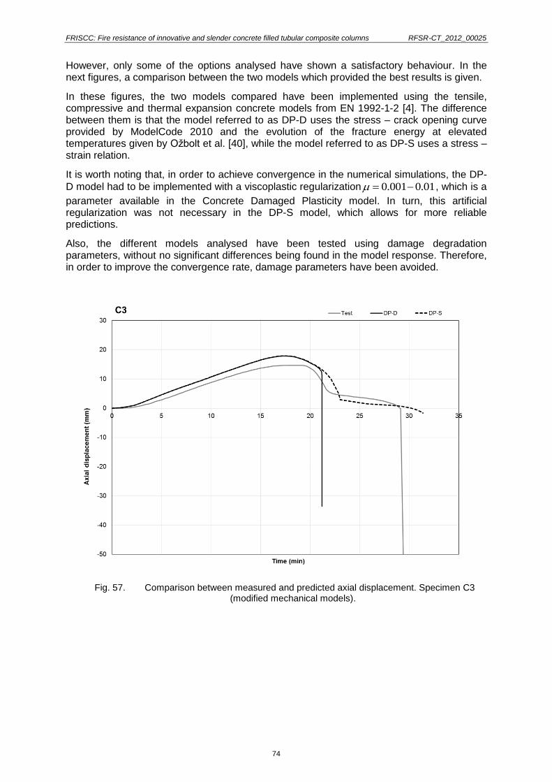
FRISCC: Fire resistance of innovative and slender concrete filled tubular composite columns RFSR-CT_2012_00025
74
However, only some of the options analysed have shown a satisfactory behaviour. In the next figures, a comparison between the two models which provided the best results is given.
In these figures, the two models compared have been implemented using the tensile, compressive and thermal expansion concrete models from EN 1992-1-2 [4]. The difference between them is that the model referred to as DP-D uses the stress – crack opening curve provided by ModelCode 2010 and the evolution of the fracture energy at elevated temperatures given by Ožbolt et al. [40], while the model referred to as DP-S uses a stress – strain relation.
It is worth noting that, in order to achieve convergence in the numerical simulations, the DP-
D model had to be implemented with a viscoplastic regularization 0.001 0.01 , which is a
parameter available in the Concrete Damaged Plasticity model. In turn, this artificial regularization was not necessary in the DP-S model, which allows for more reliable predictions.
Also, the different models analysed have been tested using damage degradation parameters, without no significant differences being found in the model response. Therefore, in order to improve the convergence rate, damage parameters have been avoided.
Fig. 57. Comparison between measured and predicted axial displacement. Specimen C3 (modified mechanical models).
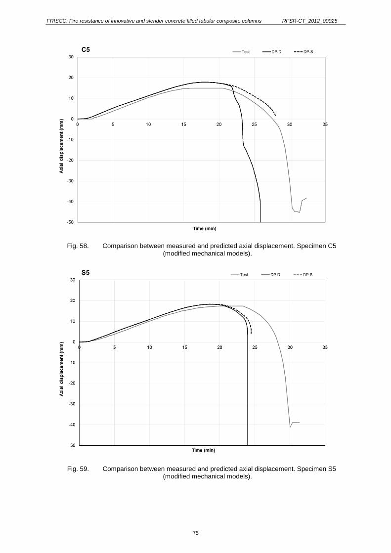
FRISCC: Fire resistance of innovative and slender concrete filled tubular composite columns RFSR-CT_2012_00025
75
Fig. 58. Comparison between measured and predicted axial displacement. Specimen C5 (modified mechanical models).
Fig. 59. Comparison between measured and predicted axial displacement. Specimen S5 (modified mechanical models).

FRISCC: Fire resistance of innovative and slender concrete filled tubular composite columns RFSR-CT_2012_00025
76
It can be observed that the modified DP-D model shows not accurate response for concentrically loaded specimens –see specimen C3- and sometimes leads to an unstable softening response like in specimen C5. This behaviour is a result of the viscoplastic regularization applied for obtaining convergence. This regularization parameter, needed to get convergence, introduces an unrealistic response, and therefore is not reliable for conducting future parametric studies.
In order to obtain convergence in models like DP-D with tension stiffening defined by stress – crack opening curves, without having to apply a viscoplastic regularization, different curves than that provided by ModelCode 2010 [23] have been tested. For instance, curves with a hyperbolic softening branch, which allow for a better convergence than the bi-linear curve from ModelCode 2010 have been tried. Nevertheless, it was not possible to reach successful results with this approach.
In conclusion, the DP-S model has shown a more accurate and realistic response than either of the options using stress – crack opening curves, therefore the DP-S model has been chosen for conducting the numerical simulations in the future tasks.
A comparison between the measured and predicted axial displacement versus time curves obtained by the previous model and the new model (DP-S) is shown in the following figures in order to support this conclusion.
Fig. 60. Comparison of measured and predicted axial displacement. Specimen – C3 (previous and modified model).

FRISCC: Fire resistance of innovative and slender concrete filled tubular composite columns RFSR-CT_2012_00025
77
Fig. 61. Comparison of measured and predicted axial displacement. Specimen – C5 (previous and modified model).
Fig. 62. Comparison of measured and predicted axial displacement. Specimen – S5 (previous and modified model).

FRISCC: Fire resistance of innovative and slender concrete filled tubular composite columns RFSR-CT_2012_00025
78
As it can be seen, the new modified model shows a more accurate response in terms of fire resistance time than the previous model, obtaining predictions which lie on the safe side for most of the cases analysed, being in all cases more safe-sided than the previous model.
It has been also intended that the different parameters used in the model are given from the Eurocodes, rather than from recommendations by other authors (i.e. concrete constitutive model in compression, thermal expansion coefficient, etc.), in order to obtain a model which is completely based on the Eurocodes, as future simplified design methods based on the results of parametric studies will be grounded on this model.
To sum up, the main features applied to new concrete mechanical model are:
Plastic material model Concrete Damaged Plasticity
Elastic behavior Temperature dependent from EN 1992-1-2
Thermal expansion Temperature dependent from EN 1992-1-2
Compression constitutive model Temperature dependent from EN 1992-1-2
Tension stiffening Stress – strain curve
Tensile strength Temperature dependent from EN 1992-1-2
The modified numerical model has been validated against the results of all the fire tests carried out on CHS and SHS columns within WP-2. A summary of the results obtained is given in Fig. 63 and Table 27 for CHS columns and Fig. 64 and Table 28 for SHS columns.
0
10
20
30
40
50
60
0 10 20 30 40 50 60
Pre
dic
ted
fa
ilu
re t
ime
(m
in)
Test failure time (min)
+15%
-15%
SAFE
UNSAFE
0
10
20
30
40
50
60
0 10 20 30 40 50 60
Pre
dic
ted
fail
ure
tim
e (
min
)
Test failure time (min)
+15%
-15%
SAFE
UNSAFE
a) Previous model (Drucker Prager) b) New model (Damaged Plasticity)
Fig. 63. Comparison between predicted and test failure time, circular columns.
Table 27. Results of the validation of the numerical model, circular columns
Column No. Previous model
Test/Num New model
Test/Num Test Num Test Num
C1 26 28.2 0.92 26 28.23 0.92
C2 30 31.56 0.95 30 32.53 0.92
C3 29 34.9 0.83 29 31.38 0.92
C5 29 30.96 0.94 29 28.04 1.03
Average 0.91 Average 0.95
Standard deviation 0.05 Standard deviation 0.06

FRISCC: Fire resistance of innovative and slender concrete filled tubular composite columns RFSR-CT_2012_00025
79
It should be noted that specimens C4 and C6 have not been included in this comparison, as the experimental results were not reliable due to an anomalous behaviour found during the corresponsing tests (see results of Task 2.3) and therefore they will not be used for the validation of the model.
0
10
20
30
40
50
60
0 10 20 30 40 50 60
Pre
dic
ted
fa
ilu
re t
ime
(m
in)
Test failure time (min)
+15%
-15%
SAFE
UNSAFE
0
10
20
30
40
50
60
0 10 20 30 40 50 60
Pre
dic
ted
fail
ure
tim
e (
min
)Test failure time (min)
+15%
-15%
SAFE
UNSAFE
a) Previous model (Drucker Prager) b) New model (Damaged Plasticity)
Fig. 64. Comparison between predicted and test failure time, square columns.
Table 28. Results of the validation of the numerical model, square columns
Column No. Previous model
Test/Num New model
Test/Num Test Num Test Num
S1 26 31.7 0.82 26 24.6 1.06
S2 23 33.3 0.69 23 33.3 0.69
S3 32 23.1 1.39 32 21.2 1.51
S4 54 50.9 1.06 54 39.6 1.36
S5 29 32.5 0.89 29 24.5 1.18
S6 29 39.8 0.73 29 30.6 0.95
Average 0.93 Average 1.13
Standard deviation 0.26 Standard deviation 0.29
It can be seen that, for both circular and square columns, the new model using a damaged plasticity definition of the concrete tensile behaviour provides predictions which are generally more safe-sided than the previous model, while representing with accuracy the evolution of the axial displacement of the columns during the whole fire exposure. A higher dispersion is found for the predictions of the square columns, which will be corrected through further refinement of the model.
During the next moths, the presented numerical model will be also validated with the results of the elliptical and rectangular columns to be tested in this project and, once validated for all the section shapes, it will be used for conducting the parametric study planned within WP3.

FRISCC: Fire resistance of innovative and slender concrete filled tubular composite columns RFSR-CT_2012_00025
80
b) Slender concrete-filled CHS/SHS/RHS/EHS columns in sub-frames (UC)
A three-dimensional numerical model has been developed for representing the behaviour of axially restrained composite columns subjected to fire [9], [41]. Such as observed in the real test set-up, a three-dimensional frame is performed to take into account not only the axial stiffness but also the rotational stiffness of the surrounding structure to the column (Fig. 65). Different values of stiffness are provided by positioning the peripheral columns of the restraining frame in different positions. With different values of the span, different values of axial and rotational stiffness were obtained.
Fig. 65. Numerical model used from UC.
The fire action is defined in ABAQUS by two types of surface, namely, “film condition” and “radiation to ambient”, corresponding respectively to heat transfer by convection and radiation. Radiation was considered with a resultant emissivity of 0.56 for steel and 0.49 for concrete. In other words, the emissivity of the furnace’s electric resistance and the emissivity of the steel and the concrete are taken as 0.7, 0.8 and 0.7, respectively. Finally, convection is considered with a coefficient of heat transfer by convection equal to 25 w/m2ºC, as recommended by EN1991-1-2 [3]. Lastly, a conduction coefficient of 200 W/m2K is adopted in the contact between the steel profile and the concrete.
Regarding the boundary conditions, all degrees of freedom of the nodes located on the bottom surface of the supports of the restraining frame are constrained and the initial temperature of all nodes of the numerical model was taken as 20 ºC. The load is applied on top of the upper beam, in several points, to prevent excessive deformation of the upper flange. The loading intended to simulate the serviceability load of a column when this one is inserted in a real building structure. Geometric imperfections are also considered as a bow out-of-straightness of L/1000 at mid-height of the column.
Solid elements, C3D8RT from the ABAQUS program library, are used for meshing all the parts. This element is defined as a three-dimensional (3D), continuum (C), hexahedral and an eight-node brick element with reduced integration, i.e. one integration point for each surface of the element (R), hourglass control and first-order (linear) interpolation. These finite elements have three degrees of freedom per node, referring to translations in the three directions X, Y and Z (global coordinates). C3D8RT is also a temperature element (T). ABAQUS evaluates the material response at each integration point, namely, stresses and strains. The stresses at the nodes are interpolated or extrapolated from the integration points to the nodes. So, the reduced integration decreases the amount of CPU time necessary for analysis of the model. However, reduced integration elements converge non-monotonically and due to this reduced number of integration points hourglassing can occur, so an hourglass stabilization control feature is built into the element to suppress spurious modes.

FRISCC: Fire resistance of innovative and slender concrete filled tubular composite columns RFSR-CT_2012_00025
81
c) Concrete-filled circular hollow section with embedded steel core profile (LUH)
The numerical simulation of composite columns at elevated temperature is covered by EN 1994-1-2. Nevertheless, there is a number of insufficiently investigated details using numerical models to design composite structures. In particular, the thermal and mechanical interface conditions between steel and concrete and the influence of residual stresses on the structural behaviour are uncertain. Within work package 3, it is the aim to set up a 3 D numerical model of a composite column with embedded steel core (CFSTES) in case of fire. Besides the formulation of the constitutive laws and material properties at high temperatures, the definition of both thermal and mechanical contact properties are focussed. Furthermore, the influence of residual stresses and structural imperfections are investigated in preliminary analysis.
The scope of level 1 and level 2 design methods in EN 1994-1-2 does not include composite columns with massive steel cores yet. Hence, for the structural fire design of those columns it is just possible to perform either advanced calculation methods or fire tests. Due to the high costs of fire tests, it is recommended to perform numerical simulations instead. In doing so, it is possible to investigate a wide range of parameters. On the other hand, there is a number of insufficiently investigated items, which need to be defined using numerical models. The treatment of those items may lead to significantly different results whereas they are not standardised. In general, the main difficulties in simulating composite columns in case of fire are listed hereafter and visualised in Fig. 66.
(1) implementation of constitutive laws, especially for concrete
(2) modelling of the interface between concrete and steel
(3) reproduction of the actual boundary conditions
(4) modelling of the load introduction
(5) approximation of structural and geometrical imperfections
(1)
(2)
(3)
(4)
(5)
Fig. 66. Distinctive details for numerical simulations of composite columns.
Within the project various types of composite columns are studied and several numerical models will be set up. The particular subject investigated at LUH is the innovative column type with embedded steel core. Those columns consist of a hollow steel section, a massive embedded steel core and concrete infill in between (see Fig. 67). This cross-section type comes along with a significantly increased load bearing capacity compared to other column types with identical outer dimensions. Hence, either higher loads can be applied or columns can be designed with smaller dimensions. Predominantly, circular columns with massive, circular embedded steel cores are studied.

FRISCC: Fire resistance of innovative and slender concrete filled tubular composite columns RFSR-CT_2012_00025
82
tube
concrete-infill
core
Fig. 67. Cross-section of concrete-filled column with embedded steel core.
Aiming at an optimised cross-sectional design, it is necessary to perform investigations and parametric studies on the limited concrete cover between steel tube and core, which is accompanied by a reduced fire protecting effect. The verification of a sufficient bearing capacity both for ambient and elevated temperatures is needed for this innovative column type.
The main research aim of this task is the realistic formulation of the composite action between the steel core and the concrete. It is striven to introduce the results of the experimental campaign into this work package and thus to introduce a temperature-dependent formulation of the composite action. Besides this, also the influence of heat transfer conditions and residual stresses within the cross-section concerning the thermal and structural behaviour of composite columns will be investigated.
Work undertaken
For the analysis performed within work package 3, the software package Abaqus 10.1 is used [1]. Accompanied with the Intel Fortran Compiler 10.1 it is furthermore possible to implement user-subroutines to Abaqus. For the planned introduction of a temperature-dependent formulation of the composite action, it is necessary to introduce e.g. the user-subroutine called FRIC.
Up to now, a preliminary numerical model of a CFSTES column was set up. As it was part of preliminary work, the dimensions are not yet the same as in the large column test. However, the model can easily be adapted to the actual dimensions. The important details that should be investigated with the numerical analysis are the same for the specimen modelled. The column dimensions exemplarily used in the model described have already been used in practical applications. The outer diameter of the tube amounts to 193.7 mm with a thickness of 4.5 mm. The steel core has a diameter of 70 mm. Hence, the thickness of the concrete cover arises to 57.35 mm. As the numerical simulation was inspired by fire tests of the project partners, the column length is chosen to 3.18 m according to their tests.
The investigated column has a symmetric cross-section, hence it is possible to reduce the model to a half-model. The half-model is still capable to reproduce all possible failure modes, whereas it has the advantage of a significantly reduced computing time.
Due to the introduction of residual stresses in the model, a coupled thermal-mechanical analysis is performed instead of the commonly used sequentially coupled. Hence, the elements chosen are coupled temperature-displacement elements. They are labelled C3D8T meaning three-dimensional elements with eight nodes and an additional degree of freedom for temperature. Linear shape functions and full integration are applied.
The cross-section is discretised in 28 elements along the circumference and 64 along the column length (see Fig. 68).

FRISCC: Fire resistance of innovative and slender concrete filled tubular composite columns RFSR-CT_2012_00025
83
(a)
(b)
Fig. 68. Discretisation of composite column and visualisation of C3D8-element.
MATERIAL PROPERTIES
Thermal analysis in Abaqus are based on the Fourier's equation. The specifications of EN 1994-1-2 are adopted concerning the temperature-dependent thermal material properties for steel and concrete. In accordance to the National Annex of Germany DIN EN 1994-1-2/NA [12], the upper limit of conductivity is utilised for concrete.
The peak value of the specific heat of concrete is dependent on the moisture content. Preliminary analysis showed that the assumption of 3 % moisture content leads to faster heating of the column than 10 % moisture content. Hence, the assumption of 3 % is conservative and applied to the model.
Regarding the thermal elongation coefficient of steel and concrete again the definitions of EN 1994-1-2 are adopted. Other authors, e.g. Hong & Varma [31], showed that the assumption
of constant values amounting to 1210-6 K-1 and 610-6 K-1 for steel and concrete respectively lead to quite similar results.
The simulation is performed with nominal values fy = 355 MPa for both steel tube and core and fc = 30 MPa for concrete, which corresponds to the material strengths proposed for the tests in task 2.5. The temperature-dependent decrease in material properties is adopted according to EN 1994-1-2. For both concrete and steel a temperature-dependent Poisson's ratio approximated from test results given in Ehm [14] and Wohlfahrt [46] is used (see Fig. 69).
There are several material models preset in Abaqus. For all material models it is necessary
to define the --relationship with true stresses and true strains. True stresses and true strains take into account the change in cross-sectional area in referring to the instantaneous area. Hence, the material values given in EN 1994-1-2 need to be transferred to true stresses and true strains before it is possible to adopt them in Abaqus.
For the isotropic material steel, the definition of the stress-strain-curve is equal for compression and tension. The elastic branch is specified with the predefined material model Elastic based on Hooke's law. The plastic branch-definition occurs via the material model Plastic. Furthermore, isotropic hardening is considered.
To reproduce the --relationship of concrete, the material model Concrete Damaged Plasticity is used for the plastic branch. This material model is based on the Drucker-Prager model and defines the 3 D-yield condition as a cone. For a realistic description of the yielding criterion a manipulation of the cone is possible via changing the eccentricity, the K-factor, the viscosity parameter and the dilatation angle. The eccentricity smoothes the top of the cone and is defined temperature-dependent according to Grassl (2006). According to Lubliner (1989), which is the basis of this model, the K-factor is taken to 2/3. The viscosity parameter is taken to zero by default. Any shear deformation is accompanied by an enlargement and change in volume of the material. This is described via the dilatation angle and depends on

FRISCC: Fire resistance of innovative and slender concrete filled tubular composite columns RFSR-CT_2012_00025
84
the grain shape and friction angle. For concrete the dilatation angle is commonly taken to 30°, which is adopted to the model.
Concrete
Steel
Fig. 69. Temperature-dependent Poisson's ratio.
The material model is furthermore capable to consider the increase in compressive strength in multi-axial stress states. The ratio of biaxial compressive strength and un-damaged uniaxial compressive strength is defined with temperature-dependent values in the model. A damage formulation for tensions and for compression is still in process at the Institute for Steel Construction.
CONTACT PROPERTIES
The interface between concrete and steel needs to be defined regarding mechanical and thermal contact properties. In case of fire, the outer steel tube of concrete-filled tubular columns heats up faster and expands more than the concrete-infill. Hence, the load bearing capacity decreases rapidly due to the high temperature and can be omitted (for detailed investigations of the outer tube see also Schaumann et al. (2009)). Consequently, it is conservative to neglect the mechanical contact in this joint due to the poor mechanical properties.
The cross-section investigated possesses a second joint between the concrete-infill and the steel core. Preliminary analysis showed that this joint does not separate during fire and hence mechanical contact is active. Both in normal and tangential direction contact properties need to be defined. In normal direction Hard contact is applied, transferring entire compressive forces but no tensile forces across the joint. The tangential behaviour is defined by Coulomb friction. Concerning the friction coefficient, various values have been used in
models of composite columns, e.g. = 0.6 (Hanswille [30]), = 0.6-0.8 (Goralski [24]) or
= 0.2-0.6 (Johansson [33]). A temperature-dependent friction coefficient cannot be found in literature yet. None of those authors proposed data for the friction coefficient at elevated temperature. Within the research project, this parameter will be studied in detail, whereas up
to now a constant value of = 0.6 is adopted.
Concerning the thermal contact property, the heat transfer is assumed to arise solely due to thermal conductance. Radiation and convection within gaps appearing during the analysis are neglected. Ideal conductance aims in conservative results, whereas a gap-dependent definition leads to more realistic temperatures. Another approach was introduced by Ding & Wang [13], utilising a constant value of 200 W/m²K for the heat transfer coefficient during the whole analysis.
A sensitivity study was carried out to investigate the influence of the conduction coefficient. The resulting temperatures within the cross-section are compared for ideal heat transfer and the approach proposed by Ding & Wang. The cross-section was heated by the ISO standard fire for 90 minutes. The results show significantly different temperatures reached in the

FRISCC: Fire resistance of innovative and slender concrete filled tubular composite columns RFSR-CT_2012_00025
85
middle of the core. The analysis using k = 200 W/m²K reaches 410 °C degree, whereas perfect heat transfer reaches 460 °C degree (see Fig. 70). The assumption of perfect heat transfer leads to higher temperatures, accompanied by a lower thermal gradient. The decrease in material properties due to higher temperatures is more decisive than the thermal gradient. Hence, an optimal heat transfer between concrete and steel is used for the analysis.
core = 409.6 °C core = 460.0 °C
Ding&Wang
k = 200 W/m²K
Optimal conductance Temperature
(°C)
Fig. 70. Temperature distribution through cross-section for different thermal contact properties.
BOUNDARY CONDITIONS AND LOAD INTRODUCTION
The boundary conditions are chosen to represent a pinned-fixed column with free axial and tangential expansion. The model possesses a symmetry plane, leading to a significantly reduced computing time.
Immediate and concentrated forces may cause instabilities in numerical calculation. To avoid this, a loading plate is introduced on top of the column, which is charged with uniform distributed compressive forces during a loading step. The loading plate is kept cold during the whole analysis. The interface between column and loading plate is defined by hard contact conditions.
IMPERFECTIONS
For consideration of geometrical imperfections, the first eigenmode of a preliminary buckle analysis is transferred to the model. The maximum amounting amplitude is scaled to 1/1000 of the column height.
Besides the aforementioned geometrical imperfections, structural imperfections are considered for the steel core as well. During the production process of massive steel cores residual stresses arise. Hamme & Schaumann [26] showed that contrary to thin steel cross-sections, massive steel profiles come along with residual stresses, which cannot be neglected due to their remarkable amount. In various parts of the cross-section, those residual stresses may reach the yield strength.
There is no standardised approach to consider residual stresses in numerical simulations. Some rare approaches can be found in literature. Hanswille [30] published a proposed stress distribution for massive circular steel profiles. In his approach, the amount of maximum tensile and maximum compressive stresses reach the same level. Compressive stresses develop in the outer regions, whereas in the inner area tensile stresses arise. In

FRISCC: Fire resistance of innovative and slender concrete filled tubular composite columns RFSR-CT_2012_00025
86
between, Hanswille proposes a quadratic stress distribution. The maximum amount of residual stresses varies with the diameter of the steel profile.
The cooling process was simulated in a secondary model in Abaqus. The process was simulated starting at 1200 °C and finishing when temperatures drop under 100 °C in each element. The comparison of maximum and minimum residual stresses resulting from the simulation and the simplified approach by Hanswille is shown in Fig. 71. The results match good for most investigated diameters. The simplified approach by Hanswille is able to predict the maximum and minimum arising residual stresses mainly conservative.
-1.50
-1.00
-0.50
0.00
0.50
1.00
1.50
100 200 300 400 500 600
R
,max
/min
/ f y
radius (mm)
Hanswille (2008)
numerical simulation
Fig. 71. Maximum and minimum residual stresses in massive circular steel sections.
Fig. 72 shows the stress distribution across the radius for various diameters. It is remarkable,
that for all diameters the zone of zero residual stresses is located 0.25-0.3r from the outer edge. This correlates to the parabolic approximation by Hanswille. On the other hand, the shape of the distribution in between only suites good to the parabolic approximation for large diameters. For small diameters especially the tensile zone in the centre flattens and does not match to the proposed distribution.
Both compared criterions, the maximum and minimum amount and the distribution of residual stresses, showed that the quadratic approximation is suitable as a simplified estimation. Nevertheless, a main criticism of this approach is, that it does not fulfill the basic characteristic of residual stresses whereas all stresses are in balance. Performing a preliminary coupled thermal-mechanical simulation and transferring the resulting stress distribution to the main model, this characteristic is fulfilled. In doing so it is capable to consider both structural and geometrical imperfections.

FRISCC: Fire resistance of innovative and slender concrete filled tubular composite columns RFSR-CT_2012_00025
87
-1.00
-0.60
-0.20
0.20
0.60
1.00
0 0.5 1
σR
/ f y
(-)
x / r (-)
D = 100 mm
D = 200 mm
D = 400 mm
D = 600 mm
r
x
Fig. 72. Residual stress distribution along the radius of massive circular steel profiles
Future work
The described 3D numerical model of a composite column with embedded massive steel core in case of fire needs to be refined in future time. Especially the introduction of a temperature-dependent formulation of the composite action between steel core and concrete needs to be established according to the results of the experimental campaign. At the moment preliminary studies are performed regarding the introduction of the user-subroutine FRIC in Abaqus. Those investigations need to be performed on smaller models, due to the fact that the afore described model is way too complex. Once the user-subroutine can be used for a temperature-dependent formulation of the composite action, it should be transferred to the model of the whole column.
Besides the composite action as well the constitutive laws for concrete need to be improved. Especially when tension arises within the concrete infill due to bending of the column, the numerical stability is not suitable with the actual model.
d) Slender concrete-filled EHS columns at room temperature (IMPERIAL)
To date, numerical analysis activities have focused on correctly modelling, in ABAQUS [1], the behaviour of confined concrete and the interaction between the concrete and steel, following from work by Espinos et al. [17], Sheehan et al. [44] and Dai et al. [10]. Previous experimental studies are used to refine and validate the present model.
Initially, in order to validate the steel material model (based on previous EHS coupon tests) and the overall analysis method, comparison was made with test result CI-200 h from Jamaluddin et al. [32], who conducted tests on a range of both hollow and concrete-filled EHS columns. A good agreement was found between the FE prediction and the experimental result for the deformed shape of the structure, and also for end shortening (Fig. 73 and Fig. 74).

FRISCC: Fire resistance of innovative and slender concrete filled tubular composite columns RFSR-CT_2012_00025
88
Fig. 73. Comparison of FE model (left) and test result of Jamaluddin et al. [32] for hollow stub column.
Fig. 74. Comparison of end shortening predicted by FEM (left) and observed by Jamaluddin et al. [32] (right).
Next, the focus of the FE modelling turned to concrete-filled steel tubes. In analyses of concrete-filled steel tubes (CFSTs), the effect of concrete confinement by the tube walls and reinforcement must be included. A stress-strain model of concrete confined by steel tubes was proposed by Han et al. [28], which was adopted by Dai et al. [10]; predictions made using this material model were found to converge well with experimental results.
Two material models have been examined at present to assess their suitability for modelling both stocky and slender concrete-filled steel tubes.
Stocky tubes – Drucker-Prager model
The Drucker-Prager model is designed to simulate pressure-dependent yield materials, and has been used in recent numerical studies of CFSTs. This material model assumes that the yield surface of the material dilates with increasing hydrostatic pressure.
Based on the research of Mander et al. [38], the confined strength and corresponding strain can be determined by the following equations, respectively:

FRISCC: Fire resistance of innovative and slender concrete filled tubular composite columns RFSR-CT_2012_00025
89
fcc = fck + k1 f1
ecc = eck(1+ k2
f1fck
)
Inclusion of the Drucker-Prager material model lends itself particularly well to modelling the deformation of shorter, stockier columns. Simulations conducted by Ellobody and Young [16], and Dai and Lam [11] using the Drucker-Prager model were found to converge very well with tests performed on concrete-filled stub columns
Slender columns – concrete damage plasticity model
The concrete damage plasticity model has been chosen to model the buckling of more slender concrete-filled steel tubes, using model parameters refined by Tao et al (2013).
Upon comparison of Test CII-200-C30 of Jamaluddin et al. [32] with the results of FE analysis using the concrete damage plasticity model, the ultimate resistance, failure load and deformation mode were found to converge well with the experimental results.
Fig. 75. Comparison of results of FE model (left) and test of Jamaluddin et al. [32] (right)
The focus of work at present is comparing the results of the full-scale CFEHS tests described previously with the FE predictions using these two models, with a view to refining the FE model further. Once the model has been successfully verified, it will then be used to perform parametric studies assessing the effect of different design parameters on the overall resistance of the concrete-filled elliptical hollow section members.

FRISCC: Fire resistance of innovative and slender concrete filled tubular composite columns RFSR-CT_2012_00025
90
As a preliminary validation against the experimental results obtained within this project, test specimen E15 has been simulated by means of the described numerical model, obtaining satisfactory results, as shown in Fig. 76 and Fig. 77, where the load versus end shortening and end rotation curves have been compared with the experimental results. The analysed specimen corresponds to a CFEHS column of 1 m long, with a minor axis loading eccentricity of 25 mm, unreinforced.
Fig. 76. Comparison between FE model and test result for specimen E15, load versus end shortening
Fig. 77. Comparison between FE model and test result for specimen E15, load versus end rotation

FRISCC: Fire resistance of innovative and slender concrete filled tubular composite columns RFSR-CT_2012_00025
91
2.2.4.- WP4. Simplified Design Methods.
This work package aims at correcting the current simplified methods of EN 1994-1.2 for circular and square CFST columns, extending the simplified methods to elliptical and rectangular CFST columns and developing new calculation rules for the fire resistance of circular concrete-filled tubular columns with embedded steel core profiles.
In this work package, safe and updated design rules for slender and innovative concrete-filled composite columns will be developed. The scope of the application of the simplified methods has been defined in WP-1. The simplified design methods to be developed within this work package will be based on the results of the experimental tests conducted in WP-2 and the parametric studies which will be carried out by means of the numerical models developed in WP-3.
As the number of test results from WP-2 (experimental tests) are limited, the analyses cases will be extended by means of parametric studies which will be performed in WP-3 (numerical simulations), through the numerical models validated against the previous experiments, and the results of these parametric studies will be taken as the base to develop the new simplified design methods.
This work package is divided in the following tasks:
Task 4.1 Extension of simplified design methods for circular and square CFST slender members (UPVLC and CTICM)
Task 4.2 Development of simplified design methods for rectangular and elliptical CFST columns for full slenderness range (UPVLC, CTICM and IMPERIAL)
Task 4.3 Development of simplified design methods for CHSES (CTICM and LUH)
Task 4.4 New design recommendations for Eurocode 4 part 1.2 (UPVLC, CTICM) and part 1.1 for elliptical (IMPERIAL)
The exact definition of the methods will be based on the results from WP-1: Evaluation of the existing design methods, but initial assumptions can be made.
At present, two options are available for the designers when calculating the axial resistance of concrete filled hollow sections columns in the fire situation to EN 1994-1-2:
- Utilization of Annex H (informative), based on the Guiaux and Janss method developed for composite hollow sections at room temperature, which is proved unsafe.
- Application of the general principles in Section 4.3.5.1 (as used for composite columns with partially encased steel sections in Annex G). However, the practical application is impossible, as the reduction coefficients to account for the effect of the thermal stresses are not given for the concrete filled hollow steel sections. In this situation, the common procedure has been to take them as equal to unity or bring them from Annex G.
The simplified method to be developed within this work package should deal with:
a) Temperature field calculation
Three possibilities can be proposed:
- Produce tables for different cross-sectional dimensions and geometries which collect
the temperature field at the standard fire exposure times (R30, 60, 90 and 120), as
already done by the CTICM group for circular and square sections.
- Calculate one equivalent temperature for the concrete core which gives the same fire
resistance of the column than through using the real non-uniform temperature
distribution, so that the designer can evaluate the fire resistance using a single
strength and stiffness value for each component of the composite column.

FRISCC: Fire resistance of innovative and slender concrete filled tubular composite columns RFSR-CT_2012_00025
92
- Use an approach similar to Annex G for composite columns with partially encased
steel sections, where the concrete core dimension is progressively reduced by
removing an exterior layer as the temperature advances through the cross-section.
An equivalent temperature is afterwards assigned to the reduced concrete core as a
function the fire exposure time and cross-sectional dimensions.
b) Influence of the load eccentricity For eccentric loads, a method is given in H.4 of Annex H, employing two correction coefficients as a function of the percentage of reinforcement and the load eccentricity (obtained from graphs), by means of which the applied load is corrected to obtain the fire resistance of the columns.
In this case, even when the reduction coefficients to account for the thermal stresses are taken as unity, the results obtained result on the safe side, although too far from the real response of the columns. It is therefore needed to study further if such method is appropriate and to support the values of the correction coefficients in numerical investigations.
The CTICM group has developed a new proposal for eccentrically loaded columns based on the same approach, including specific formulae for calculating the reduction coefficients.
Another option would be to employ an approach similar to the one of Annex G, Clause G.7 as suggested by Matti Leskela, which allows calculating the buckling resistance of the column in fire under eccentric load from the relation between the axial buckling load with and without eccentricity at room temperature.
The three methods exposed above (Clause H.4, CTICM proposal and Clause G.7) should be compared for a series of columns in order to find their level of accuracy and to be able to propose a new design method for eccentrically loaded columns.
Work undertaken
From the results of Task 1.4 (Evaluation of the existing design methods), some conclusions have been obtained about the level of accuracy of the current methods available in EN1994-1-2.
It was found that both methods in Eurocode 4 (general method and Annex H) result unsafe for slender columns subjected to concentric loads, while they produce safe – although too conservative – results for eccentrically loaded columns.
The partners involved in this work package are already working in the development of new simplified design methods which solve the current limitations of Eurocode 4. In particular, CTICM has developed a method for circular and square columns which is the base of the French National Annex [39], while UPVLC has developed a simple design model for the evaluation of the fire resistance of slender CFT columns of circular and elliptical section [21][19][18], subjected to concentric loads. These methods need to be extended and completed by means of the experimental and numerical results obtained in WP-2 and WP-3 within this project, which will be done during the course of this work package.

FRISCC: Fire resistance of innovative and slender concrete filled tubular composite columns RFSR-CT_2012_00025
93
2.2.5.- WP5- Design tools, dissemination and Code Additions
The objectives of the work package are:
- The creation of a user friendly design tool for slender and stub CFST columns which includes all the cross-sections analyzed in this research project.
- To disseminate the results of the project by the creation of specific workshop focussed to the steel industry and consulting firms.
- To propose an amendment to CEN/TC 250 /SC4 with the new design method.
Task 5.1 Workshop (IMPERIAL and CONDESA)
It is aimed that the results will be disseminated to the steel industry, the consulting firms and practitioners.
For that purpose, a specific workshop will be jointly organised by Imperial College and CONDESA to disseminate the findings of the project to the steel industry, practicing engineers and the research community. This workshop will also serve as an opportunity to showcase the benefits of tubular construction and CFST columns. In the last meeting of the project, the partners agreed that the event will be held in London by May/June 2015.
Task 5.2 Development of user friendly design tool (CTICM and CONDESA)
Based on their previous knowledge, CTICM will develop a user friendly design tool where the simplified design method developed in WP-4 will be implemented. This design tool will made simpler for the end user the practical application of the proposed method. In turn, CONDESA will test the use of this software with practical applications.
At the moment, CTICM has two software tools available, which can be used as a basis for the development of the design tool for this project: POTFIRE and A3C. In particular, the software will be developed under Visual Basic on the basis of A3C, which has been used in the past for evaluating the fire resistance of steel profiles and partially encased composite columns, and will be extended in this task for the application of the new method to all the different types of sections studied in this project. The interface of this software is attractive and will be easy to use by all applicators.
In accordance with the structural solutions which are investigated in the scope of this project, the software to be developed will deal with following column cross-sections:
- Normal concrete filled steel tubes: circular and square cross-sections with and
without reinforcement.
- New types of concrete filled steel tubes: elliptical and rectangular cross-sections with
and without reinforcement.
- Concrete filled steel tubes with embedded steel core: circular section with internal
massive steel core profiles.
Some work has been already done by CTICM regarding the design of the interface of the design tool. The main characteristics of the future design tool are described next.
In the main data window, the length, orientation, bending axis, support conditions and distance between members will be introduced by the user. Another window will prompt the used to introduce the material data (Fig. 78 to Fig. 80), with the possibility to choose the steel profile from a catalogue of cross-sections. The concrete compressive strength, moisture content and density, as well as the yield strength of structural steel can be introduced. It will be also possible to choose the addition of reinforcing bars or solid steel core.

FRISCC: Fire resistance of innovative and slender concrete filled tubular composite columns RFSR-CT_2012_00025
94
Steel profile
Concrete core
Reinforcement
Cross-section geometry
Fig. 78. Example of the interface for the input data (elliptical section with no reinforcement).
Concrete core
Steel rebars
Steel profile
Cross-section geometry
Fig. 79. Example of the interface for the input data (square section with steel rebars).

FRISCC: Fire resistance of innovative and slender concrete filled tubular composite columns RFSR-CT_2012_00025
95
Steel profile
Concrete core
Steel core
Cross-section geometry
Fig. 80. Example of the interface for the input data (circular section with embedded steel core).
For room temperature design, the load cases and combination factors can be introduced, as well as the axial force and end moments.
The software is also designed for the evaluation of the fire resistance of concrete-filled tubular columns (Fig. 81). Two calculation options are allowed for: fire resistance from a given applied load or buckling resistance for a given fire exposure time. The temperature field can be evaluated using either the finite differences method, tabulated data or analytical formulae. The tables and equations developed in WP-4 for evaluating the cross-sectional temperature filed will be implemented here. The heat transfer parameters and column buckling length in the fire situation need to be also introduced. Also the load combinations for the fire design situation can be chosen.

FRISCC: Fire resistance of innovative and slender concrete filled tubular composite columns RFSR-CT_2012_00025
96
Calculation options
Temperature field assessment
Column position to get the buckling length in fire
Heat transfer parameters
Fig. 81. Fire resistance calculation window.
The calculation results window will include the verification of the cross-section resistance and element stability criteria for room temperature design as well as the results of the fire design calculation. A calculation sheet can be obtained with the results of all the calculations performed, for which an example is given in Fig. 82.

FRISCC: Fire resistance of innovative and slender concrete filled tubular composite columns RFSR-CT_2012_00025
97
Fig. 82. Example of a calculation sheet.
Task 5.3 Proposal for code additions
UPVLC and CTICM are both members of the committee of CEN/TC 250/SC4 and also from the ad-hoc group for the modification of the current Annex H in EN1994-1-2, so the results which are obtained in this project will be directly proposed to be included in future revisions of Eurocode 4 Part 1.2. This will be done when the work of WP-4 will be completed.

FRISCC: Fire resistance of innovative and slender concrete filled tubular composite columns RFSR-CT_2012_00025
98
2.2.6.- WP6. Coordination
This work programme includes: - Monitoring of time schedule. - Relationship with partners to monitor progress. - Organisation and running progress meetings. - Dissemination of results. - Project administration.
Work undertaken
Three meetings have taken place in this reporting period. The kick-off meeting took place at the offices of SCMF Syndicat de la Construction Metallique in Paris, France in September 2012. At this meeting, the project was discussed in a holistic sense and work/material requirements/data was shared between the partners.
The second meeting was held in Hannover in February 2013 and each of the partners updated the rest of the team about their past and future activities. Also, a workshop on the finite element modelling of innovative concrete-filled tubular columns under room and elevated temperatures was celebrated in LUH on the occasion of the meeting, where all the partners involved in the numerical simulations (WP-3) participated.
The third meeting was celebrated in UPVLC in September 2013, where the planning of the experimental tests to be carried out by the different partners was done, as well as the preparation for WP-3 (numerical simulations). Taking advantage of the early commencement of the experimental program carried out by UPVLC-AIDICO, the partners were taken to see one of the fire tests, which was performed in AIDICO on the next day of the meeting.
A website has been developed for use by the project’s partners to enable quick and efficient communications throughout the project. Documents and information such as minutes of meetings, contact details and technical reports are being posted on the website.
The link for the website of the project is given next:
http://friscc.blogs.upv.es
Future work
The Coordination activities include arranging input and circulation of documents via the FRISCC project website managed by UPVLC, organization of future meetings and preparation of the annual reports.

FRISCC: Fire resistance of innovative and slender concrete filled tubular composite columns RFSR-CT_2012_00025
99
2.3.- Preliminary conclusions
During this reporting period, comprising the first 18 months of the project, all the tasks in WP-1 have been finished and the corresponding deliverables (1.1, 1.2, 1.3 and 1.4) submitted, as well as Task 2.1 with deliverable 2.1, consisting of the design of the test specimens and corresponding setup. Tasks 2.2 to 2.5 in WP-2 are currently in course, where the different partners are carrying out their corresponding tests. In turn, WP-3 (numerical simulations), WP-4 (simplified design methods) and Task 5.2 within WP-5 have recently started.
In WP-1, the current usage of concrete-filled tubular columns was reviewed, as well as the results of the tests available in the literature from previous experimental programs. All this work allowed, on the one hand, to detect the actual needs of the construction market, and on the other hand, to define the test parameters for the experimental program to be carried out in WP-2. While a great number of previous tests on circular and square CFT columns were found in the literature, few cases on rectangular or elliptical columns filled with concrete were found, which justifies the need for further tests to be carried out in this project. Also the existing design methods were reviewed, finding that the methods in Eurocode 4 result unsafe for slender columns subjected to concentric load, while they produce safe – although too conservative – results for eccentrically loaded columns. Other methods existing worldwide were evaluated, as those used in North America, China and Japan, for which some shortcomings were also observed. Therefore, a new simple calculation model which improves the accuracy of the current calculation methods and extends their applicability limits is needed, which will be one of the aims of this European Project.
Regarding WP-2, experimental tests, the test specimens to be tested and the corresponding test setup have been defined by all the partners, and some of the tests have already started. In particular, UPVLC-AIDICO are conducting the fire tests on isolated columns, UC is testing columns in sub-frames, LUH is preparing the fire tests on concrete-filled CHS with embedded steel core profile and IMPERIAL has recently started the room temperature tests on concrete-filled EHS columns. From the fire tests on isolated columns, which are being conducted by UPVLC-AIDICO (26 out of 36 tests already carried out), it has been found that, for the same steel usage, the circular columns present a better fire performance than the square columns. Additionally, for the same column dimensions and percentage of reinforcement, the fire resistance time is significantly reduced when applying the load eccentrically. Furthermore, it has been found that for the same load eccentricity, when the percentage of reinforcement is increased, the fire resistance time also increases. These results are also confirmed with the elliptical and rectangular columns test results, although the comparisons between these two shapes do not allow to obtain a definitive conclusion on their relative fire performance, as the part of the experimental program corresponding to elliptical and rectangular columns is still in process and more results are to be obtained.
The development and validation of the numerical models from the different partners is being carried out within WP-3. Initial numerical models have been developed for representing the different types of situations to study. The parameters of these preliminary numerical models have been initially calibrated by comparison with test results available in the literature. At the moment, the numerical models are being validated against the test results obtained in WP-2, work which is being carried out in parallel to the development of the experimental tests. For the moment, the agreement between the simulation results and test results is satisfactory, although the numerical models still need to be refined through the validation against all the test results before conducting the parametric studies.
A review on the methods available in the literature and the different building codes for evaluating the fire resistance of concrete-filled tubular columns has been carried out as a preliminary work in WP-4. The partners involved in this work package are already working in the development of new simplified design methods which solve the current limitations of Eurocode 4. These methods need to be extended and completed by means of the experimental and numerical results obtained in WP-2 and WP-3 within this project, which will be done during the course of this work package.

FRISCC: Fire resistance of innovative and slender concrete filled tubular composite columns RFSR-CT_2012_00025
100
The development of the user friendly design tool in Task 5.2 within WP-5 has also started. A preliminary design of the interface of this design tool has been done based on an existing calculation software by CTICM. As soon as the results from WP-4 are ready, the developed simplified design methods will be implemented in this software.
To sum up, the course of the project is in good progress at the moment, following the schedule established in the initial planning, and partial conclusions have been already obtained, which need to be verified with the results of the remaining experimental tests and further numerical simulations.
2.4.- Publications and patents
Papers published in scientific journals
1 A. Espinós, M.L. Romero, J.M. Portolés, A. Hospitaler. Ambient and fire behaviour of eccentrically loaded elliptical slender concrete-filled tubular columns. Journal of Constructional Steel Research (under evaluation)
2 A. Espinós, M.L. Romero, A. Hospitaler. Finite element analysis of the fire behaviour of concrete filled circular hollow section columns. Workshop “Finite element modelling of innovative concrete-filled tubular columns under room and elevated temperatures”, pp. 3 - 12. Editorial Universitat Politècnica de València, 2013. ISSN 978-84-9048-123-3
Papers submitted to conferences
Title: Experimental investigation on the fire resistance of slender concrete filled tubular columns of different cross-section shape
Authors: A. Espinós, M. L. Romero, E. Serra, V. Albero
Name of the conference: Eurosteel 2014
Location: Napoli, Italy
Data: 10-12/09/2014
Organizing entity: ECCS (European Covention for Constructional Steelwork)
Title: Fire resistance of circular and square slender concrete filled tubular columns subjected to large eccentricities
Authors: A. Espinós, M. L. Romero, E. Serra, A. Hospitaler
Name of the conference: Structures in Fire (SIF) 2014
Location: Shanghai, China
Data: 11-13/06/2014
Organizing entity: Tongji University

FRISCC: Fire resistance of innovative and slender concrete filled tubular composite columns RFSR-CT_2012_00025
101
REFERENCES
[1] ABAQUS. 2013. ABAQUS/Standard Version 6.13 User’s Manual: Volumes I-III.
Pawtucket, Rhode Island: Hibbitt, Karlsson & Sorensen, Inc.
[2] Association of New Urban Housing Technology (ANUHT). 2004. Fire resistance design
of non-insulated CFT columns – Guidelines, technical explanations and design
examples (in Japanese).
[3] CEN. EN 1991-1-2. Eurocode 1: Basis of Design and Actions on Structures – Part 1-2:
Actions on Structures Exposed to Fire. Brussels, Belgium: Comité Européen de
Normalisation, 2002.
[4] CEN. EN 1992-1-2, Eurocode 2: Design of concrete structures, Part 1.2: General rules –
Structural fire design. Brussels, Belgium: Comité Européen de Normalisation, 2004.
[5] CEN. EN 1993-1-2, Eurocode 3: Design of steel structures, Part 1.2: General rules –
Structural fire design. Brussels, Belgium: Comité Européen de Normalisation, 2005.
[6] CEN. EN 1994-1-1, Eurocode 4 – Design of composite steel and concrete structures –
Part 1-1: General rules and rules for buildings. Brussels, Belgium: Comité Européen de
Normalisation, 2005.
[7] CEN. EN 1994-1-2, Eurocode 4 – Design of composite steel and concrete structures –
Part 1-2: General rules – Structural fire design. Brussels, Belgium: Comité Européen de
Normalisation, 2006.
[8] Cométube. Détermination de la durée au feu des profils creux remplis de béton. Final
report project.
[9] Correia AJPM, Rodrigues JPC. 2011. Fire resistance of partially encased steel columns
with restrained thermal elongation. Journal of Constructional Steel Research 67:593-
601.
[10] Dai X, Lam D, Jamaluddin N, Ye, J. 2014. Numerical analysis of slender elliptical
concrete filled columns under axial compression. Thin-Walled Structures, 77, 26-35.
[11] Dai X, Lam D. 2010. Numerical modelling of the axial compressive behaviour of short
concrete-filled elliptical steel columns. Journal of Constructional Steel Research, 66 (7),
931-942.
[12] DIN EN 1994-1-2/NA 2010. Nationaler Anhang - National festgelegte Parameter -
Eurocode 4: Bemessung und Konstruktion von Verbundtragwerken aus Stahl und Beton
– Teil 1-2: Allgemeine Regeln – Tragwerksbemessung für den Brandfall. Deutsches
Institut für Normung, Beuth Verlag, Berlin.
[13] Ding J, Wang YC. 2008. Realistic modelling of thermal and structural behaviour of
unprotected concrete filled tubular columns in fire. Journal of Constructional Steel
Research 64:1086-1102.
[14] Ehm C. 1986. Versuche zur Festigkeit und Verformung von Beton unter zweiachsialer
Beanspruchung und hohen Temperaturen. Forschungsbericht, Heft 71. Braunschweig:
Institut für Baustoffe, Massivbau und Brandschutz, Technische Universität
Braunschweig.

FRISCC: Fire resistance of innovative and slender concrete filled tubular composite columns RFSR-CT_2012_00025
102
[15] Elghazouli A, Izzuddin B, Cashell K. 2009. Experimental evaluation of the mechanical
properties of steel reinforcement at elevated temperature. Fire Safety Journal, 44, 909-
919.
[16] Ellobody E, Young B. 2006. Nonlinear analysis of concrete-filled steel SHS and RHS
columns. Thin-walled structures, 44 (8), 919-930.
[17] Espinos A, Romero ML, Hospitaler A. 2010. Advanced model for predicting the fire
response of concrete filled tubular columns. Journal of Constructional Steel Research
66(8–9):1030-1046.
[18] Espinos A, Romero ML, Hospitaler A. Fire design method for bar-reinforced circular and
elliptical concrete filled tubular columns. Engineering Structures 2013; 56:384-395.
[19] Espinos A, Romero ML, Hospitaler A. Simple calculation model for evaluating the fire
resistance of unreinforced concrete filled tubular columns. Engineering Structures 2012;
42:231-244.
[20] Espinos A. 2012. Numerical analysis of the fire resistance of circular and elliptical
slender concrete filled tubular columns. Doctoral thesis. Valencia, Spain: Universitat
Politècnica de València.
[21] Espinos A., Romero M., Development of a simple calculation model for evaluating the
fire resistance of concrete filled tubular columns, Research report, Universitat Politècnica
de València, 2013.
[22] European Federation of Specialist Construction Chemicals and Concrete Systems
(EFNARC). 2005. European Guidelines for Self Compacting Concrete – Specification,
Production and Use. EFNARC.
[23] FIB. 2012. ModelCode 2010. Volume 1. Lausanne, Switzerland: International Federation
for Structural Concrete.
[24] Goralski C. 2006. Zusammenwirken von Beton und Stahlprofil bei kammerbetonierten
Verbundträgern. PhD thesis. Rheinisch-Westfälische Technische Hochschule Aachen.
[25] Grassl P, Jirasek M. 2006. Damage-plastic model for concrete failure. International
Journal of Solids and Structures 43:7166-7196.
[26] Hamme U, Schaumann P. 1987. Rechnerische Analyse von Walzeigenspannungen.
Stahlbau 56:328-334.
[27] Han LH, Yao GH, Tao Z. 2007. Performance of concrete-filled thin-walled steel tubes
under pure torsion. Thin-Walled Structures, 45(1), 24–36.
[28] Han LH, Yao GH, Zhao X. 2005. Tests and calculations for hollow structural steel (HSS)
stub columns filled with self-consolidating concrete (SCC). Journal of Constructional
Steel Research, 61 (9), 1241-1269.
[29] Han LH, Zhao XL, Yang YF, Feng JB. 2003. Experimental study and calculation of fire
resistance of concrete-filled hollow steel columns. Journal of Structural Engineering
(ASCE) 129(3):346-356.
[30] Hanswille G, Lippes M. 2008. Einsatz von hochfesten Stählen und Betonen bei
Hohlprofil-Verbundstützen. Stahlbau 77:296-307.

FRISCC: Fire resistance of innovative and slender concrete filled tubular composite columns RFSR-CT_2012_00025
103
[31] Hong S, Varma AH. 2009. Analytical modeling of the standard fire behavior of loaded
CFT columns. Journal of Constructional Steel Research 65:54-69.
[32] Jamaluddin N, Lam D, Dai XH, Ye J. 2013. An experimental study on elliptical concrete
filled columns under axial compression. Journal of Constructional Steel Research, 87, 6–
16.
[33] Johansson M, Gylltoft, K. 2002. Mechanical Behaviour of Circular Steel-Concrete
Composite Stub Columns. Journal of Structural Engineering. 1073-1081.
[34] Kodur VKR, MacKinnon DH. 2000. Design of concrete-filled hollow structural steel
columns for fire endurance. Engineering Journal-AISC 37(1):13-24.
[35] Lie TT, Chabot M. 1992. Experimental studies on the fire resistance of hollow steel
columns filled with plain concrete. Internal report No. 611. Ottawa, Canada: Institute for
Research in Construction, National Research Council of Canada (NRCC).
[36] Lie TT. 1994. Fire resistance of circular steel columns filled with bar-reinforced concrete.
Journal of Structural Engineering-ASCE 120(5): 1489-1509.
[37] Lubliner J, Oliver J, Oller S, Onate E. 1989. A plastic-damage model for concrete.
International Journal of Solids and Structures 25:299-326.
[38] Mander JB, Priestley MJ, Park R. 1988. Theoretical stress-strain model for confined
concrete. Journal of Structural Engineering, ASCE, 114 (8), 1804-1826.
[39] NF EN 1994-1-2/NA, Eurocode 4 – Design of composite steel and concrete structures –
Part 1-2: General rules – structural fire design – National Annex to NF EN 1994-1-
2:2006, 2007.
[40] Ožbolt J et al. 2014. 3D numerical analysis of reinforced concrete beams exposed to
elevated temperature. Engineering Structures 58: 166-174.
[41] Pires TAC, Rodrigues JPC, Silva JJR. 2012. Fire resistance of concrete filled circular
hollow columns with restrained thermal elongation. Journal of Construction Steel
Research 77:82-94.
[42] Romero ML, Moliner V, Espinos A, Ibañez C, Hospitaler A. 2011. Fire behavior of axially
loaded slender high strength concrete-filled tubular columns. Journal of Constructional
Steel Research 67(12):1953-1965.
[43] Schaumann P, Kodur V, Bahr O. 2009. Fire Behaviour of hollow structural section steel
columns filled with high strength concrete. Journal of Constructional Steel Research
65:1794-1802.
[44] Sheehan T, Dai XH, Chan TM, Lam D. 2012. Structural response of concrete-filled
elliptical steel hollow sections under eccentric compression. Engineering Structures, 45,
314–23.
[45] Tao Z, Wang Z, Yu Q. 2013. Finite element modelling of concrete-filled steel stub
columns under axial compression. Journal of Constructional Steel Research, 89, 121-
131.
[46] Wohlfahrt H. 2001. Simulation der Vorgänge im Schmelzbad beim Laserstrahlschweißen
zur Voraussage von Nahtausbildung, Gefüge, Verzug und Schweißeigenspannungen.

FRISCC: Fire resistance of innovative and slender concrete filled tubular composite columns RFSR-CT_2012_00025
104
Forschungsbericht. Braunschweig: Institut für Schweißtechnik, Technische Universität
Braunschweig.
[47] Yang H, Lam D, Gardner L. 2008. Testing and analysis of concrete-filled elliptical hollow
sections. Engineering Structures, 30, 3771–3781.
[48] Zhao XL, Packer JA. 2009. Tests and design of concrete-filled elliptical hollow section
stub columns. Thin-Walled Structures, 47, 617–628.

FRISCC: Fire resistance of innovative and slender concrete filled tubular composite columns RFSR-CT_2012_00025
105
II. Copy of the signed Technical Annex