Embed Size (px)
Citation preview

- 1 -
MARINE GUIDANCE NOTE
MGN 382 (M)
Fire Protection of Balconies and Other ExternalAreas on Passenger Ships
Notice to all Shipowners, Shipbuilders, Masters and Officers of Ships
PLEASE NOTE:-Where this document provides guidance on the law it should not be regarded as definitive.The way the law applies to any particular case can vary according to circumstances - forexample, from vessel to vessel and you should consider seeking independent legal advice ifyou are unsure of your own legal position.
Summary
This notice draws attention to:
amendments to SOLAS entered into force on 1st July 2008, which apply to cabinbalconies on passenger ships,
design requirements for the fire detection and fire suppression systems which may befitted in compliance with these SOLAS amendments, and
IMO guidelines for evaluating fire risk of other external areas on passenger ships.
1 New fire protection requirements for cabin balconies
1.1 Amendments to SOLAS Chapter II-2 have been adopted by IMO as Annex 1 to resolutionMSC.216(82), in response to the balcony fire in March 2006 on cruise ship Star Princess1.The amendments, which entered into force on the 1st July 2008 introduce new fire safetyrequirements for cabin balconies on passenger ships to which the Convention applies.These SOLAS amendments have yet to be implemented in the MCA’s SOLAS 2002Chapter II-2 Publication, which is given effect to by the Merchant Shipping (Fire Protection)Regulations 2003, and in the Merchant Shipping (Fire Protection: Large Ships) Regulations1998. It should be noted that the amendments contain certain requirements applicable toships built before, as well as after, 1st July 2008.
1.2 The amendments provide for:
(a) divisions between individual balconies to be of non combustible material (as defined inISO 1182+FTP Code2) on existing and new ships, and to be openable (to allow accessfrom adjacent balcony or deck) on new ships,
(b) surface finishes (except hardwood decking) to be of low flame spread type (as definedin IMO resolution A.653(16)) and such finishes other than deck coverings to be limited as

- 2 -
to calorific potential (when measured according to the method of ISO 1716) on existing andnew ships,
(c) surface finishes to not be capable of producing excessive smoke and toxic products ofcombustion (according to IMO resolution MSC.41(64)) on new ships,
(d) primary deck coverings to be not capable of producing smoke or toxic or explosivehazards (A.653(16)+A.687(17), MSC41(64)) on new ships,
(e) all balcony furniture and furnishings to either comply with the specification for furnitureand furnishings of restricted fire risk, or (i) fire detection and fire alarm system(MSC.1/Circ.1242) and (ii) fixed pressure water spraying system (MSC.1/Circ.1268) are tobe fitted on new and existing ships.
1.3 The relevant provisions apply as from 1st July 2008 in the case of ships constructed on orafter that date, referred to above as new ships, and on the date of the first surveythereafter in the case of existing ships. The text of the amendments is reproduced inAnnex 1 to this notice.
1.4 The requirements referenced at 1.2 (e) above are supported by circulars MSC.1/Circ.1242and MSC.1/Circ. 1268 which contain design requirements for the respective systems. Thefirst of these was promulgated by and appended to Marine Guidance Notice MGN 367 (M).MSC .1/Circ 1268 is reproduced in Annex 2 to this notice. The design guidance in thesecirculars is primarily for the information of bodies issuing type approval certificates for therelevant system components.
1.5 It is possible that some shipowners may have installed fire detection or fire extinguishingsystems on cabin balconies of passenger ships before the adoption by IMO of the relevantcirculars Circ.1242 or Circ.1268. In order that such systems can continue to be used onUK ships, provided they remain effective, the following requirements should be satisfied.
(a) in the case of water spraying fire extinguishing systems it should be possible todemonstrate effective spray coverage of the deck area of any balcony and the system flowrate should generally be sufficient to simultaneously supply three or more adjacentbalconies; and
(b) in the case of fire detection and alarm systems, the system should be operated by heat,smoke or other product of combustion or by flame on each balcony, arranged to give avisual or audible alarm at a manned control station or similar manned space; the detectorheads should comply with a recognised standard, and be capable of being tested forcorrect operation and restored to normal surveillance without renewal of any component.
2. Design and operational guidelines for external areas on passenger ships.
2.1 Concurrent with the work on fire protection of cabin balconies, IMO developed guidelinesfor designers and operators to address fire risk of external areas of passenger ships otherthan on cabin balconies. The guidelines are published as MSC.1/Circ.1274, which isreproduced in Annex 3. The guidelines are not intended to apply to external areas for thecarriage of cargoes or vehicles.
1. Report on the investigation of the fire onboard Star Princess off Jamaica 23rd March 2006. ReportNo 28/2006 obtainable from Marine Accident Investigation Branch, Carlton House, Carlton Place,Southampton SO15 2DZ
2. International Code for Application of Fire Test Procedures. Sales Nr. IMO-844E, from InternationalMaritime Organization, 4 Albert Embankment, London SE1 7SR

- 3 -
More Information
Marine Technology UnitMaritime and Coastguard AgencyBay 2/29Spring Place105 Commercial RoadSouthamptonSO15 1EG
Tel : +44 (0) 23 8032 9119Fax : +44 (0) 23 8032 9161e-mail: [email protected]
General Inquiries: [email protected]
MCA Website Address: www.mcga.gov.uk
File Ref: MS 22/11/532
Published: November 2008Please note that all addresses andtelephone numbers are correct at time of publishing
© Crown Copyright 2008
Safer Lives, Safer Ships, Cleaner Seas
Printed on material containing minimum 75% post-consumer waste paper

- 4 -
ANNEX 1CHAPTER II-2
CONSTRUCTION – FIRE PROTECTION, FIRE DETECTION ANDFIRE EXTINCTION
Regulation 1 – Application
2 In paragraph 2.2.3, the second occurrence of the word “and” is deleted.
3 In paragraph 2.2.4, “.” is replaced by “; and”.
4 In paragraph 2.2, the following new subparagraph .5 is added after the existing subparagraph .4:“5 regulations 5.3.1.3.2 and 5.3.4 to passenger ships not later than the date of the first surveyafter 1 July 2008.”
Regulation 3 – Definitions
5 The following new paragraph 53 is added after the existing paragraph 52:“53 Cabin balcony is an open deck space which is provided for the exclusive use of theoccupants of a single cabin and has direct access from such a cabin.”
Regulation 4 – Probability of ignition
6 The following text is added at the end of paragraph 5.2.3:“except that “A-0” class standard is acceptable for windows and sidescuttles outside the limitspecified in regulation 9.2.4.2.5.”
7 In paragraph 4.4, the words “or if applied on cabin balconies of passenger ships constructed onor after 1 July 2008,” are added between the words “stations” and “shall”.
Regulation 5 – Fire growth potential
8 In paragraph 3.1.2.1, the last sentence is deleted.
9 The following new paragraph 3.1.3 is inserted:
“3.1.3 Partial bulkheads and decks on passenger ships
3.1.3.1 Partial bulkheads or decks used to subdivide a space for utility or artistic treatment shallbe of non-combustible materials.
3.1.3.2 Linings, ceilings and partial bulkheads or decks used to screen or to separate adjacentcabin balconies shall be of non-combustible materials. Cabin balconies on passenger shipsconstructed before 1 July 2008 shall comply with the requirements of this paragraph by the firstsurvey after 1 July 2008.”
10 In the first sentence of paragraph 3.2.1.1, the words “and cabin balconies” are added betweenthe words “spaces” and “which”, and the following new sentence is added at the end of theparagraph:
“However, the provisions of paragraph 3.2.3 need not be applied to cabin balconies.”
- 5 -
11 The following new subparagraph .3 is added to the existing paragraph 3.2.4.1:“.3 exposed surfaces of cabin balconies, except for natural hard wood decking systems.”
12 The following new paragraph 3.4 is added after the existing paragraph 3.3:“3.4 Furniture and furnishings on cabin balconies of passenger shipsOn passenger ships, furniture and furnishings on cabin balconies shall comply with regulations3.40.1, 3.40.2, 3.40.3, 3.40.6 and 3.40.7 unless such balconies are protected by a fixed pressurewater-spraying and fixed fire detection and fire alarm systems complying with regulations 7.10and 10.6.1.3. Passenger ships constructed before 1 July 2008 shall comply with therequirements of this paragraph by the first survey after 1 July 2008.”
Regulation 6 – Smoke generation potential and toxicity
13 The existing paragraph 2 is renumbered as paragraph 2.1.
14 The following new paragraph 2.2 is added after the renumbered paragraph 2.1:
“2.2 On passenger ships constructed on or after 1 July 2008, paints, varnishes and other finishesused on exposed surfaces of cabin balconies, excluding natural hard wood decking systems,shall not be capable of producing excessive quantities of smoke and toxic products, this beingdetermined in accordance with the Fire Test Procedures Code.”
15 The existing paragraph 3 is renumbered as paragraph 3.1.
16 The following new paragraph 3.2 is added after the renumbered paragraph 3.1:“3.2 On passenger ships constructed on or after 1 July 2008, primary deck coverings on cabinbalconies shall not give rise to smoke, toxic or explosive hazards at elevated temperatures, thisbeing determined in accordance with the Fire Test Procedures Code.”
Regulation 7 – Detection and alarm
17 The following new paragraph 10 is added after the existing paragraph 9.4:
“10 Protection of cabin balconies on passenger ships
A fixed fire detection and fire alarm system complying with the provisions of the Fire SafetySystems Code shall be installed on cabin balconies of ships to which regulation 5.3.4 applies,when furniture and furnishings on such balconies are not as defined in regulations 3.40.1, 3.40.2,3.40.3, 3.40.6 and 3.40.7.”
Regulation 9 – Containment of fire
18 The following new paragraph 2.2.6 is added after the existing paragraph 2.2.5.2:
“2.2.6 Arrangement of cabin balconies
On passenger ships constructed on or after 1 July 2008, non-load bearing partial bulkheadswhich separate adjacent cabin balconies shall be capable of being opened by the crew from eachside for the purpose of fighting fires.”
Regulation 10 – Fire fighting
19 The heading of paragraph 6.1 is replaced by the following:
“6.1 Sprinkler and water spray systems in passenger ships”

- 6 -
20 The following new paragraph 6.1.3 is added after the existing paragraph 6.1.2:
“6.1.3 A fixed pressure water-spraying fire-extinguishing system complying with the provisions ofthe Fire Safety Systems Code shall be installed on cabin balconies of ships to which regulation5.3.4 applies, where furniture and furnishings on such balconies are not as defined in regulations3.40.1, 3.40.2, 3.40.3, 3.40.6 and 3.40.7.”

- 7 -
ANNEX 2
INTERNATIONALMARITIME ORGANIZATION4 ALBERT EMBANKMENTLONDON SE1 7SR
Telephone: 020 7735 7611Fax: 020 7587 3210
E
Ref. T4/4.01IMO MSC.1/Circ.1268
30 May 2008
GUIDELINES FOR THE APPROVAL OF FIXED PRESSURE WATER-SPRAYINGAND WATER-BASED FIRE-EXTINGUISHING SYSTEMS
FOR CABIN BALCONIES
1 The Committee, at its eighty-fourth session (7 to 16 May 2008), having recognized the need forguidelines for the approval of fixed pressure water-spraying and water-based fire-extinguishingsystems for cabin balconies, taking into account the amendments to SOLAS chapter II-2 and the FSSCode adopted by resolutions MSC.216(82) and MSC.217(82), considered the proposal by the Sub-Committee on Fire Protection at its fifty-second session (14 to 18 January 2008) and approved theGuidelines for the approval of fixed pressure water-spraying and water-based fire-extinguishingsystems for cabin balconies, set out in the annex.
2 Member Governments are invited to apply the annexed Guidelines when approving fixed pressurewater-spraying and water-based fire-extinguishing systems for cabin balconies on passenger ships forsystems to be installed on or after 1 July 2008 and bring them to the attention of ship designers, shipowners, equipment manufacturers, test laboratories and other parties concerned.
***
GUIDELINES FOR THE APPROVAL OF FIXED PRESSURE WATER-SPRAYINGAND WATER-BASED FIRE-EXTINGUISHING SYSTEMS FOR CABIN BALCONIES
1 General
Fixed pressure water-spraying fire-extinguishing systems, as required by SOLAS regulation II-2/10.6.1.3, for the protection of cabin balconies where furniture and furnishings other than those ofrestricted fire risk are used should be shown by testing to have the capability of suppressing typicalfires expected in such areas, and preventing them from spreading to the adjacent cabins and to otherbalconies. These Guidelines should be applied when approving fixed pressure water-spraying andwater-based fire-extinguishing systems for cabin balconies on passenger ships to be installed on orafter 1 July 2008.
1.2 Definitions
1.2.1 Automatic system is a system with automatic nozzles. Each head should be individuallyactivated by heat from the fire before water will be discharged.
1.2.2 Manually released system is a pipework system with open nozzles, controlled by sectionvalves. When a section valve is opened, all of the connected nozzles will discharge watersimultaneously.
2 Principal requirements for the system
2.1 The system should either be automatic or capable of manual release from a location remote from
- 8 -
the protected area.
2.2 The system should be capable of fire suppression based on testing conducted in accordance withthe appendix to these Guidelines.
2.3 The system should be capable of fire suppression on open deck areas with expected windconditions while the vessel is underway. The fire test does not require the use of actual wind velocities;instead, a nominal wind speed is included to account for variables in balcony geometry and relatedissues. Although the test ventilation conditions are intended to provide a safety factor, it is recognizedthat in an actual fire, the master and crew are expected to take appropriate actions to manoeuvre theship to assist the suppression system.
2.4 The system should be available for immediate use and capable of continuously operating for atleast 30 min.
2.5 The system and its components should be suitably designed to withstand ambient temperaturechanges, vibration, humidity, shock, impact, clogging and corrosion normally encountered on opendeck areas. Open head nozzles should be tested in accordance with appendix A of MSC/Circ.11651.Automatic nozzles should be tested in accordance with appendix 1 of resolution A.800(19)1.
2.6 The location, type and characteristics of the nozzles should be within the limits tested, as referredto in the appendix. Nozzle positioning should take into account obstructions to the spray of the fire-fighting system. Automatic nozzles should have fast response characteristics as defined in ISOstandard 6182-1:2004.
2.7 The piping system should be sized in accordance with a hydraulic calculation technique such asthe Hazen-Williams hydraulic calculation technique2 and the Darcy-Weisbach hydraulic calculationtechnique, to ensure availability of flows and pressures required for correct performance of the system.
2.8 The minimum capacity and design of the supply system for a manually released system should bebased on the complete protection of the most hydraulically demanding section.The minimum capacity and design of the supply system for an automatic system should be based onthe complete protection of the eight most hydraulically remote balconies, but not to exceed 50 m2.
2.9 The water supply for cabin balcony systems may be fed from an independent supply, or they maybe fed from the supply to another water-based fire-fighting system providing that adequate waterquantity and pressure are available as indicated below:
.1 Manually released systems: The water supply should be capable of supplying the largestbalcony section and, if supplied by the sprinkler system, the capacity should be adequate tosupply eight adjacent cabins. If supplied by the fire main, the system should be capable ofsupplying the largest balcony section plus the two jets of water required by SOLASregulations II-2/10.2.1.3 and II-2/10.2.1.6.
.2 Automatic systems: The water supply should be capable of supplying the eight mosthydraulically demanding balconies, but not to exceed 50 m2. If combined with the sprinklersystem, the design area in total need not exceed 280 m2.
1 These IMO instruments have been amended by MSC/Circ.1269 and resolution MSC.265(84), respectively.
2 Where the Hazen-Williams Method is used, the following values of the friction factor “C” for different pipe typeswhich may be considered should apply:
Pipe type C factorBlack or galvanized mild steel 100Copper and copper alloys 150Stainless steel 150

- 9 -
2.10 The system should be grouped into sections. A manually released section should not serve cabinbalconies on both sides of the ship, except that the same section may serve balconies located on oneside of the ship and balconies in the fore or aft end of the ship.
2.11 The system section valves and operation controls should be located at easily accessible positionsoutside the protected space, not likely to be cut off by a fire in the cabin balconies.
2.12 A means for testing the operation of the system for assuring the required pressure and flowshould be provided.
2.13 Activation of any water supply pump should give a visual and audible alarm at a continuouslymanned central control station or onboard safety centre.
2.14 Any parts of the system which may be subjected to freezing temperatures in service should besuitably protected against freezing.
2.15 The system should be provided with a redundant means of pumping or otherwise supplying thedischarge nozzles. The capacity of the redundant means should be sufficient to compensate for theloss of any single pump or supply source. The system should be fitted with a permanent sea inlet andbe capable of continuous operation using seawater.
2.16 Operating instructions for the system should be displayed at each operating position.
2.17 Spare parts and operating and maintenance instructions for the system should be provided asrecommended by the manufacturer.
2.18 Dry pipe systems should be arranged such that water will discharge from the farthest sprinklerwithin 60 s of actuation of the sprinkler.

- 10 -
APPENDIX
TEST METHOD FOR FIXED PRESSURE WATER-SPRAYING AND WATER-BASEDFIRE-EXTINGUISHING SYSTEMS FOR CABIN BALCONIES
1 SCOPE
1.1 This test method is intended for evaluating the effectiveness of fixed pressure water-spraying andwater-based fire-extinguishing systems for cabin balconies.
1.2 It was developed for ceiling or sidewall mounted nozzles located to protect external cabinbalconies that are open to the atmosphere with natural wind conditions.
1.3 Systems for the protection of cabin balconies are intended for either automatic or manualoperation.
2 GENERAL REQUIREMENTS
2.1 The nozzles and other system components should be supplied by the manufacturer with designand installation criteria, operating instructions, drawings, and technical data sufficient for theidentification of the components.
2.2 Temperatures should be measured using plain K-type thermocouple wires not exceeding 0.5 mm indiameter. The thermocouple beads should be shielded to protect against direct water impingement.
2.3 Unless otherwise stated, the following tolerances should apply:
.1 Length ± 2% of value
.2 Pressure ± 3% of value
.3 Temperature ± 2% of value.
2.4 System water pressure should be measured by using suitable equipment. Total water flow ratesshould be determined by a direct measurement or indirectly by using the pressure data and k-factor ofthe nozzles.
2.5 Wind velocity should be measured by using suitable equipment.
2.6 The temperature and pressure measurements should be made continuously, at least once in everytwo seconds throughout the tests.
2.7 The tests should simulate the conditions of an actual installed system regarding objectives such astime delays between the activation of the system and minimum system water pressure or waterdelivery. In addition, the use of a pre-primed fire suppression enhancing additive, if applicable, shouldbe taken into account.
3 FIRE TESTS
3.1 Test principles
3.1.1 These tests are intended to evaluate the fire-suppression capabilities of nozzles used for theprotection of cabin balconies against external fires in furniture and furnishings of other than restrictedfire risk. The primary objective of the test is to evaluate the ability of the system to prevent a fire on acabin balcony from spreading to the adjacent cabin and to other balconies.
- 11 -
3.1.2 The tests also define the following design and installation criteria:
.1 the maximum coverage (length and width) of a single nozzle; and
.2 the minimum operating pressure.
3.2 Test description
3.2.1 Fire test compartment
3.2.1.1 These tests are intended to evaluate the nozzle’s fire-suppression capabilities against externalfires on open cabin balconies. The tests may be conducted inside a well ventilated test hall having aspecified area of at least 100 m2, a specified height of at least 5 m and adequate natural or forcedventilation to ensure that there is no restriction in air supply to the test fires. The fire test hall shouldhave an ambient temperature of 20 ± 5°C at the start of each test.
3.2.2 Apparatus
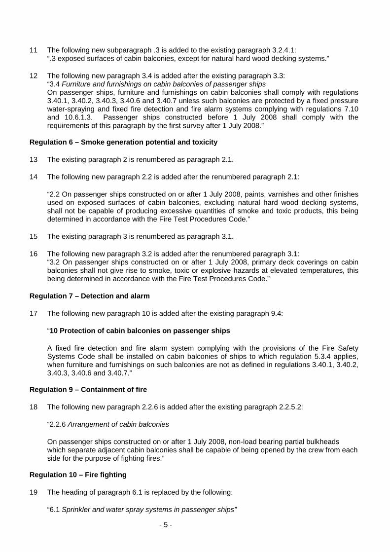
3.2.2.1 The fire tests should be conducted in a test apparatus consisting of a balcony mock-up inaccordance with figure 1. The balcony ceiling should be smooth to allow an unobstructed flow ofgases.
3.2.2.2 The mock-up should be constructed of nominally 12 mm thick non-combustible wallboardpanels. Plywood panels should be attached to the wall below the ventilation channel opening, and onthe back wall, covering at least 2 m horizontally, starting from the fan side corner. The panels shouldbe 2 m high and 3 to 4 mm thick. The ignition time of the panel should not be more than 35 s and theflame spread time at 350 mm position should not be more than 100 s as measured in accordance withthe FTP Code. Prior to the test, the plywood panels should be conditioned at 21 ± 2.8º C and 50 ± 10%relative humidity for at least 72 h.
3.2.2.3 The dimensions of the balconies should be in accordance with figure 1, or may be increased upto the maximum coverage area (length and width) to be protected by one nozzle.
3.2.2.4 A fan should be attached to the balcony mock-up, as indicated in figure 1. The fan shouldprovide an average air velocity of 5 ± 0.2 m/s measured as an average over several locations.Typically, sufficient dimensions of the fan are 0.8 m in diameter with a power of 5.5 kW.
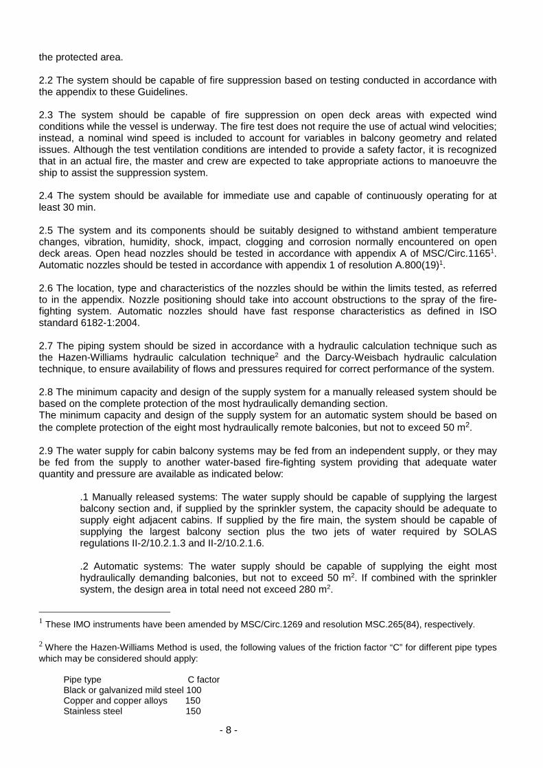
3.2.2.5 For ceiling nozzles, the velocity measurements should be done at nine locations; at the nozzleand around it on a circle of 0.5 m radius (figure 3(a)). For sidewall nozzles, the measurement should bedone in six locations, at the nozzle and around it on a half-circle of 0.5 m radius (figure 3(b)). In verticaldirection, the measurement should be done in the middle of the wind channel (25 cm from the ceiling).The intention is to distribute measurement locations over the region where the wind affects thesuppression medium flow.
3.2.3 Fire source
3.2.3.1 The fire source should consist of a wood crib, two simulated chairs and a table mock-up.
3.2.3.2 Each chair should be fitted with two 0.5 m by 0.8 m by 0.1 m polyether cushions.
The cushions should be made of non-fire retardant polyether and they should have a density ofapproximately 33 kg/m3. When tested according to standard ISO 5660-1 (ASTM E-1354), thepolyether foam should give results as given in the table below. Prior to the test, the cushions should beconditioned at 21 ± 2.8ºC and 50 ± 10% relative humidity for at least 72 h.The frame of the chairs should be of steel nominally 2 mm thick consisting of rectangular bottom andbackrest frames constructed of steel angles, channels or rectangular stock of at least 3 mm thickness.
- 12 -
The frame dimensions should be 0.5 m x 0.8 m (figure 2). The seat and backrest cushions should besupported on each frame by steel bars 20-30 mm wide x 0.80 m long located in the centre of theframes and welded to the edges. Steel plates should not be used to support the cushions.
The assembled frames should be supported by four legs 500 mm in height constructed of similar steelstock. The frames should be equipped with a metal wire net to support the cushions, and the backrestshould be tied in place, to keep from falling over during the test. The backrest should be placed on topof the seat cushion.
ISO 5660: Cone calorimeter test
Test conditions:
Irradiance 35 kW/m2
Horizontal positionSample thickness 50 mmNo frame retainer should be used
Test results Foam
Time to ignition (s) 2-63 min average HRR, q180 270 ± 5 0Minimum heat of combustion (MJ/kg) 25Total heat release (MJ/m2) 50 ± 1 2
3.2.3.3 A table should be constructed of a similar steel stock as the chairs. The table should have a 0.5m by 0.5 m metal frame, supported by four legs, 520 mm in height. A 0.5 m by 0.5 m table plate shouldbe fitted into the frame, made of 2 mm thick steel.
3.2.3.4 The two chairs should be placed in the fan side corner of the balcony, in such a way that thepolyether foam is 0.1 m from the plywood panel, according to figures 3 and 4, corners of the cushionstouching. The table should be placed in the corner, edges aligned with the ends of the chairs.
3.2.3.5 The wood crib should be dimensioned 0.3 m x 0.3 m x 0.15 m (high). The crib should consist offour alternate layers of four trade size nominal 38 mm x 38 mm kiln-dried spruce or fir lumber 0.3 mlong. The alternate layers of the lumber should be placed at right angles to theadjacent layers. The individual wood members in each layer should be evenly spaced along the lengthof the previous layer of wood members and stapled together. After the wood crib is assembled, itshould be conditioned at a temperature of 50 ± 5ºC for not less than 16 h. Following the conditioning,the moisture content of the crib should be measured at various locations with a probe-type moisturemeter. The moisture content of the crib should not exceed 5% prior to the fire test.
3.2.3.6 A square steel tray of area 0.1 m2 and height 0.1 m should be located under the table, so thatits corner is next to the point where chairs touch. The wood crib should be supported directly over thetray, edges aligned with the chair ends. The top of the wood crib should be 0.27 m above the floor level(figure 4).
3.2.3.7 For ignition, the tray should be filled with 1 l of water and 250 ml of commercial heptane.
3.2.4 Nozzle installation requirements
3.2.4.1 The tests with the given balcony dimensions are intended for a single nozzle protection.
The single nozzle has to be located symmetrically in the balcony, at the centreline in the positionrecommended by the manufacturer’s installation instructions, vertically at least 0.4 m above the loweredge of the wind channel. The two most conceivable locations are shown in figure 3.

- 13 -
3.2.4.2 If the nozzle is located closer to the fan side wall than at the centreline, the protection width ofthe nozzle will be less than 3 m, i.e. twice the tested distance between the nozzle and wall.If a larger than 3 m protection width is aimed at, a wider balcony should be constructed for the test.
3.2.4.3 The nozzle should be connected to a suitable water supply and arranged to operate at theminimum pressure specified by the manufacturer.
3.2.4.4 The tests should be repeated using two nozzle orientations, where applicable. At first, thelowest discharge density should be directed towards the cabin wall, and then, towards the fan sidewall.
3.2.5 Instrumentation
3.2.5.1 Thermocouples should be installed at four locations; two on the front edge of the balconyceiling, one 1 m and the other 2 m from the fan side wall, one of the back edge of the ceiling, 2 m fromthe fan side wall and one in the centre of the side wall opposite the fan. Thermocouples should beinstalled 30 mm from the ceiling.
3.2.5.2 System water pressure should be measured near the nozzle, and the system water flow rateshould be defined with suitable means for the system.
4 TEST METHOD
4.1 Test programme
4.1.1 Two tests should be done for each type of nozzle. One test with wind, and one without.
4.1.2 In the wind test, the fan should be started before ignition and operated continuously during thetest. The wind velocity should be measured when it has levelled, before ignition as defined inparagraph 3.2.2.5.
4.1.3 Automatic nozzles should be tested with the fusible element removed.
4.2 Ignition
The heptane in the tray should be ignited using a gas burner, long stick, match or equivalent.
4.3 Determination of pre-burn time
Prior to conducting the nozzle tests, the pre-burn time should be determined using materials from thesame lots to be used during system approval testing.
A minimum of two free-burn tests should be conducted with wind and two without wind. In each test,the flame attachment time to the wall should be recorded. The system activation time used during thenozzle tests with wind should be 30 s less than the average flame attachment time recorded in thefree-burn tests with wind. The system activation time used during the nozzle tests without wind shouldbe 30 s less than the average flame attachment time recorded in the free-burn tests without wind.
4.4 Test duration
The sprinkler system should be manually activated at the end of the pre-burn period. The test shouldbe conducted for 10 min after the sprinkler system is activated, and any remaining fire should bemanually extinguished.
4.5 Observations during the test
During the test, the following observations should be recorded:

- 14 -
.1 activation time of ventilation system (if applicable);
.2 time of ignition;
.3 activation time of the extinguishing system;
.4 time of ignition of the plywood panels (if any);
.5 time of extinguishment, if any; and
.6 time when the test is terminated.
5 ACCEPTANCE CRITERIA
5.1 For all tests, there should be no ignition of the plywood panels.
5.2 For the test without wind, 30 s after activation of the system, none of the thermocouples shouldshow temperatures exceeding 100ºC.
6 TEST REPORT
The test report should, as a minimum, include the following information:
.1 name and address of the test laboratory;
.2 date of issue and identification number of the test report;
.3 name and address of applicant;
.4 name and address of manufacturer or supplier of the nozzles;
.5 test method and purpose;
.6 nozzle identification;
.7 description of the tested nozzle;
.8 detailed drawings/photos of the test set-up;
.9 date of tests;
.10 measured nozzle pressure and flow characteristics;
.11 identification of the test equipment and used instruments;
.12 test results including observations and measurements made during and after thetest:
.1 maximum protected area per nozzle; and
.2 minimum operating pressures;
.13 deviations from the test method;
.14 conclusions; and
.15 date of the report and signature.

- 15 -
Figure 1: Balcony Mock-up

- 16 -
Figure 2: Chair frame
Figure 3: Fire scenario and measurements. Thermocouple locations (x) and wind measurementpositions (.) for (a) ceiling nozzle, (b) sidewall nozzle
Figure 4: Fire source

- 17 -

- 18 -
Annex 3INTERNATIONALMARITIME ORGANIZATION4 ALBERT EMBANKMENTLONDON SE1 7SR
Telephone: 020 7735 7611Fax: 020 7587 3210
E
Ref. T4/4.01IMO MSC.1/Circ.1274
3 June 2008
GUIDELINES FOR EVALUATION OF FIRE RISK OF EXTERNAL AREASON PASSENGER SHIPS
1 The Maritime Safety Committee, at its eighty-first session (10 to 19 May 2006), havingapproved draft amendments to SOLAS chapter II-2 related to the safety of cabin balconies inresponse to the fire on board the Star Princess, instructed the Sub-Committee on FireProtection to consider the safety of all external areas on passenger ships.
2 The Maritime Safety Committee, at its eighty-fourth session (7 to 16 May 2008), havingconsidered the draft Guidelines for evaluation of fire risk of external areas on passenger shipsprepared by the Sub-Committee on Fire Protection at its fifty-second session (14 to 18 January2008), approved the Guidelines for evaluation of fire risk of external areas on passenger ships,set out in the annex.
3 The annexed Guidelines consist of two parts:
.1 part 1: Design Guidelines for the evaluation of fire risk of external areas on new passengerships; and
.2 part 2: Simplified risk assessments method for external areas on passenger ships.
4 The annexed Guidelines are not intended to apply to external areas where cargoes and/orvehicles are stored.
5 Member Governments are invited to bring the annexed Guidelines to the attention of allParties concerned and, in particular, recommend that such Parties:
.1 use part 1 of the annexed Guidelines at the early stage of design of new passenger shipswhen determining the fire risk of external areas;
.2 conduct fire risk assessments in accordance with part 2 of the annexed Guidelineswhenever an external area on existing passenger ships is subject to change of use;and
.3 document fire risk assessments when conducted in accordance with part 2 of the annexedGuidelines within the Shipboard Safety Management System.
***

- 19 -
ANNEXPART 1
DESIGN GUIDELINES FOR THE EVALUATION OF FIRE RISK OF EXTERNAL AREAS ONPASSENGER SHIPS
1 FOREWORD
1.1 External areas have routinely been assumed to have little or no fire risk, and have notbeen required to comply with SOLAS chapter II-2 requirements applicable to interior spaces.
1.2 While this assumption may be accurate for general open deck areas, the continualevolution of new types of passenger amenities on open deck areas may be introducing levelsof fire risk that are not fully accounted for by the existing regulations.
1.3 These Guidelines are not intended to be applicable to cabin balconies as these areas shallcomply with the relevant requirements set out in resolution MSC.216(82).
1.4 These Guidelines have been developed to provide Administrations and designers with atool that may be used at the early stage of a design to assess the fire risk of external areas.
2 PERFORMANCE OF THE RISK ASSESSMENT
2.1 In considering fire protection for external areas, the fire risk of all external areas as well asthe impact of a fire in such areas should be evaluated3 taking into consideration such factorsas:
.1 use of the space (type of persons who have access to, any restriction of accessdue to security reasons);
.2 presence of combustible materials;
.3 presence of sources of ignition;
.4 ready accessibility for fire-fighting operations;
.5 ease of escape;
.6 proximity of ventilation intakes;
.7 proximity to essential systems;
.8 possibility of an external fire spreading to more than one internal fire zone; and
.9 relationship to escape routes, assembly stations and evacuation routes tosurvival craft.
3 EVALUATION OF THE RISK ASSESSMENT
3.1 For ships subject to part 1, the following paragraphs apply in lieu of paragraph 4.12 of part2.
3.2 Should the results of the risk assessment show that the fire risk of external areas, that arenormally categorized as category (4) or (5) in accordance with SOLAS regulation II-2/9.2.2.3.2.2 or category (10) in accordance with SOLAS regulation II-2/9.2.2.4.2.2, asappropriate, is such that actions should be taken to reduce it, the designers should consider:
3 Refer as appropriate to part 2 of these Guidelines.

- 20 -
.1 mitigation measures (including but not limited to those listed under 4 below),to be used in conjunction with a new risk assessment; or
.2 the area being constructed in accordance with the fire protection requirementsapplicable to internal spaces having same or similar fire risk.
3.3 Risk assessment and relevant evaluation resulting in additional fire protectionrequirements should be communicated to the Administration.
4 POSSIBLE MITIGATION MEASURES TO BE USED IN CONJUNCTION WITH THERISK ASSESSMENT
4.1 In relation to the results of the risk assessment, it is suggested that the followingmitigation measures should be applied, as appropriate:
.1 Ignitability and smoke and toxicity of primary deck coverings.Primary deck coverings located in positions where risk of ignition from belowis possible should comply with SOLAS regulations II-2/4.4.4 and II-2/6.3.
.2 Partial bulkheads.Partial bulkheads should be constructed of non-combustible materials inaccordance with SOLAS regulation II-2/5.3.1.2.1.
.3 Low flame-spread, smoke and toxicity characteristics of exposed surfaces.Surface materials such as deck finishes, carpets, decorations and veneersshould comply with parts 2 and 5 of annex 1 of the International Code forApplication of Fire Test Procedures (FTP Code).
.4 Fire detection and suppression.The area should be covered by a fire suppression and detection system.
.5 Lining of non-combustible material.Lining of bulkheads and ceilings should be of non-combustible material inaccordance with SOLAS regulation II-2/3.1.2.1.
.6 Furniture and furnishings.Furniture and furnishings should be of restricted fire risk in accordance withSOLAS regulation II-2/3.40.
.7 Structural fire protection.Additional structural fire protection should be provided at boundaries.
.8 Suspended material.Suspended materials should have quality of resistance to the propagation offlame in accordance with part 7 of annex 1 of the FTP Code.

- 21 -
PART 2
SIMPLIFIED RISK ASSESSMENT METHOD FOR EXTERNAL AREASON PASSENGER SHIPS
1 FOREWORD
1.1 SOLAS regulations II-2/9.2.2.3.2 and II-2/9.2.2.4.2.2 define open deck spaces as areashaving no significant fire risk, and for enclosed promenades that furnishings shall be restrictedto deck furniture. All external areas should be evaluated using this part 2 to determine if thereis an increased level of fire risk due to the presence of combustibles or ignition sources.
1.2 Measures to mitigate the risk should be implemented where appropriate.
2 APPROACH
2.1 The intent of this part is to present a methodology for performing simplified fire riskassessments of external areas. These Guidelines should not be used to evaluate changes topermanent structure such as bulkheads, decks or surface finishes, or to demonstratecompliance with SOLAS regulation II-2/17.
2.2 The simplified fire risk assessment consists of the following elements:.1 description of the intended use of the area;
.2 identification of the combustible materials;
.3 identification of the ignition sources;
.4 description of the means of escape from, and fire-fighting access to the area;
.5 description of the materials used for the construction of the decks andbulkheads that bound the area (if any);
.6 description of the fire-fighting systems and appliances in the area (if any);
.7 description of the fire detection and alarm systems in the area (if any);
.8 response procedures;
.9 identification of essential systems;
.10 identification of any ventilation intakes or equipment in or near the area;
.11 effects on other areas; and
.12 evaluation of the risk assessment.
3 PERSONNEL QUALIFICATIONS
3.1 The individuals performing the assessment should be ship’s designers, ship’s officers,company representatives or other persons suitably qualified. The individuals should be familiarwith the arrangement and construction of the ship, as well as the location and operation of fire-fighting and fire detection systems.
- 22 -
4 ASSESSMENT GUIDANCE
4.1 Description of the intended use of the areaThe intended use and arrangements of the area should be described in sufficient detail toallow an understanding of the equipment and operations to be conducted, including theexpected operation each day and any operational requirement or limitation. The location andarea to be occupied should be noted.
4.2 Identification of combustibles materials
4.2.1 An assessment should be made of the type and quantity of combustible materials andflammable liquids (except for liquors stored in bars for daily use) in the area as a result of theactivity should be prepared.
4.2.2 The potential fire load of any lifesaving equipment such as lifeboats, rescue boats andliferafts need not be included in the fire load assessment.
4.2.3 The assessment should also note if any combustible materials for other purposes areroutinely stored in or near the area being considered.
4.2.4 The location of any flammable oil tank vents that are in or adjacent to the area should benoted.
4.3 Identification of the ignition sources
Any sources of ignition in the area should be noted, along with a description of any safeguardsprovided. Ignition sources may include cigarettes, any open flames, cooking appliances andelectrical equipment.
4.4 Description of the means of escape from and fire-fighting access to the area
4.4.1 The expected number of crew and passengers likely to be present in the area should beestimated for day and night conditions.
4.4.2 The location of emergency equipment lockers should be considered with respect to thearea, along with the location of fire main valves and hydrants. Access routes for fire fightingshould be evaluated.
4.4.3 Consideration should also be given to the abilities of the persons likely to be in the areathat may need additional assistance to escape. (i.e. large number of children in play areas).
4.5 Description of the materials used for the construction of the decks and bulkheadsthat bound the areaThe vessel drawings should be consulted to determine the fire integrity of any bulkheads ordecks adjacent to the area. All combustible materials and finishes (including paints) in thepermanent construction of the ship should be noted, and their location with respect to the areaof consideration should be verified. Natural hard wood decking systems need not to beincluded in the assessment.
4.6 Description of the fire-fighting systems and appliances in the areaAvailability of fire-fighting systems and appliances in or near the area should be evaluated withrespect to the intended use and activities, the arrangement and the types of fire that wouldoccur in the area.
4.7 Description of the fire detection and alarm system in the area
4.7.1 The fire detection and alarm system in or near the area should be evaluated with respect
- 23 -
to the intended use and activities, the arrangement and the types of fire that would occur in thearea.
4.7.2 The number of crew in the area and the times they will be present should also be takeninto account. Information regarding the coverage of closed circuit television in the area shouldalso be noted.
4.8 Response proceduresThe fire-fighting procedures and instructions applicable to the area should be reviewed.
4.9 Identification of essential systemsProximity of systems essential for the safe operation of the ship (e.g., ships’ propulsion,steering, lifesaving, fire protection systems, internal and external communications) should beconsidered.
4.10 Identification of any ventilation intakes or equipment in or near the areaAny ventilation system equipment that might be affected by a fire in the area should beidentified. The distance to any air intakes or similar openings should be noted for the purposeof determining if smoke from a fire could be spread to other areas of the ship.
4.11 Effects on other areasEffects on assembly stations or evacuation routes and the possibility of the fire spread to morethan one fire zone should be considered.
4.12 Evaluation of the risk assessment
4.12.1 Based on the information provided in paragraphs 4.1 to 4.11 of this part, an evaluationshould be performed to determine the relative level of fire risk associated with the newintended use of the area, the potential fire damage to the ship, and whether the fire protectionis adequate for the expected level of risk.
4.12.2 If necessary, mitigation measures should be implemented to eliminate or reduce the fireto an acceptable level.