Embed Size (px)
Citation preview

BRITISH STANDARD BS EN 54-7:2001Incorporating Amendment No. 1
Fire detection and fire alarm systems —
Part 7: Smoke detectors — Point detectors using scattered light, transmitted light or ionization
The European Standard EN 54-7:2000, with the incorporation of amendment A1:2002, has the status of a British Standard
ICS 13.220.20; 13.320
���������������� ������������������������������� �������������Copyright British Standards Institution Provided by IHS under license with BSI
Not for ResaleNo reproduction or networking permitted without license from IHS
--`,``-`-`,,`,,`,`,,`---
BS EN 54-7:2001
This British Standard, having been prepared under the direction of the Health and Environment Sector Committee, was published under the authority of the Standards Committee and comes into effect on 15 March 2001
© BSI 11 March 2003
ISBN 0 580 37103 4
National foreword
This British Standard is the official English language version of EN 54-7:2000, including amendment A1:2002. It supersedes BS 5445-7:1984 and BS-5445-9:1984 which will be withdrawn on 06-2003. It is one of a series of standards for fire detection and fire alarm systems (see BS EN 54-1 for a full list of current and proposed standards).
The start and finish of text introduced or altered by amendment is indicated in the text by tags ��. Tags indicating changes to CEN text carry the number of the CEN amendment. For example, text altered by CEN amendment A1 is indicated by ��.�����
The UK participation in its preparation was entrusted by Technical Committee FSH/12, Fire detection and alarm systems, to Subcommittee FSH/12/2, Fire detectors, which has the responsibility to:
A list of organizations represented on this subcommittee can be obtained on request to its secretary.
Cross-references
The British Standards which implement international or European publications referred to in this document may be found in the BSI Catalogue under the section entitled “International Standards Correspondence Index”, or by using the “Search” facility of the BSI Electronic Catalogue or of British Standards Online.
This publication does not purport to include all the necessary provisions of a contract. Users are responsible for its correct application.
Compliance with a British Standard does not of itself confer immunity from legal obligations.
— aid enquirers to understand the text;
— present to the responsible European committee any enquiries on the interpretation, or proposals for change, and keep the UK interests informed;
— monitor related international and European developments and promulgate them in the UK.
Summary of pagesThis document comprises a front cover, an inside front cover, the EN title page, pages 2 to 61 and a back cover.
The BSI copyright date displayed in this document indicates when the document was last issued.
Amendments issued since publication
Amd. No. Date Comments
14339 11 March 2003 See national foreword
Copyright British Standards Institution Provided by IHS under license with BSI
Not for ResaleNo reproduction or networking permitted without license from IHS
--`,``-`-`,,`,,`,`,,`---

EUROPEAN STANDARD
NORME EUROPÉENNE
EUROPÄISCHE NORM
EN 54-7December 2000
+ A1June 2002
ICS 13.220.20 Supersedes EN 54-7:1982, EN 54-7:1982/A1:1988,EN 54-9:1982
English version
Fire detection and fire alarm systems — Part 7:Smoke detectors — Point detectors using scattered light,
transmitted light or ionization(includes amendment A1:2002)
Systèmes de détection et d’alarme incendie — Partie 7:Détecteurs de fumée — Détecteurs ponctuels fonctionnant
suivant le principe de la diffusion de la lumière, de latransmission de la lumière ou de l’ionisation
(inclut l'amendement A1:2002)
Brandmeldeanlagen — Teil 7: Rauchmelder —Punkförmige Melder nach dem Streulicht-, Durchlicht- oder
Ionisationprinzip(enthält Änderung A1:2002)
This European Standard was approved by CEN on 2 June 2000. Amendment A1 was approved by CEN on 5 April 2002.
CEN members are bound to comply with the CEN/CENELEC Internal Regulations which stipulate the conditions for giving this EuropeanStandard the status of a national standard without any alteration. Up-to-date lists and bibliographical references concerning such nationalstandards may be obtained on application to the Management Centre or to any CEN member.
This European Standard exists in three official versions (English, French, German). A version in any other language made by translationunder the responsibility of a CEN member into its own language and notified to the Management Centre has the same status as the officialversions.
CEN members are the national standards bodies of Austria, Belgium, Czech Republic, Denmark, Finland, France, Germany, Greece,Iceland, Ireland, Italy, Luxembourg, Netherlands, Norway, Portugal, Spain, Sweden, Switzerland and United Kingdom.
EUROPEAN COMMITTEE FOR STANDARDIZATIONC O M I T É E U R OP É E N D E N O R M A LI S A T I O NEUR O P Ä IS C HES KOM I TE E FÜR NOR M UNG
Management Centre: rue de Stassart, 36 B-1050 Brussels
© 2000 CEN All rights of exploitation in any form and by any means reservedworldwide for CEN national Members.
Ref. No. EN 54-7:2000 + A1:2002 E
Copyright British Standards Institution Provided by IHS under license with BSI
Not for ResaleNo reproduction or networking permitted without license from IHS
--`,``-`-`,,`,,`,`,,`---

Page 2EN 54-7:2000
© BSI 11 March 2003
Contents Page
Foreword ...........................................................................................................................................................41 Scope ....................................................................................................................................................52 Normative references ..........................................................................................................................53 Terms and definitions..........................................................................................................................64 Requirements .......................................................................................................................................64.1 Compliance...........................................................................................................................................64.2 Individual alarm indication..................................................................................................................64.3 Connection of ancillary devices.........................................................................................................64.4 Monitoring of detachable detectors...................................................................................................74.5 Manufacturer’s adjustments...............................................................................................................74.6 On-site adjustment of response behaviour.......................................................................................74.7 Protection against the ingress of foreign bodies.............................................................................74.8 Response to slowly developing fires.................................................................................................74.9 Marking .................................................................................................................................................84.10 Data .......................................................................................................................................................84.11 Additional requirements for software controlled detectors ............................................................85 Tests....................................................................................................................................................105.1 General................................................................................................................................................105.2 Repeatability.......................................................................................................................................135.3 Directional dependence ....................................................................................................................135.4 Reproducibility...................................................................................................................................145.5 Variation in supply parameters ........................................................................................................145.6 Air movement .....................................................................................................................................155.7 Dazzling ..............................................................................................................................................165.8 Dry heat (operational)........................................................................................................................165.9 Cold (operational) ..............................................................................................................................175.10 Damp heat, steady state (operational).............................................................................................185.11 Damp heat, steady state (endurance) ..............................................................................................195.12 Sulfur dioxide (SO2) corrosion (endurance)....................................................................................195.13 Shock (operational) ...........................................................................................................................205.14 Impact (operational)...........................................................................................................................215.15 Vibration, sinusoidal (operational)...................................................................................................225.16 Vibration, sinusoidal (endurance)....................................................................................................235.17 Electromagnetic compatibility (EMC), immunity tests (operational)............................................245.18 Fire sensitivity....................................................................................................................................25Annex A (normative) Smoke tunnel for response threshold value measurements............................27Annex B (normative) Test aerosol for response threshold value measurements ..............................28Annex C (normative) Smoke measuring instruments ............................................................................29Annex D (normative) Apparatus for dazzling test ..................................................................................34Annex E (informative) Apparatus for impact test .....................................................................................35Annex F (normative) Fire test room.........................................................................................................37Annex G (normative) Smouldering (pyrolysis) wood fire (TF2) ............................................................39Annex H (normative) Glowing smouldering cotton fire (TF3) ...............................................................41
Copyright British Standards Institution Provided by IHS under license with BSI
Not for ResaleNo reproduction or networking permitted without license from IHS
--`,``-`-`,,`,,`,`,,`---

Page 3EN 54-7:2000
© BSI 11 March 2003
Annex I (normative) Flaming plastics (polyurethane) fire (TF4)..........................................................43Annex J (normative) Flaming liquid (n-heptane) fire (TF5) ...................................................................45Annex K (informative) Information concerning the construction of the smoke tunnel........................47Annex L (informative) Information concerning the requirements for the response to slowly
developing fires .....................................................................................................49Annex M (informative) Information concerning the construction of the
measuring ionization chamber.............................................................................53Annex ZA (informative) Clauses of this European Standard addressing essential requirements or
other provisions of EU Directives........................................................................55Bibliography .................................................................................................................................61
Copyright British Standards Institution Provided by IHS under license with BSI
Not for ResaleNo reproduction or networking permitted without license from IHS
--`,``-`-`,,`,,`,`,,`---

Page 4EN 54-7:2000
© BSI 11 March 2003
ForewordThis European Standard has been prepared by Technical Committee CEN/TC 72, Fire detection andfire alarm systems, the Secretariat of which is held by BSI.
This European Standard replaces EN 54-7:1982, EN 54-7:1982/A1:1988, EN 54-9:1982.
This European Standard shall be given the status of a national standard, either by publication of an identicaltext or by endorsement, at the latest by June 2001, and conflicting national standards shall be withdrawn atthe latest by June 2003. For products which have complied with the relevant national standard before thedate of withdrawal (dow), as shown by the manufacturer or by a certification body, this previous standardmay continue to apply for production until June 2006.
This European Standard has been prepared under a mandate given to CEN by the European Commissionand the European Free Trade Association, and supports essential requirements of EU Directive(s).
According to the CEN/CENELEC Internal Regulations, the national standards organizations of the followingcountries are bound to implement this European Standard: Austria, Belgium, Czech Republic, Denmark,Finland, France, Germany, Greece, Iceland, Ireland, Italy, Luxembourg, Netherlands, Norway, Portugal,Spain, Sweden, Switzerland and the United Kingdom.
This standard has been prepared in cooperation with the CEA (Comité Européen des Assurances) and withEURALARM (Association of European Manufacturers of Fire and Intruder Alarm Systems).
The significant differences from EN 54-7:1982+A1:1988 include:� changes in the title of the EN 54 series and in the title of this part;� the incorporation of the full descriptions of the test fires for fire sensitivity into the standard;NOTE: These descriptions were previously given in part 9 of the standard.
� the introduction of requirements for the limitation of the effects of drift compensation on theresponse to slowly developing fires;
� the introduction of requirements for protection against ingress of foreign bodies;� changes in the environmental test procedures to use IEC tests where possible, to harmonize with
test procedures applied to other types of detectors and to include EMC immunity tests;� the requirement for an integral alarm indication.
EN 54-9:1982 and its amendments will all be withdrawn on publication of this revision.
Information on the relationship between this European Standard and other standards of the EN 54 series isgiven in annex A of EN 54-1:1996.
Foreword to amendment A1This document EN 54-7:2000/A1:2002) has been prepared by Technical Committee CEN/TC 72, Firedetection and fire alarm systems, the Secretariat of which is held by BSI.
This amendment to the European Standard EN 54-7:2000 shall be given the status of a national standard,either by publication of an identical text or by endorsement, at the latest by December 2002, and conflictingnational standards shall be withdrawn at the latest by June 2005.
This document has been prepared under a mandate given to CEN by the European Commission and theEuropean Free Trade Association, and supports essential requirements of EU Construction ProductsDirective (89/106/EEC)..
For relationship with the EU Construction Products Directive, see information annex ZA, which is an integralpart of this document.
According to the CEN/CENELEC Internal Regulations, the national standards organizations of the followingcountries are bound to implement this European Standard: Austria, Belgium, Czech Republic, Denmark,Finland, France, Germany, Greece, Iceland, Ireland, Italy, Luxembourg, Malta, Netherlands, Norway,Portugal, Spain, Sweden, Switzerland and the United Kingdom.
Copyright British Standards Institution Provided by IHS under license with BSI
Not for ResaleNo reproduction or networking permitted without license from IHS
--`,``-`-`,,`,,`,`,,`---

Page 5EN 54-7:2000
© BSI 11 March 2003
1 Scope
This European Standard specifies requirements, test methods and performance criteria for pointsmoke detectors that operate using scattered light, transmitted light or ionization, for use in fire detection andfire alarm systems for buildings (see EN 54-1:1996).
For other types of smoke detector, or smoke detectors working on different principles, this standard shouldonly be used for guidance. Smoke detectors with special characteristics and developed for specific risks arenot covered by this standard.
NOTE: Certain types of detector contain radioactive materials. The national requirements for radiation protectiondiffer from country to country and they are not specified in this standard.
2 Normative references
This European Standard incorporates, by dated or undated reference, provisions from other publications.These normative references are cited at the appropriate places in the text and the publications are listedhereafter. For dated references, subsequent amendments to or revisions of any of these publications applyto this European Standard only when incorporated in it by amendment or revision. For undated referencesthe latest edition of the publication referred to applies.
ISO/IECPublication
Year Title EN/HDPublication
Year
- - Fire detection and fire alarm systems —Part 1: Introduction.
EN 54-1 1996
- - Alarm Systems — Part 4: Electromagneticcompatibility — Product family standard: Immunityrequirements for components of fire, intruder andsocial alarm systems, +A1:1998.
EN 50130-4 1995
IEC 60068-1 1988 Environmental testing — Part 1: General andguidance, +A1:1992.
EN 60068-1 1994
IEC 60068-2-1 1990 Environmental testing — Part 2: Tests — Tests A:Cold, +A1:1993, A2:1994.
EN 60068-2-1 1993
IEC 60068-2-3 1969 Basic environmental testing procedures —Part 2: Tests — Test Ca: Damp heat, steady state,+A1:1984.
HD 323.2.3 S2 1987
Copyright British Standards Institution Provided by IHS under license with BSI
Not for ResaleNo reproduction or networking permitted without license from IHS
--`,``-`-`,,`,,`,`,,`---

Page 6EN 54-7:2000
© BSI 11 March 2003
ISO/IECPublication
Year Title EN/HDPublication
Year
IEC 60068-2-6 1995 Environmental testing — Part 2: Tests — Test Fc.Vibration (sinusoidal), +Corr.:1995.
EN 60068-2-6 1995
IEC 60068-2-27 1987 Basic environmental testing procedures —Part 2: Tests — Test Ea & Guidance: Shock.
EN 60068-2-27 1993
IEC 60068-2-42 1982 Basic environmental testing procedures —Part 2: Tests — Test Kc: Sulfur dioxide test forcontacts and connections.
- -
IEC 60068-2-56 1988 Environmental testing — Part 2: Tests — Test Cb:Damp heat steady state, primarily for equipment.
HD 323.2.56 S1 1990
ISO 209-1 1989 Wrought aluminium and aluminium alloys —Chemical composition and forms of products —-Part 1: Chemical composition.
- -
3 Terms and definitions
For the purposes of this standard, the following term and definition and those given in EN 54-1:1996 apply:
3.1response threshold valueaerosol density in the proximity of the specimen at the moment that it generates an alarm signal, when testedas described in 5.1.5
NOTE: The response threshold value may depend on signal processing in the detector and in the control andindicating equipment.
4 Requirements
4.1 Compliance
In order to comply with this standard the detector shall meet the requirements of this clause, which shall beverified by visual inspection or engineering assessment, shall be tested as described in clause 5 and shallmeet the requirements of the tests.
4.2 Individual alarm indication
Each detector shall be provided with an integral red visual indicator, by which the individual detector, whichreleased an alarm, can be identified until the alarm condition is reset. Where other conditions of the detectorcan be visually indicated, they shall be clearly distinguishable from the alarm indication, except when thedetector is switched into a service mode. For detachable detectors the indicator may be integral with thebase or the detector head. The visual indicator shall be visible from a distance of 6 m directly below thedetector, in an ambient light intensity up to 500 lux.
4.3 Connection of ancillary devices
Where the detector provides for connections to ancillary devices (e.g. remote indicators, control relays),open- or short-circuit failures of these connections shall not prevent the correct operation of the detector.
Copyright British Standards Institution Provided by IHS under license with BSI
Not for ResaleNo reproduction or networking permitted without license from IHS
--`,``-`-`,,`,,`,`,,`---

Page 7EN 54-7:2000
© BSI 11 March 2003
4.4 Monitoring of detachable detectors
For detachable detectors, a means shall be provided for a remote monitoring system (e.g. the control andindicating equipment) to detect the removal of the head from the base, in order to give a fault signal.
4.5 Manufacturer’s adjustments
It shall not be possible to change the manufacturer’s settings except by special means (e.g. the use of aspecial code or tool) or by breaking or removing a seal.
4.6 On-site adjustment of response behaviour
If there is provision for on-site adjustment of the response behaviour of the detector then:
1) for each setting at which the manufacturer claims compliance with this standard, the detectorshall comply with the requirements of this standard, and access to the adjustment means shallonly be possible by the use of a code or special tool or by removing the detector from its base ormounting;
2) any setting(s) at which the manufacturer does not claim compliance with this standard shall onlybe accessible by the use of a code or special tool, and it shall be clearly marked on the detectoror in the associated data, that if these setting(s) are used, the detector does not comply with thestandard.
NOTE: These adjustments may be carried out at the detector or at the control and indicating equipment.
4.7 Protection against the ingress of foreign bodies
The detector shall be so designed that a sphere of diameter (1,3 ± 0,05) mm cannot pass into the sensorchamber(s).
NOTE: This requirement is intended to restrict the access of insects into the sensitive parts of the detector. It isknown that this requirement is not sufficient to prevent the access of all insects, however it is considered thatextreme restrictions on the size of access holes may introduce the danger of clogging by dust etc. It maytherefore be necessary to take other precautions against false alarms due to the entry of small insects.
4.8 Response to slowly developing fires
The provision of “drift compensation” (e.g. to compensate for sensor drift due to the build-up of dirt in thedetector), shall not lead to a significant reduction in the detector’s sensitivity to slowly developing fires.
Since it is not practical to make tests with very slow increases in smoke density, an assessment of thedetector’s response to slow increases in smoke density shall be made by analysis of the circuit/software,and/or physical tests and simulations.
The detector shall be deemed to meet the requirements of this clause if this assessment shows that:
a) for any rate of increase in smoke density R, which is greater than A/4 per hour (where A is thedetector’s initial uncompensated response threshold value), the time for the detector to give analarm does not exceed 1,6 � A/R by more than 100 s; and
b) the range of compensation is limited such that, throughout this range, the compensation does notcause the response threshold value of the detector to exceed its initial value by a factorgreater than 1,6.
NOTE: Further information about the assessment of these requirements is given in annex L.
Copyright British Standards Institution Provided by IHS under license with BSI
Not for ResaleNo reproduction or networking permitted without license from IHS
--`,``-`-`,,`,,`,`,,`---

Page 8EN 54-7:2000
© BSI 11 March 2003
4.9 Marking
Each detector shall be clearly marked with the following information:
a) the number of this standard (i.e. EN 54-7);
b) the name or trademark of the manufacturer or supplier;
c) the model designation (type or number);
d) the wiring terminal designations;
e) some mark(s) or code(s) (e.g. serial number or batch code), by which the manufacturer canidentify, at least, the date or batch and place of manufacture, and the version number(s) of anysoftware contained within the detector.
For detachable detectors, the detector head shall be marked with a), b), c) and e), and the base shall bemarked with at least c) (i.e. its own model designation) and d).
Where any marking on the device uses symbols or abbreviations not in common use then these shall beexplained in the data supplied with the device.
The marking shall be visible during installation of the detector and shall be accessible during maintenance.
The markings shall not be placed on screws or other easily removable parts.
4.10 Data
Detectors shall either be supplied with sufficient technical, installation and maintenance data to enable theircorrect installation and operation1) or, if all of these data are not supplied with each detector, reference to theappropriate data sheet shall be given on, or with, each detector.
NOTE: Additional information may be required by organizations certifying that detectors produced by amanufacturer conform to the requirements of this standard.
4.11 Additional requirements for software controlled detectors
4.11.1 General
For detectors which rely on software control in order to fulfil the requirements of this standard, therequirements of 4.11.2, 4.11.3 and 4.11.4 shall be met.
4.11.2 Software documentation
4.11.2.1 The manufacturer shall submit documentation which gives an overview of the software design.This documentation shall be in sufficient detail for the design to be inspected for compliance with thisstandard and shall include at least the following:
a) a functional description of the main program flow (e.g. as a flow diagram or structogram)including:
1) a brief description of the modules and the functions that they perform;
1) To enable correct operation of the detectors, these data should describe the requirements for the correct processing of the signals fromthe detector. This may be in the form of a full technical specification of these signals, a reference to the appropriate signalling protocol or areference to suitable types of control and indicating equipment etc.
Copyright British Standards Institution Provided by IHS under license with BSI
Not for ResaleNo reproduction or networking permitted without license from IHS
--`,``-`-`,,`,,`,`,,`---

Page 9EN 54-7:2000
© BSI 11 March 2003
2) the way in which the modules interact;
3) the overall hierarchy of the program;
4) the way in which the software interacts with the hardware of the detector;
5) the way in which the modules are called, including any interrupt processing.
b) a description of which areas of memory are used for the various purposes (e.g. the program,site specific data and running data);
c) a designation, by which the software and its version can be uniquely identified.
4.11.2.2 The manufacturer shall have available detailed design documentation, which only needs to beprovided if required by the testing authority. It shall comprise at least the following:
a) an overview of the whole system configuration, including all software and hardware components;
b) a description of each module of the program, containing at least:
1) the name of the module;
2) a description of the tasks performed;
3) a description of the interfaces, including the type of data transfer, the valid data range and thechecking for valid data.
c) full source code listings, as hard copy or in machine-readable form (e.g. ASCII-code), including allglobal and local variables, constants and labels used, and sufficient comment for the programflow to be recognized;
d) details of any software tools used in the design and implementation phase (e.g. CASE-tools,compilers).
4.11.3 Software design
In order to ensure the reliability of the detector, the following requirements for software design shall apply:
a) the software shall have a modular structure;
b) the design of the interfaces for manually and automatically generated data shall not permitinvalid data to cause error in the program operation;
c) the software shall be designed to avoid the occurrence of deadlock of the program flow.
4.11.4 The storage of programs and data
The program necessary to comply with this standard and any pre-set data, such as manufacturer’s settings,shall be held in non-volatile memory. Writing to areas of memory containing this program and data shall onlybe possible by the use of some special tool or code and shall not be possible during normal operation of thedetector.
Site-specific data shall be held in memory which will retain data for at least two weeks without external powerto the detector, unless provision is made for the automatic renewal of such data, following loss of power,within 1 h of power being restored.
Copyright British Standards Institution Provided by IHS under license with BSI
Not for ResaleNo reproduction or networking permitted without license from IHS
--`,``-`-`,,`,,`,`,,`---

Page 10EN 54-7:2000
© BSI 11 March 2003
5 Tests
5.1 General
5.1.1 Atmospheric conditions for tests
Unless otherwise stated in a test procedure, the testing shall be carried out after the test specimen has beenallowed to stabilize in the standard atmospheric conditions for testing as described inIEC 60068-1:1988+A1:1992 as follows:
a) temperature: (15 to 35) °C;
b) relative humidity: (25 to 75) %;
c) air pressure: (86 to 106) kPa.
NOTE: If variations in these parameters have a significant effect on a measurement, then such variations shouldbe kept to a minimum during a series of measurements carried out as part of one test on one specimen.
5.1.2 Operating conditions for tests
If a test method requires a specimen to be operational, then the specimen shall be connected to suitablesupply and monitoring equipment with characteristics as required by the manufacturer’s data. Unlessotherwise specified in the test method, the supply parameters applied to the specimen shall be set within themanufacturer’s specified range(s) and shall remain substantially constant throughout the tests. The valuechosen for each parameter shall normally be the nominal value, or the mean of the specified range. If atest procedure requires a specimen to be monitored to detect any alarm or fault signals, then connectionsshall be made to any necessary ancillary devices (e.g. through wiring to an end-of-line device forconventional detectors) to allow a fault signal to be recognized.
NOTE: The details of the supply and monitoring equipment and the alarm criteria used should be given in thetest report.
5.1.3 Mounting arrangements
The specimen shall be mounted by its normal means of attachment in accordance with the manufacturer’sinstructions. If these instructions describe more than one method of mounting then the method considered tobe most unfavorable shall be chosen for each test.
5.1.4 Tolerances
Unless otherwise stated, the tolerances for the environmental test parameters shall be as given in the basicreference standards for the test (e.g. the relevant part of IEC 60068).
If a requirement or test procedure does not specify a tolerance or deviation limits, then deviation limits of±5 % shall be applied.
5.1.5 Measurement of response threshold value
The specimen for which the response threshold value is to be measured shall be installed in thesmoke tunnel, described in annex A, in its normal operating position, by its normal means of attachment. Theorientation of the specimen relative to the direction of airflow shall be the least sensitive orientation, asdetermined in the directional dependence test, unless otherwise specified in the test procedure.
Before commencing each measurement the smoke tunnel shall be purged to ensure that the tunnel and thespecimen are free from the test aerosol.
The air velocity in the proximity of the specimen shall be (0,2 ± 0,04) m s-1 during the measurement, unlessotherwise specified in the test procedure.
Copyright British Standards Institution Provided by IHS under license with BSI
Not for ResaleNo reproduction or networking permitted without license from IHS
--`,``-`-`,,`,,`,`,,`---

Page 11EN 54-7:2000
© BSI 11 March 2003
Unless otherwise specified in the test procedure, the air temperature in the tunnel shall be (23 ± 5) °C andshall not vary by more than 5 K for all the measurements on a particular detector type.
The specimen shall be connected to its supply and monitoring equipment as described in 5.1.2, and shall beallowed to stabilize for a period of at least 15 min, unless otherwise specified by the manufacturer.
The test aerosol, as described in annex B, shall be introduced into the tunnel such that the rate of increaseof aerosol density is as follows:
11- minm dB0,10,015 �
��
��
t
m
for detectors using scattered or transmitted light; or
1-min0,30,05 ��
��
t
y
for detectors using ionization.
NOTE 1: These ranges are intended to allow the selection of a convenient rate, depending upon the detector’ssensitivity, to get a response in a reasonable time.
NOTE 2: The equations for m and y are given in annex C.
The rate of increase in aerosol density shall be similar for all measurements on a particular detector type.
The aerosol density at the moment that the specimen gives an alarm shall be recorded as m (dB m-1) fordetectors using scattered or transmitted light, or as y for detectors using ionization (see annex C). This shallbe taken as the response threshold value.
5.1.6 Provision for tests
The following shall be provided for testing compliance with this standard:
a) for detachable detectors: twenty detector heads and bases;
for non-detachable detectors: twenty specimens;
b) the data required in 4.10.
NOTE 1: Detachable detectors comprise at least two parts; a base (socket) and a head (body). If the specimensare detachable detectors, then the two, or more, parts together are regarded as a complete detector.
The specimens submitted shall be representative of the manufacturer’s normal production with regard totheir construction and calibration.
NOTE 2: This implies that the mean response threshold value of the twenty specimens found in thereproducibility test should also represent the production mean, and that the limits specified in thereproducibility test should also be applicable to the manufacturer’s production.
Copyright British Standards Institution Provided by IHS under license with BSI
Not for ResaleNo reproduction or networking permitted without license from IHS
--`,``-`-`,,`,,`,`,,`---

Page 12EN 54-7:2000
© BSI 11 March 2003
5.1.7 Test schedule
The specimens shall be tested according to the following test schedule (see Table 1). After thereproducibility test, the four least sensitive specimens (i.e. those with the highest response thresholds) shallbe numbered 17 to 20, and the others shall be numbered 1 to 16 arbitrarily.
Table 1 — Test schedule
Test Clause Specimen No(s)Repeatability 5.2 one chosen arbitrarilyDirectional dependence 5.3 one chosen arbitrarilyReproducibility 5.4 all specimensVariation in supply parameters 5.5 1Air movement 5.6 2Dazzling1) 5.7 3Dry heat (operational) 5.8 4Cold (operational) 5.9 5Damp heat, steady state (operational) 5.10 6Damp heat, steady state (endurance) 5.11 7Sulfur dioxide (SO2) corrosion (endurance) 5.12 8Shock (operational) 5.13 9Impact (operational) 5.14 10Vibration, sinusoidal (operational) 5.15 11Vibration, sinusoidal (endurance) 5.16 11Electrostatic discharge (operational) 5.17 122)
Radiated electromagnetic fields (operational) 5.17 132)
Conducted disturbances induced by electromagnetic fields(operational)
5.17 142)
Fast transient bursts (operational) 5.17 152)
Slow high energy voltage surge (operational) 5.17 162)
Fire sensitivity 5.18 17, 18, 19 and 201) This test only applies to detectors using scattered or transmitted light.2) In the interests of test economy, it is permitted to use the same specimen for more than one EMC test. In that case,intermediate functional test(s) on the specimen(s) used for more than one test may be deleted, and the functional testconducted at the end of the sequence of tests. However, it should be noted that in the event of a failure, it may not bepossible to identify which test exposure caused the failure (see clause 4 of EN 50130-4:1995+A1:1998).
Copyright British Standards Institution Provided by IHS under license with BSI
Not for ResaleNo reproduction or networking permitted without license from IHS
--`,``-`-`,,`,,`,`,,`---
Page 13EN 54-7:2000
© BSI 11 March 2003
5.2 Repeatability
5.2.1 Object
To show that the detector has stable behaviour with respect to its sensitivity even after a number of alarmconditions.
5.2.2 Test procedure
The response threshold value of the specimen to be tested shall be measured as described in 5.1.5six times.
The specimen’s orientation relative to the direction of air flow is arbitrary, but it shall be the same for all sixmeasurements.
The maximum response threshold value shall be designated ymax or mmax, the minimum value shall bedesignated ymin or mmin.
5.2.3 Requirements
The ratio of the response threshold values ymax : ymin or mmax : mmin shall not be greater than 1,6.
The lower response threshold value ymin shall be not less than 0,2, or mmin shall not be less than 0,05 dB m-1.
5.3 Directional dependence
5.3.1 Object
To confirm that the sensitivity of the detector is not unduly dependent on the direction of airflow around thedetector.
5.3.2 Test procedure
The response threshold value of the specimen to be tested shall be measured eight times as described in5.1.5, the specimen being rotated 45° about its vertical axis between each measurement, so that themeasurements are taken for eight different orientations relative to the direction of air flow.
The maximum response threshold value shall be designated ymax or mmax, the minimum value shall bedesignated ymin or mmin.
The orientations for which the maximum and minimum response threshold values were measured shall benoted.
In the following tests the orientation for which the maximum response threshold was measured is referred toas the least sensitive orientation, and the orientation for which the minimum response threshold wasmeasured is referred to as the most sensitive orientation.
5.3.3 Requirements
The ratio of the response threshold values ymax : ymin or mmax : mmin shall not be greater than 1,6.
The lower response threshold value ymin shall not be less than 0,2, or mmin shall not be less than 0,05 dB m-1.
Copyright British Standards Institution Provided by IHS under license with BSI
Not for ResaleNo reproduction or networking permitted without license from IHS
--`,``-`-`,,`,,`,`,,`---

Page 14EN 54-7:2000
© BSI 11 March 2003
5.4 Reproducibility
5.4.1 Object
To show that the sensitivity of the detector does not vary unduly from specimen to specimen and to establishresponse threshold value data for comparison with the response threshold values measured after theenvironmental tests.
5.4.2 Test procedure
The response threshold value of each of the test specimens shall be measured as described in 5.1.5.
The mean of these response threshold values shall be calculated and shall be designated y or m .
The maximum response threshold value shall be designated ymax or mmax; the minimum value shall bedesignated ymin or mmin.
5.4.3 Requirements
The ratio of the response threshold values ymax : y or mmax : m shall not be greater than 1,33, and the ratioof the response threshold values y : ymin or m : mmin shall not be greater than 1,5.
The lower response threshold value ymin shall not be less than 0,2, or mmin shall not be less than 0,05 dB m-1.
5.5 Variation in supply parameters
5.5.1 Object
To show that, within the specified range(s) of the supply parameters (e.g. voltage), the sensitivity of thedetector is not unduly dependent on these parameters.
5.5.2 Test procedure
The response threshold value of the specimen shall be measured as described in 5.1.5, at the upper andlower limits of the supply parameter (e.g. voltage) range(s) specified by the manufacturer.
The maximum response threshold value shall be designated ymax or mmax and the minimum value shall bedesignated ymin or mmin.
NOTE: For conventional detectors the supply parameter is the dc voltage applied to the detector. For othertypes of detector (e.g. analogue addressable) signal levels and timing may need to be considered. If necessary,the manufacturer may be requested to provide suitable supply equipment to allow the supply parameters to bechanged as required.
5.5.3 Requirements
The ratio of the response threshold values ymax : ymin or mmax : mmin shall not be greater than 1,6.
The lower response threshold value ymin shall not be less than 0,2, or mmin shall not be less than 0,05 dB m-1.
Copyright British Standards Institution Provided by IHS under license with BSI
Not for ResaleNo reproduction or networking permitted without license from IHS
--`,``-`-`,,`,,`,`,,`---

Page 15EN 54-7:2000
© BSI 11 March 2003
5.6 Air movement
5.6.1 Object
To show that the sensitivity of the detector is not unduly affected by the rate of the air flow, and that it is notunduly prone to false alarms in draughts or in short gusts.
5.6.2 Test Procedure
The response threshold value of the specimen to be tested shall be measured as described in 5.1.5 in themost and least sensitive orientations, and shall be appropriately designated y(0,2)max and y(0,2)min or m(0,2)maxand m(0,2)min.
These measurements shall then be repeated but with an air velocity, in the proximity of the detector, of(1 ± 0,2) m s-1. The response threshold values in these tests shall be designated y(1,0)max and y(1,0)min orm(1,0)max and m(1,0)min.
Additionally, for detectors using ionization, the specimen to be tested shall be subjected, in its most sensitiveorientation, to an aerosol-free air flow at a velocity of (5 ± 0,5) m s-1 for a period of not less than 5 min andnot more that 7 min, and then at least 10 min later to a gust at a velocity of (10 ± 1) m s-1 for a period of notless than 2 s and not more than 4 s. The specimen shall be monitored during the exposure to aerosol-free airto detect any alarm or fault signals.
NOTE: These exposures can be generated by plunging the specimen to be tested into an airflow with theappropriate velocity for the required time.
5.6.3 Requirements
For detectors using ionization the following shall apply:
1,60,625min(1,0)max(1,0)
min(0,2)max(0,2)�
�
�
�
yy
yy
and the detector shall emit neither a fault signal nor an alarm signal during the test with aerosol-free air.
For detectors using scattered or transmitted light the following shall apply:
1,60,625min(1,0)max(1,0)
min(0,2)max(0,2)�
�
�
�
mm
mm
Copyright British Standards Institution Provided by IHS under license with BSI
Not for ResaleNo reproduction or networking permitted without license from IHS
--`,``-`-`,,`,,`,`,,`---

Page 16EN 54-7:2000
© BSI 11 March 2003
5.7 Dazzling
5.7.1 Object
To show that the sensitivity of the detector is not unduly influenced by the close proximity of artificial lightsources. This test is only applied to detectors using scattered light or transmitted light, as detectors usingionization are considered unlikely to be influenced.
5.7.2 Test procedure
The dazzling apparatus, described in annex D, is installed in the smoke tunnel described in annex A.The specimen is installed in the dazzling apparatus in the least sensitive orientation and connected to itssupply and monitoring equipment. The following test procedure is then applied:
The response threshold value is measured as described in 5.1.5.
The four lamps are switched simultaneously ON for 10 s and then OFF for 10 s, ten times.
The four lamps are then switched ON again and after at least 1 min the response threshold value ismeasured, as described in 5.1.5, with the lamps ON.
The four lamps are then switched OFF.
The above procedure is then repeated but with the detector rotated 90° in one direction (either direction canbe chosen), from the least sensitive orientation.
For each orientation, the maximum response threshold value shall be designated mmax and the minimumresponse threshold value shall be designated mmin.
5.7.3 Requirements
During the periods when the lamps are being switched ON and OFF, and when the lamps are ON before theresponse threshold value is measured, the specimen shall emit neither an alarm nor a fault signal.
For each orientation, the ratio of the response thresholds mmax : mmin shall not be greater than 1,6.
5.8 Dry heat (operational)
5.8.1 Object
To demonstrate the ability of the detector to function correctly at high ambient temperatures appropriate tothe anticipated service environment.
5.8.2 Test procedure
The specimen to be tested shall be installed in the smoke tunnel described in annex A in its least sensitiveorientation, with an initial air temperature of (23 ± 5) °C, and shall be connected to its supply and monitoringequipment.
The air temperature in the smoke tunnel shall then be increased to (55 ± 2) °C at a rate not exceeding1 K min-1, and maintained at this temperature for 2 h.
The response threshold value shall then be measured as described in 5.1.5 but with the temperature at(55 ± 2) °C.
The greater of the response threshold values measured in this test and that measured for the samespecimen in the reproducibility test, shall be designated ymax or mmax, and the lesser shall be designatedymin or mmin.
Copyright British Standards Institution Provided by IHS under license with BSI
Not for ResaleNo reproduction or networking permitted without license from IHS
--`,``-`-`,,`,,`,`,,`---

Page 17EN 54-7:2000
© BSI 11 March 2003
5.8.3 Requirements
No alarm or fault signal shall be given during the period that the temperature is increasing to the conditioningtemperature, or during the conditioning period, until the response threshold value is measured.
The ratio of the response threshold values ymax : ymin or mmax : mmin shall not be greater than 1,6.
5.9 Cold (operational)
5.9.1 Object
To demonstrate the ability of the detector to function correctly at low ambient temperatures appropriate to theanticipated service environment.
5.9.2 Test procedure
5.9.2.1 Reference
The test apparatus and procedure shall be as described in IEC 60068-2-1:1990+A1:1993+A2:1994 Test Ab,and as described below.
5.9.2.2 State of the specimen during conditioning
The specimen shall be mounted as described in 5.1.3 and shall be connected to supply and monitoringequipment as described in 5.1.2.
5.9.2.3 Conditioning
The following conditioning shall be applied:
Temperature: (-10 ± 3) °C.Duration: 16 h.
NOTE: Test Ab specifies rates of change of temperature of � 1 K min-1 for the transitions to and from theconditioning temperature.
5.9.2.4 Measurements during conditioning
The specimen shall be monitored during the conditioning period to detect any alarm or fault signals.
5.9.2.5 Final measurements
After a recovery period of at least 1 h at the standard laboratory conditions, the response threshold valueshall be measured as described in 5.1.5.
The greater of the response threshold values measured in this test and that measured for the samespecimen in the reproducibility test, shall be designated ymax or mmax, and the lesser shall be designatedymin or mmin.
5.9.3 Requirements
No alarm or fault signal shall be given during the transition to the conditioning temperature or during theperiod at the conditioning temperature.
The ratio of the response threshold values ymax : ymin or mmax : mmin shall not be greater than 1,6.
Copyright British Standards Institution Provided by IHS under license with BSI
Not for ResaleNo reproduction or networking permitted without license from IHS
--`,``-`-`,,`,,`,`,,`---

Page 18EN 54-7:2000
© BSI 11 March 2003
5.10 Damp heat, steady state (operational)
5.10.1 Object
To demonstrate the ability of the detector to function correctly at high relative humidity (withoutcondensation), which may occur for short periods in the anticipated service environment.
5.10.2 Test procedure
5.10.2.1 Reference
The test apparatus and procedure shall be as described in IEC 60068-2-56:1988 Test Cb and as describedbelow.
5.10.2.2 State of the specimen during conditioning
The specimen shall be mounted as described in 5.1.3 and shall be connected to supply and monitoringequipment as described in 5.1.2.
5.10.2.3 Conditioning
The following conditioning shall be applied:
Temperature: (40 ± 2) °C.Relative Humidity: (93 ± 3) %.Duration: 4 days.
5.10.2.4 Measurements during conditioning
The specimen shall be monitored during the conditioning period to detect any alarm or fault signals.
5.10.2.5 Final measurements
After a recovery period of at least 1 h at the standard laboratory conditions, the response threshold valueshall be measured as described in 5.1.5.
The greater of the response threshold value measured in this test and that measured for the same specimenin the reproducibility test, shall be designated ymax or mmax, and the lesser shall be designated ymin or mmin.
5.10.3 Requirements
No alarm or fault signal shall be given during the conditioning.
The ratio of the response threshold values ymax : ymin or mmax : mmin shall not be greater than 1,6.
Copyright British Standards Institution Provided by IHS under license with BSI
Not for ResaleNo reproduction or networking permitted without license from IHS
--`,``-`-`,,`,,`,`,,`---

Page 19EN 54-7:2000
© BSI 11 March 2003
5.11 Damp heat, steady state (endurance)
5.11.1 Object
To demonstrate the ability of the detector to withstand the long-term effects of humidity in the serviceenvironment (e.g. changes in electrical properties of materials, chemical reactions involving moisture,galvanic corrosion, etc.).
5.11.2 Test procedure
5.11.2.1 Reference
The test apparatus and procedure shall be as described in IEC 60068-2-56:1988 Test Cb orIEC 60068-2-3:1969+A1:1984 Test Ca, and as described below.
5.11.2.2 State of the specimen during conditioning
The specimen shall be mounted as described in 5.1.3 but shall not be supplied with power during theconditioning.
5.11.2.3 Conditioning
The following conditioning shall be applied:
Temperature: (40 ± 2) °C.Relative Humidity: (93 ± 3) %.Duration: 21 days.
5.11.2.4 Final measurements
After a recovery period of at least 1 h in standard laboratory conditions, the response threshold value shallbe measured as described in 5.1.5.
The greater of the response threshold value measured in this test and that measured for the same specimenin the reproducibility test, shall be designated ymax or mmax, and the lesser shall be designated ymin or mmin.
5.11.3 Requirements
No fault signal attributable to the endurance conditioning shall be given on reconnection of the specimen.
The ratio of the response threshold values ymax : ymin or mmax : mmin shall not be greater than 1,6.
5.12 Sulfur dioxide (SO2) corrosion (endurance)
5.12.1 Object
To demonstrate the ability of the detector to withstand the corrosive effects of sulfur dioxide as anatmospheric pollutant.
5.12.2 Test procedure
5.12.2.1 Reference
The test apparatus and procedure shall be as described in IEC 60068-2-42:1982 Test Kc, except that theconditioning shall be as described below.
Copyright British Standards Institution Provided by IHS under license with BSI
Not for ResaleNo reproduction or networking permitted without license from IHS
--`,``-`-`,,`,,`,`,,`---

Page 20EN 54-7:2000
© BSI 11 March 2003
5.12.2.2 State of the specimen during conditioning
The specimen shall be mounted as described in 5.1.3. It shall not be supplied with power during theconditioning, but it shall have untinned copper wires, of the appropriate diameter, connected to sufficientterminals, to allow the final measurement to be made without making further connections to the specimen.
5.12.2.3 Conditioning
The following conditioning shall be applied:
Temperature: (25 ± 2) °C.Relative humidity: (93 ± 3) %.SO2 concentration: (25 ± 5) ppm (by volume).Duration: 21 days.
5.12.2.4 Final measurements
Immediately after the conditioning, the specimen shall be subjected to a drying period of 16 h at (40 ± 2) °C,� 50% RH, followed by a recovery period of at least 1 h at the standard laboratory conditions. After this, theresponse threshold value shall be measured as described in 5.1.5.
The greater of the response threshold value measured in this test and that measured for the same specimenin the reproducibility test, shall be designated ymax or mmax, and the lesser shall be designated ymin or mmin.
5.12.3 Requirements
No fault signal attributable to the endurance conditioning shall be given on reconnection of the specimen.
The ratio of the response threshold values ymax : ymin or mmax : mmin shall not be greater than 1,6.
5.13 Shock (operational)
5.13.1 Object
To demonstrate the immunity of the detector to mechanical shocks, which are likely to occur, albeitinfrequently, in the anticipated service environment.
5.13.2 Test procedure
5.13.2.1 Reference
The test apparatus and procedure shall be as described in IEC 60068-2-27:1987 Test Ea, except that theconditioning shall be as described below.
5.13.2.2 State of the specimen during conditioning
The specimen shall be mounted as described in 5.1.3 to a rigid fixture, and shall be connected to its supplyand monitoring equipment as described in 5.1.2.
Copyright British Standards Institution Provided by IHS under license with BSI
Not for ResaleNo reproduction or networking permitted without license from IHS
--`,``-`-`,,`,,`,`,,`---
Page 21EN 54-7:2000
© BSI 11 March 2003
5.13.2.3 Conditioning
For specimens with a mass � 4,75 kg the following conditioning shall be applied:
Shock pulse type: Half sine.Pulse duration: 6 ms.Peak acceleration: 10 � (100 � 20M) m s-2 (Where M is the specimen’s mass in kg).Number of directions: 6.Pulses per direction: 3.
No test is applied to specimens with a mass > 4,75 kg.
5.13.2.4 Measurements during conditioning
The specimen shall be monitored during the conditioning period and for a further 2 min to detect any alarm orfault signals.
5.13.2.5 Final measurements
After the conditioning the response threshold value shall be measured as described in 5.1.5.
The greater of the response threshold value measured in this test and that measured for the same specimenin the reproducibility test shall be designated ymax or mmax, and the lesser shall be designated ymin or mmin.
5.13.3 Requirements
No alarm or fault signal shall be given during the conditioning period or the additional 2 min.
The ratio of the response threshold values ymax : ymin or mmax : mmin shall not be greater than 1,6.
5.14 Impact (operational)
5.14.1 Object
To demonstrate the immunity of the detector to mechanical impacts upon its surface, which it may sustain inthe normal service environment, and which it can reasonably be expected to withstand.
5.14.2 Test procedure
5.14.2.1 Apparatus
The test apparatus shall consist of a swinging hammer incorporating a rectangular-section aluminium alloyhead (aluminium alloy Al Cu4 Si Mg complying with ISO 209-1:1989, solution treated and precipitationtreated condition), with the plane impact face chamfered to an angle of 60° to the horizontal when in thestriking position (i.e. when the hammer shaft is vertical). The hammer head shall be (50 ± 2,5) mm high,(76 ± 3,8) mm wide and (80 ± 4) mm long at mid height as shown in Figure E.1. A suitable apparatus isdescribed in annex E.
5.14.2.2 State of the specimen during conditioning
The specimen shall be rigidly mounted to the apparatus by its normal mounting means and shall bepositioned so that it is struck by the upper half of the impact face when the hammer is in the vertical position(i.e. when the hammer head is moving horizontally). The azimuthal direction and position of impact relative tothe specimen shall be chosen as that most likely to impair the normal functioning of the specimen.The specimen shall be connected to its supply and monitoring equipment as described in 5.1.2.
Copyright British Standards Institution Provided by IHS under license with BSI
Not for ResaleNo reproduction or networking permitted without license from IHS
--`,``-`-`,,`,,`,`,,`---

Page 22EN 54-7:2000
© BSI 11 March 2003
5.14.2.3 Conditioning
The following conditioning shall be applied:
Impact energy: (1,9 ± 0,1) J.Hammer velocity: (1,5 ± 0,13) m s-1.Number of impacts: 1.
5.14.2.4 Measurements during conditioning
The specimen shall be monitored during the conditioning period and for a further 2 min to detect any alarm orfault signals.
5.14.2.5 Final measurements
After the conditioning the response threshold value shall be measured as described in 5.1.5.
The greater of the response threshold value measured in this test and that measured for the same specimenin the reproducibility test shall be designated ymax or mmax, and the lesser shall be designated ymin or mmin.
5.14.3 Requirements
No alarm or fault signal shall be given during the conditioning period or the additional 2 min.
The ratio of the response threshold values ymax : ymin or mmax : mmin shall not be greater than 1,6.
5.15 Vibration, sinusoidal (operational)
5.15.1 Object
To demonstrate the immunity of the detector to vibration at levels considered appropriate to the normalservice environment.
5.15.2 Test procedure
5.15.2.1 Reference
The test apparatus and procedure shall be as described in IEC 60068-2-6:1995+Corr.:1995 Test Fc, andas described below.
5.15.2.2 State of the specimen during conditioning
The specimen shall be mounted on a rigid fixture as described in 5.1.3 and shall be connected to its supplyand monitoring equipment as described in 5.1.2. The vibration shall be applied in each of three mutuallyperpendicular axes, in turn. The specimen shall be mounted so that one of the three axes is perpendicular toits normal mounting plane.
Copyright British Standards Institution Provided by IHS under license with BSI
Not for ResaleNo reproduction or networking permitted without license from IHS
--`,``-`-`,,`,,`,`,,`---

Page 23EN 54-7:2000
© BSI 11 March 2003
5.15.2.3 Conditioning
The following conditioning shall be applied:
Frequency range: (10 to 150) Hz.Acceleration amplitude: 5 m s-2 (� 0,5 gn).Number of axes: 3.Sweep rate: 1 octave min-1.Number of sweep cycles: 1 per axis.
NOTE: The vibration operational and endurance tests may be combined such that the specimen is subjected tothe operational test conditioning followed by the endurance test conditioning in one axis before changing to thenext axis. Only one final measurement need be made.
5.15.2.4 Measurements during conditioning
The specimen shall be monitored during the conditioning period to detect any alarm or fault signals.
5.15.2.5 Final measurements
The final measurements, as specified in 5.16.2.4, are normally made after the vibration endurance test andonly need be made here if the operational test is conducted in isolation.
5.15.3 Requirements
No alarm or fault signal shall be given during the conditioning.
The ratio of the response threshold values ymax : ymin or mmax : mmin shall not be greater than 1,6.
5.16 Vibration, sinusoidal (endurance)
5.16.1 Object
To demonstrate the ability of the detector to withstand the long-term effects of vibration at levels appropriateto the service environment.
5.16.2 Test procedure
5.16.2.1 Reference
The test apparatus and procedure shall be as described in IEC 60068-2-6:1995+Corr.:1995 Test Fc, andas described below.
5.16.2.2 State of the specimen during conditioning
The specimen shall be mounted on a rigid fixture as described in 5.1.3, but shall not be supplied with powerduring conditioning. The vibration shall be applied in each of three mutually perpendicular axes, in turn. Thespecimen shall be mounted so that one of the three axes is perpendicular to its normal mounting axis.
Copyright British Standards Institution Provided by IHS under license with BSI
Not for ResaleNo reproduction or networking permitted without license from IHS
--`,``-`-`,,`,,`,`,,`---

Page 24EN 54-7:2000
© BSI 11 March 2003
5.16.2.3 Conditioning
The following conditioning shall be applied:
Frequency range: (10 to 150) Hz.Acceleration amplitude: 10 m s-2 (� 1,0 gn).Number of axes: 3.Sweep rate: 1 octave min-1.Number of sweep cycles: 20 per axis.
NOTE: The vibration operational and endurance tests may be combined such that the specimen is subjected tothe operational test conditioning followed by the endurance test conditioning in one axis before changing to thenext axis. Only one final measurement need be made.
5.16.2.4 Final measurements
After the conditioning the response threshold value shall be measured as described in 5.1.5.
The greater of the response threshold value measured in this test and that measured for the same specimenin the reproducibility test, shall be designated ymax or mmax, and the lesser shall be designated ymin or mmin.
5.16.3 Requirements
No fault signal attributable to the endurance conditioning shall be given on reconnection of the specimen.
The ratio of the response threshold values ymax : ymin or mmax : mmin shall not be greater than 1,6.
5.17 Electromagnetic compatibility (EMC), immunity tests (operational)
The following EMC immunity tests shall be carried out, as described in EN 50130-4:1995+A1:1998:
a) electrostatic discharge;
b) radiated electromagnetic fields;
c) conducted disturbances induced by electromagnetic fields;
d) fast transient bursts;
e) slow high energy voltage surges.
For these tests the criteria for compliance specified in EN 50130-4:1995+A1:1998 and the following shallapply:
1) The functional test, called for in the initial and final measurements, shall be as follows:
The response threshold value shall be measured as described in 5.1.5.
The greater of the response threshold value measured in this test and that measured for the samespecimen in the reproducibility test, shall be designated ymax or mmax, and the lesser shall bedesignated ymin or mmin.
2) The required operating condition shall be as described in 5.1.2.
3) The acceptance criterion for the functional test after the conditioning shall be as follows:
The ratio of the response threshold values ymax : ymin or mmax : mmin shall not be greater than 1,6.
Copyright British Standards Institution Provided by IHS under license with BSI
Not for ResaleNo reproduction or networking permitted without license from IHS
--`,``-`-`,,`,,`,`,,`---

Page 25EN 54-7:2000
© BSI 11 March 2003
5.18 Fire sensitivity
5.18.1 Object
To show that the detector has adequate sensitivity to a broad spectrum of smoke types as required forgeneral application in fire detection systems for buildings.
5.18.2 Principle
The specimens are mounted in a standard fire test room and are exposed to a series of test fires designed toproduce smoke, representative of a wide spectrum of types of smoke and smoke flow conditions.
5.18.3 Test procedure
5.18.3.1 Fire test room
The fire sensitivity tests shall be conducted in a rectangular room with a flat horizontal ceiling, and thefollowing dimensions:
Length: 9 m to 11 m.Width: 6 m to 8 m.Height: 3,8 m to 4,2 m.
The fire test room shall be equipped with the following measuring instruments arranged as indicated inannex F:
Measuring ionization chamber (MIC).Obscuration meter.Temperature probe.
5.18.3.2 Test Fires
The specimens shall be subjected to the four test fires TF2 to TF5 (see NOTE and annexes G to J). Thetype, quantity and arrangement of the fuel and the method of ignition are described in annexes G to J foreach test fire, along with the end of test condition and the required profile curve limits.
In order to be a valid test fire, the development of the fire shall be such that the profile curves of m against yand m against time, fall within the specified limits, up to the time when all of the specimens have generatedan alarm signal or the end of test condition is reached, whichever is the earlier. If these conditions are notmet then the test is invalid and shall be repeated. It is permissible, and may be necessary, to adjust thequantity, condition (e.g. moisture content) and arrangement of the fuel to obtain valid test fires.
NOTE: The test fire (TF) numbers have been retained from EN 54-9:1982 to avoid confusion.
5.18.3.3 Mounting of the specimens
The four specimens (Nos. 17, 18, 19 and 20) shall be mounted on the fire test room ceiling in the designatedarea (see annex F). The specimens shall be mounted in accordance with the manufacturer’s instructions,such that they are in the least sensitive orientation, relative to an assumed air flow from the centre of theroom to the specimen.
Each specimen shall be connected to its supply and monitoring equipment, as described in 5.1.2, and shallbe allowed to stabilize in its quiescent condition before the start of each test fire.
NOTE: Detectors which dynamically modify their sensitivity in response to varying ambient conditions, mayrequire special reset procedures and/or stabilization times. The manufacturer’s guidance should be sought insuch cases to ensure that the state of the detectors at the start of each test is representative of their normalquiescent state.
Copyright British Standards Institution Provided by IHS under license with BSI
Not for ResaleNo reproduction or networking permitted without license from IHS
--`,``-`-`,,`,,`,`,,`---

Page 26EN 54-7:2000
© BSI 11 March 2003
5.18.3.4 Initial conditions
Before each test fire the room shall be ventilated with clean air until it is free from smoke, and so that theconditions listed below can be obtained.
The ventilation system shall then be switched off and all doors, windows and other openings shall be closed.The air in the room shall then be allowed to stabilize, and the following conditions shall be obtained beforethe test is started:
Air temperature T: (23 ± 5) °C.Air movement: negligible.Smoke density (ionization): y � 0,05.Smoke density (optical): m � 0,02 dB m-1.
NOTE: The stability of the air and temperature affects the smoke flow within the room. This is particularlyimportant for the test fires, which produce low thermal lift for the smoke (e.g. TF2 and TF3). It is thereforerecommended that the difference between the temperature near the floor and the ceiling is < 2 K, and that localheat sources that can cause convection currents (e.g. lights and heaters) should be avoided. If it is necessary forpeople to be in the room at the beginning of a test fire, they should leave as soon as possible, taking care toproduce the minimum disturbance to the air.
5.18.3.5 Recording of the fire parameters and response values
During each test fire the following fire parameters shall be recorded continuously or at least once per second.
Parameter Symbol Units
Temperature change �T K
Smoke density (ionization) y dimensionless
Smoke density (optical) m dB m-1
The alarm signal given by the supply and monitoring equipment shall be taken as the indication that aspecimen has responded to the test fire.
The time of response of each specimen shall be recorded along with the fire parameters ya and ma, at themoment of response.
5.18.4 Requirements
All four specimens shall generate an alarm signal, in each test fire, before the specified end of test conditionis reached.
Copyright British Standards Institution Provided by IHS under license with BSI
Not for ResaleNo reproduction or networking permitted without license from IHS
--`,``-`-`,,`,,`,`,,`---

Page 27EN 54-7:2000
© BSI 11 March 2003
Annex A(normative)
Smoke tunnel for response threshold value measurements
The following specifies those properties of the smoke tunnel which are of primary importance for makingrepeatable and reproducible measurements of response threshold values of smoke detectors. However,since it is not practical to specify and measure all parameters which can influence the measurements, thebackground information in annex K should be carefully considered and taken into account when a smoketunnel is designed and used to make measurements in accordance with this standard.
The smoke tunnel shall have a horizontal working section containing a working volume. The working volumeis a defined part of the working section where the air temperature and air flow are within the required testconditions. Conformance with this requirement shall be regularly verified under static conditions, bymeasurements at an adequate number of points distributed within and on the imaginary boundaries of theworking volume. The working volume shall be large enough to fully enclose the detector to be tested and thesensing parts of the measuring equipment. The working section shall be designed to allow the dazzlingapparatus described in annex D to be inserted. The detector to be tested shall be mounted in its normaloperating position on the underside of a flat board aligned with the airflow in the working volume. The boardshall be of such dimensions that the edge(s) of the board are at least 20 mm from any part of the detector.The detector mounting arrangement shall not unduly obstruct the air flow between the board and the tunnelceiling.
Means shall be provided for creating an essentially laminar air flow at the required velocities(i.e. (0,2 ± 0,04) m s-1 or (1,0 ± 0,2) m s-1) through the working volume. It shall be possible to control thetemperature at the required values and to increase the temperature at a rate not exceeding 1 K min-1
to 55 °C.
Both aerosol density measurements, m and y, shall be made in the working volume in the proximity of thedetector.
Means shall be provided for the introduction of the test aerosol such that a homogeneous aerosol density isobtained in the working volume.
Only one detector shall be mounted in the tunnel, unless it has been demonstrated that measurements madesimultaneously on more than one detector are in close agreement with measurements made by testingdetectors individually. In the event of a dispute the value obtained by individual testing shall be accepted.
Copyright British Standards Institution Provided by IHS under license with BSI
Not for ResaleNo reproduction or networking permitted without license from IHS
--`,``-`-`,,`,,`,`,,`---

Page 28EN 54-7:2000
© BSI 11 March 2003
Annex B(normative)
Test aerosol for response threshold value measurements
A polydisperse aerosol shall be used as the test aerosol. The maximum of the aerosol mass distribution shallcorrespond to particle diameters between 0,5 �m and 1 �m with the refractive index of the aerosol particlesof approximately 1,4.
The test aerosol shall be reproducible and stable with regard to the following parameters:
particle mass distribution;
optical constants of the particles;
particle shape;
particle structure.
NOTE 1: One possible method to ensure that the aerosol is stable is to measure and monitor the stability of theratio m : y.
NOTE 2: It is recommended that an aerosol generator producing a paraffin oil mist is used (e.g. usingpharmaceutical grade paraffin oil).
Copyright British Standards Institution Provided by IHS under license with BSI
Not for ResaleNo reproduction or networking permitted without license from IHS
--`,``-`-`,,`,,`,`,,`---
Page 29EN 54-7:2000
© BSI 11 March 2003
Annex C(normative)
Smoke measuring instruments
C.1 Obscuration meter
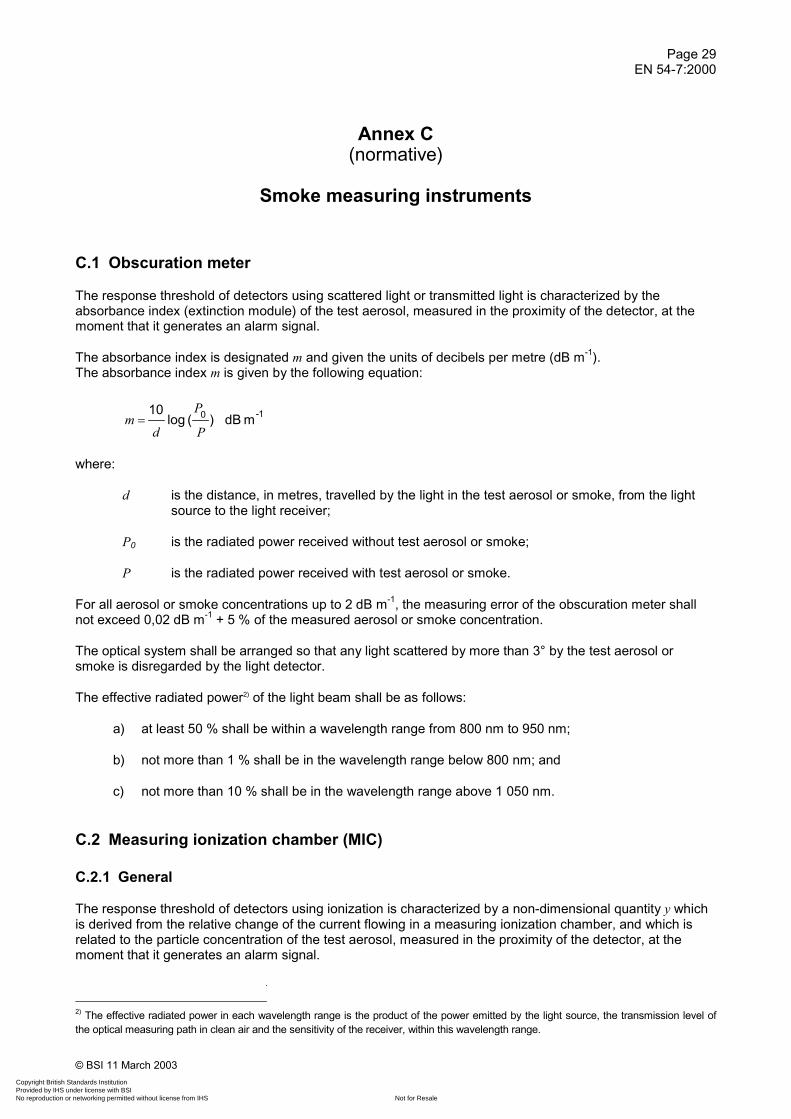
The response threshold of detectors using scattered light or transmitted light is characterized by theabsorbance index (extinction module) of the test aerosol, measured in the proximity of the detector, at themoment that it generates an alarm signal.
The absorbance index is designated m and given the units of decibels per metre (dB m-1).The absorbance index m is given by the following equation:
1-0 mdB)(log10
P
P
dm �
where:
d is the distance, in metres, travelled by the light in the test aerosol or smoke, from the lightsource to the light receiver;
P0 is the radiated power received without test aerosol or smoke;
P is the radiated power received with test aerosol or smoke.
For all aerosol or smoke concentrations up to 2 dB m-1, the measuring error of the obscuration meter shallnot exceed 0,02 dB m-1 + 5 % of the measured aerosol or smoke concentration.
The optical system shall be arranged so that any light scattered by more than 3° by the test aerosol orsmoke is disregarded by the light detector.
The effective radiated power2) of the light beam shall be as follows:
a) at least 50 % shall be within a wavelength range from 800 nm to 950 nm;
b) not more than 1 % shall be in the wavelength range below 800 nm; and
c) not more than 10 % shall be in the wavelength range above 1 050 nm.
C.2 Measuring ionization chamber (MIC)
C.2.1 General
The response threshold of detectors using ionization is characterized by a non-dimensional quantity y whichis derived from the relative change of the current flowing in a measuring ionization chamber, and which isrelated to the particle concentration of the test aerosol, measured in the proximity of the detector, at themoment that it generates an alarm signal.
2) The effective radiated power in each wavelength range is the product of the power emitted by the light source, the transmission level ofthe optical measuring path in clean air and the sensitivity of the receiver, within this wavelength range.
Copyright British Standards Institution Provided by IHS under license with BSI
Not for ResaleNo reproduction or networking permitted without license from IHS
--`,``-`-`,,`,,`,`,,`---

Page 30EN 54-7:2000
© BSI 11 March 2003
C.2.2 Operating method and basic construction
The mechanical construction of the measuring ionization chamber is shown in annex M.
The measuring device consists of a measuring chamber, an electronic amplifier and a method ofcontinuously sucking in a sample of the aerosol or smoke to be measured.
The principle of operation of the measuring ionization chamber is shown in Figure C.1. The measuringchamber contains a measuring volume and a suitable means by which the sampled air is sucked in andpasses the measuring volume in such a way that the aerosol/smoke particles diffuse into this volume. Thisdiffusion is such that the flow of ions within the measuring volume is not disturbed by air movements.
The air within the measuring volume is ionized by alpha radiation from an americium radioactive source,such that there is a bipolar flow of ions when an electrical voltage is applied between the electrodes. Thisflow of ions is affected by the aerosol or smoke particles in a known manner. The relative variation in thecurrent of ions is used as a measurement of the aerosol or smoke concentration.
The measuring chamber is so dimensioned and operated that the following relationships apply:
)()(and0
0
I
I
I
IyydZ η �����
where:
I0 is the chamber current in air without test aerosol or smoke;
I is the chamber current in air with test aerosol or smoke;
� is the chamber constant;
Z is the particle concentration in particles per m3;
d is the average particle diameter.
The non-dimensional quantity y, which is approximately proportional to the particle concentration for aparticular type of aerosol or smoke, is used as a measure of response threshold value for smoke detectorsusing ionization.
Copyright British Standards Institution Provided by IHS under license with BSI
Not for ResaleNo reproduction or networking permitted without license from IHS
--`,``-`-`,,`,,`,`,,`---

Page 31EN 54-7:2000
© BSI 11 March 2003
���������
�������������������������� ��
����
������������������������
��������������
� ����������
1
2
3
44
5
6789101112
13
14
Key1 suction nozzle 6 inner grid 11 guard ring2 assembly plate 7 � rays 12 insulating material3 insulating ring 8 � source 13 windshield4 air/smoke entry 9 measuring volume 14 electronics5 outer grid 10 measuring electrode
Figure C.1 — Measuring ionization chamber — Method of operation
Copyright British Standards Institution Provided by IHS under license with BSI
Not for ResaleNo reproduction or networking permitted without license from IHS
--`,``-`-`,,`,,`,`,,`---

Page 32EN 54-7:2000
© BSI 11 March 2003
C.2.3 Technical data
a) Radiation source:
Isotope: Americium Am241.
Activity: 130 kBq (3,5 �Ci) ± 5 %.
Average α energy: 4,5 MeV ± 5 %.
Mechanical construction: Americium oxide embedded in gold between two layers of gold, coveredwith a hard gold alloy. The source is in the form of a circular disc with adiameter of 27 mm, which is mounted in a holder such that no cut edgesare accessible.
b) Ionization chamber:
The chamber impedance (i.e. the reciprocal of the slope of the current vs voltage characteristic ofthe chamber in its linear region (chamber current � 100 pA)) shall be 1,9 � 1011 ± 5 %, whenmeasured in aerosol- and smoke-free air at:
pressure: (101,3 ± 1) kPa;
temperature: (25 ± 2) °C;
relative humidity: (55 ± 20) %;
with the potential of the guard ring within ± 0,1 V of the voltage of the measuring electrode.
c) Current measuring amplifier:
The chamber is operated in the circuit shown in Figure C.2, with the supply voltage such that thechamber current between the measuring electrodes is 100 pA in aerosol- or smoke-free air. Theinput impedance of the current measuring device shall be < 109 .
d) Suction system:
The suction system shall draw air through the device at a continuous steady flow of 30 l min-1 ± 10 %at atmospheric pressure.
Copyright British Standards Institution Provided by IHS under license with BSI
Not for ResaleNo reproduction or networking permitted without license from IHS
--`,``-`-`,,`,,`,`,,`---

Page 33EN 54-7:2000
© BSI 11 March 2003
1
2
34
5
6
Key1 supply voltage 4 current measuring amplifier2 measuring electrode 5 output voltage proportional to chamber current3 guard ring 6 input impedance, Zin < 109
Figure C.2 — Measuring ionization chamber — Operating circuit
Copyright British Standards Institution Provided by IHS under license with BSI
Not for ResaleNo reproduction or networking permitted without license from IHS
--`,``-`-`,,`,,`,`,,`---

Page 34EN 54-7:2000
© BSI 11 March 2003
Annex D(normative)
Apparatus for dazzling test
The apparatus (see Figure D.1) shall be constructed so that it can be inserted in the working section of thesmoke tunnel. Four of the cube faces shall be closed and lined on the inside with high gloss aluminium foil;two opposing cube faces shall be open so that the test aerosol can flow through the device.Circular fluorescent lamps (32 W) with a diameter of approximately 30 cm shall be fitted to the closedsurfaces of the cube.
The detector to be tested shall be installed within the cube (see Figure D.1) so that light can play on it fromabove, below and from two sides.
NOTE: Care should be taken with the electrical connections to the fluorescent lamps to avoid electricalinterference with the detection system.
Dimensions in millimetres
380
AB
CD
E F
GH
1
380
380
Sides ABCD and EFGH shall be open to allow for the flow of aerosol.
Sides ABFE, AEHD, BFGC and DCGH shall have lamps mounted as shown below:
2
Key1 stream of aerosol2 fluorescent lamp
Figure D.1 — Dazzling apparatus
Copyright British Standards Institution Provided by IHS under license with BSI
Not for ResaleNo reproduction or networking permitted without license from IHS
--`,``-`-`,,`,,`,`,,`---

Page 35EN 54-7:2000
© BSI 11 March 2003
Annex E(informative)
Apparatus for impact test
The apparatus (see Figure E.1) consists essentially of a swinging hammer comprising a rectangular sectionhead (striker), with a chamfered impact face, mounted on a tubular steel shaft. The hammer is fixed into asteel boss, which runs on ball bearings on a fixed steel shaft mounted in a rigid steel frame, so that thehammer can rotate freely about the axis of the fixed shaft. The design of the rigid frame is such as to allowcomplete rotation of the hammer assembly when the specimen is not present.
The striker is of dimensions 76 mm wide, 50 mm high and 94 mm long (overall dimensions) and ismanufactured from aluminium alloy (Al Cu4 Si Mg to ISO 209-1:1989), solution treated andprecipitation treated condition. It has a plane impact face chamfered at (60 ± 1)° to the long axis of the head.The tubular steel shaft has an outside diameter of (25 ± 0,1) mm with walls (1,6 ± 0,1) mm thick.
The striker is mounted on the shaft so that its long axis is at a radial distance of 305 mm from the axis ofrotation of the assembly, the two axes being mutually perpendicular. The central boss is 102 mm inoutside diameter and 200 mm long and is mounted coaxially on the fixed steel pivot shaft, which isapproximately 25 mm in diameter, however the precise diameter of the shaft will depend on the bearingsused.
Diametrically opposite the hammer shaft are two steel counter balance arms, each 20 mm inoutside diameter and 185 mm long. These arms are screwed into the boss so that a length of 150 mmprotrudes. A steel counter balance weight is mounted on the arms so that its position can be adjusted tobalance the weight of the striker and arms, as in Figure E.1. On the end of the central boss is mounted a12 mm wide � 150 mm diameter aluminium alloy pulley and round this an inextensible cable is wound,one end being fixed to the pulley. The other end of the cable supports the operating weight.
The rigid frame also supports the mounting board on which the specimen is mounted by its normal fixings.The mounting board is adjustable vertically so that the upper half of the impact face of the hammer will strikethe specimen when the hammer is moving horizontally, as shown in Figure E.1.
To operate the apparatus, the position of the specimen and the mounting board is first adjusted as shown inFigure E.1 and the mounting board is then secured rigidly to the frame. The hammer assembly is thenbalanced carefully by adjustment of the counter balance weight with the operating weight removed. Thehammer arm is then drawn back to the horizontal position ready for release and the operating weight isreinstated. On release of the assembly the operating weight will spin the hammer and arm through an angleof 3/2 radians to strike the specimen. The mass of the operating weight to produce the required impactenergy of 1,9 J equals:
kg3
0,388r�
where r is the effective radius of the pulley in metres. This equals approximately 0,55 kg for a pulley radius of75 mm.
As the standard calls for a hammer velocity at impact of (1,5 ± 0,13) m s-1, the mass of the hammer head willneed to be reduced by drilling the back face sufficiently to obtain this velocity. It is estimated that a head ofmass of about 0,79 kg will be required to obtain the specified velocity, but this will have to be determined bytrial and error.
Copyright British Standards Institution Provided by IHS under license with BSI
Not for ResaleNo reproduction or networking permitted without license from IHS
--`,``-`-`,,`,,`,`,,`---

Page 36EN 54-7:2000
© BSI 11 March 2003
Dimensions in millimetres
2
5
11
6
10
1
3
4
98
7
50
76
200 12
102
150
305
150
50
25
55 55
150
270º
80
25
60
20
38
Key1 mounting board 7 270° angle of movement2 detector 8 ball bearings3 striker 9 counter balance arms4 striker shaft 10 operating weight5 boss 11 counterbalance weight6 pulley
NOTE: The dimensions shown are for guidance, apart from those relating to the hammer head.
Figure E.1 — Impact apparatus
Copyright British Standards Institution Provided by IHS under license with BSI
Not for ResaleNo reproduction or networking permitted without license from IHS
--`,``-`-`,,`,,`,`,,`---

Page 37EN 54-7:2000
© BSI 11 March 2003
Annex F(normative)
Fire test roomThe specimens to be tested, the MIC, the temperature probe and the measuring part of theobscuration meter shall all be located within the volume shown in Figures F.1 & F.2.
The specimens, the MIC and the mechanical parts of the obscuration meter shall be at least 100 mm apart,measured to the nearest edges. The centre line of the beam of the obscuration meter shall be at least35 mm below the ceiling.
1
2
3 m
60°
9 - 11 m
6 -
8 m
==
= =
Key1 specimens and measuring instruments (see Figure F.2)2 position of test fire
Figure F.1 — Plan view of the fire test room
Copyright British Standards Institution Provided by IHS under license with BSI
Not for ResaleNo reproduction or networking permitted without license from IHS
--`,``-`-`,,`,,`,`,,`---

Page 38EN 54-7:2000
© BSI 11 March 2003
15 c
m
3 m
60°
1
30 cm
Key1 ceiling
Figure F.2 — Mounting position for specimens and measuring instruments
Copyright British Standards Institution Provided by IHS under license with BSI
Not for ResaleNo reproduction or networking permitted without license from IHS
--`,``-`-`,,`,,`,`,,`---

Page 39EN 54-7:2000
© BSI 11 March 2003
Annex G(normative)
Smouldering (pyrolysis) wood fire (TF2)
G.1 Fuel
Approximately 10 dried beechwood sticks (moisture content � 5 %), each stick having dimensions of75 mm � 25 mm � 20 mm.
G.2 Hotplate
The hotplate shall have a 220 mm diameter grooved surface with eight concentric grooves, each 2 mm deepand 5 mm wide, with the outer groove 4 mm from the edge and a distance of 3 mm between grooves. Thehotplate shall have a rating of approximately 2 kW.
The temperature of the hotplate shall be measured by a sensor attached to the fifth groove, counted from theedge of the hotplate, and secured to provide a good thermal contact.
G.3 Arrangement
The sticks shall be arranged on the grooved hotplate surface, with the 20 mm side in contact with the surfacesuch that the temperature probe lies between the sticks and is not covered, as shown in Figure G.1.
12
3
Key1 grooved hotplate2 temperature sensor3 wooden sticks
Figure G.1 — Arrangement of the sticks on the hotplate
Copyright British Standards Institution Provided by IHS under license with BSI
Not for ResaleNo reproduction or networking permitted without license from IHS
--`,``-`-`,,`,,`,`,,`---

Page 40EN 54-7:2000
© BSI 11 March 2003
G.4 Heating rate
The hotplate shall be powered such that its temperature rises from ambient to 600 °C in approximately11 min.
G.5 End of test condition
mE = 2 dB m-1
G.6 Test validity criteria
The development of the fire shall be such that the curves of m against y, and m against time, fall within thelimits shown in Figures G.2 and G.3 respectively and no flaming occurs, up to the time when all of thespecimens have generated an alarm signal, or m = 2 dB m-1, whichever is the earlier.
If the end of test condition, mE = 2 dB m-1, is reached before all the specimens of detectors using ionizationhave responded, then the test is only considered valid if a y-value of 1,6 has been reached.
2,0
0,6
0,1 2,051,23
(dB m )-1
1
2
0,05
150 400 570 840
2,0
(dB m )-1
(s)
1
2
Key Key1 m-value 1 m-value2 y-value 2 time
Figure G.2 — Limits for m against y,Fire TF2
Figure G.3 — Limits for m against time,Fire TF2
Copyright British Standards Institution Provided by IHS under license with BSI
Not for ResaleNo reproduction or networking permitted without license from IHS
--`,``-`-`,,`,,`,`,,`---

Page 41EN 54-7:2000
© BSI 11 March 2003
Annex H(normative)
Glowing smouldering cotton fire (TF3)
H.1 Fuel
Approximately 90 pieces of braided cotton wick, each approximately 80 cm long and weighing approximately3 g. The wicks shall be free from any protective coating and shall be washed and dried if necessary.
H.2 Arrangement
The wicks shall be fastened to a ring approximately 10 cm in diameter and suspended approximately 1 mabove a non combustible plate as shown in Figure H.1.
1 m
≈
Figure H.1 — Arrangement of the cotton wicks
Copyright British Standards Institution Provided by IHS under license with BSI
Not for ResaleNo reproduction or networking permitted without license from IHS
--`,``-`-`,,`,,`,`,,`---
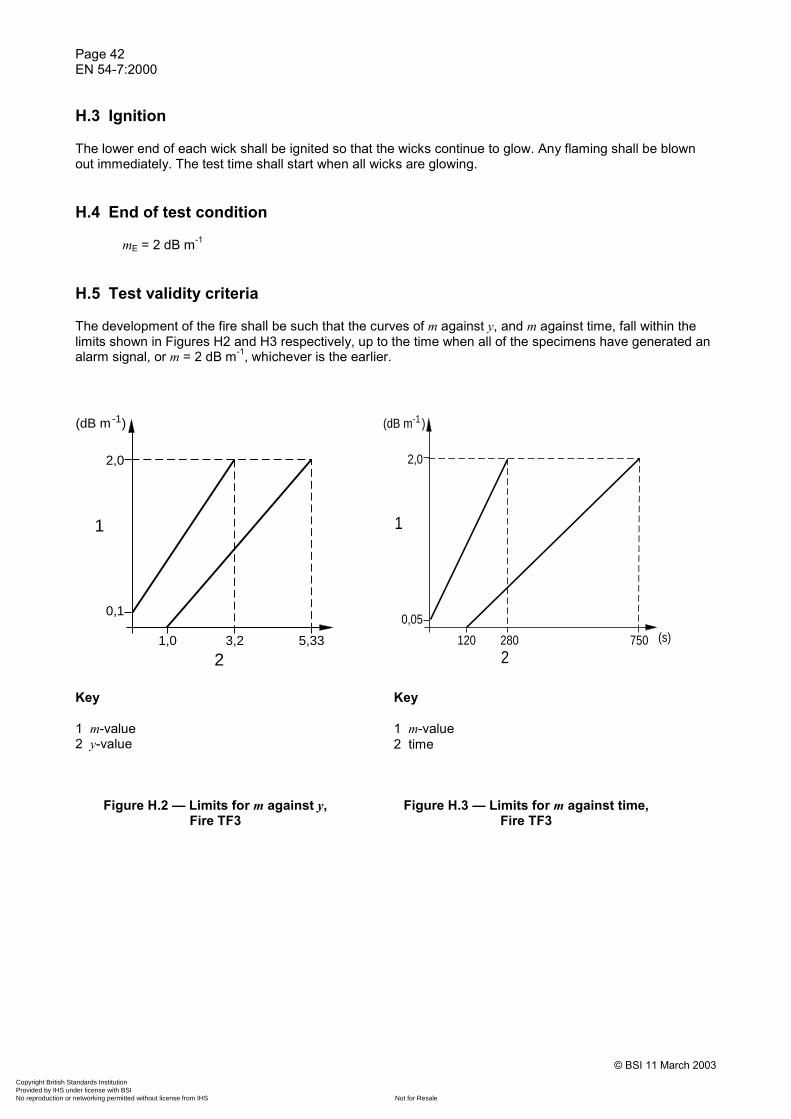
Page 42EN 54-7:2000
© BSI 11 March 2003
H.3 Ignition
The lower end of each wick shall be ignited so that the wicks continue to glow. Any flaming shall be blownout immediately. The test time shall start when all wicks are glowing.
H.4 End of test condition
mE = 2 dB m-1
H.5 Test validity criteria
The development of the fire shall be such that the curves of m against y, and m against time, fall within thelimits shown in Figures H2 and H3 respectively, up to the time when all of the specimens have generated analarm signal, or m = 2 dB m-1, whichever is the earlier.
0,1
2,0
1,0 3,2 5,33
(dB m )-1
1
2
0,05
2,0
120 280 750 (s)
(dB m )-1
1
2
Key Key
1 m-value 1 m-value2 y-value 2 time
Figure H.2 — Limits for m against y,Fire TF3
Figure H.3 — Limits for m against time,Fire TF3
Copyright British Standards Institution Provided by IHS under license with BSI
Not for ResaleNo reproduction or networking permitted without license from IHS
--`,``-`-`,,`,,`,`,,`---

Page 43EN 54-7:2000
© BSI 11 March 2003
Annex I(normative)
Flaming plastics (polyurethane) fire (TF4)
I.1 Fuel
Soft polyurethane foam, without flame retardant additives and having a density of approximately 20 kg m-3.3 mats, approximately 50 cm � 50 cm � 2 cm, are usually found sufficient, however the exact fuel quantitymay be adjusted to obtain valid tests.
I.2 Arrangement
The mats shall be placed one on top of another on a base formed from aluminium foil with the edges foldedup to provide a tray.
I.3 Ignition
The mats shall normally be ignited at a corner of the lower mat, however the exact position of ignition may beadjusted to obtain valid tests. A small quantity of a clean burning material (e.g. 5 cm3 of methylated spirit)may be used to assist the ignition.
I.4 End of test condition
yE = 6
I.5 Test validity criteria
The development of the fire shall be such that the curves of m against y, and m against time, fall within thelimits shown in Figures I.1 and I.2 respectively, up to the time when all of the specimens have generated analarm signal, or y = 6, whichever is the earlier.
Copyright British Standards Institution Provided by IHS under license with BSI
Not for ResaleNo reproduction or networking permitted without license from IHS
--`,``-`-`,,`,,`,`,,`---
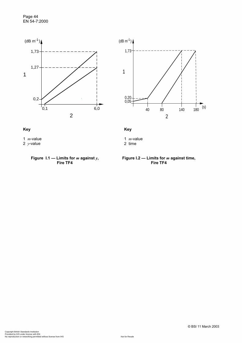
Page 44EN 54-7:2000
© BSI 11 March 2003
1,73
1,27
0,2
0,1 6,0
(dB m )-1
1
2
(s)40 80 140 180
0,050,20
1,73
(dB m )-1
1
2
Key Key
1 m-value 1 m-value2 y-value 2 time
Figure I.1 — Limits for m against y,Fire TF4
Figure I.2 — Limits for m against time,Fire TF4
Copyright British Standards Institution Provided by IHS under license with BSI
Not for ResaleNo reproduction or networking permitted without license from IHS
--`,``-`-`,,`,,`,`,,`---

Page 45EN 54-7:2000
© BSI 11 March 2003
Annex J(normative)
Flaming liquid (n-heptane) fire (TF5)
J.1 Fuel
Approximately 650 g of a mixture of n-heptane (purity � 99 %) with approximately 3 % of toluene(purity � 99 %), by volume. The precise quantities may be varied to obtain valid tests.
J.2 Arrangement
The heptane/toluene mixture shall be burnt in a square steel tray with dimensions approximately33 cm � 33 cm � 5 cm.
J.3 Ignition
Ignition shall be by flame or spark etc.
J.4 End of test condition
yE = 6
J.5 Test validity criteria
The development of the fire shall be such that the curves of m against y, and m against time, fall within thelimits shown in Figures J.1 and J.2 respectively, up to the time when all of the specimens have generated analarm signal, or y = 6, whichever is the earlier.
If the end of test condition, yE = 6, is reached before all the specimens of detectors using scattered ortransmitted light have responded, then the test is only considered valid if an m-value of 1,1 dB m-1 has beenreached.
Copyright British Standards Institution Provided by IHS under license with BSI
Not for ResaleNo reproduction or networking permitted without license from IHS
--`,``-`-`,,`,,`,`,,`---

Page 46EN 54-7:2000
© BSI 11 March 2003
0,92
1,24
0,10
0,1 6,0
(dBm )-1
1
2
1,24
0,20
10 120 240
(dBm )-1
(s)
1
2
Key Key
1 m-value 1 m-value2 y-value 2 time
Figure J.1 — Limits for m against y,Fire TF5
Figure J.2 — Limits for m against time,Fire TF5
Copyright British Standards Institution Provided by IHS under license with BSI
Not for ResaleNo reproduction or networking permitted without license from IHS
--`,``-`-`,,`,,`,`,,`---
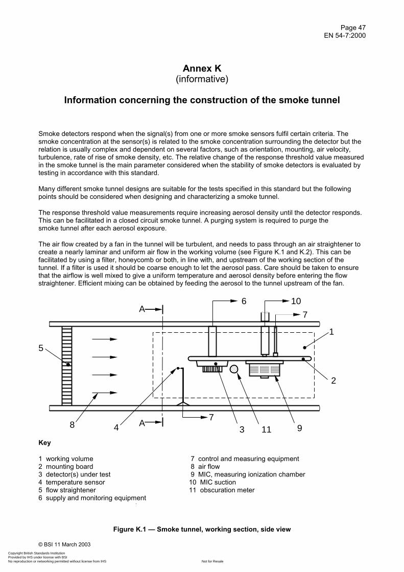
Page 47EN 54-7:2000
© BSI 11 March 2003
Annex K(informative)
Information concerning the construction of the smoke tunnel
Smoke detectors respond when the signal(s) from one or more smoke sensors fulfil certain criteria. Thesmoke concentration at the sensor(s) is related to the smoke concentration surrounding the detector but therelation is usually complex and dependent on several factors, such as orientation, mounting, air velocity,turbulence, rate of rise of smoke density, etc. The relative change of the response threshold value measuredin the smoke tunnel is the main parameter considered when the stability of smoke detectors is evaluated bytesting in accordance with this standard.
Many different smoke tunnel designs are suitable for the tests specified in this standard but the followingpoints should be considered when designing and characterizing a smoke tunnel.
The response threshold value measurements require increasing aerosol density until the detector responds.This can be facilitated in a closed circuit smoke tunnel. A purging system is required to purge thesmoke tunnel after each aerosol exposure.
The air flow created by a fan in the tunnel will be turbulent, and needs to pass through an air straightener tocreate a nearly laminar and uniform air flow in the working volume (see Figure K.1 and K.2). This can befacilitated by using a filter, honeycomb or both, in line with, and upstream of the working section of thetunnel. If a filter is used it should be coarse enough to let the aerosol pass. Care should be taken to ensurethat the airflow is well mixed to give a uniform temperature and aerosol density before entering the flowstraightener. Efficient mixing can be obtained by feeding the aerosol to the tunnel upstream of the fan.
����
1
2
3 114
5
6
7
7
10
8 9A
A
Key
1 working volume 7 control and measuring equipment2 mounting board 8 air flow3 detector(s) under test 9 MIC, measuring ionization chamber4 temperature sensor 10 MIC suction5 flow straightener 11 obscuration meter6 supply and monitoring equipment
Figure K.1 — Smoke tunnel, working section, side view
Copyright British Standards Institution Provided by IHS under license with BSI
Not for ResaleNo reproduction or networking permitted without license from IHS
--`,``-`-`,,`,,`,`,,`---

Page 48EN 54-7:2000
© BSI 11 March 2003
A - A
1
2
3
4
5
6
7
Key
1 working volume2 mounting board3 detector(s) under test4 temperature sensor5 obscuration meter6 MIC, measuring ionization chamber7 reflector for obscuration meter
Figure K.2 — Smoke tunnel, working section, cross section A-A
Means for heating the air before it enters the working section are required. The tunnel should have a systemcapable of controlling the heating as to achieve the specified temperatures and temperature profiles in theworking volume. The heating should be achieved by means of low temperature heaters to avoid theproduction of extraneous aerosols or alteration of the test aerosol.
Special attention should be given to the arrangement of the elements in the working volume in order to avoiddisturbance of the test conditions e.g. due to turbulence. The suction through the MIC creates a mean airvelocity of approximately 0,04 m s-1 in the plane of the entrance openings in the chamber housing. However,the effect of the suction will be negligible if the MIC is placed 10 cm to 15 cm downstream of the detectorposition.
The smoke tunnel may be designed for aerosol-free wind exposures with 5 m s-1 and 10 m s-1, provided thisdoes not interfere with the operation when the tunnel is used for response threshold value measurements.
Copyright British Standards Institution Provided by IHS under license with BSI
Not for ResaleNo reproduction or networking permitted without license from IHS
--`,``-`-`,,`,,`,`,,`---

Page 49EN 54-7:2000
© BSI 11 March 2003
Annex L(informative)
Information concerning the requirements for the responseto slowly developing fires
A simple detector operates by comparing the signal from the sensor with a certain fixed threshold(alarm threshold). When the sensor signal reaches the threshold, the detector generates an alarm signal.The smoke density at which this occurs is the response threshold value for the detector. In this simpledetector the alarm threshold is fixed and does not depend on the rate of change of sensor signal with time.
It is known that the sensor signal in clean air can change over the life of the detector. Such changes can becaused, for example, by contamination of the sensing chamber with dust or by other long-term effects suchas component ageing. This drift can, in time, lead to increased sensitivity and eventually to false alarms.
It may be considered beneficial therefore to provide compensation for such drift in order to maintain a moreconstant level of response threshold value with time. For the purposes of this discussion it is assumed thatthe compensation is achieved by increasing the alarm threshold to offset some or all of the upward drift in thesensor output.
Any compensation for drift will reduce the sensitivity of the detector to slow changes in the sensor outputeven if these changes are caused by a real, but gradual, increase in smoke level. The object ofrequirement 4.8 a) is to ensure that the compensation does not reduce the sensitivity to a slowly developingfire to an unacceptable degree.
For the purposes of this standard it is assumed that the development of any fire which presents a seriousdanger to life or property will be such that the sensor output will change at a rate of at least A/4 per hourwhere A is the nominal response threshold value of the detector. The response to rates of change less thanA/4 per hour is not specified in this standard, and there is therefore no requirement for the detector torespond to these lower rates of change.
In order not to restrict the way in which compensation is achieved, 4.8 requires only that the time to alarm,for all rates of change greater than A/4 per hour, does not exceed 1,6 � the time to alarm, if thecompensation were not present.
If the threshold increases in a linear fashion with time in response to a rise in the sensor signal, and if theextent of the compensation is not limited, then the maximum rate of compensation allowed can be seen fromFigure L.1 to be 0,6A/6,4 = 0,094A per hour, since at this compensation rate the sensor output will reach thecompensated threshold in exactly 6,4 h.
Although it has been assumed above that the threshold is compensated linearly and continuously, theprocess need not be linear or continuous. For example, the stepwise adjustment shown in Figure L.2 alsomeets the requirement since, in this case, an alarm is reached in 6 h, which is less than the limiting value of6,4 h.
Copyright British Standards Institution Provided by IHS under license with BSI
Not for ResaleNo reproduction or networking permitted without license from IHS
--`,``-`-`,,`,,`,`,,`---

Page 50EN 54-7:2000
© BSI 11 March 2003
0
0,5
1,0
1,5
2
0 1 2 3 4 5 6 7 8
1
3
4
2
0,25 Ah
0,094 Ah-1
-1
(h)
Key
1 Relative alarm threshold (relative to A) 3 Compensated alarm threshold2 Time 4 Sensor output
Figure L.1 — Linear compensation — limiting case
0
0,5
1,0
1,5
2
0 1 2 3 4 5 6 7 8
1
2
0,25 Ah-1
3
4
(h)
Key
1 Relative alarm threshold (relative to A) 3 Compensated alarm threshold2 Time 4 Sensor output
Figure L.2 — Stepwise compensation — limiting case
Copyright British Standards Institution Provided by IHS under license with BSI
Not for ResaleNo reproduction or networking permitted without license from IHS
--`,``-`-`,,`,,`,`,,`---

Page 51EN 54-7:2000
© BSI 11 March 2003
Furthermore, the rate of compensation need not be limited to 0,094A per hour if the extent of thecompensation is restricted to 0,6A. The relatively rapid rate of compensation shown in Figure L.3 also meetsthe requirement in reaching an alarm condition in 6,4 hours. In this case the maximum rate of compensationwill be limited only by the requirements of the test fires.
0
0,5
1,0
1,5
2
0 1 2 3 4 5 6 7 8
1
2
1,6
0,25 Ah
0,25 Ah
-1
-1
3
4
(h)
Key
1 Relative alarm threshold (relative to A) 3 Compensated alarm threshold2 Time 4 Sensor output
Figure L.3 — High-rate, limited-extent compensation
The requirements of 4.8 a) allow considerable freedom in the way in which compensation for slow changes isachieved. However, it is recognized that in any practical detector the range over which the output of thesensor is linearly related to smoke (or other stimulus which is equivalent to smoke) is finite. If the range ofcompensation takes the sensor output into this non-linear region then the sensitivity of the detector couldbecome degraded to an unacceptable degree.
As an example, consider a detector having the transfer characteristic shown in Figure L.4, in which both axesare expressed in terms of response threshold value A. The non-linearity of the characteristic causes theeffective sensitivity to reduce at higher values of stimulus. In this instance, it is necessary to limit thecompensation to less than 1,1 � A, since in order to produce a change in output of A, the stimulus has toincrease from 1,1 � A to 2,7 � A. This reduction in sensitivity by a factor of 1,6 represents the maximumallowed by 4.8 b).
Copyright British Standards Institution Provided by IHS under license with BSI
Not for ResaleNo reproduction or networking permitted without license from IHS
--`,``-`-`,,`,,`,`,,`---

Page 52EN 54-7:2000
© BSI 11 March 2003
0,0
0,5
1,0
1,5
2,0
2,5
0,0 0,5 1,0 1,5 2,0 2,5 3,0
1
2
1,6
1,0
Key
1 Output2 Stimulus
Figure L.4 — Example of non-linear transfer characteristic
Copyright British Standards Institution Provided by IHS under license with BSI
Not for ResaleNo reproduction or networking permitted without license from IHS
--`,``-`-`,,`,,`,`,,`---

Page 53EN 54-7:2000
© BSI 11 March 2003
Annex M(informative)
Information concerning the construction of the measuring ionizationchamber
The mechanical construction of the measuring ionization chamber3) is shown in Figure M.1. The functionallyimportant dimensions are marked with their tolerances. Further details of the various parts of the device aregiven in Table M.1.
Table M.1 — List of parts of the measuring ionization chamber
ReferenceNo.
Item Numberprovided
Dimensions,Special features
Material
1 Insulating ring 1 Polyamide2 Multipole socket 1 10-pole3 Measuring electrode terminal 1 To chamber supply4 Measuring electrode terminal 1 To amplifier or current
measuring device5 Suction nozzle 16 Guide socket 4 Polyamide7 Housing 1 Aluminium8 Insulating plate 1 Polycarbonate9 Guard ring 1 Stainless steel10 Measuring electrode 1 Stainless steel11 Assembly plate 1 Aluminium12 Fixing screw with milled nut 3 M3 Nickel plated brass13 Cover 1 Six openings Stainless steel14 Outer grid 1 Wire 0,2 mm diameter
0,8 mm internal mesh widthStainless steel
15 Inner grid 1 Wire 0,4 mm diameter1,6 mm internal mesh width
Stainless steel
16 Windshield 1 Stainless steel17 Intermediate ring 1 With 72 equispaced holes
each 2 mm diameter18 Threaded ring 1 Nickel plated brass19 Source holder 1 Nickel plated brass20 Source 1 27 mm diameter See C.2.321 Openings on the periphery 6
3) The measuring ionization chamber is fully described in “Investigation of ionization chamber for reference measurements of smoke density”by M. Avlund, published by DELTA Electronics, Venlighedsvej 4 DK-2970 Hørsholm, Denmark.
Copyright British Standards Institution Provided by IHS under license with BSI
Not for ResaleNo reproduction or networking permitted without license from IHS
--`,``-`-`,,`,,`,`,,`---

Page 54EN 54-7:2000
© BSI 11 March 2003
Dimensions in millimetres
Ø 7,5
Ø 27
55
Ø 80 ± 0,5
Ø 100 ± 2
Ø 124 ± 5
Ø 30 ± 0,1
75 ±
5
30 ±
14
5
15 ± 1
Ø 2 5 ±
1
20 ±
2
10 ±
1
40
5
3 2
4
6 7
11
1
12
1489151610
17
13
18
19
20
21
NOTE 1: See Table M.1 for the list of parts.
NOTE 2: Dimensions without a tolerance marked are recommended dimensions.
Figure M.1 — Mechanical construction of the measuring ionization chamber
Copyright British Standards Institution Provided by IHS under license with BSI
Not for ResaleNo reproduction or networking permitted without license from IHS
--`,``-`-`,,`,,`,`,,`---

Page 55EN 54-7:2000
© BSI 11 March 2003
�Annex ZA(informative)
Clauses of this European Standard addressing essential requirementsor other provisions of EU Directives
ZA.1 Scope and relevant clauses
This European Standard has been prepared under the mandate M/109 given to CEN by the EuropeanCommission and the European Free Trade Association.
The clauses of this European Standard, shown in this annex, meet the requirements of the Mandate givenunder the EU Construction Products Directive (89/106/EEC).
Compliance with these clauses confers a presumption of fitness of the construction product covered by thisEuropean Standard for its intended use according to clause 1 (Scope) of this standard.
WARNING: Other requirements and other EU Directives may be applicable to the product(s) falling within thescope of this standard.
NOTE 1 In addition to any specific clauses relating to dangerous substances contained in this standard, there may beother requirements applicable to the products falling within its scope (e.g. transposed European legislation and nationallaws, regulations and administrative provisions). These requirements need also to be complied with, when and wherethey apply.
NOTE 2 An informative database of European and national provisions on dangerous substances is available at theConstruction web site on EUROPA (CREATE, accessed throughhttp://europa.eu.int/comm/enterprise/construction/internal/hygiene.thm)
This annex ZA has the same scope, in relation to the products covered, as clause 1 of this standard. Thisannex establishes the conditions for the CE marking of point smoke detectors intended for the use shownbelow and identifies the relevant clauses applicable.�
Copyright British Standards Institution Provided by IHS under license with BSI
Not for ResaleNo reproduction or networking permitted without license from IHS
--`,``-`-`,,`,,`,`,,`---

Page 56EN 54-7:2000
© BSI 11 March 2003
�Construction Product: Smoke detectors — Point detectors using scattered light, transmitted
light or ionization for fire detection and fire alarm systems forbuildings.
Intended use: Fire Safety.
Table ZA.1 — Relevant clauses
Essential characteristics Clauses in thisEuropean Standard
Mandatedlevel(s)
Notes
Nominal activation conditions/Sensitivity,Response delay (response time) andPerformance under fire conditions
4.8, 5.2, 5.3, 5.4, 5.6,5.7, 5.18
Operational reliability 4.2 to 4.7, 4.9 to 4.11Tolerance to supply voltage 5.5Durability of operational reliability and responsedelay; temperature resistance
5.8, 5.9 None
Durability of operational reliability; vibrationresistance
5.13 to 5.16
Durability of operational reliability; humidityresistance
5.10, 5.11
Durability of operational reliability; corrosionresistance
5.12
Durability of operational reliability; electricalstability
5.17
ZA.2 Procedures for the attestation of conformity of point smoke detectors covered by this standard
ZA.2.1 System of attestation of conformity
The mandate requires that the attestation of conformity system to be applied shall be that shown inTable ZA.2.
Table ZA.2 — Attestation of conformity system
Product Intended use Levels orclasses
Attestation ofconformity system
Fire detection/Fire alarm:Smoke detectors — Point detectorsusing scattered light, transmitted lightor ionization
Fire safety None 1
System 1: See CPD Annex III.2.(i), without audit-testing of samples�
Copyright British Standards Institution Provided by IHS under license with BSI
Not for ResaleNo reproduction or networking permitted without license from IHS
--`,``-`-`,,`,,`,`,,`---

Page 57EN 54-7:2000
© BSI 11 March 2003
�This requires:
a) Tasks to be provided by the manufacturer:
1) factory production control (see ZA.2.2b);2) testing of samples taken at the factory by the manufacturer in accordance with a prescribed test
plan;
b) Tasks to be undertaken under the authority of a Notified Product Certification Body4:
1) type testing of the product;2) inspection of the factory and factory production control;3) continuous/periodic surveillance, assessment and approval of the factory production control.
ZA.2.2 Evaluation of conformity
The evaluation of conformity of point smoke detectors covered by this European Standard shall be by thefollowing:
a) Type testing
Type testing of the product shall be carried out in accordance with the clauses shown in Table ZA.1.The products tested shall be representative of the manufacturer’s normal production with regard totheir construction, operation and calibration. Tests previously performed in accordance with theprovisions of this standard may be taken into account providing that they were made to the samesystem of attestation of conformity on the same product or products of similar design, construction andfunctionality, such that the results may be considered applicable to the product in question. Wherevera change, for example in the product design, materials or supplier of the components or of theproduction process occurs, which could change significantly one or more of the characteristics, thetype testing shall be repeated for the relevant product performance.
b) Factory production control
The manufacturer shall establish, document and maintain a permanent factory production controlsystem to ensure that the products placed on the market conform with the stated performancecharacteristics. The factory production control system shall consist of procedures, regular inspectionsand tests and/or assessments and the use of the results to control incoming materials or components,equipment, the production process and the product.
The production control procedure shall be adequately extensive and detailed so that the conformity ofthe products is made apparent to the manufacturer and so that irregularities can be detected at theearliest possible stage.
A factory production control system conforming with the requirements of EN ISO 9001, and madespecific to the requirements of this standard, should be considered to satisfy the above requirements.
The production control procedure shall be recorded in a manual, which shall be made available forinspection.
4 A Notified Product Certification Body is an approved product certification body notified to the Commission by a member state, for thispurpose, in accordance with article 18 of the Construction Products Directive (89/106/EEC).�
Copyright British Standards Institution Provided by IHS under license with BSI
Not for ResaleNo reproduction or networking permitted without license from IHS
--`,``-`-`,,`,,`,`,,`---

Page 58EN 54-7:2000
© BSI 11 March 2003
�
The factory production control shall be recorded. These records shall be available for inspection and shallinclude at least the following:
1) identification of the product tested;2) the dates of sampling;3) the test methods applied;4) the test and inspection results;5) the date of tests;6) the identification of the responsible authority within the factory;7) calibration records;8) actions taken.
ZA.3 CE Marking and labelling and accompanying documentation
The CE marking symbol (in accordance with Directive 93/68/EEC) shall be placed on the product and beaccompanied by:
i) the identification number of the Notified Product Certification Body;
ii) the number of the EC certificate of conformity.
The CE marking symbol shall in addition be shown on the accompanying commercial documentationsupplemented by:
a) the identification number of the Notified Product Certification Body;
b) the name or identifying mark and registered address of the manufacturer;
c) the last two digits of the year in which the marking was affixed;
d) the number of the EC certificate of conformity;
e) the reference to this European Standard (EN 54-7);
f) the description of the construction product (Point type smoke detector for fire detection and fire alarmsystems for buildings);
g) the type/model designation of the product;
h) the data required by 4.10 or a reference to a document, which shall be uniquely identifiable andavailable from the manufacturer, containing these data.
Where the product exceeds the minimum performance levels stated in this standard, and where themanufacturer so desires, the CE marking may be accompanied by an indication of the parameter(s)concerned and the actual test result(s). �
Copyright British Standards Institution Provided by IHS under license with BSI
Not for ResaleNo reproduction or networking permitted without license from IHS
--`,``-`-`,,`,,`,`,,`---
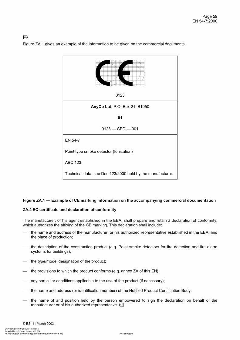
Page 59EN 54-7:2000
© BSI 11 March 2003
�
Figure ZA.1 gives an example of the information to be given on the commercial documents.
0123
AnyCo Ltd, P.O. Box 21, B1050
01
0123 — CPD — 001
EN 54-7
Point type smoke detector (Ionization)
ABC 123
Technical data: see Doc.123/2000 held by the manufacturer.
Figure ZA.1 — Example of CE marking information on the accompanying commercial documentation
ZA.4 EC certificate and declaration of conformity
The manufacturer, or his agent established in the EEA, shall prepare and retain a declaration of conformity,which authorizes the affixing of the CE marking. This declaration shall include:
� the name and address of the manufacturer, or his authorized representative established in the EEA, andthe place of production;
� the description of the construction product (e.g. Point smoke detectors for fire detection and fire alarmsystems for buildings);
� the type/model designation of the product;
� the provisions to which the product conforms (e.g. annex ZA of this EN);
� any particular conditions applicable to the use of the product (if necessary);
� the name and address (or identification number) of the Notified Product Certification Body;
� the name of and position held by the person empowered to sign the declaration on behalf of themanufacturer or of his authorized representative.�
Copyright British Standards Institution Provided by IHS under license with BSI
Not for ResaleNo reproduction or networking permitted without license from IHS
--`,``-`-`,,`,,`,`,,`---

Page 60EN 54-7:2000
© BSI 11 March 2003
�
The declaration shall contain a certificate of conformity with the following information:
� the name and address of the Notified Product Certification Body;
� the certificate number;
� the name and address of the manufacturer, or his authorized representative established in the EEA;
� the description of the construction product (e.g. Point smoke detectors for fire detection and fire alarmsystems for buildings);
� the type/model designation of the product;
� the provisions to which the product conforms (e.g. annex ZA of this EN);
� any particular conditions applicable to the use of the product (if necessary);
� any conditions and period of validity of the certificate, where applicable;
� the name of and position held by the person empowered to sign the certificate.
The above mentioned declaration and certificate shall be presented (if requested) in the official language orlanguages of the Member State in which the product is to be used.�
Copyright British Standards Institution Provided by IHS under license with BSI
Not for ResaleNo reproduction or networking permitted without license from IHS
--`,``-`-`,,`,,`,`,,`---

Page 61EN 54-7:2000
© BSI 11 March 2003
�Bibliography
EN ISO 9001, Quality management systems — Requirements (ISO 9001:2000).�
Copyright British Standards Institution Provided by IHS under license with BSI
Not for ResaleNo reproduction or networking permitted without license from IHS
--`,``-`-`,,`,,`,`,,`---

BS EN 54-7:2001
BSI
389 Chiswick High Road
London
W4 4AL
BSI — British Standards InstitutionBSI is the independent national body responsible for preparing British Standards. It presents the UK view on standards in Europe and at the international level. It is incorporated by Royal Charter.
Revisions
British Standards are updated by amendment or revision. Users of British Standards should make sure that they possess the latest amendments or editions.
It is the constant aim of BSI to improve the quality of our products and services. We would be grateful if anyone finding an inaccuracy or ambiguity while using this British Standard would inform the Secretary of the technical committee responsible, the identity of which can be found on the inside front cover. Tel: +44 (0)20 8996 9000. Fax: +44 (0)20 8996 7400.
BSI offers members an individual updating service called PLUS which ensures that subscribers automatically receive the latest editions of standards.
Buying standards
Orders for all BSI, international and foreign standards publications should be addressed to Customer Services. Tel: +44 (0)20 8996 9001. Fax: +44 (0)20 8996 7001. Email: [email protected]. Standards are also available from the BSI website at http://www.bsi-global.com.
In response to orders for international standards, it is BSI policy to supply the BSI implementation of those that have been published as British Standards, unless otherwise requested.
Information on standards
BSI provides a wide range of information on national, European and international standards through its Library and its Technical Help to Exporters Service. Various BSI electronic information services are also available which give details on all its products and services. Contact the Information Centre. Tel: +44 (0)20 8996 7111. Fax: +44 (0)20 8996 7048. Email: [email protected].
Subscribing members of BSI are kept up to date with standards developments and receive substantial discounts on the purchase price of standards. For details of these and other benefits contact Membership Administration. Tel: +44 (0)20 8996 7002. Fax: +44 (0)20 8996 7001. Email: [email protected].
Information regarding online access to British Standards via British Standards Online can be found at http://www.bsi-global.com/bsonline.
Further information about BSI is available on the BSI website at http://www.bsi-global.com.
Copyright
Copyright subsists in all BSI publications. BSI also holds the copyright, in the UK, of the publications of the international standardization bodies. Except as permitted under the Copyright, Designs and Patents Act 1988 no extract may be reproduced, stored in a retrieval system or transmitted in any form or by any means – electronic, photocopying, recording or otherwise – without prior written permission from BSI.
This does not preclude the free use, in the course of implementing the standard, of necessary details such as symbols, and size, type or grade designations. If these details are to be used for any other purpose than implementation then the prior written permission of BSI must be obtained.
Details and advice can be obtained from the Copyright & Licensing Manager. Tel: +44 (0)20 8996 7070. Fax: +44 (0)20 8996 7553. Email: [email protected].
Copyright British Standards Institution Provided by IHS under license with BSI
Not for ResaleNo reproduction or networking permitted without license from IHS
--`,``-`-`,,`,,`,`,,`---

![مى 2013 NIOEC-VLS-00-02(0) Documents/A.V.L Based On Manufacturer[1].pdf · NIOEC-VLS-00-02(0) Company Name Country Type of Product/Activity R. Website/E-mail Phone/Fax Remark مى](https://img.dokumen.tips/doc/110x75/5e7aa282aabd2a66bd350bbe/-2013-nioec-vls-00-020-documentsavl-based-on-manufacturer1pdf-nioec-vls-00-020.jpg)


![NFPA 2010·راحي سيستم هاي اعلام حريق/CD1/NFPA 2010.pdf · David M. Barreres, Bechtel SAIC, LLC, NV [U] Luciano ... This list represents the membership at the](https://img.dokumen.tips/doc/110x75/5e9c4b2989bdbf72c0059eed/nfpa-cd1nfpa-2010pdf-david-m.jpg)


![NFPA 1123·راحي سيستم هاي اعلام... · PyroLabs, Incorporated, CO [SE] Thomas G. Arnold, Lancaster Bureau of Fire, PA [E] Dane Boles, Quest Aerospace, Inc., AZ [M]](https://img.dokumen.tips/doc/110x75/5b7b7e7b7f8b9a483c8e3e42/nfpa-pyrolabs-incorporated-co-se.jpg)


