Embed Size (px)
Citation preview

Fire detection & fire alarm systems in heavy vehicles
Final Report
Ola Willstrand, Peter Karlsson, Jonas Brandt
This project was partly funded by FFI
SP Fire Research
SP Report 2016:85
SP
Technic
al R
ese
arc
h I
nstitu
te o
f S
weden

Fire detection & fire alarm systems in heavy vehicles
Final Report
Ola Willstrand, Peter Karlsson, Jonas Brandt

3
© SP Sveriges Tekniska Forskningsinstitut AB
Abstract
This report summarises the work that has been conducted in a large project about fire
detection and fire alarm systems in heavy vehicles. The main goal of the project has been
to develop an international test standard for fire detection systems installed in engine
compartments of heavy vehicles. For the purpose of defining a test method background
information has been compiled regarding fire detection technologies, relevant standards
and guidelines, research in the field, durability factors associated with the environment,
typical fire scenarios and fire causes. In addition, numerous experiments have been
performed in order to provide data to develop the test standard. A separate goal in the
project has also been to provide recommendations on fire detection in bus and coach
toilet compartments and driver sleeping compartments. Some of the conducted work has
been published in three previous SP reports and the work not covered in these is
presented in more detail in this report. However, this report summarises all work done in
the project.
Key words: fire detection, fire tests, vehicles, test method
SP Sveriges Tekniska Forskningsinstitut
SP Technical Research Institute of Sweden
SP Report 2016:85
ISBN 978-91-88349-73-6
ISSN 0284-5172
Borås 2016

4
© SP Sveriges Tekniska Forskningsinstitut AB
Contents
Abstract 3
Preface 5
Summary 6
1 Introduction 7
2 Survey of fire detection in vehicles (WP1) 8 2.1 Conclusions 8
3 Factors influencing detector performance in vehicles (WP2) 10 3.1 Conclusions 10
4 Fire causes and risk analysis for heavy vehicles (WP3) 12 4.1 Fire Causes 12 4.1.1 Hot Surface Ignition 13 4.1.2 Statistics – Review of bus fires in Sweden 14 4.1.3 Statistics - Compilation of several studies 15 4.2 Risk analysis guidelines 21 4.2.1 Hazard identification 21 4.2.2 Risk estimation 23 4.2.3 Risk evaluation 24 4.3 Conclusions 25
5 Fire detection systems for engine compartments (WP4) 26 5.1 Fire detection technologies 26 5.1.1 Heat detection systems 26 5.1.2 Flame detection systems 27 5.1.3 Smoke/gas detection systems 28 5.2 Detector performance 29 5.2.1 Heat detectors 29 5.2.2 Flame detectors 32 5.2.3 Smoke detectors 33 5.3 Conclusions 33
6 Fire detection in bus and coach toilet compartments and driver
sleeping compartments (WP5) 35 6.1 Conclusions 35
7 Development of international standard (WP6) 38 7.1 Detection performance tests 38 7.1.1 System coverage test 38 7.1.2 Response time test 39 7.1.3 Heat detection 39 7.1.4 Flame detection 39 7.1.5 Smoke/gas detection 39 7.2 Detection system durability tests 40 7.2.1 Corrosion 40 7.2.2 Ageing 40 7.2.3 Vibrations, temperature variations and mechanical shock 41 7.3 Conclusions 41
References 42

5
© SP Sveriges Tekniska Forskningsinstitut AB
Preface
This work was partly funded by the FFI program of the Swedish Governmental Agency
for Innovation Systems, VINNOVA. Also all support from co-partners in the project is
gratefully acknowledged.

6
© SP Sveriges Tekniska Forskningsinstitut AB
Summary
This report presents summaries and conclusions from all work packages in the project
“Fire detection & fire alarm systems in heavy vehicles – research and development of
international standard and guidelines”. The efforts within WP1, WP2 and WP5 have been
published as separate SP Reports, and are presented with a short summary and
conclusions in this report. The work within WP3, WP4 and WP6 is summarised more
carefully.
The work within WP1 has provided a description of available detection technologies, a
summary of relevant standards and guidelines and an overview of up-to-date research in
the field of fire detection in vehicles. The efforts of WP2 have provided measurement
data and theoretical background of durability factors associated with the environment in
engine compartments of heavy vehicles. In WP3 information on fire causes and on how to
perform a risk analysis was presented. Such an analysis is required to identify fire risks
and to know how to install a fire detection system in a vehicle. Input from WP1, WP2 and
WP3 was crucial in the work of defining requirements and scenarios for the fire detection
tests included in the test method developed in WP6.
The purpose of WP4 was to test and evaluate relevant fire detection systems to determine
characteristics and advantages/disadvantages of the different systems. The tests were the
basis for the definition of fire scenarios, test setups, test procedures and test requirements
implemented in the new test method.
The work within WP5 has provided recommendations on what type of fire detection
system that should be used and how these systems should be installed in bus and coach
toilet compartments and driver sleeping compartments. This was the only work package
without purpose of providing background information for the development of a new test
method for fire detection in engine compartments.
The overall effort of the project and the final work within WP6 has resulted in a new test
method; SP Method 5320 “Test method for fire detection systems installed in engine
compartments of heavy vehicles”.

7
© SP Sveriges Tekniska Forskningsinstitut AB
1 Introduction
In June 2013 a project entitled “Fire detection & fire alarm systems in heavy vehicles –
research and development of international standard and guidelines” was launched. The
project was mainly financed by the Swedish FFI-program (Strategic Vehicle Research
and Innovation) which is a partnership between the Swedish Governmental Agency for
Innovation Systems, VINNOVA, and the automotive industry. The aim of the project was
to develop an international test method for fire detection systems in the engine
compartment of buses and other heavy vehicles. All work packages of the project are
listed below:
WP1: Survey of fire detection in vehicles
WP2: Factors influencing detector performance in vehicles
WP3: Fire causes and risk analysis for heavy vehicles
WP4: Fire detection systems for engine compartments
WP5: Fire detection in bus and coach toilet compartments and driver sleeping
compartments
WP6: Development of international standard
WP1-WP4 were mainly focused on producing background material for the overall goal of
defining an international test standard for fire detection systems in engine compartments,
WP6. WP5 was not connected to the test standard development, but focused on fire
detection in toilet compartments and driver sleeping compartments of buses and coaches,
rather than on engine compartments. The purpose was to provide recommendations on the
installation of fire detection systems timely with a new UNECE requirement that came
into effect 2014 and which states that detectors are mandatory in these compartments.
This report consists of summaries and conclusions from the published SP Reports of
WP1, WP2 and WP5. WP3 and WP4 have resulted in internal reports and are summarised
in greater detail here. Within WP6 a test method has been developed and published, SP
Method 5320, which is briefly presented in this report. The work packages are presented
in numerical order starting with WP1.

8
© SP Sveriges Tekniska Forskningsinstitut AB
2 Survey of fire detection in vehicles (WP1)
The purpose of WP1 was to provide a description of available detection technologies, a
summary of relevant standards and guidelines and an overview of up-to-date research in
the field of fire detection in vehicles.
The results of WP1 have been published in SP Report 2015:68 “Fire detection & fire
alarm systems in heavy duty vehicles : WP1 – Survey of fire detection in vehicles”. The
first part of that report gives a general understanding of how a fire can be detected,
available technologies and how an alarm system may be structured. The main four fire
signatures that are used for detection are gas, smoke, flames and heat. Gas detectors may
be constructed to detect incipient gases or gases that are products of the combustion.
Smoke detectors mainly react on the soot produced in case of incomplete combustion.
Gas and smoke detectors may also be part of a sampling system, meaning that air is
sampled and transported to the place where the detector/sensor is positioned. Flame
detectors react on the radiation from the flames and may be sensitive to infrared or
ultraviolet radiation, or both. At last, heat detectors are sensitive to the heat generated in
the combustion process.
The most comprehensive part of the report summarises the standards and guidelines that
are most relevant for fire detection in vehicles. No international standard for fire detection
in road- or off-road vehicles exists, which was the original rationale for this project.
Instead fire detection standards applicable for other areas were examined. There are
general approval standards for fire detection, for example EN 54. These are
comprehensive and useful standards, however mainly applicable for buildings. In EN 54
it is explicitly stated that it is only valid for detectors used in buildings, but can be used as
a guideline for other applications. Regulations and guidelines used in adjacent fields like
the rail, aviation and marine industry were reviewed. Also a standard used in the military
field was examined. Some national standards used for vehicle application are presented as
well, but the content dealing with fire detection in these standards is limited, or focused
on risk assessment.
The last part of the report gives an overview of reported and ongoing research in the field:
fire detection in vehicles. This overview is very short due to the fact that not much has
been published regarding this application. Principally it is SP Fire Research and some
organisations in the US that are currently doing research on this, but the published
material is very limited.
2.1 Conclusions
The work of WP1 was used as background information when the new test method for fire
detection in engine compartments of heavy vehicles was developed in WP6. A test
method should be open for all types of detection technologies; both technologies that are
used today and those that might be used in the future. The knowledge of different fire
detection technologies, provided as an overview in the WP1-report, was important to gain
before a new test method could be developed.
The overview of relevant standards and guidelines was used more explicitly in the
development work with the new test method. Typical product approval standards, such as
EN 54, ISO 7240, FM 3210, UL 268, etc., are comprehensive and cover most issues.
However, the tests in these standards are developed for building conditions and do not
cover the extreme environments encountered in the engine compartments of heavy
vehicles. To be valuable for vehicle application they could be adapted to include these
extremes as well as complemented with application specific tests. This is partly done in a

9
© SP Sveriges Tekniska Forskningsinstitut AB
qualitative way for trains, aircrafts and ships, where the building approval standards are
often referred to or used as an example of a product approval standard that could be used
as a complement to the application specific requirements. However, the application
specific requirements are often very qualitative. For example, for ships it is just stated
that a fire detection system shall withstand the environment it is placed in regarding e.g.
vibrations, temperature variations and corrosion risks. Some application guidelines, such
as the ARGE Guideline for trains, recommends a full-scale application performance test.
There are also some standards, presented in the report, that have some quantitative
requirements specific for the vehicle application. Vibrations and shocks are much more
severe in a vehicle than in a building, but can also vary a lot between e.g. on-road
vehicles and off-road vehicles. Systems for recreational vehicles are, in UL 217, required
to withstand a vibration test configuration in 5 days instead of maximum 4 hours, as
required for building applications. The test parameters are the same with maximum
acceleration of 1.2 g (frequency range 10-35 Hz). STANAG 4317 (off-road) has several
vibration tests, but with maximum acceleration of 5 g (frequency range 5-500 Hz) and
maximum duration of about 3 hours. FM 5970 (off-road) require maximum acceleration
of 10 g (frequency range 10-60 Hz) and 4 hours duration for each axis, complemented
with a shock test of 5000 half-sine shocks with maximum acceleration of 10 g.
Temperature variations and humidity tests for recreational vehicles in UL 217 are
modified with longer duration times and in EN 14604 they are complemented with a
temperature cycle. The maximum and minimum temperatures are around 65°C and -35°C,
and are only shifted slightly compared to building applications. In STANAG 4317
temperatures of 85°C and -55°C are used, but during shorter times. However, in these
standards the environment in the personal space in vehicles is considered. FM 5970 is
more focused on the engine compartment and in this standard more extreme high
temperatures are used; 100°C for 180 days (plastics) or 800°C for 15 minutes (metals).
Regarding corrosion tests, all vehicle application standards mentioned above use a salt
spray test. Salt is corrosive and commonly applied on winter roads and therefore
important to consider for systems used in vehicles.
Input from WP1, as well as from WP2 and from project partners was crucial in the work
of defining requirements for the detection system durability tests included in the test
method developed within the project.

10
© SP Sveriges Tekniska Forskningsinstitut AB
3 Factors influencing detector performance in
vehicles (WP2)
The purpose of WP2 was to provide measurement data and theoretical background of
durability factors associated with the environment in engine compartments of heavy
vehicles.
The results of WP2 have been published in SP Report 2015:77 “Fire detection & fire
alarm systems in heavy duty vehicles : WP2 – Factors influencing detector performance
in vehicles”. The first part of this report presents measurement data from three different
types of vehicles operating in different environments. Measured data includes
temperatures, both air temperatures and surface temperatures, vibration characteristics,
deposition of contaminants, and particle concentrations and size distributions. The
measurements were conducted on a city bus driving on different road materials (asphalt
and gravel), on wheel-loaders operating on a test track, and on a truck operating in an
underground ore mine. For the city bus, measurements were also performed while
simulating different harsh conditions, including large amount of exhaust entering the
engine compartment and hot surfaces generating water-steam and smoke. A discussion of
the large variation of geometry and ventilation conditions for different engine
compartments is provided as well.
The second part of the report gives a theoretical understanding of the factors influencing
the durability and performance of components in engine compartments of vehicles. The
phenomena discussed are corrosion, ageing, temperature variations, vibrations,
mechanical shocks, electromagnetic compatibility, and intrusion of water and dust. In
relation to each durability factor there is also a summary and discussion of a suitable test
method that may be used to verify that the component will withstand the environment.
3.1 Conclusions
The environmental conditions in the engine compartments of heavy vehicles vary greatly,
not only from variations in the vehicle design, but from operating in completely different
environments, from a regular asphalt road in a city to an underground mine. The work
performed in this work package has provided a view of a few common vehicles. Together
with information from standards and commonly known facts from combustion engines
the following data on environmental conditions could be compiled.
The temperatures of hot surfaces, e.g. turbo charger and exhaust system, in an engine
compartment rapidly reach 450°C in the measurements performed in this work package.
It is however commonly known that under tougher conditions they may easily reach more
than 650°C. The air temperature of an engine compartment varies depending on distances
to hot surfaces, ventilation etc. On the cool side of an engine it would rarely be more than
90°C, but at a distance of 20 cm away from the exhaust manifold of a truck, peak
temperatures of 190°C were measured and temperatures of above 120°C were maintained
for longer periods of time.
The geometry and volume of engine compartments generally vary from 10 m³ to 1 m³,
excluding very large heavy duty mobile equipment. Some compartments have no or few
components in some areas, while other compartments are completely cluttered from floor
to ceiling. The area around the engine is often similarly cluttered with components
situated quite tightly together, but the rest of the compartment could be either almost
empty or fitted with extra equipment.

11
© SP Sveriges Tekniska Forskningsinstitut AB
Ventilation and airflow is another subject which differs from vehicle to vehicle. Some
compartments are almost completely sealed with no airflow, while others have high air
exchange rates or are open to the surroundings.
Vehicles are exposed to vibrations and mechanical shocks from just driving and
occasionally hitting a road bump. The performed vibration measurements showed peak
accelerations of as much as 8.5 g and almost constantly showed accelerations between
0.2-1 g (removing the background gravitational acceleration).
An engine compartment of a vehicle has an environment which is often very corrosive
with varying temperatures and humidity, and road salt during the winter months. Hence
the components installed in an engine compartment must have high corrosion resistance.
Particle and dirt contamination varies mostly due to external conditions and where the
vehicle operates, but also the grade of enclosure and ventilation rates will have a big
impact on the amount of particles getting into the engine compartment.
It is of high importance that components installed in the engine compartments of heavy
vehicles manage the environmental conditions discussed above. Suitable standards and
test methods are discussed in the WP2-report, which together with input from
measurements, from project partners and from WP1 laid the foundation for the durability
tests and requirements included in the development of the new test method.
Some requirements, e.g. corrosion resistance, were implemented with the same
requirements for all types of vehicles, while other environmental conditions, such as
vibration requirements, needed different levels for on-road vehicles and off-road vehicles.
Exposure to particles and different ventilation conditions in appropriate geometries were
included in the detector performance tests (fire tests).

12
© SP Sveriges Tekniska Forskningsinstitut AB
4 Fire causes and risk analysis for heavy
vehicles (WP3)
The purpose of WP3 was to provide information on fire causes and on how to perform a
risk analysis. An analysis is required to identify fire risks and to know how to install a fire
detection system in a vehicle.
The work included a theoretical study of what conditions are needed to ignite and
maintain a fire, and which fire causes and ignition sources that can be expected in a
vehicle, primarily in the engine compartment. Fire investigators were consulted regarding
what fire causes they have experienced and several statistical studies were reviewed.
Within the work package a bachelor’s thesis regarding bus fires in Sweden between
2005-2013 was written in order to provide statistics on e.g. number of fires, fire origin,
fire extent and firefighting actions.
From the information gathered in the work package, guidelines for what to include in a
risk analysis was produced.
4.1 Fire Causes
For vehicles, like everything else, the same general fire conditions apply. To start and
maintain a fire the principles of the fire triangle need to be followed, see Figure 1. A fire
needs heat, fuel, and oxygen. Without any of the three the fire will be extinguished.
Figure 1. The fire triangle with heat, oxygen, and fuel, each representing one side of the triangle. If one
side is lost the fire triangle is broken and fire will not occur.
In a vehicle the oxygen supply will normally be sufficient to maintain a fire except for
fires starting in well enclosed spaces, e.g. a fire starting inside the driver cabin may self-
extinguish due to lack of oxygen.
Vehicles carry a lot of fuel. Seats, interiors, tyres, plastic exteriors, plastic hoses and
tubes, cable insulation, batteries as well as the actual fuel used to propel the vehicle,
hydraulic oil, lubricants, motor oil, cooling liquid, de-icing agents etc. are all possible
fuel sources. Cargo also constitutes a fuel source and so does accumulated combustibles
like dirt, wood chips and garbage.
13
© SP Sveriges Tekniska Forskningsinstitut AB
Instead of heat the term ignition source is used, which is any heat source in the vehicle
which can produce enough heat to start a fire. Ignition sources are parts or components
which produce heat either at normal operation or when malfunctioning. Among these
sources are parts of the combustion engine (the exhaust system including e.g. exhaust
manifold and turbocharger), parking heaters, friction heat from moving parts (e.g. brakes)
and electronic malfunction (e.g. short circuits from insulation faults).
For a fire to start one would basically need an ignition source and a fuel source to come
into contact with each other. A properly functioning vehicle will keep these two
separated, but if the separation fails it may cause a fire. Failures like these can be e.g. fuel
leakages which may ignite when the liquid fuel gets heated by the turbocharger, lost
integrity of the exhaust system causing hot air to come in contact with plastics, and cable
insulations worn so thin that the cable may short circuit to a grounded part. These three
mentioned hazards are all, except from worn cable insulation which may occur anywhere,
located in the engine compartment. Engine compartments are the most common fire
origin area. However, fire hazards are present in practically all areas of a vehicle.
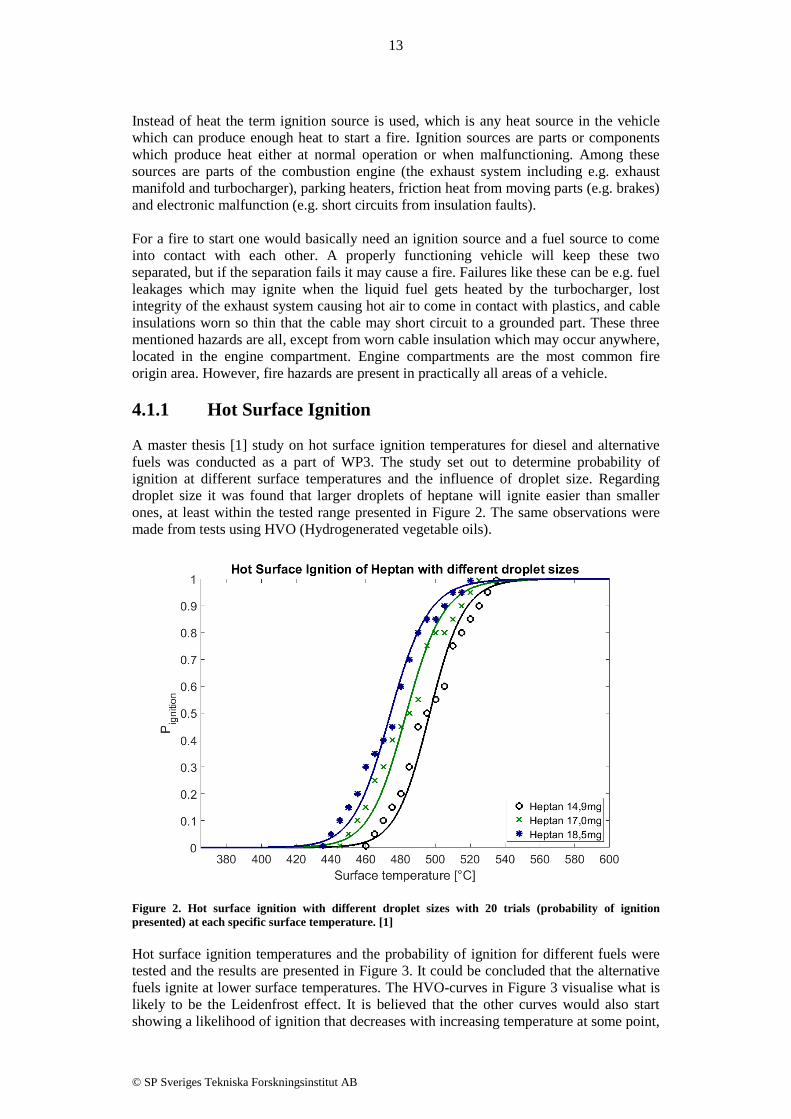
4.1.1 Hot Surface Ignition
A master thesis [1] study on hot surface ignition temperatures for diesel and alternative
fuels was conducted as a part of WP3. The study set out to determine probability of
ignition at different surface temperatures and the influence of droplet size. Regarding
droplet size it was found that larger droplets of heptane will ignite easier than smaller
ones, at least within the tested range presented in Figure 2. The same observations were
made from tests using HVO (Hydrogenerated vegetable oils).
Figure 2. Hot surface ignition with different droplet sizes with 20 trials (probability of ignition
presented) at each specific surface temperature. [1]
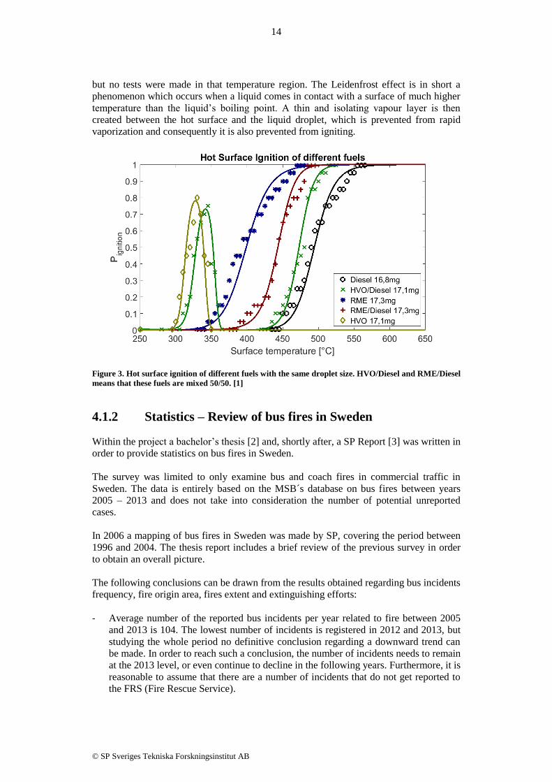
Hot surface ignition temperatures and the probability of ignition for different fuels were
tested and the results are presented in Figure 3. It could be concluded that the alternative
fuels ignite at lower surface temperatures. The HVO-curves in Figure 3 visualise what is
likely to be the Leidenfrost effect. It is believed that the other curves would also start
showing a likelihood of ignition that decreases with increasing temperature at some point,
14
© SP Sveriges Tekniska Forskningsinstitut AB
but no tests were made in that temperature region. The Leidenfrost effect is in short a
phenomenon which occurs when a liquid comes in contact with a surface of much higher
temperature than the liquid’s boiling point. A thin and isolating vapour layer is then
created between the hot surface and the liquid droplet, which is prevented from rapid
vaporization and consequently it is also prevented from igniting.
Figure 3. Hot surface ignition of different fuels with the same droplet size. HVO/Diesel and RME/Diesel
means that these fuels are mixed 50/50. [1]
4.1.2 Statistics – Review of bus fires in Sweden
Within the project a bachelor’s thesis [2] and, shortly after, a SP Report [3] was written in
order to provide statistics on bus fires in Sweden.
The survey was limited to only examine bus and coach fires in commercial traffic in
Sweden. The data is entirely based on the MSB´s database on bus fires between years
2005 – 2013 and does not take into consideration the number of potential unreported
cases.
In 2006 a mapping of bus fires in Sweden was made by SP, covering the period between
1996 and 2004. The thesis report includes a brief review of the previous survey in order
to obtain an overall picture.
The following conclusions can be drawn from the results obtained regarding bus incidents
frequency, fire origin area, fires extent and extinguishing efforts:
- Average number of the reported bus incidents per year related to fire between 2005
and 2013 is 104. The lowest number of incidents is registered in 2012 and 2013, but
studying the whole period no definitive conclusion regarding a downward trend can
be made. In order to reach such a conclusion, the number of incidents needs to remain
at the 2013 level, or even continue to decline in the following years. Furthermore, it is
reasonable to assume that there are a number of incidents that do not get reported to
the FRS (Fire Rescue Service).

15
© SP Sveriges Tekniska Forskningsinstitut AB
- Buses involved in incidents related to fire between 2005 and 2013 correspond to a
yearly average of 0.76% of the total bus fleet in commercial traffic. This figure
presents a general description of the reality. However, it does not reveal details about
the vehicles involved in the accident. To address this problem, the proposal is to link
the incident report to the Transportation Board's database of vehicle information. In
this way, all the relevant information on the vehicle involved in the incident, such as
the manufacturer, model, age, number of days in operation, distance travelled, fuel
type, etc., could be obtained and registered in the incident report simply by recording
the license plate number of the vehicle. This data could then be used in a more
specific way to draw conclusions regarding vehicles involved.
- Engine compartments are with 64% of the cases by far the most common origin area
for fire incidents on buses, and wheel well the second with 20% of the cases. To more
specifically identify the cause of fires requires processing of the data from other
sources; such as incident reports from the bus companies, bus manufacturers and
insurance companies.
- Total loss of the vehicle was the result in 7% of all recorded incidents between 2005
and 2013. In 49 % of registered total losses the fires originated in the engine
compartment, in the remaining 51% of cases the origin area was unknown. The
number of total losses varies during the studied period and there is no indication if the
trend is moving downward or upward. - FRS conducted action on average in 55% of call outs. The number of incidents which
have required extinguishing effort from FRS has been on a slightly downward trend
since 2006.
- Bus drivers have a significant role in the initial extinguishing effort. Bus driver (or
staff) extinguished the fire in 26 % of the occurred fire incidents between 2005 and
2013. Nevertheless, improvements can be made in bus drivers' education and training
in terms of more solid guidelines and skill requirements regarding fire safety issues.
Such an improvement could potentially lead to more bus fires being restricted or
eliminated prior to FRS arrival.
4.1.3 Statistics - Compilation of several studies
Statistics on fire causes are compiled from different studies performed in the U.S,
Australia, New Zealand, Finland and Sweden. The results are presented in bar graphs.
In Figure 4 statistics on fire causes from bus fires in Finland 2010-2011 is presented. The
most common cause is from electrical failure, closely followed by friction heat from
brakes or bearings.
In Australia the most common stated fire cause in buses between 2009 and 2013 was
mechanical failures in engine compartments followed by electrical failures in the engine
compartment, see Figure 5.
Between 1999 and 2003 bus and school bus fires in the U.S. were mainly caused by
mechanical failures. The second most common cause was electrical failures. The first
item most often ignited was electrical wire insulation followed by flammable liquids, see
Figure 6. Statistics from 120 bus fire investigations between 2002 and 2006 in the U.S.
illustrates what or who caused the failure which lead to the fire. The most common cause
was a random failure while a deficient design from the manufacturer and lack of skill
during maintenance was found to be second and third most common, see Figure 7.

16
© SP Sveriges Tekniska Forskningsinstitut AB
Another study from the U.S. concerning motorcoach fires between 1995-2008 identified
brakes and tyres as the most common ignition points with turbochargers being third most
common. Failed wheel or hub bearings was fourth most common and electrical failures in
the engine area was fifth, see Figure 8.
Figure 9 provides information on non-intentional automobile fires in the U.S. between
2006-2010 and shows in which area the fire started and also connects the origin to deaths
and injuries in the different accidents.
In Swedish underground mines electrical failures are the most common cause of fire
while mechanical failures also hold a fairly large proportion of the fire causes between
1988 and 2010, see Figure 10.
A study on vehicle fires in parking buildings from 1995-2003 in New Zealand, see Figure
11, show that disregarding deliberately lit fires or exterior fire causes from e.g. hot works
the electrical failures account for the majority of the fires while mechanical failures
including leaks are also quite commonly occurring. Note that while the fires took place in
parking buildings they have not exclusively started in parked, powered down vehicles.
Bus fires in Finland
Figure 4. Bus fires in 2010-2011 in Finland. Source: E. Kokki, Bus Fires in 2010-2011 in Finland, FIVE
2012, Chicago.
Bus fires in Australia
Figure 5. Reviewed Australian bus fire incidents between 2009 and 2013. Approximately 85 bus fire
incidents were reviewed, but detailed information on fire origin was only found on 27 incidents.
Source: Bus Industry Confederation Inc., Fire Mitigation Advisory, Australia, 2014.

17
© SP Sveriges Tekniska Forskningsinstitut AB
Bus fires in the US
Figure 6. U.S. bus and school bus fires, annual averages between 1999-2003. Upper diagram: Fire
causes. Lower diagram: Item first ignited. Source: M. Ahrens, Vehicle fires involving buses and school
buses, NFPA, US, 2006.
Bus fire responsibilities in the US
Figure 7. 120 bus fire investigations in US between 2002-2006. Diagram shows who was held
responsible. 89 of 120 fires are related to electrical and high pressure fluid line failures. Source: Public
Transportation Safety Board, Bus fire analysis – Investigations 2002 through 2006, US, 2008.

18
© SP Sveriges Tekniska Forskningsinstitut AB
Motorcoach fires in the US
Figure 8. Reported ignition points of motorcoach fires in the US between 1995-2008. Source: N. R.
Meltzer, G. Ayres and M. Truong, Motorcoach Fire Safety Analysis: The Causes, Frequency, and
Severity of Motorcoach Fires in the United States, FIVE 2012, Chicago.

19
© SP Sveriges Tekniska Forskningsinstitut AB
Automobile fires in the US
Figure 9. Non-intentional automobile fires in the US between 2006-2010. Statistics are based on about
450 000 reported automobile fire incidents, including cars, buses, trucks, etc. Source: M. Ahrens,
Automobile Fires in the U.S.: 2006-2010 Estimates, FIVE 2012, Chicago.

20
© SP Sveriges Tekniska Forskningsinstitut AB
Vehicle fires in Swedish underground mines
Figure 10. Vehicle fires in underground mines 1988-2010. Source: R. Hansen, Investigation on fire
causes and fire behaviour – Vehicle fires in underground mines in Sweden 1988-2010, Mälardalen
University, Sweden, 2013.
Vehicle parking fires in New Zealand
Figure 11. Vehicle fires in New Zealand parking buildings from 1995 to 2003. Source: Y. Li,
Assessment of Vehicle Fires in New Zealand Parking Buildings, University of Canterbury, New
Zealand, 2004.

21
© SP Sveriges Tekniska Forskningsinstitut AB
4.2 Risk analysis guidelines
The hazards identified in the previous sections are important input to what to focus on in
a risk analysis. The aim of the risk analysis procedure is to identify the locations of the
fire hazards in an engine compartment, determine the possible consequences from an
incident at those locations and decide how to install a fire detection system in order to
detect the fire. Depending on the environment of the hazard location and the nature of the
hazard the fire may stay limited in size, meaning less need of early detection, or grow
fast, meaning great need of early detection.
In this section a general procedure is presented followed by a few common hazards and
hazardous designs which should be controlled in a risk analysis. The work has also been
implemented in a new SP Method for risk management, “SP Method 5289 – Fire Risk
Management Procedure for Vehicles”.
The most important part is the hazard identification, but both the risk estimation and the
risk evaluation parts may provide useful information.
4.2.1 Hazard identification
The fire triangle was introduced in section 4.1 and it could basically be said that where
there is a possible interaction between fuel, ignition sources and oxygen there is a fire
hazard. The hazard identification process aims to first and foremost answer where this
could happen, when it could happen, how it could happen, but also why it can happen.
Identified fire hazards on old vehicles that have been used for some time generally
include hazards related to wear and tear. To determine fire causes are crucial for the
identification of similar fire hazards, but can be a complex work since there are often
several indirect or underlying causes beyond the primary cause. For instance, a primary
cause of fire could be a hot surface of the exhaust system igniting some combustibles. An
underlying cause could then be a fuel hose rupture, which in turn could be caused by
abrasion due to a loose attachment. This, in turn, could possibly be caused by faults
during the fitting of the attachment.
Determined fire causes may as well be used to identify the most important fire hazards by
examining the surrounding materials and determining fire spread and development
following ignition. It is important to not only consider where the first ignition could take
place, but also where the fire would start growing and how to design the fire protection.
Small fires are more difficult to detect than large ones and at the location of the ignition
the fire may stay undetectable for some detection systems even though the fire spreads to
a different location. Ventilation may e.g. blow glowing embers from the place of ignition,
e.g. the exhaust manifold, to a plastic component downstream and there it may ignite the
plastic materials. The environmental conditions in an engine compartment have huge
effects on both fire development and fire detection performance, therefore it is important
to consider e.g. the airflow around the identified hazards in order to know where the fire
detector should be placed for optimal performance.
Statistics and historical events should always be taken into consideration while
performing hazard identification to decide which areas are most in need of detection
coverage and rapid detection.

22
© SP Sveriges Tekniska Forskningsinstitut AB
Example of a hazard and its complexity During a fire investigation in 2014 the fire cause was found to be a burning ember blown
from a pocket at the muffler forward to the combustible materials above the front left
tyre, i.e. the mudguard. The pocket where the wood chips were accumulating was an
identified hazard and well protected with both a linear heat detector and five nozzles from
the suppression system directed towards the muffler and the pocket, see Figure 12.
Figure 12 The muffler with surface temperatures of several hundred degrees Celsius is obviously an
identified hazard and well protected.
While a fire is likely to ignite here and the accumulation of combustible wood chips is a
likely fire cause, the fire is not likely to grow very large here. It has to spread somewhere
else to grow and according to this fire investigation that is what happened, but not in the
sense that it grew here and spread due to the heat produced and by flames. It spread
because one or two of the glowing embers from the pocket in front of the muffler
followed the wind to land further in contact with the mudguard in front of the muffler and
that is where the fire started growing, see Figure 13. This area was more or less
unprotected; the fire detection system did not cover that area and the fire suppression had
no chance of extinguishing a fire in that area.
The pocket with
accummulated
wood chips.
Nozzles

23
© SP Sveriges Tekniska Forskningsinstitut AB
This example shows the need of not only identifying the locations where a fire is likely to
ignite, but also where it may spread to before it is detectable. It is important to take both
air movements and locations of combustible materials nearby an ignition source in
consideration when deciding how to install both a detection system and a suppression
system.
Figure 13 The muffler from Figure 12 is situated in the left in this picture whereas the fire started
growing above the tyre, where the mudguard has been consumed by the fire.
4.2.2 Risk estimation
Following the hazard identification, risks should be quantified by a risk estimation
method. There are several different methods that could be used, and most of them are
based on estimations of the likelihood and consequence of the identified hazardous
events. The objective is to quantify the risks in order for them to be sorted with respect to
priority and actions needed.
A method often used in the vehicle industry is Failure Mode and Effects Analysis
(FMEA). This method can also be applied for quantification of the vehicle fire risks. The
identified hazards (failure modes) are given risk priority numbers based on
quantifications of probability of occurrence, severity, and probability of detection failure.1
Each of the quantifications is made on a relative scale where a higher rating contributes to
a higher estimated risk priority number.
Fire severity can be quantified by estimating the potential consequences for the vehicle,
the driver and passengers, as well as to the surrounding environment. For example, the
location and type of fire could affect the fire growth rate, the extent of the fire, evacuation
time for the driver and passengers, and also the possibility to extinguish the fire.
The probability of occurrence can be estimated based on fire statistics, but also with
consideration to operational conditions for the specific vehicle. Operational conditions
include, but are not limited to:
1 Note that detection failure here means failure to notice e.g. an abrasion in the isolation of a
battery cable during an inspection. It has nothing to do with fire detection.

24
© SP Sveriges Tekniska Forskningsinstitut AB
Maintenance practices
Operating environment
Operator experience and human errors
Wear and tear and life cycle of components
Finally, the probability of detection failure can be estimated with consideration to the
means for detection available. For fire risk estimation with use of FMEA, detection do
not in this case include fire detection but only detection of the hazard that might result in
a fire. Means for detection can e.g. include maintenance and inspection routines, driver
routines and training, tyre pressure monitoring system, brake system high temperature
warning, etc. It should be noted that the rating should only be lowered if an early
detection would prevent the start of a fire.
4.2.3 Risk evaluation
When the fire risks are quantified as described above, they should be sorted to provide an
overview of the risk image. The risk evaluation aims to provide this overview and to
separate the risks which need to be specifically addressed from risks that are just subjects
to a basic level fire detection need.
The matrix in Figure 14 below could be used for guidance.
Figure 14. Fire risk assessment matrix.
Actions corresponding to the different risk ratings could be:
High/Serious – Rapid fire detection needed. System installation should consider
how to detect a fire immediately after or before ignition.
Medium – Relatively rapid fire detection needed. Fire should be detected before
it spreads to nearby areas.
Low – Unlikely to cause rapid fire growth or rapid spread of fire. Sufficiently
protected by a basic level of fire detection.

25
© SP Sveriges Tekniska Forskningsinstitut AB
4.3 Conclusions
A fire needs heat, fuel and oxygen. In an engine compartment oxygen is normally
sufficient. This means that what is critical to avoid fires is to keep fuel and heat separated.
The heat sources are parts of the exhaust system (from manifold and turbocharger and
further to the exhaust system), friction from moving parts (e.g. faulty brakes or other
mechanical failures), electronic failures (e.g. component failures, isolation faults). Sparks
may also be generated from e.g. alternators. Fuels sources are all combustible materials
(e.g. insulation materials, plastic parts, tubes, hoses, filters) and the flammable liquids
(oils, diesel).
To avoid fires fuel lines should be kept at one side of the engine and the exhaust system
on the other. Solid combustibles like plastic components should be kept at a safe distance
from hot surfaces. However, separation between heat sources and combustibles is not
always possible; cables have plastic isolation and brakes are of course close to the tyres.
The most common fire causes are electrical cables, mechanical failures, tyre or brake
failures, liquid fuel leaks on hot surfaces and electrical component failures.
In Sweden between 2005-2013 a yearly average of 0.76% of the total commercial bus
fleet were involved in fire related incidents. The most common area of origin was the
engine compartments (64%) and wheel wells (20%). Total losses occurred in 7% of the
recorded events and in 49% of the total losses the fire originated from the engine
compartments. The other 51% originated from “unknown” locations. In 26% of the fire
incidents the bus driver (or staff) extinguished the fires.
When it comes to risk analysis it was found important to not only concentrate on fire
causes, ignition sources and their locations, but to also consider the following fire
development, fire growth and spread. At locations were the fire likely will grow slowly
the need for early detection might be less, but at locations were the fire will grow rapidly
or where the risk of fire spread to critical components or to driver or passenger
compartments is big there is need for faster detection. Where the fire starts growing is
deemed to be just as important for detection systems as where it starts. It is important to
cover all aspects of fire causes when performing a risk analysis; risk designs, historical
fire causes, maintenance practices, operating environments and wear and tear and life
cycle of components.

26
© SP Sveriges Tekniska Forskningsinstitut AB
5 Fire detection systems for engine
compartments (WP4)
The purpose of WP4 was to test and evaluate relevant fire detection systems to determine
characteristics and advantages/disadvantages of the different systems. The tests were the
basis for defining of fire scenarios, test setups, test procedures and test requirements
implemented in the new test method developed in WP6.
The WP4-report included two parts: a technical description of fire detection technologies
commonly used in engine compartments or technologies that are relevant but not yet
implemented, and an overview of test results from tests performed to evaluate different
fire detection technologies.
5.1 Fire detection technologies
This chapter presents fire detection technologies that are either commonly used in engine
compartments or technologies that are relevant but not yet implemented or used
frequently in engine compartments of heavy vehicles. Provided is a technical description
and an understanding of how the different systems work.
5.1.1 Heat detection systems
Heat detection is today by far the most common way to detect fires in the engine
compartment of heavy vehicles. Both point heat detectors as well as linear heat detectors
are common and some technologies that are used are described below.
Point heat detectors Thermocouples are one technology that can be used to monitor the temperature. They
consist of two conductors of different material joined together at the point where the
temperature is to be measured. The voltage difference between the conductors in the other
end, positioned in a known reference temperature, will be proportional to the temperature
in the joint. This is based on the Seebeck effect which states that the gradient of voltage
in a conductor with no internal current flow is directly proportional to the gradient in
temperature [4]. The measured temperature can then be interpreted in different ways to
activate an alarm either on rate-of-rise of temperature or at a fixed temperature.
Also other technologies can be used to measure the temperature in a point. Thermometers
include several physical temperature phenomena that can be converted into a numerical
value e.g. thermal expansion of solids and liquids, pressure change of a gas, change of
resistance in a sensor (thermistor and resistance temperature detector, RTD), or infrared
radiation (IR thermometer and thermal imaging camera) [4]. Some of these physical
phenomena can also be used in a direct way without conversion to a numerical value and
monitoring of the temperature. For example, activation due to that a glass bulb breaks as a
result of the thermal expansion of the liquid inside the bulb is common in sprinklers but is
also used in detection systems. A similar technology to the breaking glass bulb is the
fusible link heat detector. Instead of a glass bulb that breaks at a fixed temperature the
fusible link heat detector make use of the melting point of an alloy. The melting of the
element breaks an electrical circuit causing the activation of an alarm or a sprinkler. [5]
Bimetal heat detectors make use of the thermal expansion of solids [4]. Two different
metals are joined together, and due to different coefficients of thermal expansion the
temperature change can be converted into mechanical displacement, see Figure 15. The
mechanical displacement can in turn activate an alarm.

27
© SP Sveriges Tekniska Forskningsinstitut AB
Figure 15. The principal of non-heated (left) and heated (right) bimetal. [6]
Linear heat detectors Linear heat detectors use a hose or cable to detect heat along the entire length of the
sensor. The different technologies are in many cases similar to what is used for point heat
detectors. For example, change of resistance in a conductor or pressure change of a gas in
a hose is widely used. Such detectors are often called “averaging linear heat detectors”,
which means that the detector makes no difference between a small temperature increase
over the entire length and a large increase at one point as long as the change of
resistance/pressure over the whole length is the same. In addition, the point of a large
temperature increase cannot be localized. However, these detectors have the ability to
monitor the temperature continuously and have the possibility to activate an alarm on
either rate-of-rise or at a fixed temperature.
Two of the most common linear heat detectors used in engine compartments of heavy
vehicles are based on polymer degradation and melting. In one of the two technologies
the sensor cable consists of two conductors, each insulated with a heat sensitive polymer.
The insulated conductors are protected by an outer jacket. At the activation temperature
the heat sensitive polymer melts and the conductors will short circuit, initiating an alarm.
The other common technology uses a pressurised hose which bursts at a specific
temperature. The main reason for the burst is degradation of the polymer, however, the
pressure in the hose will affect the temperature needed for the hose to break. When the
hose bursts the pressure in the system falls which activates an alarm. The system can
contain gas or liquid. Some manufacturers have opted to use liquid from experience that
liquid systems have less problems with leakages and unwanted pressure falls. This type of
activation can also be used directly on the suppression system, such that the suppression
agent is released when the hose bursts.
A technology that is used in e.g. the aviation industry, but to our knowledge has not been
used in engine compartments of heavy vehicles, is optical fibre heat detectors. A
temperature rise in one part of the optical fibre will change the refraction and scatter
properties. Change in refraction will be registered by a sensor in one end of the optical
fibre due to changes of the back-scattered light in the fibre. The position where the
temperature increase of the optical fibre occurs can be determined by measuring the time
of a light pulse to go back and forth to the point of refraction change (a portion of the
light pulse will be back-scattered at this point). This type of systems can initiate an alarm
either on rate-of-rise conditions or fixed temperature conditions. [7, 8]
5.1.2 Flame detection systems
In engine compartments of heavy duty vehicles flame detectors are sometimes used as a
complement to heat detectors, but could also be used alone if they are designed for that
purpose. The reason to complement the fire detection system with flame detectors is to

28
© SP Sveriges Tekniska Forskningsinstitut AB
get a very fast response in case of fast developing flaming fires, e.g. ignition of a ruptured
fuel line.
Flame detectors react on the electromagnetic radiation from flames, which include the
infrared (IR) spectrum, visual light, and the ultraviolet (UV) spectrum. Most flame
detectors are constructed to detect radiation at several different narrow or wide
wavelength regions to avoid false alarms. It can be a combination of IR and UV regions
or just different regions in the IR spectrum. For example, in fires there is a lot of radiation
at wavelengths around 4.3 µm due to molecular vibration of carbon dioxide, which is a
fire product. The relationship between radiation at this wavelength and other wavelengths
is then often different for fires compared to other hot objects and other potential sources
for false alarms. [9, 10]
False alarms may also be avoided by looking at the fluctuation of radiation. The
fluctuation frequency at a specific wavelength could be very different for a flame
compared to other radiation sources.
A third way to avoid false alarms is to let the detector compensate for small and slow
changes in radiation. For example, increased heat radiation from the turbocharger will be
neglected, but a large and sudden flame will generate an alarm. The drawback of these
detectors is that they will be insensitive to slow-growing fires.
Flame detectors can either use thermal sensors or photonic sensors. A common thermal
sensor is the pyroelectric sensor, which generates a temporary voltage when heated or
cooled. This type of sensor can be used to detect fluctuations or large changes in the IR
radiation spectra. To measure constant levels of radiation and radiation in the UV region
semiconductor photodiodes are often used. These sensors convert incident photons into
charge carriers. Photonic sensors are often associated with higher sensitivity and faster
response compared to thermal sensors, but to a higher cost and in some cases less
robustness. [11]
Since a flame detector must “see” the flames it is important that the detector lens is not
obscured by dirt, ice, and oil. Different wavelength regions will be affected more or less
by the different contamination products [9]. Some detectors also have the ability of lens
supervision and will generate a warning signal if the lens is obscured more than
acceptable.
5.1.3 Smoke/gas detection systems
Smoke and gas fire detection has not been considered for engine compartments of heavy
vehicles in the past due to the harsh environmental conditions and high risk of false
alarms. The Vulcan project [12] has modified this previous view on smoke detection
systems and there are now other market players showing interest in this. The benefit of
smoke and gas detection is very early warning in case of smouldering fires and slow-
growing fires, characteristic to electrical fires.
Smoke and gas detection systems can either be of point type or aspirating type. Aspirating
detectors use a sampling pipe network to draw air from one or several points through the
pipe network to the detector unit. The benefits of using aspirating systems are that the
detector can be placed outside the harsh environment of the engine compartment and that
one sensor can cover more than one point in space. Furthermore, it is easier to apply
filters, which clean the air from particles not characteristic for fire smoke. [13]
For household applications both ionisation smoke detectors and photoelectric smoke
detectors are used, but detector suppliers to the vehicle industry and aspirating smoke

29
© SP Sveriges Tekniska Forskningsinstitut AB
detector system suppliers use almost exclusively the photoelectric principle. These
detectors have a light source and a photo detector in the smoke chamber to either register
light scattered by the smoke particles or light obscured by the smoke particles.
Filters, drift compensation, dual wavelengths and photodiodes at multiple scattering
angles are examples of methods used to avoid false alarms in smoke detectors. Several
wavelengths and scattering angles are used to determine particle size and drift
compensation is used to compensate for dust and dirt or aging of the optical components.
Most detectors have a warning system to alert the user if the detector is unable to
compensate anymore or if the filter is clogged.
There are several different types of gas detectors that are used for various applications
[10]. One interesting technology that is used in other harsh environments, e.g. in tunnels
and coal mines, is called electronic nose. It uses several semiconductor sensors to “smell”
different gases. The relative concentrations between the different gases give patterns such
that the detector recognises if the “smell” is from combustible gases, an actual fire or
from a false alarm source. [14]
5.2 Detector performance
Tests were performed in WP4 to evaluate different fire detection technologies and to
develop the new test method (WP6). Between the tests with different suppliers and
different fire detection systems the test configuration was changed to implement new
ideas and experience from earlier tests. This is a natural part of developing a test method.
It also means that a precise comparison between different types of fire detectors cannot be
presented. However, in the future the completed test method will be an accurate and
repeatable basis for comparative tests between different fire detection systems applicable
for engine compartments of heavy vehicles.
Presented below are an overview of test setups and a summary of test results for different
types of detection technologies. Heat, flame and smoke detectors were tested, but not gas
detectors.
5.2.1 Heat detectors
Several different heat detectors were tested in a heat tunnel to determine activation
temperature and response times. The heat tunnel used can be seen in Figure 16. The
airflow velocity could be altered up to approximately 2.5 m/s. Most tests were conducted
in 1.5 m/s with a constant air flow, but in some tests the mass flow was held constant
which means that the velocity increased with increased temperature. However, no
distinctive differences were obtained for air flow velocities varying from 1.5-2.5 m/s.
Detectors were mounted in different ways (the tunnel was not adapted for a good
mounting of linear detectors) and the number of performed tests varied between products,
but an approximate comparison of the response time of some different detectors are
shown in Table 1. The response time is measured by plunging the detector into a hot
tunnel, kept at a specific temperature above the detector’s activation temperature, and
noting the time interval between the plunge and activation of the detector. The activation
temperature is determined by a slow temperature ramp, 1 °C/min, with the detector
mounted in the tunnel. The activation temperatures measured in the heat tunnel were
always higher than listed for the product. One reason could be that the listed activation
temperatures are specified in an oven with a slower temperature ramp. The response
times varied a lot between detectors and for temperatures close to the activation
temperature the response times were in general several minutes. For higher temperatures
the response times are shorter and the variance between detectors is less significant.

30
© SP Sveriges Tekniska Forskningsinstitut AB
Figure 16. Heat tunnel.
Table 1. Activation temperatures and response times of some different detectors tested in a heat tunnel.
Detector type Activation
temp.
Response time in plunge
test approx. 10°C above
activation temp.
Response time in
plunge test 30-50 °C
above activation temp.
Det. 1 (point) 130-150 °C
(diff. covers) 4-7 min 2-4 min
Det. 2 (point) 70 °C ~ 1 min ~ 45 s
Det. 3 (point) 140 °C ~ 6 min ~ 30 s
Det. 4 (linear) 190 °C 4-8 min 1.5-4 min
Det. 5 (linear,
averaging)
280 °C (10 cm)
180 °C (170 cm) 1-2 min 30-50 s
Heat detectors have also been tested for false alarms against a hot surface. In the test a
metal plate was heated by a LPG burner, see Figure 17. A thermocouple was soldered on
to the other side of the plate to measure the surface temperature and the detector was
positioned at different distances from the hot surface. The temperature of the surface was
kept at around 600-650 °C.
Two detectors (det. 3 and det. 5) were highly resistant to this type of false alarm. Shortest
distance tested was 5 cm and there were no activation within about 15 min. Most other
detectors had to be at least 15 cm away from the surface to not generate an alarm.
All detectors have also been tested in real fire scenarios either in a realistic engine
compartment mock-up, as seen in Figure 18, or in simpler setups as seen in Figure 19.
Size of fire, fuel composition, airflow, distance to detectors and positions of detectors,
either above the fire or beside, have been altered in the tests. Also different kinds of
obstructions have been used.

31
© SP Sveriges Tekniska Forskningsinstitut AB
Figure 17. Metal plate heated by a LPG burner for false alarm tests.
The general conclusion from the real fire scenarios is that heat detection is uncertain to
occur unless the flames impinge directly on the sensor. Detectors positioned above the
fire or where the smoke accumulates could generate an alarm if there was minimal air
movement, but with some airflow ventilating and diluting the hot fire gases detection did
not occur. The tests also showed that activation due to heat radiation from the flames was
hard to achieve, since detectors could be positioned very close alongside the flames
without initiating an alarm, however, heat detectors are generally not designed for
detection of solely heat radiation. Most fires used in the tests were small fires below 50
kW, but some fires up to 100 kW were also used. Larger fires will produce more heat and
consequently be easier to detect. Also the surrounding temperature, which could be much
higher than in the tests performed, affects the response time. At last, obstructions affected
heat detection by preventing the flames to impinge on the sensor.
Figure 18. Heat detector fire test in an engine compartment mock-up.
32
© SP Sveriges Tekniska Forskningsinstitut AB
Figure 19. Heat detector fire test.
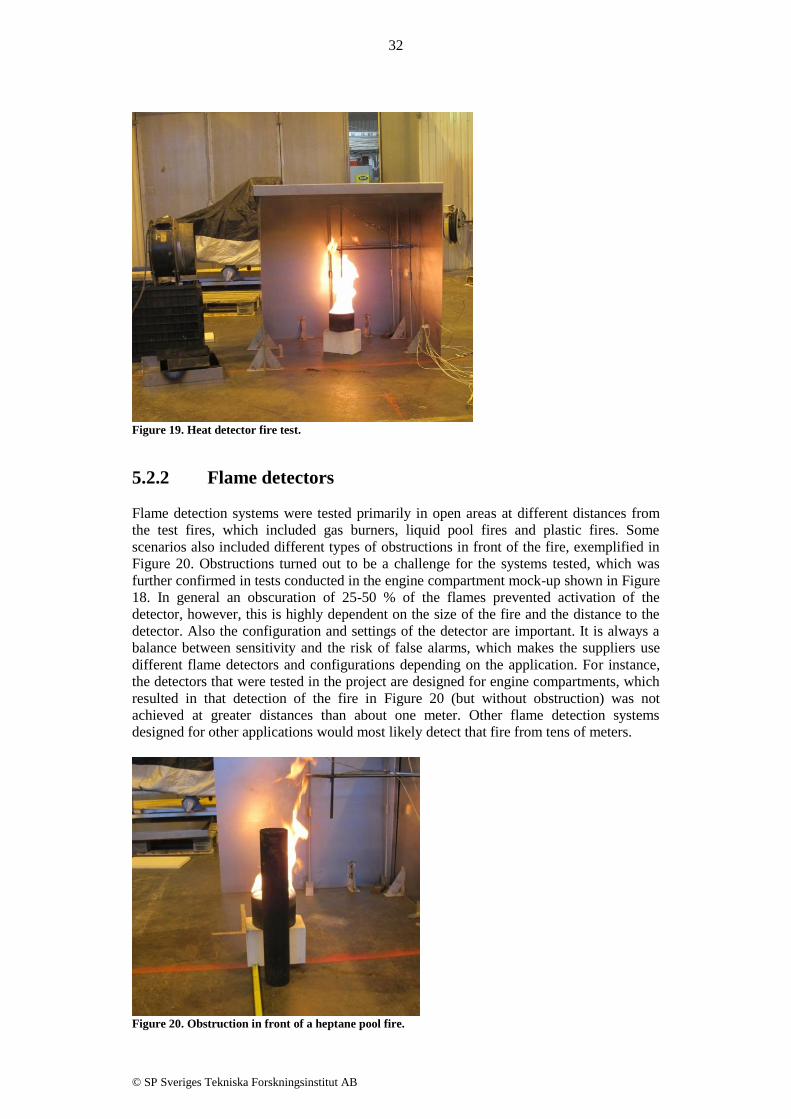
5.2.2 Flame detectors
Flame detection systems were tested primarily in open areas at different distances from
the test fires, which included gas burners, liquid pool fires and plastic fires. Some
scenarios also included different types of obstructions in front of the fire, exemplified in
Figure 20. Obstructions turned out to be a challenge for the systems tested, which was
further confirmed in tests conducted in the engine compartment mock-up shown in Figure
18. In general an obscuration of 25-50 % of the flames prevented activation of the
detector, however, this is highly dependent on the size of the fire and the distance to the
detector. Also the configuration and settings of the detector are important. It is always a
balance between sensitivity and the risk of false alarms, which makes the suppliers use
different flame detectors and configurations depending on the application. For instance,
the detectors that were tested in the project are designed for engine compartments, which
resulted in that detection of the fire in Figure 20 (but without obstruction) was not
achieved at greater distances than about one meter. Other flame detection systems
designed for other applications would most likely detect that fire from tens of meters.
Figure 20. Obstruction in front of a heptane pool fire.

33
© SP Sveriges Tekniska Forskningsinstitut AB
The detectors’ field of view were tested, and varied between 30-60 degrees depending on
distance to fire and size of fire. The projected area of the sensor facing the fire will be
smaller if the detector is rotated away from the fire, decreasing the amount of radiation
absorbed. Up to 30° rotation, the reduction of detection capability will be quite small, but
a rotation angle above 60° generally reduce the detection capability by more than 50%,
meaning that the detector has to be less than half the original distance to the fire.
The propensity of false alarms was tested by exposure to a hot surface and welding. In
general, this will not initiate any alarms. Flame detectors are often configured to be
sensitive to several different wavelength regions and use the relationship between these
regions to differentiate between actual fires and radiation sources considered as false
alarms. However, some flame detectors will give an alarm if the change of radiation is
great enough, which means that an alarm can be generated if the radiation source is
concealed and then suddenly disclosed. Further, this feature can make the detectors
irresponsive to slow-growing fires due to that the radiation is compensated for as if it was
changes in the background, such as the heating of a hot surface.
5.2.3 Smoke detectors
Smoke detectors are still uncommon for vehicle engine compartment applications and
only one aspirating smoke detection system was tested in the engine compartment
mock-up. The system performed well, also for high airflows, which is the greatest
challenge for detection of smoke. Several different fuels were tested, including plastics,
cables, diesel, heptane and E85. E85, producing significantly less smoke, was the only
one creating some problems. Notable is that the response time of the detector was not
decreased for significantly higher fire loads and rates of smoke produced, indicating that
the main contributors to the response time of the detector to be the sampling time and/or
the algorithm processing time.
The main issue for smoke detectors has historically been the harsh and dirty environment
of an engine compartment. However, this can be managed and tests where smoke
detection systems have been installed in different vehicles show that false alarms can be
avoided. However, it still poses a challenge and may require shorter service intervals
depending on the type of vehicle and environment it is operating in.
5.3 Conclusions
Fire detection systems for vehicle engine compartments use almost exclusively heat as
criteria for fire detection today. Both point and linear heat detectors are common and
there are several different technologies used. Heat detectors are generally much cheaper
than flame and smoke/gas detectors, and provide in general a high level of robustness. As
an example of the robustness; dirt and dust rarely have as much impact on heat detectors
as for other technologies. Another advantage is that they can be very simple and e.g. not
include any electronic circuits at all for activation of the suppression system (see section
5.1.1 above). However, the high ambient temperatures and the airflows in engine
compartments put heat detection to a challenge. In general, the flames have to be very
close or impinge on the sensor for the fire to be detected. For that aspect, linear detectors
have an advantage over point detectors by the coverage of more points in space.
If flame detectors are used they are often used as a complement to heat detection and
designed for fast response in case of a spray fire or a large pool fire. The response time is
often less than one second if the fire is in line of sight of the detector and sufficiently
large. However, obstructions are a challenge and can prevent detection if the fire is not

34
© SP Sveriges Tekniska Forskningsinstitut AB
large enough. In addition, slow-growing fires are sometimes not detected at all. Flame
detectors are not affected by airflow, but can get obscured by dust and dirt on the detector
lens.
Smoke/gas detectors have the unique ability to detect smouldering fires and slow growing
fires at an early stage. Moreover, the coverage of an engine compartment is more easily
obtained compared to heat detectors. However, dirt, dust and exhaust can generate false
alarms and the detectors may require shorter service intervals.

35
© SP Sveriges Tekniska Forskningsinstitut AB
6 Fire detection in bus and coach toilet
compartments and driver sleeping
compartments (WP5)
The purpose of WP5 was to provide recommendations on what type of fire detection
system that should be used and how these systems should be installed in bus and coach
toilet compartments and driver sleeping compartments. In July 2014 a new UNECE
requirement came into effect which states that excess temperature or smoke shall be
detected in these compartments [15]. Therefore, this work provided timely information on
the installation of fire detection systems in toilet compartments and driver sleeping
compartments.
The work of WP5 and the installation recommendations have been published in
SP Report 2014:28 “Fire detection & fire alarm systems in heavy duty vehicles : WP5 –
Fire detection in bus and coach toilet compartments and driver sleeping compartments”.
The main results and considerations have also been published as a peer-reviewed article
in Case Studies in Fire Safety [16]. The recommendations are mainly based on full scale
fire tests performed in mock-ups of a bus toilet compartment and driver sleeping
compartment. A total of 26 different buses and coaches from a variety of suppliers were
investigated to obtain input for the construction of realistic mock-ups. Five different fire
detection systems were tested: a linear heat detector, a point smoke detector, a point
smoke/heat detector, an aspirating smoke/heat detector, and another aspirating smoke
detector. These detectors were placed at several different positions in the mock-ups to
evaluate how such detectors are best installed. The detectors were exposed to different
fire scenarios and different fire sources were used such as: paper hand towels in the trash
can, plastics and rubber representing fire in electrical components and cables, and a
mattress in the sleeping compartment. In total 18 different full scale fire tests were
performed.
The luggage compartment is not explicitly mentioned in the new UNECE requirement,
but it is recommended to put detectors there also. In the luggage compartment a wide
variety of potential fire sources could be present. From the study it appears that air
velocities up to 10 m/s are not uncommon in air streams in the luggage compartment,
which makes it important to examine detectors placement based on specific air flows.
The most interesting finding in this work was the large impact of the ventilation fan
inside bus toilet compartments. In several fire scenarios the impact of the fan was so great
that a fire detector in the ceiling of the toilet compartment would not give a fire alarm in
the early stage of a fire.
6.1 Conclusions
Smoke detectors are generally much faster than heat detectors, which is the case in all
tests presented in the WP5-report. In the presented tests the fires have developed quite
rapidly, but for slow growing fires the benefit of smoke detectors compared to heat
detectors would be even greater. However, there are locations where heat detection may
be considered, e.g. in the concealed space under the sink in toilet compartments or close
to the trash can where the detector is expected to be in the immediate vicinity of the fire.
In very narrow spaces and in other circumstances when the detector is close to the
potential fire source heat detectors will also react relatively quickly, although smoke
detectors will most often still be faster. The benefits of using heat detectors in these

36
© SP Sveriges Tekniska Forskningsinstitut AB
spaces are that they are usually cheaper and more robust. They may also require less
maintenance and inspection than smoke detectors.
In toilet compartments it is common to install a smoke detector in the ceiling, but the tests
clearly showed that with an operating fan it could be difficult to detect a trash can fire or
cable fire solely with a smoke detector in the ceiling (see SP Report 2014:28 for details of
the layout and air flow conditions). However, the fan may be malfunctioning resulting in
the smoke being transported upwards and not into the concealed space under the sink
where normally the fan is located. In such cases a detector in the concealed space would
be of limited use while a detector in the ceiling would be more effective. There might also
be other fire scenarios than those tested in this work. Therefore a detector in the ceiling is
useful as a part of an integrated detector system. The recommended requirement based on
the work presented in the WP5-report is that the detection system should consist of at
least a smoke detector in the ceiling and heat or smoke detector in the concealed space of
the fan, especially if this space also contains the trash can. For instance, in toilet
compartments of airplanes they use heat detection together with an extinguishing bottle
above the trash can as a complement to smoke detection in the ceiling. The suppression
occurs in this case only locally inside the waste bin.
If smoke detectors are used in many spaces the use of aspirating systems should be
considered instead of point smoke detectors. The benefit of this approach is that only one
detector is needed and the system samples air from e.g. both the ceiling and other spaces
in the toilet compartment. More advanced aspirating systems could potentially also
sample air from different locations around the entire bus. An aspirating smoke detector
positioned e.g. in the toilet compartment ceiling also has a great advantage in that the
detector is hidden and protected. According to the bus operators they have problems with
passengers pulling down the detectors, and not even a protective cage around the detector
is necessarily sufficient to protect against tampering. In particular it has been noted that
smokers are prone to tamper with detectors in toilet compartments. This further supports
the use of aspirating systems where the detector is hidden.
It is important to consider whether cigarette smoke should result in a fire alarm or not.
Most of the detectors tested did not respond to cigarette smoke, which is at least partly
due to the fact that these detectors are designed to have a high resistance to false alarms.
In the cigarette smoke scenario, this implies that the obscuration from the cigarette smoke
was too low for detection. A cheaper and simpler detector may be more sensitive to
cigarette smoke, but could also be more sensitive to e.g. dust. An emergency evacuation
on a highway, because of a smoker, induces other risks which should also be taken into
account when considering whether the detection system should detect cigarette smoke or
not.
Another important design consideration when installing detectors in the toilet
compartment ceiling is the need to avoid the air flow from the air inlet. The tests have
shown that the detection time may be delayed considerably with the detector positioned in
the inlet air flow, up to half a minute in these tests. This difference may be even larger for
slow-growing fires.
The tests in the sleeping compartment showed good circulation and fast smoke spread
inside the compartment. The time difference between having the detector close to the fire
or at the opposite end of the compartment was quite small. However, the results indicate
that the detectors should be placed near the ceiling. In addition, the mattress fire source
was analysed regarding toxic elements in the fumes. The results showed that the time of
evacuation from the activation of a fire alarm until the conditions are immediately
dangerous to life and health inside the compartment is approximately 30-60 seconds.
However, the response times of the detectors varies depending on position and type.

37
© SP Sveriges Tekniska Forskningsinstitut AB
Some of the full scale fire tests were also simulated in FDS (Fire Dynamic Simulator).
The results showed that computer simulations may be used for detector placement
guidance in these kinds of compartments. For complex geometries this tool may be
effective for evaluation of where to position the detectors.

38
© SP Sveriges Tekniska Forskningsinstitut AB
7 Development of international standard
(WP6)
The purpose of WP6 was to develop a new test method for fire detection in engine
compartments of heavy vehicles that can be implemented as an international standard.
This was done on the basis of the information gained throughout the project, such as
information of other standards and research in the area (WP1), knowledge of the
characteristics and the harsh environment of engine compartments (WP2), knowledge of
fire causes, fire scenarios and fire conditions possible in engine compartments (WP3), as
well as experience of how detection systems performed in tests and evaluation of
different test setups and test scenarios (WP4).
The test method has been published as SP Method 5320 “Test method for fire detection
systems installed in engine compartments of heavy vehicles”. The method includes
detection performance tests as well as system durability tests. There are two general
performance tests conducted in a standardised enclosure with typical engine compartment
characteristics; a “system coverage test” and a “response time test”. In addition, heat
sensors, flame sensors and smoke/gas sensors are tested separately for activation
temperature/sensitivity, false alarm (heat sensors only) and field of view (flame sensors
only). The durability tests evaluate the ability of the detector system to withstand
corrosion, ageing, temperature variations, vibrations, shocks, electromagnetic interference
and intrusion of water and dust.
7.1 Detection performance tests
To ensure the performance and the capability of a fire detection system a few different
tests were developed and evaluated. The final version is published in SP Method 5320
and the choices of fire tests and methods are motivated below.
7.1.1 System coverage test
The system coverage test is designed to ensure that the detection system has the ability to
detect fires starting in practically every possible location of an engine compartment. The
test apparatus, the test fires and their locations were chosen to be the same ones as used in
SP Method 4912, in which suppression systems for engine compartments of sizes 2-6 m³
are tested in a test rig with a gross volume of 4 m³.
The system coverage test is performed using a total of 13 test fire locations in an
environment which holds the same aggravating factors that could be expected of an
engine compartment. There is forced air flow through the test apparatus and obstructions
simulating e.g. an engine block which both affects detection performance and restricts
installation possibilities.
For real applications, it may be argued that one knows the locations of the fire hazards
and hence knows where to place the detector to cover the ignition points, but, as covered
in WP3, where the fire starts may not be where it grows and reaches a detectable size.
Therefore the system should be installed to cover a large enough area or space in order to
have a fair chance of detecting a fire at an early stage. The system coverage test is
designed to achieve this.

39
© SP Sveriges Tekniska Forskningsinstitut AB
7.1.2 Response time test
This test is mainly constructed to provide information and to compare the response times
of different detection systems to two different fire scenarios; a slow-growing fire and an
instant large flaming fire. The requirements assure that a detection system must consist of
detectors which by themselves, or combined with other detector types, can detect both
slow-growing fires and, with a short response time, instantly large flaming fires.
The slow-growing fire used in the test method is produced from a LPG-burner which
starts at 0 kW and steadily grows with 3 kW per minute. The instant large flaming fire is
represented by a pool fire using a heptane/diesel fuel mixture.
7.1.3 Heat detection
The activation temperature/response time of heat detectors is determined in a heat tunnel
and is of an informative nature; there will be no requirements for at which temperature or
rate-of-rise of temperature a detector should activate. There will, however, be
requirements on consistency before and after the durability tests.
Heat detectors will also be subjected to a test designed to rate the false alarm sensitivity
due to hot surfaces. Detectors will be placed at different distances away from a hot metal
surface and depending on the how close to the surface they can be mounted without
generating an alarm they will receive ratings of high, medium or low resistance. The
rating is purely informative and is to be used as a guideline on where to install heat
detectors without producing false alarms.
7.1.4 Flame detection
Flame detectors will be tested to determine their sensitivity. A LPG-burner will be used to
produce fires with different heat release rates. The fire will be hidden behind a screen and
suddenly be exposed when the test starts. The lowest heat release rate at which the flame
detector activates an alarm is documented and used as a comparative value for the
verification test following the durability tests.
Flame detectors will also be subjected to field-of-view tests. The heat release rate from
the test fire in the sensitivity test is increased by 50% and the detector is rotated vertically
and horizontally to determine its field-of-view. This test provides important information
for the installation of the system as the sensor will have difficulties to detect fires outside
its field-of-view.
Since a flame detector heavily relies on visibility to detect a fire it is important that the
lens is kept clear. It is therefore required that the system has an integrated lens
supervision to supply a warning signal if the lens is too obscured by e.g. dirt from the
engine compartment.
7.1.5 Smoke/gas detection
The sensitivity of smoke- or gas detectors is determined in a smoke tunnel through which
the smoke from heated wood sticks is transported. Time to activation and obscuration
level at activation is documented to be compared with the verification test after the
durability tests.
Smoke/gas detectors rely on the smoke/gas reaching the sensing chamber. It is also
important that the sensing chamber in the detector is not contaminated. Therefore it is

40
© SP Sveriges Tekniska Forskningsinstitut AB
required that smoke/gas detectors are equipped with sensing chamber supervision which
shall trigger a warning signal if the chamber is contaminated. It is also required that the
detectors use filters, both to avoid false alarms and contamination of the sensing chamber.
If the filter is not visible from the outside the detector shall trigger a warning signal if the
filter becomes clogged.
7.2 Detection system durability tests
An engine compartment provides a harsh environment for any component installed in it.
The temperature is often in the areas around 100 °C and at hot spots it could be
considerably warmer. There is water splashing from the road and during the winter
months in cold climates there will be road salt added to that. Vibrations from the engine
and the ground will also affect the detection system and temperature changes from cold to
warm including humidity changes could potentially also cause problems. Further, there is
normally a lot of dirt entering the engine compartment which could greatly affect some
detection systems. It is important that a fire detection system is durable enough to
withstand the environmental factors affecting it without reducing sensitivity or
functionality.
Therefore a few different durability tests are included in the test method. The factors
which were found to be most important were corrosion, ageing, temperature variations,
vibrations and mechanical shock, electromagnetic compatibility (EMC) and ingress from
particles and water (IP-classification).
For EMC and IP-classification the test method refers to UNECE Regulation No.10 and
ISO 20653:2013 respectively. The detection system should live up to the requirements in
UNECE Regulation No. 10 and the lowest allowed IP-classification is IP652.
7.2.1 Corrosion
In order to ensure that the detection system withstand the corrosive effects of salt and
atmospheric pollutants the system will be subjected to a 3 week exposure in accordance
with test method B in ISO 21207.
Following the corrosion test the detection system shall be subjected to the activation
temperature or the sensitivity tests related to the specific detector type. It is required to
produce a similar result compared to not being subjected to the corrosion test.
7.2.2 Ageing
The system is subjected to an ageing test using both relevant agents that is likely to come
in contact with it, e.g. engine oil and vehicle washing chemicals, and a subsequent
elevated temperature test (accelerated ageing).
The reason to include both a test for chemical liquid exposure, in accordance with ISO
16750-5:2010, and an elevated temperature test, using the procedure described in chapter
5.13 in ISO 6722-1, is that polymers age differently and are affected both by heat,
humidity and different chemicals. It was found important to include the tests using the
most common factors which could affect the detection system.
2 IP65 is only allowed if it is accompanied with a specification that the detection system cannot be
pressure washed. Otherwise the system should be classified towards IP6K6K/IP6K9K.

41
© SP Sveriges Tekniska Forskningsinstitut AB
Following the ageing test the detection system shall be subjected to the activation
temperature or the sensitivity tests related to the specific detector type. It is required to
produce a similar result compared to not being subjected to the ageing test.
7.2.3 Vibrations, temperature variations and mechanical
shock
In order to ensure that the detection systems endure the mechanical stress from vibrations
they will be tested against Test VII (Commercial vehicle, sprung masses) in ISO 16750-
3:2013 with a temperature cycle either based on the specifications on operating
temperatures of the detection system or between -40 °C and 100 °C.
Following the combined vibration and temperature cycling test the detection system shall
be subjected to a mechanical shock test in accordance with Chapter 4.2.2 in ISO 16750-
3:2013. It is supposed to simulate larger impacts from e.g. curb stones, a hole or perhaps
a small collision. For systems intended to be installed in off-road vehicles additional
shock tests are required.
Following the vibration, temperature cycling and shock tests the detection systems shall
be subjected to the activation temperature or the sensitivity tests related to the specific
detector type. It is required to produce a similar result compared to not being subjected to
the durability tests.
7.3 Conclusions
SP Method 5320, a test method for fire detection systems installed in engine
compartments of heavy vehicles, evaluates performance and durability of the detection
system. Fire detection systems tested in accordance with SP Method 5320 can obtain the
P-mark, the quality mark of SP approved products, if certification rules SPCR 197 is
fulfilled.
In the certification rules, also developed in connection to WP6, an additional requirement
in form of a risk assessment is included. The purpose for this is to adapt the installation of
the system to the specific engine compartment in terms of specific fire hazards and the
prevailing environmental conditions. Air flow, obstructions, fire loads etc. shall be
accounted for and thus contribute to ensure that the system design has the ability to cover
the identified fire hazards and achieve fast detection regardless of where in the engine
compartment the fire originates.
For buses and coaches, SP Method 5320 will complement SP Method 4912 to include
both fire detection and fire suppression in the P-mark certification of fire safety systems.
As previously done for fire suppression, where parts of SP Method 4912 have been
implemented in the European legislation for buses, through UNECE Regulation 107, also
parts of SP Method 5320 will form the basis for a proposal of new requirements for fire
detection to be implemented in UNECE Regulation 107.

42
© SP Sveriges Tekniska Forskningsinstitut AB
References
[1] D. Henningsson, ”Hot Surface Ignition of Several Alternative Fuels,” Luleå
University of Technology, Luleå, 2015.
[2] A. Rakovic, ”Bus Fires in Sweden 2005 - 2013: Frequency, Origin Area, Fire Extent
and Extinguishing Efforts,” Luleå University of Technology, Luleå, 2014.
[3] A. Rakovic, M. Försth och J. Brandt, ”Bus fires in Sweden 2005 - 2013,” SP
Technical Research Institute of Sweden, Borås, 2015.
[4] A. Andersson, Mätteknik för processindustrin, Borås: SP Technical Research
Institute of Sweden, ISBN: 978-91-86319-82-3, 2012.
[5] V. K. Jain, Fire Safety in Building, Delhi, India: New Age International (P) Ltd.,
Publishers, 1996.
[6] “Bimetal,” [Online]. Available: https://en.wikipedia.org/wiki/Bimetal. [Accessed 29
January 2016].
[7] Protectowire, “Fiber Optic Linear Heat Detection for Special Hazard Applications,”
[Online]. Available: http://protectowire.com/documents/FiberSystem8000-
Brochure.pdf. [Accessed 29 January 2016].
[8] Z. G. Liu, G. Crampton, A. Kashef, G. Lougheed, E. Gibbs, J. Z. Su and N.
Benichou, “International Road Tunnel Fire Detection Research Project - Phase II,”
National Research Council of Canada, Ottawa, Canada, 2008.
[9] S. E. Hodges and G. D. Simpson, “Effective Technologies for Fire Sensing and
Suppression on Transit Vehicles,” APTA 1995 Bus Operations and Technology
Conference, 1995.
[10] D. Nilsson and G. Holmstedt, “Kompendium i Aktiva system - Detektion,”
Department of Fire Safety Engineering, Lund University, Sweden, 2007.
[11] A. Rogalski, “Infrared detectors: an overview,” Infrared Physics & Technology, no.
43, pp. 187-210, 2002.
[12] European Commission, “VULCAN Result In Brief,” [Online]. Available:
http://cordis.europa.eu/result/rcn/165052_en.html. [Accessed 29 January 2016].
[13] J. Rönnblom, J. Brandt and M. Försth, “Fire Detection in Engine Compartments of
Buses,” SP Technical Research Institute of Sweden, SP Report 2012:54, 2012.
[14] Firefly AB, “Early fire detection with the Electronic Nose (MGD),” [Online].
Available: http://www.firefly.se/en/solutions/electronic-nose. [Accessed 24 August
2015].
[15] UNECE Regulation No. 107 - Rev. 3 - Amend. 4, “General construction of buses
and coaches,” 2012.
[16] O. Willstrand, J. Brandt and R. Svensson, “Detection of fires in the toilet
compartment and driver sleeping compartment of buses and coaches - installation
considerations based on full scale tests,” Case Studies in Fire Safety, vol. 5, pp. 1-10,
2015.

SP Technical Research Institute of Sweden
Box 857, SE-501 15 BORÅS, SWEDEN
Telephone: +46 10 516 50 00, Telefax: +46 33 13 55 02
E-mail: [email protected], Internet: www.sp.se
www.sp.se
Safety – Fire Research
SP Report 2016:85
ISBN 978-91-88349-73-6
ISSN 0284-5172
More information about publications published by SP:
www.sp.se/publ
SP Sveriges Tekniska Forskningsinstitut
SP-koncernens vision är att vara en internationellt ledande innovationspartner. Våra 1 400 medarbetare, varav över hälften akademiker och cirka 380 med forskarutbildning, utgör en betydande kunskapsresurs. Vi utför årligen uppdrag åt fler än 10 000 kunder för att öka deras konkurrenskraft och bidra till hållbar utveckling. Uppdragen omfattar såväl tvärtekniska forsknings- och innovationsprojekt som marknadsnära insatser inom provning och certifiering. Våra sex affärsområden (IKT, Risk och Säkerhet, Energi, Transport, Samhällsbyggnad och Life Science) svarar mot samhällets och näringslivets behov och knyter samman koncernens tekniska enheter och dotterbolag. SP-koncernen omsätter ca 1,5 miljarder kronor och ägs av svenska staten via RISE Research Institutes of Sweden AB. SP Technical Research Institute of Sweden
Our work is concentrated on innovation and the development of value-adding technology. Using Sweden's most extensive and advanced resources for technical evaluation, measurement technology, research and development, we make an important contribution to the competitiveness and sustainable development of industry. Research is carried out in close conjunction with universities and institutes of technology, to the benefit of a customer base of about 10000 organisations, ranging from start-up companies developing new technologies or new ideas to international groups.