Embed Size (px)
Citation preview

ORIGINAL
Svetlana Vasic Æ Ian Smith Æ Eric Landis
Finite element techniques and models for wood fracturemechanics
Received: 7 July 2002 / Published online: 26 November 2004� Springer-Verlag 2004
Abstract Numerical models for wood fracture and failure are commonly basedon the finite element method. Most of these models originate from generaltheoretical considerations for other materials. This limits their usefulnessbecause no amount of complexity in a model can substitute for lack of anappropriate representation of the physical mechanisms involved. As for othermaterials, wood fracture and failure models always require some degree ofexperimental calibration, which can introduce ambiguity into numerical pre-dictions because at present there is a high degree of inconsistency in testmethods. This paper explores avenues toward achieving models for woodfracture that are both appropriate and robust.
Introduction
The main postulate of finite element analysis (FEA) is that complex domainscan be discretized and represented by an assembly of simpler finite sized ele-ments. This enables description of the global problem via a system of differ-ential equations that account for inter-element compatibility and boundaryconditions requirements. FEA can be used to model a large array of physicalsituations and processes including problems in the domains of continuummechanics, heat and mass transfer and fluid flow. The concepts, fundamentalsand application of FEA are described in many texts (e.g., Bathe 1996; Cook1995; Zenkiewicz and Taylor 1988, 1989) . Other numerical techniques are often
S. Vasic (&)Institute of Physics and Material Science, Department of Material Sciences andProcess Engineering, University of Natural Resources and Applied Life Sciences,Vienna, Peter Jordan Strasse 82, 1190, AustriaE-mail: [email protected]
I. SmithFaculty of Forestry and Environmental Management, University of New Brunswick,P.O. Box 44555, Fredericton N.B., E3B 6C2, Canada
E. LandisDepartment of Civil and Environmental Engineering, University of Maine, Orono,ME 04469-5711, USA
Wood Sci Technol (2005) 39: 3–17DOI 10.1007/s00226-004-0255-3

used to represent solid mechanics problems, e.g., the boundary element method(Aliabadi and Rooke 1993; Brabia 1978), but at this stage at least they are notas fully developed. This paper focuses on stress analysis of fracture problems inwood by FEA methods.
The basic premise of modern engineering is that models can be used toextrapolate beyond the range of test data. Therefore, if complex physical pro-cesses and phenomena related to fracture in wood are understood for repre-sentative situations, numerical models can be built to represent those processesand phenomena beyond the range of those representative situations. FEA andother numerical analysis techniques can therefore never be a total replacementfor experimental observations. They are a powerful adjunct that has to be alliedwith experimental observation and material characterization.
Linear elastic fracture mechanics models
Linear elastic fracture mechanics (LEFM) models are continuum representa-tions and usually implemented by FEA. The concepts are only applicable forestimation of the load level that will propagate an initially sharp crack. Thus,the concepts are unsuitable for predicting development of cracking, especiallyfor materials that develop toughening mechanisms once cracks begin to grow.This can be quite problematic because wood and wood based materials oftenembody heterogeneity that affects crack extension and promotes toughening.
For anisotropic materials, the basic LEFM theory has to be modified. Woodis commonly regarded as orthotropic with axes of material symmetry corre-sponding to longitudinal (L), radial (R) and transverse (T) directions. The L–R–T axis system relates to positions within the tree stem from which any particularpiece of wood was cut, with the L axis coinciding with the pith. To a goodapproximation, wood is cylindrically orthotropic. However, in fracture analysisthe material is presumed rectilinearly orthotropic for tractability of solutions.This amounts to assuming the value of the radial coordinate is large, i.e., thewood is cut well away from the pith. This is often not the case. It is stillgenerally accepted that numerical prediction of crack propagation in ortho-tropic materials is far more complicated than for the isotropic case due to therelevance of crack orientation, material stiffness properties and materialstrength properties, which can all have an impact on the direction and load levelat which cracks propagate (Boone et al. 1987). No consensus has been reachedyet concerning which fracture criterion is best for simulating crack propagationin anisotropic materials. LEFM concepts have been traditionally appliedbecause the techniques are well developed for other materials and not becausethey are necessarily appropriate.
For homogeneous orthotropic material with a crack lying on one plane ofsymmetry the stress intensity factors (K values) are evaluated according to Sihet al. (1965) and applied within the equation for crack growth K=Kc where Kc
is the appropriate fracture toughness. Kc values are considered to be materialconstants that can be obtained from the experiments with the relationshipKc ¼
ffiffiffiffiffiffiffiffiffiffiffi
GcE�p
; where Gc is the critical energy release rate and E* is the harmonicelastic modulus. Orthotropic stress intensity factors, unlike their isotropiccousins, depend on the elastic constants (Bowie and Freese 1972). OthotropicLEFM relies on an assumption of self-similar crack growth, which is ques-
4

tionable for wood and wood-based materials (Vasic 2000). When a material isnot a homogeneous continuum at cellular or finer scales, it should be treated asheterogeneous (Kanninen et al. 1977). There is, therefore, a strong element ofeducated judgment in any decision to apply LEFM to wood.
Numerical computations in LEFM usually involve crack opening dis-placements (CODs) using special crack tip elements and/or energy methods.The displacement hybrid finite element developed by Atluri et al. (1975)yields very accurate results but complexity of its formulation has limited itsapplication. Special crack tip elements contain a strain field singularityaccording to theoretical requirements (Irwin 1957). Foschi and Barrett (1976)used the well-known Sih et al. (1965) displacement field at the tip of a crackin an anisotropic body to enrich an isoparametric quadratic quadrilateralelement. The approach was also applied to V-notches in orthotropic platesby Lum and Foschi (1988) . Barsoum (1975) and Henshell and Shaw (1975)independently demonstrated that the inverse square root singularity charac-teristic of LEFM can be produced using two-dimensional (2D) eight-nodedisoparametric (Q8) finite elements with the mid-side nodes adjacent to thecrack tip placed at the near quarter points. The same logic applies for a 3Dprism. Barsoum (1976) showed that the triangular element formed by col-lapsing one side of the Q8 element led to far better results than with therectangular element. The element has been shown to contain an r)1/2 sin-gularity, providing a stress field in accordance with the theoretical LEFMstress singularity (Saouma and Schwemmer 1984). This element contains rigidbody movements and constant strain modes and thus satisfies the necessaryconditions for the convergence. The use of nine-point Gaussian integrationfor plane elements and 27-point integration for 3D elements provides satis-factory evaluation of the stiffness matrix, thus allowing stress computationsfor locations very close to the crack tip and hence better evaluation of stressintensity values.
In the case of the triangular isoparametric Barsoum elements the solution forstress-intensity factors has the form:
KI
KII
KIII
8
<
:
9
=
;
¼ ½B��1½A�ffiffiffiffiffiffiffi
p2L1
r
ð1Þ
where L1 is the length of the singularity element (Fig. 1), matrix A is a functionof node displacements (in the 2D case it reduces to 4 uB)uc and 4 vB)vc), while[B])1 contains the displacement field shape functions as given for an orthotropicbody by Sih et al. (1965). The u and v values are nodal displacements in theplane of face ADF.
A standard finite element program with quadratic isoparametric elements canbe modified to extract stress-intensity factors with a rather simple scheme(Boone et al. 1987). This involves:
– Modifying the element stiffness matrix to include orthotropic stiffness con-stants
– Placing quarter-point elements at the crack tip– Extracting displacements from the quarter-point elements at the crack faces– Including a simple algorithm to interpret stress-intensity factors from the
displacements
5

Accurate computation is attained when the elements are regularly shaped andwell distributed around the crack tip. Barsoum elements and this type of pro-cedure have been applied in a number a wood fracture problems includingsplitting of compact tension (CT) specimens (Stanzl-Tschegg et al. 1995, Val-entin and Adjanohoun 1992); splitting of end-tapered double cantilever beam(DCB) and modified CT specimens (Vasic and Smith 2000, 2002); and, failureof beams with notches and holes (Aicher et al. 1995; Smith et al. 1996). In thesecases Barsoum’s technique was successfully used as the basis of calculations forLEFM parameters (K , Kc and Gc values).
Energy release rates, G values, can be carried out with commercial FEApackages using the J-integral (J) method. Under LEFM conditions G=J. Rice(1968) proposed the J-integral as an approximate technique that bypasses thedetailed solution of crack boundary value problems. He proved that calculationof J is independent of the integration path used during analysis, with the pathenclosing the region (elements) surrounding a crack or notch tip. The averageenergy density in the J-integral formulation does not depend on the particularstress–strain relation, and therefore the method can be extended to small-scaleyielding, including linear work-hardening in elastic–plastic materials. In woodfracture mechanics evaluations, J is a one-step method of estimating G andhence K ¼
ffiffiffiffiffiffiffiffiffi
GE�p
for a given fracture mode (Vasic and Smith 2003). Anothercomputational approach to LEFM is a crack closure integral (Irwin 1958).Irwin’s contention was that if a crack extends by a small amount Dc, the energyabsorbed in the process is equal to the work required to close the crack to itsoriginal length. In terms of an FEA scheme this is one-half the product of thenodal forces and corresponding displacement associated with bringing oppositefaces of a crack together. The forces at the crack tip can be obtained by placingvery stiff springs at the appropriate nodes and using the forces in the springs as
Fig. 1 Barsoum’s 3D singular finite element
6

the nodal values. A relatively small amount of computational effort is involvedwith slight dependence on the assumed crack length. Other possible avenues forcomputation of LEFM parameters include:
– Weight functions for rectilinearly anisotropic bodies (An 1987)– Combining weight functions with the virtual crack extension technique (Sha
and Yang 1985)– Energy perturbation for damage tolerant designs (Sha et al. 1988) As yet,
none of these techniques have been applied to wood fracture problems.
Whether discrepancies between behaviour of wood and the assumptions thatunderpin LEFM are important with regard to ability to predict load levels thatwill fail cracked bodies is problem specific (Smith and Vasic 2003; Smith et al.2003). As is known from general mechanics considerations, provided geometricproportioning is held constant, the ratio of strain energy stored in a membersubjected to external load relative to the energy required for crack extensionincreases with any increase in the member volume. This means that there isminimal load release when cracks start to propagate and the possibility of crackstabilization is minimal even in the presence of coarse inhomogeneity. Tough-ening around the crack tip has little influence for large systems and members.Thus, LEFM solutions are asymptotic with true solutions when systems andmembers are large (Smith and Vasic 2003).
Non-linear elastic fracture models
As already indicated, useful as LEFM can be as an analytical tool, physicalprocesses within the fracture process zone of wood are poorly represented(Smith et al. 2003). Experimental evidence suggests complex fracture and failuremechanisms are operative in wood, especially when phenomena local to a crackare concerned (Smith et al. 2003; Vasic et al. 2002). Non-linear elastic fracturemechanics (NLFM) methods need to be part of an analyst’s arsenal. NLFMmethods are sophisticated numerical prediction tools that have as their mainadvantage the ability to predict post-peak stress fracture behaviour.
Fictitious crack model
First attempts to apply NLFM to wood were based on the fictitious crackmodel (FCM) previously developed to mimic fracture in concrete (Bazant andPlanas 1998; Hillerborg et al. 1976; Li and Liang 1994; Rots and de Borst 1988;Yamaguchi and Chen 1990). The FCM is assumed advantageous over LEFMbecause no pre-existing crack is required and it recognizes modes of energydissipation other than creation of fracture surface. The concept is that frac-turing in a material introduces discontinuities in the displacement field. It isassumed that damage is confined to a fracture plane of zero thickness. FEMimplementation links or continuous contact elements are used to connect nodeson opposite faces of existing or potential crack planes (Fig. 2). Linking elementssimulate experimental stress vs. crack width relationships (r–w curves) such asthat shown in Fig. 2. There is no need to actually understand the nature of thefracture mechanism as long as suitable r–w curves can be defined. Hence, themodel is fictitious. Many past studies have accepted that the FCM would fit the
7
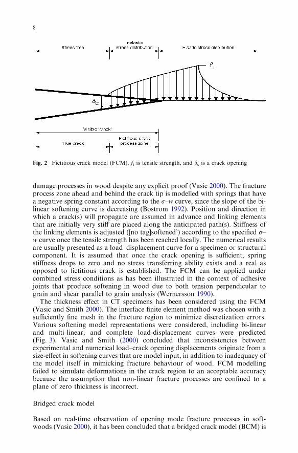
damage processes in wood despite any explicit proof (Vasic 2000). The fractureprocess zone ahead and behind the crack tip is modelled with springs that havea negative spring constant according to the r–w curve, since the slope of the bi-linear softening curve is decreasing (Bostrom 1992). Position and direction inwhich a crack(s) will propagate are assumed in advance and linking elementsthat are initially very stiff are placed along the anticipated path(s). Stiffness ofthe linking elements is adjusted ([no tag]softened’) according to the specified r–w curve once the tensile strength has been reached locally. The numerical resultsare usually presented as a load–displacement curve for a specimen or structuralcomponent. It is assumed that once the crack opening is sufficient, springstiffness drops to zero and no stress transferring ability exists and a real asopposed to fictitious crack is established. The FCM can be applied undercombined stress conditions as has been illustrated in the context of adhesivejoints that produce softening in wood due to both tension perpendicular tograin and shear parallel to grain analysis (Wernersson 1990).
The thickness effect in CT specimens has been considered using the FCM(Vasic and Smith 2000). The interface finite element method was chosen with asufficiently fine mesh in the fracture region to minimize discretization errors.Various softening model representations were considered, including bi-linearand multi-linear, and complete load-displacement curves were predicted(Fig. 3). Vasic and Smith (2000) concluded that inconsistencies betweenexperimental and numerical load–crack opening displacements originate from asize-effect in softening curves that are model input, in addition to inadequacy ofthe model itself in mimicking fracture behaviour of wood. FCM modellingfailed to simulate deformations in the crack region to an acceptable accuracybecause the assumption that non-linear fracture processes are confined to aplane of zero thickness is incorrect.
Bridged crack model
Based on real-time observation of opening mode fracture processes in soft-woods (Vasic 2000), it has been concluded that a bridged crack model (BCM) is
Fig. 2 Fictitious crack model (FCM), ft is tensile strength, and dc is a crack opening
8

a correct theoretical NLFM representation of wood (Vasic and Smith 2002) .Figure 4 gives a schematic of how the model is implemented. The conceptualdifference between FCM and BCMmodels concerns whether a stress singularityis permitted at the crack tip. The BCM assumes that a stress singularity at asharp crack tip co-exists with a bridging zone behind the crack tip, i.e., thebridging zone is not fictitious as in the FCM.
The main assumptions of the BCM is that fracture occurs when the criticalfracture toughness is reached at the tip of the crack. The criterion for crack
Fig. 4 Bridged crack model (BCM)
Fig. 3 Application of the FCM to predict load–crack opening displacements
9

extension and opening is therefore the same as for LEFM crack extension.Thus, the fracture criterion is stress based and fracture toughening during crackgrowth can be represented by simply adding the stress contributed frombridging fibres (or other toughening mechanisms) to the net crack tip stressintensity. The net toughness Knet=Ko + Kb where Ko is the intrinsic toughnessat the crack tip and Kb the bridging toughness.
Quantitative evaluation of the inelastic contribution Kb is crucial for properapplication of the BCM. Results from the quantitative SEM study by Vasic(2000) show that at least for the opening mode, the effect of bridging stresses isto decrease crack opening displacements and shield the crack tip. In a numericalstudy on tapered DCB fracture specimens by Vasic and Smith (2003), bridgingfibres were simulated with the application of parabolic pressure load along thecrack faces. The FEM code used had the capability of direct computation offracture related parameters for orthotropic materials and computation of en-ergy release rates GIc due to external loading and GIb due to bridging stresses.Net critical stress intensity factor KIc-net was obtained from the energy releaserate GIc-net using the harmonic orthotropic modulus of elasticity E*. The con-cept relates to [no tag]small-scale bridging’ where the effect of the stress sin-gularity is strong relative to the effect of bridging stresses. This presumes thesize-effect due to bridging to be negligible, as opposed to [no tag]large-scalebridging’ (Bao and Suo 1992). The FEM code also had the capability of implicit[no tag]shifting’ of nodes in the elements around the crack tip to create a stresssingularity. Three-noded CONT2 elements were inserted along the zones ex-pected to be in contact. Elastic orthotropic properties of spruce were assumedbased on the values given by Bodig and Jayne (1982). Output from the analysisincludes the wedge load P that splits the specimen. Figure 5 shows fracturetoughness versus crack length results. As can be deduced, the influence ofbridging stresses increases with any increase in the size of the bridging zone ifthe maximum bridging stress is kept constant. Net and elastic fractureparameters vary with increasing size of the bridging zone, and reach the max-imum value when the crack length equals the intrinsic flaw size for the material,which for spruce is 4 mm (Vasic 2000).
Lattice fracture model
This section discusses lattice models as an alternative to the more usual con-tinuum-based representations that are discussed above. Discrete elementswithin lattice arrangements simulate real ultrastructure features. Therefore, it isstraightforward to explicitly incorporate heterogeneity and variability makinglattice models a natural choice for representing disordered materials (Curtinand Scher 1990; Herrmann and Roux 1990). It follows that such models can beused to represent wood that embodies both structured and random heteroge-neity at various length scales. Being morphology-based the modelling eliminateserrors associated with homogenization which occurs in continuum-based FEA.In the past lattice models have been used mainly with concrete-based materialsand incorporated both random and uniform lattice geometry with uniform andvariable elements (Jirasek and Bazant 1995; Schlangen 1995; Schlangen andGarboczi 1996, 1997).
The material is represented as an array of nodes connected by a network ofdiscrete beam or spring elements. Figure 6 shows one possible discretization
10
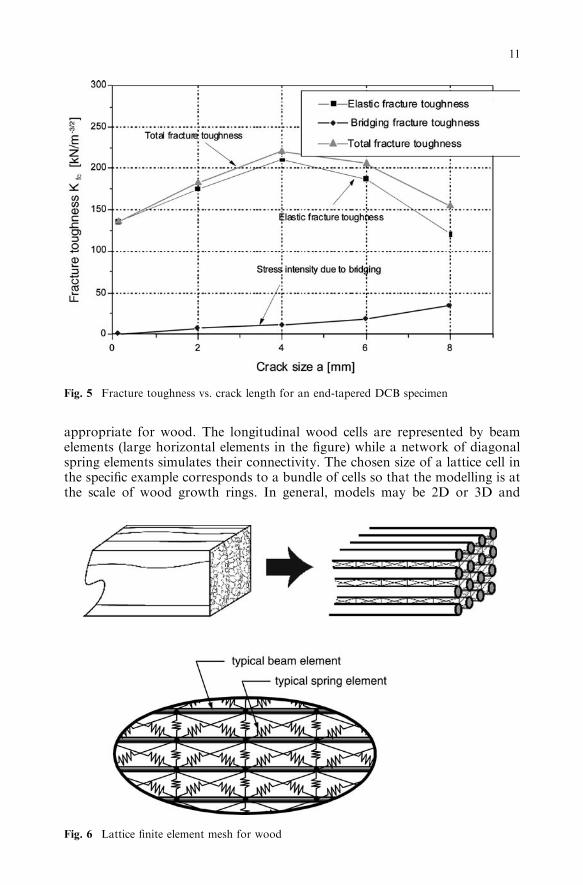
appropriate for wood. The longitudinal wood cells are represented by beamelements (large horizontal elements in the figure) while a network of diagonalspring elements simulates their connectivity. The chosen size of a lattice cell inthe specific example corresponds to a bundle of cells so that the modelling is atthe scale of wood growth rings. In general, models may be 2D or 3D and
Fig. 6 Lattice finite element mesh for wood
Fig. 5 Fracture toughness vs. crack length for an end-tapered DCB specimen
11

elements defined on any appropriate scale. In order to account for pre-existingheterogeneities, disorder of wood ultrastructure is introduced via statisticalvariation of element stiffness and strength characteristics. Stiffness and strengthcharacteristics can be assumed to fit a Gaussian (or another) distribution withspecified mean and standard deviation. This explicitly introduces the effects ofheterogeneity with coefficients of variation typically ranging from 20 to 40%and dependent upon the species (Landis et al. 2002). The model is solved usingtraditional FEA, calculating element forces and comparing them with previ-ously established strength. Once the strength of any element has been reached,it is considered broken and its contribution to the global stiffness matrix isremoved. The system is re-solved under particular displacement or load con-trolled boundary conditions until criteria for failure of the complete system(specimen) have been satisfied. Clearly, progressive failure is being captured,and damage development is easily followed. Monte Carlo analysis proceduresare used to produce a set of pseudo experimental data.
A lattice network for a prismatic tension perpendicular to grain specimenwith a rectangular cross-section was developed by the authors. Sensitivityanalysis revealed that results stabilize at a beam element length of 0.5 mm andbeam element spacing of 0.25 mm. A comparison between numerical andexperimental load–displacement curves produced under load control is given inFig. 7, while a typical simulated damaged lattice is shown in Fig. 8. The latticeshows the main crack being bridged by cells or cell bundles that are responsiblefor the long tail on the load–displacement curve. This and dispersion of damagethroughout a specimen are also characteristic of real specimens. Redundancy inlattice networks allows for the possibility of multiple load paths and hencestable progressive failure, but does not preclude the possibility of unstablefailure, which is consistent with experimental observations (Vasic 2000). Similarconclusions follow from simulation of the single-edge notched tension specimen(Landis et al. 2002).
Lattice element properties are not chosen arbitrarily. As elaborated by Da-vids et al. (2003), element properties are determined from matching the globallattice response to the orthotropic elastic properties of wood in bulk. The
Fig. 7 Lattice fracture model vs. experimental tension perpendicular to grain response underdisplacement control
12

parameters of the model that can be adjusted are element aspect ratio, the anglethat defines the orientation of the diagonal members, and the mean stiffness ofeach type of element. Optimal mean values of elastic constants are assumed tobe those that minimize the normalized least-squares objective function of theorthotropic bulk wood values. Other properties such as mean strengths andcoefficients of variation are determined from an adjustment procedure thatmatches experimental and nominal numerical bulk wood response in shearparallel to grain, radial tension perpendicular to grain and tension parallel tograin.
The research effort in developing this numerical framework of LFM is still inprogress and numerous issues are yet to be resolved before the approach canachieve its full potential. Like all other fracture models applied to wood theLFM does not yet recognize that wood embodies both structured andunstructured inhomogeneity.
Non-linear fracture models
There exist several commercial finite element programs specifically aimed atfracture analysis of structural components. A brief discussion of what isavailable is included here because the programs have capabilities potentiallyuseful in analysis of fracture in wood or wood-based composites. Thesenumerical tool boxes go beyond LEFM and prediction of crack initiation.
The FRANC fracture modelling code was developed by researchers atCornell University (Wawrzynek and Ingraffea 1985) and can analyse both 2Dand 3D problems with hydraulic fracture as the primary application target.FRANC3D provides a mechanism for simulation of arbitrary non-planarcracks along with re-meshing that follow crack growth using LEFM andNLFM. It relies on a hierarchy of topological models for multiple, non-planar,arbitrary shaped cracks which can be on surfaces, interfaces or the interior. Thegeometry of a specimen evolves over the range of an analysis. The commonprocedure for incremental numerical simulation of crack propagation is: (1)accurate extraction of stress intensity factors along an arbitrary three-dimen-sional front; (2) determination of the direction of extension and the crackgrowth increment; and (3) including the effect of neighbouring features such asinteraction with other cracks, boundaries and material interfaces.
The MERLIN fracture modelling code developed by the researchers at theUniversity of Colorado (Saouma et al. 1994) is primarily intended for appli-cation to reinforced concrete and dams. This code also has 2D and 3D capa-bilities, including LEFM and NLFM. The feature for simulation of crack
Fig. 8 Typical lattice damage pattern tension perpendicular to grain response underdisplacement control
13

propagation is available with the choice of discrete and smeared crack models.Constitutive models encompass orthotropic materials. Both static and dynamicanalyses are feasible. In 3D analysis stress intensity factors and energy releaserates are computed based on the domain integral method. A crack propagationfeature of special significance to fracture analysis in wood is the ability tohandle mixed-mode conditions.
General comments
It is clear from the above that few fracture models were developed withbehaviour of wood in mind, and that available models have quite differentcapabilities. LEFM and derivative modelling concepts are those most com-monly adopted. They require an initial crack(s) of predetermined size, locationand orientation to be specified and are capable of predicting what level ofloading will cause the crack to propagate. If one ignores structured and randominhomogeneity in the material and assumes wood is a continuum it is usuallyquite easy to select where an initial crack will be located because there will bestrong stress concentrations. In two dimensions, the orientation can be assumedalong the grain because of the strong elastic anisotropy, but in three dimensionsthe orientation can be difficult to predict. Suitable initial crack lengths, or crackfrom shapes in three dimensions, can be judged based on test observations andexperience. Experience shows that LEFM and derived models successfullypredict the failure load when general dimensions of a component are largecompared to the fracture process zone. Although the ratio of the fractureprocess zone to the initial crack length can also be an issue, LEFM and derivedconcepts are usually sufficient for predictions associated with global behaviourof [no tag]structural sized members’ and complete structural systems (Smithet al. 2003).
Fictitious crack, bridging crack and lattice modelling concepts predict crackevolution as well as propagation loads for components. In the cases of FCMand BCM it is still necessary to predict the location and orientation of anycracks, but not to assign them an initial length. Such models can encompass thetransition from an artificial (cut or otherwise machined) crack to a naturalcrack that mobilizes toughening mechanisms like fibre bridging. Lattice fracturemodels are the only ones to date capable of predicting unconstrained crackinitiation, propagation and evolution. As matters stand, the drawbacks withLFM are that there is no established process for assigning element stiffness andstrength properties that is independent of calibration processes, and computa-tional demands can be large. It is anticipated however that both these limita-tions will be mitigated within the near future. In the longer term LFM should bedeveloped to the stage where it can handle issues such as slow crack growth,load cycling and effects of moisture movements in wood. Experience shows thatadoption of more complex models like FCM and BCM is necessary when thestress field developed around a crack tip interacts with high stresses producedby features other than cracks, e.g. gluelines and mechanical fasteners (Smithet al. 2003). As already implied, LFM is only likely to be applied under specialcircumstances.
Fracture experiments and modelling for wood have focussed on the effects ofso-called static loads (monotonic loading that causes failure in about 0.1 h or
14

less), even though such load conditions are rarely, if ever, encountered inpractice. Thus, future work needs to focus on extending knowledge and con-cepts to other loading regimes and time scales. Consideration of longer timescales also means that factors such as the effects of moisture and perhapstemperature should not be ignored.
Conclusion
Analysts have available to them a broad range of fracture modelling conceptsthat can be applied to wood components and implemented via FEA. Whether itis essential that a chosen model mimics the real failure processes in wooddepends on the problem to be analysed and the nature of predictions that arerequired. The most important factors are that the capabilities of each modellingconcept are known and that an appropriate choice is made for the problem athand. This paper is aimed at achieving these ends.
References
Aicher SM, Schmidt S, Brunold S (1995) Design of timber beams with holes by means offracture mechanics. Proceedings of the international council for research and innovation inconstruction—working commission W18 (CIB-W18), meeting 28, Copenhagen, Denmark
Aliabadi MH, Rooke DP (1993) Advances in boundary element methods for fracturemechanics. Series: computational mechanics. Wessex Institute of Technology, South-ampton, UK
An D (1987) Weight function theory for rectilinear anisotropic body. Int J Fract 34:85–109Atluri SN, Kobayashi AS, Nakagaki M (1975) A finite element program for fracture analysis
of composite material. In: Fracture mechanics of composites. ASTM STP 593, Philadel-phia, PA
Bao G, Suo Z (1992) Remarks on crack-bridging concepts. Appl Mech Rev ASME 45(8):355–366
Barsoum RS (1975) Application of quadratic isoparametric finite elements in linear fracturemechanics. Int J Fract 10:603–605
Barsoum RS (1976) On the use of isoparametric finite elements in linear fracture mechanics. IntJ Numer Methods Eng 10:25–37
Bathe KJ (1996) Finite element procedures. Prentice Hall, New Jersey, USABazant ZP, Planas J (1998) Fracture and size effect in concrete and other quasibrittle materials.
CRC Press, Boca RatonBodig J, Jayne BA (1982) Mechanics of wood and wood composites. Van Nostrand Reinhold,
New York
Boone TJ, Wawrzynek PA, Ingraffea AR (1987) Finite element modelling of fracture propa-gation in orthotropic materials. Eng Fract Mech 26(2):185–201
Bostrom L (1992) Method for determination of the softening behaviour of wood and appli-cability of a non-linear fracture mechanics model. Lund University, TVBM-1012, Lund,Sweden
Bowie OL, Freese CE (1972) Central crack in plane orthotropic rectangular sheet. Int J FractMech 8(1):49–58
Brabia CA (1978) The boundary element for engineers. Pentech Press, LondonCook RD (1995) Concepts and applications of finite element analysis. Wiley & Sons, New
York, pp 336
15

Curtin W, Scher H (1990) Brittle fracture of disordered materials: a spring network model.J Mater Res 5(3):535–553
Davids WG, Landis EN, Vasic S (2003) Lattice models for the prediction of load-inducedfailure and damage in wood. Wood Fiber Sci 35(1):120–135
Foschi RO, Barrett JD (1976) Stress intensity factors in anisotropic plates using singularisoparametric elements. Int J Numer Mech Eng 10(6):1281–1287
Henshell RD, Shaw KG (1975) Crack tip finite elements are unnecessary. Int J NumerMethods Eng 9(3):495–507
Herrmann HJ, Roux S (1990) Statistical models for the fracture of disordered media. NorthHolland, Amsterdam
Hillerborg A, Modeer M, Petterson PE (1976) Analysis of crack formation and crack growthin concrete by means of fracture mechanics and finite elements. Cem Concr Res 6:773–782
Irwin GR (1957) Analysis of stresses and strains near the end of a crack traversing a plate.J Appl Mech 24:361–364
Irwin GR (1958) Fracture. In Handbuch der Physik, vol VI. Springer, Berlin Heidelberg NewYork
Jirasek M, Bazant Z (1995) Macroscopic fracture characteristics of random particle systems.Int J Fract 69:201–228
Kanninen MF, Rybicki EF, Brinson HF (1977) A critical look at current applications offracture mechanics to the failure of fibre-reinforced composites. Composites 8:17–22
Landis EN, Vasic S, Davids WG, Parrod P (2002) Coupled experiments and simulations ofmicrostructural damage in wood. Exper Mech 42(4):389–394
Li YN, Liang RY (1994) Peak load determination in linear fictitious crack model. J Eng MechASME 120(2):232–249
Lum C, Foschi RO (1988) Arbitrary V-notches in orthotropic plates. ASCE J Eng Mech114(4):638–655
Rice RJ (1968) A path independent integral and the approximate analysis of strain concen-tration by notches and cracks. J Appl Mech 6:379–386
Rots JG, de Borst R (1988) Analysis of mixed-mode fracture of concrete. ASCE J Eng Mech113(11):1739–1758
Saouma V, Cervenka J, Reich R (1994) MERLIN finite element program. University ofColorado, http://www.ceae.colorado.edu/�saouma/merlin. Cited 11 November 2004
Saouma VE, Schwemmer D (1984) Numerical evaluation of the quarter-point crack tip ele-ment. Int J Numer Methods Eng 20:1629–1641
Schlangen E (1995) Experimental and numerical analysis of fracture processes in concrete.Research report, Technical University of Delft, Delft, The Netherlands
Schlangen E, Garboczi E (1996) New method for simulating fracture using an elasticallyuniform random geometry lattice. Int J Eng Sci 34(10):1131–1144
Schlangen E, Garboczi E (1997) Fracture simulations of concrete using lattice models: com-putational aspects. Eng Fract Mech 57(2/3):319–332
Sha GT, Yang CT (1985) Weight function calculations for mixed-mode fracture problems withthe virtual crack extension technique. Eng Fract Mech 21(6):1119–1149
16
Sha GT, Chen JK, Yang CT (1988) Energy perturbation finite element technique for damagetolerant design applications. Eng Fract Mech 29(2):197–218
Sih GC, Paris PC, Irwin GR (1965) On cracks in rectilinear anisotropic bodies. Int J Fract1:189–203
Smith I, Vasic S (2003) Fracture behaviour of softwood. Mech Mater 35:803–815Smith I, Tan DM, Chui YH (1996) Critical reaction forces for notched timber members.
Proceedings of the international wood engineering conference, New Orleans, LouisianaState University, Baton Rouge, USA, pp 3460–3471
Smith I, Landis E, Gong M (2003) Fracture and fatigue in wood. Wiley, Chichester, UK
Stanzl-Tschegg SE, Tan DM, Tschegg EK (1995) New splitting method for wood fracturecharacterization. Wood Sci Technol 29:31–50
Valentin G, Adjanohoun G (1992) Applicability of classical isotropic fracture mechanicsspecimens to wood crack propagation studies. Mater Struct 25:3–13
Vasic S (2000) Applications of fracture mechanics to wood. PhD Thesis, University of NewBrunswick, Fredericton, NB, Canada
Vasic S, Smith I (2000) Non-linear fracture mechanics analysis of thickness effect in greenwood. Proceedings of the world conference of timber engineering 2000, Whistler, Canada,July 31–August 3
Vasic S, Smith I (2002) Bridging crack model for fracture of spruce. Eng Fract Mech 69:745–760
Vasic S, Smith I (2003) Contact-crack problem with friction in spruce. Holz Roh Werkst61:182–186
Vasic S, Smith I, Landis EN (2002) Fracture zone characterization—micro- mechanical study.Wood Fiber Sci 34(1):42–56
Wawrzynek PA, Ingraffea AR (1985) FRANC software. Cornell University, http://www.cfg.cornell.edu. Cited 11 November 2004
Wernersson H (1990) Fracture characterization of wood adhesive joints. Report TVSM-1006,Lund University, Division of Structural Mechanics, Lund, Sweden
Yamaguchi E, Chen WF (1990) Cracking model for finite element analysis of concretematerials. ASCE J Eng Mech 116(6):1242–1260
Zienkiewicz OC, Taylor RL (1988) The finite element method: vol 1 - basic formulation andlinear problems. McGraw Hill, London
Zienkiewicz OC, Taylor RL (1989) The finite element method: vol 2, solid and fluid mechanics,dynamics and non-linearity. McGraw Hill, London
17