Embed Size (px)
Citation preview
REPORTDEPARTMENT/UNIT: Vision / 3D VisionREPORT N°: IV070016
REPORT
DEPARTMENT/UNIT: Vision / 3D Vision REPORT N°: IV070016
TITLE
FINITE ELEMENT STRUCTURAL ANALYSIS OF THE TPD-2f SCREW FOR DENTAL IMPLANTS
PETITIONERCompany: TALLADIUM ESPAÑA Address: PLAÇA D´UTXESA 7, 5È ACity: LLEIDAP.O.: 25002Province: LLEIDATel.: 902101347Fax:
START DATE: 28/05/07END DATE: 8/06/07
Nº of Annexes: 0ASOCIACIÓN INDUSTRIAL DE ÓPTICA COLOR E IMAGEN I Calle Nicolás Copérnico, 7, 9, 11 y 13 I Apartado 139 I 46980
Paterna I Valencia I Tels. 96 131 80 51 . 96 131 80 66 I Fax 96 131 80 07 I e-mail:[email protected] I http://www.aido.es
1. INTRODUCTION
2. BACKGROUND
3. OBJECTIVES
4. STRUCTURAL ANALYSIS WITH THE FINITE ELEMENT METHOD
4.1. Mechanical properties of the material
4.2. Application of loads and movement restrictions
4.2.1.Torque setting
4.2.2.Turning restrictions
4.2.3.Displacement restrictions
4.3. Finite element model
4.4. Structural analysis
4.5. Results
5. CONCLUSIONS
REPORTDEPARTMENT/UNIT: Vision / 3D VisionREPORT N°: IV070016
1. INTRODUCTION
This report concerns the last stage of the studies performed on the TPD-2f screw for the project TILITE TALLADIUM ESPAÑA for the company Talladium España and carried out for the AIDO Asociación Industrial de Óptica, Color e Imagen. This last stage considers the final structural analysis with the aim of verifying the modifications carried out on the design of the TPD-2f screw in the previous stage
2. BACKGROUND
In the previous stages analysis with the finite element method was carried out to evaluate the mechanical resistance of dental implant pieces belonging to the company Talladium España. The TPD-2f screw was redesigned according to the results obtained.
3. OBJECTIVE
The objective of this stage is to verify that the modifications carried out on the original design of the TPD-2f screw, increase its mechanical resistance when the piece is subjected to the forces envisaged in its design.
4. STRUCTURAL ANALYSIS WITH THE FINITE ELEMENT METHOD
Laid out below are details on the parameters, simplifications and results of structural analysis on the TPD-2f screw for dental implants from the company Talladium España, using the finite element method by means of the Pro/Mechanica module of the Pro/Engineer Wildfire 3.0. software.
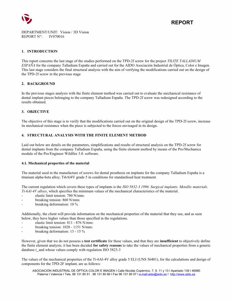
4.1. Mechanical properties of the material
The material used in the manufacture of screws for dental prosthesis on implants for the company Talladium España is a titanium alpha-beta alloy; Ti6Al4V grade 5 in conditions for standardised heat treatment.
The current regulation which covers these types of implants is the ISO 5832-3 1996. Surgical implants. Metallic materials. Ti-6Al-4V alloys, which specifies the minimum values of the mechanical characteristics of the material.- elastic limit tension: 780 N/mm2
- breaking tension: 860 N/mm2
- breaking deformation: 10 %
Additionally, the client will provide information on the mechanical properties of the material that they use, and as seen below, they have higher values than those specified in the regulations.- elastic limit tension: 811 - 876 N/mm2
- breaking tension: 1028 - 1151 N/mm2
- breaking deformation: 13 - 15 %
However, given that we do not possess a test certificate for these values, and that they are insufficient to objectively define the finite element analysis; it has been decided for safety reasons to take the values of mechanical properties from a generic database ( and whose values comply with regulation ISO 5823-3
The values of the mechanical properties of the Ti-6Al-4V alloy grade 5 ELI (UNS 56401), for the calculations and design of components for the TPD-2F implant, are as follows:
ASOCIACIÓN INDUSTRIAL DE ÓPTICA COLOR E IMAGEN I Calle Nicolás Copérnico, 7, 9, 11 y 13 I Apartado 139 I 46980Paterna I Valencia I Tels. 96 131 80 51 . 96 131 80 66 I Fax 96 131 80 07 I e-mail:[email protected] I http://www.aido.es
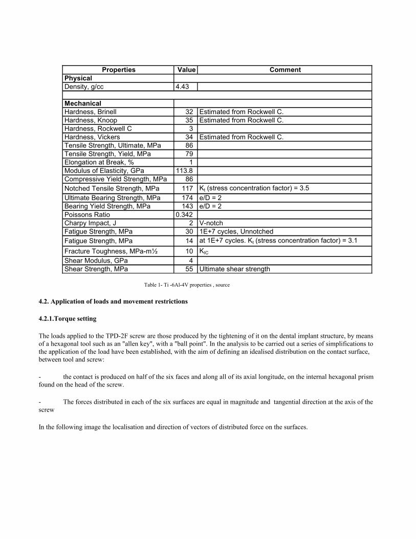
Properties Value CommentPhysicalDensity, g/cc 4.43
MechanicalHardness, Brinell 32
6Estimated from Rockwell C.
Hardness, Knoop 354
Estimated from Rockwell C.Hardness, Rockwell C 3
5Hardness, Vickers 341
Estimated from Rockwell C.Tensile Strength, Ultimate, MPa 86
0Tensile Strength, Yield, MPa 790Elongation at Break, % 15Modulus of Elasticity, GPa 113.8
Compressive Yield Strength, MPa 860Notched Tensile Strength, MPa 117
0Kt (stress concentration factor) = 3.5
Ultimate Bearing Strength, MPa 1740
e/D = 2Bearing Yield Strength, MPa 143
0e/D = 2
Poissons Ratio 0.342Charpy Impact, J 2
4V-notch
Fatigue Strength, MPa 300
1E+7 cycles, UnnotchedFatigue Strength, MPa 14
0at 1E+7 cycles. Kt (stress concentration factor) = 3.1
Fracture Toughness, MPa-m½ 100
KIC
Shear Modulus, GPa 44Shear Strength, MPa 55
0Ultimate shear strength
Table 1- Ti -6Al-4V properties , source
4.2. Application of loads and movement restrictions
4.2.1.Torque setting
The loads applied to the TPD-2F screw are those produced by the tightening of it on the dental implant structure, by means of a hexagonal tool such as an "allen key", with a "ball point". In the analysis to be carried out a series of simplifications to the application of the load have been established, with the aim of defining an idealised distribution on the contact surface, between tool and screw:
- the contact is produced on half of the six faces and along all of its axial longitude, on the internal hexagonal prism found on the head of the screw.
- The forces distributed in each of the six surfaces are equal in magnitude and tangential direction at the axis of the screw
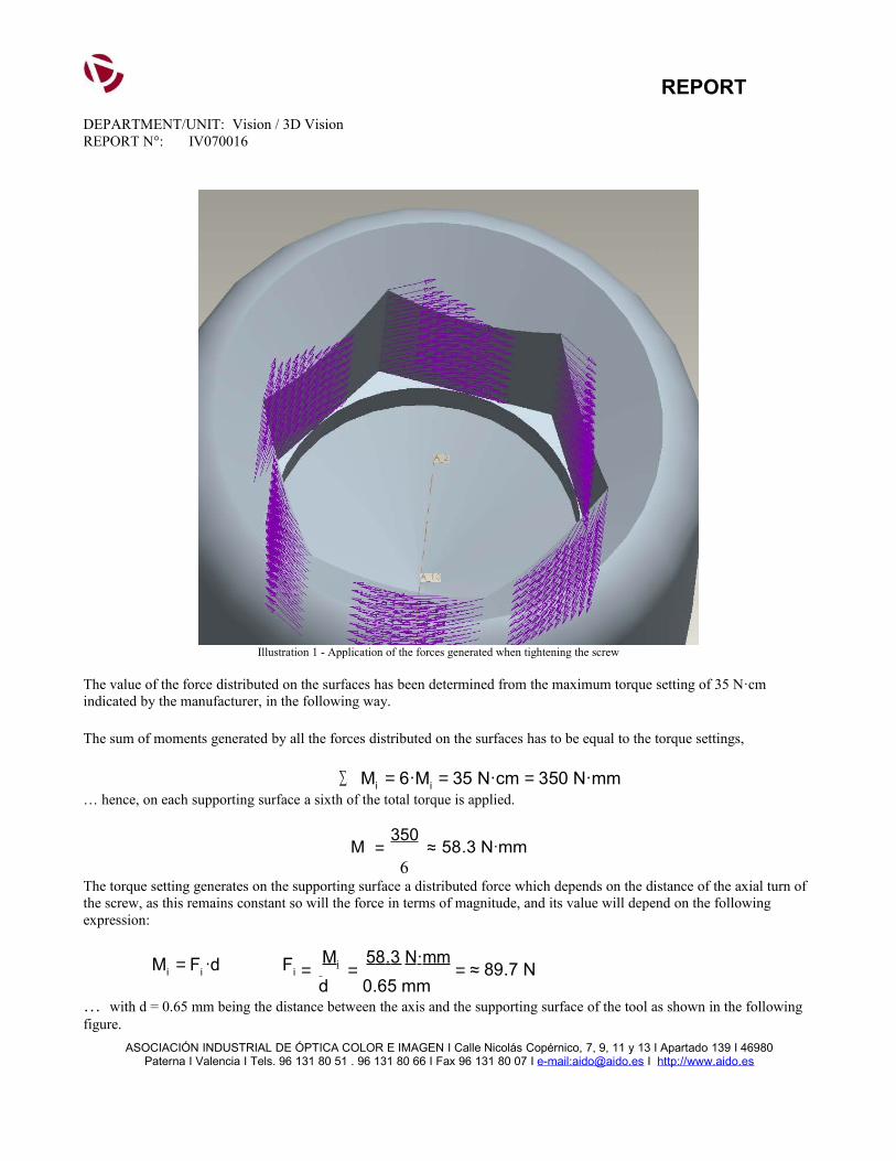
In the following image the localisation and direction of vectors of distributed force on the surfaces.
REPORTDEPARTMENT/UNIT: Vision / 3D VisionREPORT N°: IV070016
Illustration 1 - Application of the forces generated when tightening the screw
The value of the force distributed on the surfaces has been determined from the maximum torque setting of 35 N·cm indicated by the manufacturer, in the following way.
The sum of moments generated by all the forces distributed on the surfaces has to be equal to the torque settings,
∑ Mi = 6·Mi = 35 N·cm = 350 N·mm… hence, on each supporting surface a sixth of the total torque is applied.
M = 350
≈ 58.3 N·mm 6The torque setting generates on the supporting surface a distributed force which depends on the distance of the axial turn of the screw, as this remains constant so will the force in terms of magnitude, and its value will depend on the following expression:
Mi = Fi ·d Fi = Mi = 58 . 3 N·mm
= ≈ 89.7 N d 0.65 mm
… with d = 0.65 mm being the distance between the axis and the supporting surface of the tool as shown in the following figure.
ASOCIACIÓN INDUSTRIAL DE ÓPTICA COLOR E IMAGEN I Calle Nicolás Copérnico, 7, 9, 11 y 13 I Apartado 139 I 46980Paterna I Valencia I Tels. 96 131 80 51 . 96 131 80 66 I Fax 96 131 80 07 I e-mail:[email protected] I http://www.aido.es
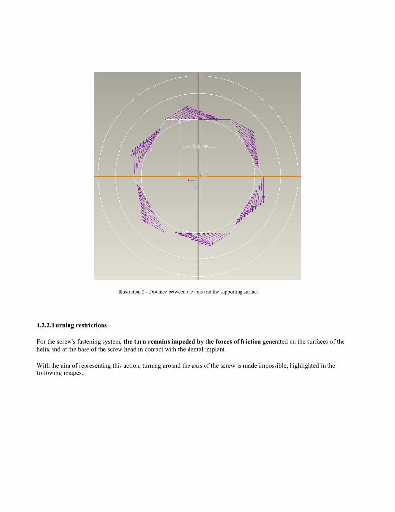
Illustration 2 - Distance between the axis and the supporting surface
4.2.2.Turning restrictions
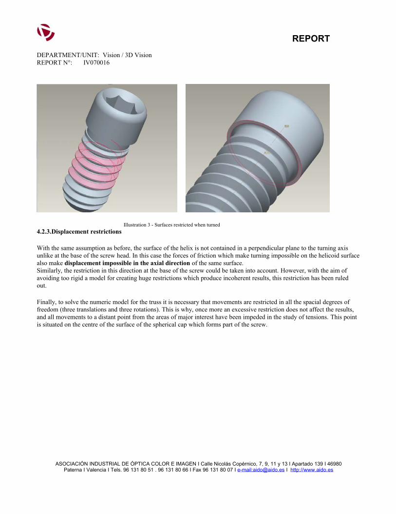
For the screw's fastening system, the turn remains impeded by the forces of friction generated on the surfaces of the helix and at the base of the screw head in contact with the dental implant.
With the aim of representing this action, turning around the axis of the screw is made impossible, highlighted in the following images.
REPORTDEPARTMENT/UNIT: Vision / 3D VisionREPORT N°: IV070016
Illustration 3 - Surfaces restricted when turned4.2.3.Displacement restrictions
With the same assumption as before, the surface of the helix is not contained in a perpendicular plane to the turning axis unlike at the base of the screw head. In this case the forces of friction which make turning impossible on the helicoid surface also make displacement impossible in the axial direction of the same surface.Similarly, the restriction in this direction at the base of the screw could be taken into account. However, with the aim of avoiding too rigid a model for creating huge restrictions which produce incoherent results, this restriction has been ruled out.
Finally, to solve the numeric model for the truss it is necessary that movements are restricted in all the spacial degrees of freedom (three translations and three rotations). This is why, once more an excessive restriction does not affect the results, and all movements to a distant point from the areas of major interest have been impeded in the study of tensions. This point is situated on the centre of the surface of the spherical cap which forms part of the screw.
ASOCIACIÓN INDUSTRIAL DE ÓPTICA COLOR E IMAGEN I Calle Nicolás Copérnico, 7, 9, 11 y 13 I Apartado 139 I 46980Paterna I Valencia I Tels. 96 131 80 51 . 96 131 80 66 I Fax 96 131 80 07 I e-mail:[email protected] I http://www.aido.es
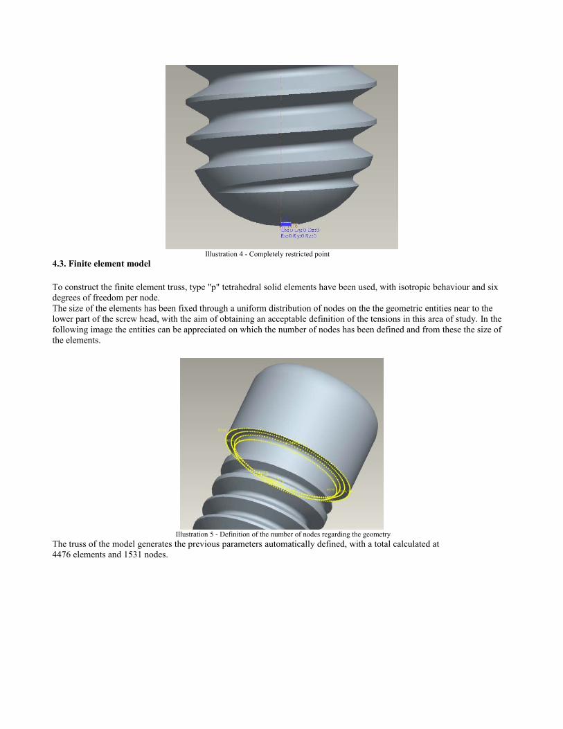
Illustration 4 - Completely restricted point4.3. Finite element model
To construct the finite element truss, type "p" tetrahedral solid elements have been used, with isotropic behaviour and six degrees of freedom per node.The size of the elements has been fixed through a uniform distribution of nodes on the the geometric entities near to the lower part of the screw head, with the aim of obtaining an acceptable definition of the tensions in this area of study. In the following image the entities can be appreciated on which the number of nodes has been defined and from these the size of the elements.
Illustration 5 - Definition of the number of nodes regarding the geometryThe truss of the model generates the previous parameters automatically defined, with a total calculated at4476 elements and 1531 nodes.
REPORTDEPARTMENT/UNIT: Vision / 3D VisionREPORT N°: IV070016
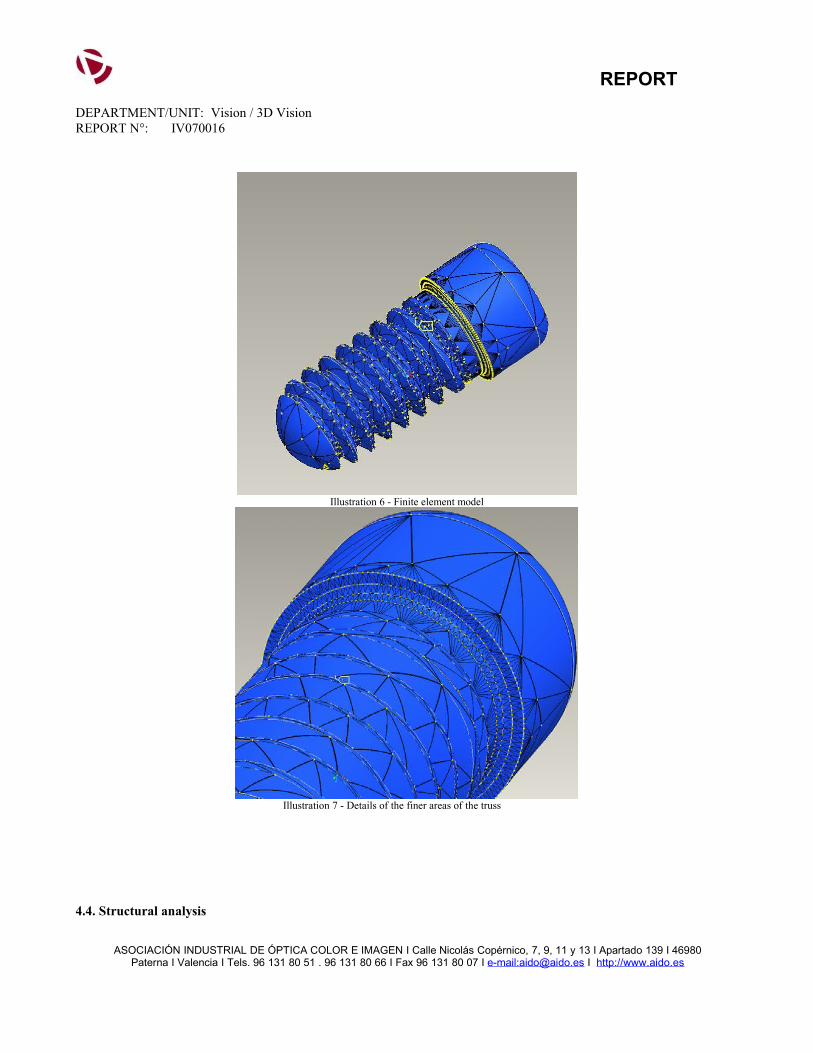
Illustration 6 - Finite element model
Illustration 7 - Details of the finer areas of the truss
4.4. Structural analysis
ASOCIACIÓN INDUSTRIAL DE ÓPTICA COLOR E IMAGEN I Calle Nicolás Copérnico, 7, 9, 11 y 13 I Apartado 139 I 46980Paterna I Valencia I Tels. 96 131 80 51 . 96 131 80 66 I Fax 96 131 80 07 I e-mail:[email protected] I http://www.aido.es
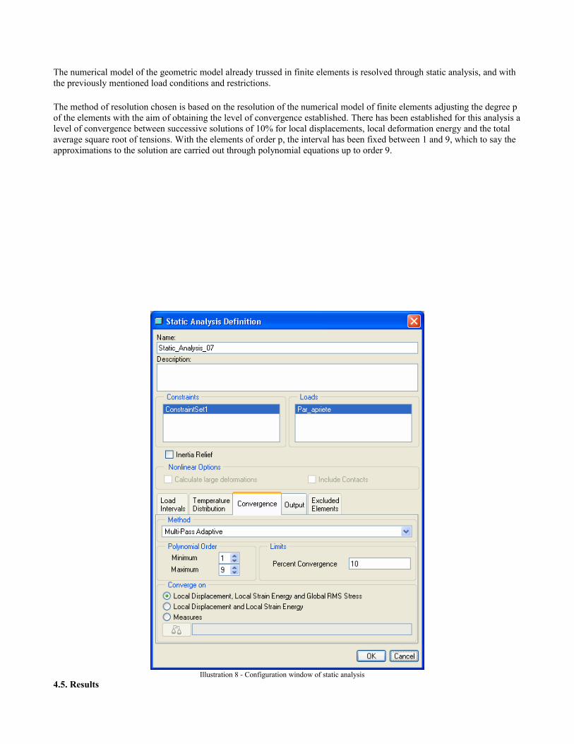
The numerical model of the geometric model already trussed in finite elements is resolved through static analysis, and with the previously mentioned load conditions and restrictions.
The method of resolution chosen is based on the resolution of the numerical model of finite elements adjusting the degree p of the elements with the aim of obtaining the level of convergence established. There has been established for this analysis a level of convergence between successive solutions of 10% for local displacements, local deformation energy and the total average square root of tensions. With the elements of order p, the interval has been fixed between 1 and 9, which to say the approximations to the solution are carried out through polynomial equations up to order 9.
Illustration 8 - Configuration window of static analysis4.5. Results
REPORTDEPARTMENT/UNIT: Vision / 3D VisionREPORT N°: IV070016
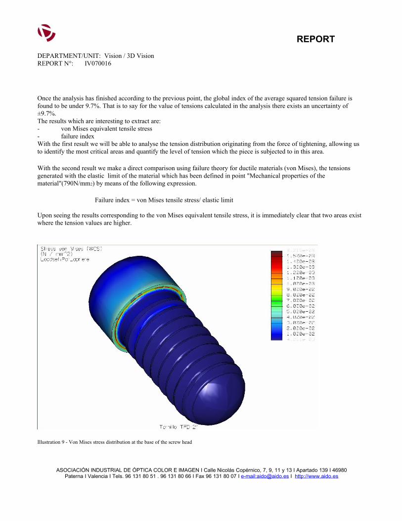
Once the analysis has finished according to the previous point, the global index of the average squared tension failure is found to be under 9.7%. That is to say for the value of tensions calculated in the analysis there exists an uncertainty of ±9.7%.The results which are interesting to extract are:- von Mises equivalent tensile stress- failure indexWith the first result we will be able to analyse the tension distribution originating from the force of tightening, allowing us to identify the most critical areas and quantify the level of tension which the piece is subjected to in this area.
With the second result we make a direct comparison using failure theory for ductile materials (von Mises), the tensions generated with the elastic limit of the material which has been defined in point "Mechanical properties of the material"(790N/mm2) by means of the following expression.
Failure index = von Mises tensile stress/ elastic limit
Upon seeing the results corresponding to the von Mises equivalent tensile stress, it is immediately clear that two areas exist where the tension values are higher.
Illustration 9 - Von Mises stress distribution at the base of the screw head
ASOCIACIÓN INDUSTRIAL DE ÓPTICA COLOR E IMAGEN I Calle Nicolás Copérnico, 7, 9, 11 y 13 I Apartado 139 I 46980Paterna I Valencia I Tels. 96 131 80 51 . 96 131 80 66 I Fax 96 131 80 07 I e-mail:[email protected] I http://www.aido.es
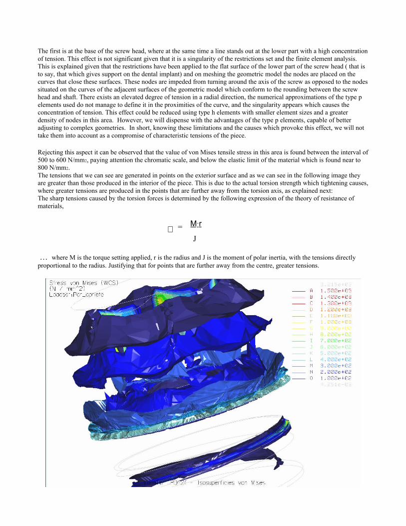
The first is at the base of the screw head, where at the same time a line stands out at the lower part with a high concentration of tension. This effect is not significant given that it is a singularity of the restrictions set and the finite element analysis. This is explained given that the restrictions have been applied to the flat surface of the lower part of the screw head ( that is to say, that which gives support on the dental implant) and on meshing the geometric model the nodes are placed on the curves that close these surfaces. These nodes are impeded from turning around the axis of the screw as opposed to the nodes situated on the curves of the adjacent surfaces of the geometric model which conform to the rounding between the screw head and shaft. There exists an elevated degree of tension in a radial direction, the numerical approximations of the type p elements used do not manage to define it in the proximities of the curve, and the singularity appears which causes the concentration of tension. This effect could be reduced using type h elements with smaller element sizes and a greater density of nodes in this area. However, we will dispense with the advantages of the type p elements, capable of better adjusting to complex geometries. In short, knowing these limitations and the causes which provoke this effect, we will not take them into account as a compromise of characteristic tensions of the piece.
Rejecting this aspect it can be observed that the value of von Mises tensile stress in this area is found between the interval of 500 to 600 N/mm2, paying attention the chromatic scale, and below the elastic limit of the material which is found near to 800 N/mm2.The tensions that we can see are generated in points on the exterior surface and as we can see in the following image they are greater than those produced in the interior of the piece. This is due to the actual torsion strength which tightening causes, where greater tensions are produced in the points that are further away from the torsion axis, as explained next: The sharp tensions caused by the torsion forces is determined by the following expression of the theory of resistance of materials,
= M·r
J
… where M is the torque setting applied, r is the radius and J is the moment of polar inertia, with the tensions directly proportional to the radius. Justifying that for points that are further away from the centre, greater tensions.
REPORTDEPARTMENT/UNIT: Vision / 3D VisionREPORT N°: IV070016
Illustration 10 - Isosurfaces of von Mises tensile stress
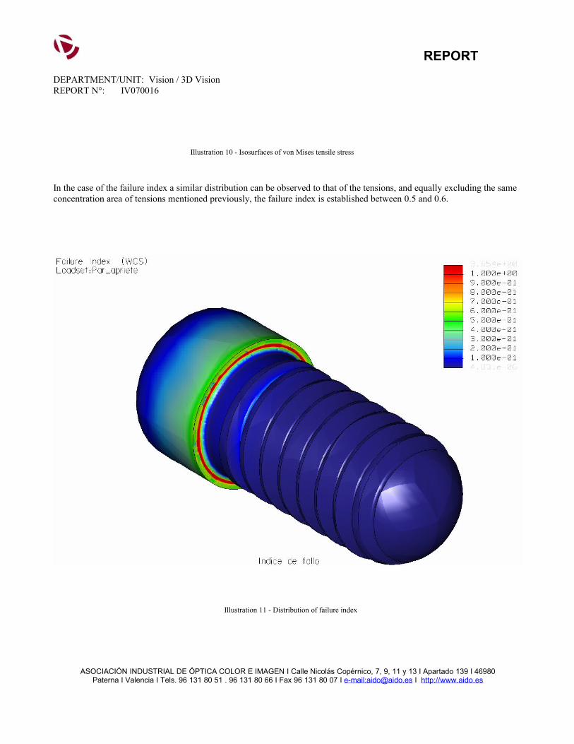
In the case of the failure index a similar distribution can be observed to that of the tensions, and equally excluding the same concentration area of tensions mentioned previously, the failure index is established between 0.5 and 0.6.
Illustration 11 - Distribution of failure index
ASOCIACIÓN INDUSTRIAL DE ÓPTICA COLOR E IMAGEN I Calle Nicolás Copérnico, 7, 9, 11 y 13 I Apartado 139 I 46980Paterna I Valencia I Tels. 96 131 80 51 . 96 131 80 66 I Fax 96 131 80 07 I e-mail:[email protected] I http://www.aido.es
A more detailed study of von Mises tensile stresses and the failure index, about a representative area of the model provide a characteristic value which allows us to extract the conclusions a posteriori. It has been taken as a representative area to take the lower edge values of the screw head and are represented in the following graphs
In the graph a line is shown in blue following the values of the tensions and in orange the value of the failure index in the nodes situated on the edge. The intermittent lines are the average of these magnitudes for von Mises tensile stresses of 500 N/mm2 and for the failure index of 0.63.
Illustration 12 - Graph of von Mises stress value on a node and failure index.
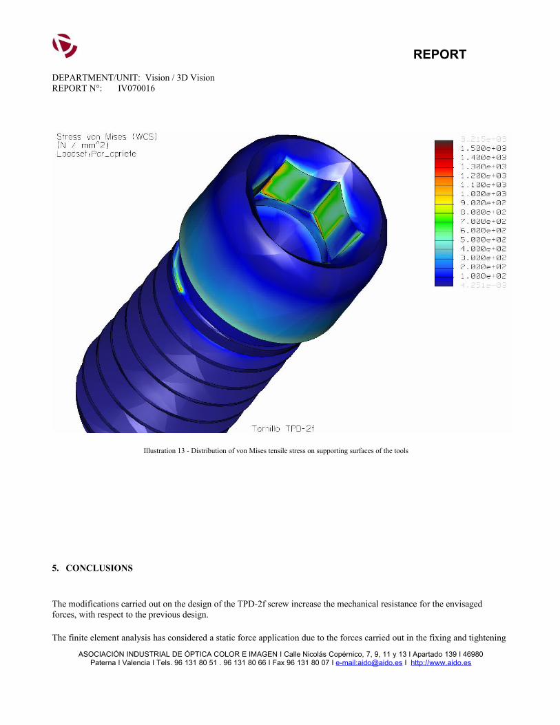
Another area where high tension values can be observed are the areas where forces have been applied which simulate contact with the tool. Paying attention to the simplifications carried out in the application of loads shown in previous sections, these results are not deciding factors when evaluating the mechanical resistance of this area for the following reasons:
- the application of loads and the supporting surfaces are an idealised approximation
- the superficial durability of the material is not taken into account in the analysis, neither is its plastic behaviour
REPORTDEPARTMENT/UNIT: Vision / 3D VisionREPORT N°: IV070016
Illustration 13 - Distribution of von Mises tensile stress on supporting surfaces of the tools
5. CONCLUSIONS
The modifications carried out on the design of the TPD-2f screw increase the mechanical resistance for the envisaged forces, with respect to the previous design.
The finite element analysis has considered a static force application due to the forces carried out in the fixing and tightening
ASOCIACIÓN INDUSTRIAL DE ÓPTICA COLOR E IMAGEN I Calle Nicolás Copérnico, 7, 9, 11 y 13 I Apartado 139 I 46980Paterna I Valencia I Tels. 96 131 80 51 . 96 131 80 66 I Fax 96 131 80 07 I e-mail:[email protected] I http://www.aido.es
of the dental implants by the company Talladium España. The results obtained show that the tensions coming from said actions (500 N/mm2) are found to be below the elastic limit of the material (790 N/mm2), from which the deformations caused make the piece unusable.
The failure index (0.63) obtained from von Mises failure theory or Distortion Energy theory is enough for the actions envisaged. However, if variable loads appear over time during the service life of the piece, it would be necessary to focus an exhaustive analysis to test its mechanical resistance under these conditions.
On the other hand, the analysis carried out is not determining to evaluate the mechanical resistance of the screw head, given that in this area contact is produced between the tool and the screw. The simplifications carried out with this contact are only idealised approximations, and it would be necessary to carry out a specific analysis on this area so that it were conclusive and took into account the distinct variables such as: contact surfaces, durability of the tool and screw materials.
However, with the tensions reached on these surfaces (between 700 y 800 N/mm2) we can deduce that the failure of this part of the piece will not be assumed. The superficial resistance of contact forces of the materials is related to the durability that the surface acquires, for example for steel of similar durability as the Ti-6Al-4V alloy in a normalised state, approximately 320 HB, it has superficial resistance equivalent to 1000 N/mm2. This resistance is greater than the tensions that have been obtained in the finite element analysis and under this criterion it can be deduced that damage would not be produced in the piece.
DEPARTMENT: Vision / 3D Vision
REPORT N°: IV070016
REPORTDEPARTMENT/UNIT: Vision / 3D VisionREPORT N°: IV070016
* AIDO guarantees the confidentiality of the data reflected in this report* This report will not be valid if corrections or amendments are made.
• The total or partial reproduction of this report in any way or by any means is prohibited without the expressed consent of AIDO and the petitioner.
Responsible for the report: Report supervisor:
Date, signature and position. Date, signature and position.
ASOCIACIÓN INDUSTRIAL DE ÓPTICA COLOR E IMAGEN I Calle Nicolás Copérnico, 7, 9, 11 y 13 I Apartado 139 I 46980Paterna I Valencia I Tels. 96 131 80 51 . 96 131 80 66 I Fax 96 131 80 07 I e-mail:[email protected] I http://www.aido.es