Embed Size (px)
Citation preview
INT. J. NUM. METH. HEAT FLUID FLOW, VOL. 4, 61-83 (1994)
FINITE ELEMENT SIMULATION OF LASER SURFACE TREATMENTS INCLUDING CONVECTION IN THE
MELT POOL
M. PICASSO† AND A. F. A. HOADLEY‡ † Département de Mathématiques and ‡ Laboratoire de Métallurgie Physique, MX-G
Ecole Polytechnique Fédérate de Lausanne, 1015 Lausanne, Switzerland
ABSTRACT A two-dimensional, macroscopic, stationary, finite element model is presented for both laser remelting and laser cladding of material surfaces. It considers, in addition to the heat transfer, the important fluid motion in the melt pool and the deformation of the liquid-gas interface. The velocity field in the melt is driven by thermocapillary forces for laser remelting, but also by forces due to powder injection for laser cladding. For a given velocity field within the liquid region, the stationary enthalpy (or Stefan) equation is solved. An efficient scheme allows the LU decomposition of the finite element matrix to be performed only once at the first iteration. Then, the velocity is updated using the Q1 — P0 element with penalty methods for treating both the incompressibility condition and the slip boundary conditions. Numerical results for three different processing speeds for both laser remelting and laser cladding demonstrate the efficiency and robustness of the numerical approach. The influence of the thermocapillary and powder injection forces on the fluid motion and subsequently on the melt pool shape is seen to be important. This kind of calculations is thus necessary in order to predict with precision the temperature gradients across the solidification interface, which are essential data for microstructure calculations.
KEY WORDS Laser surface treatments Finite elements Solidification Stefan problem Hydrodynamics Thermocapillary convection
INTRODUCTION
Laser surface treatments are high precision processes for enhancing the properties of a contact surface, without altering the mechanical properties of the bulk material. A fixed laser beam produces a melt pool on a moving substrate (laser remelting, see Figure 1). At the same time the injection of powder, by means of a carrier gas, into the melt region allows rapid mixing and melting in the liquid part (laser cladding, see Figure 2).
The aim of laser remelting is to induce changes in the microstructure of the surface, whereas the aim of laser cladding is to obtain a fusion bond between the substrate and the clad. These two processes have already been successfully compared to other classical surface treatments1
and have achieved industrial acceptance with components such as valves seats and turbine blades being nowadays surface treated by laser cladding2,3. Previous theoretical4,5 and numerical6-18
studies have been made in order to understand solidification processes with convection in the
This work is a joint research project between the Material Science and the Mathematics departments and is part of the EUREKA 155 project which is funded by the Commission pour l'Encouragement de la Recherche Scientifique, Berne and by Sulzer Innotec, Switzerland.
0961-5539/94/01061-23$2.00 Received November 1992 © 1994 Pineridge Press Ltd Revised September 1993

62 M. PICASSO AND A. F. A. HOADLEY
liquid (for instance casting, welding or laser remelting), from a macroscopic point of view. They have shown the importance of the fluid flow within the liquid region (due to buoyancy, thermocapillary or electromagnetic forces) and its effect on the heat transfer mechanism.
Laser cladding differs from welding and laser remelting processes because of the impact of the gas-powder mixture on the surface of the melt and the melting and mixing of the powder in the liquid pool. Recently, Hoadley and Rappaz19 proposed a pure two-dimensional heat transfer model in which the powder was assumed to mix rapidly and uniformly in the molten region. This enabled the fusion of the powder to be considered, in the heat transfer equation, as a uniform heat source, evenly distributed within the liquid. Although the velocity field was not explicitly calculated, its effect on the mixing process was thus taken into account.
The aim of this paper is to present a two-dimensional, macroscopic, stationary, finite element model for laser cladding which reflects the main phenomena occurring under the laser beam, particularly the effects of both thermocapillary and powder injection forces on the temperature and velocity within the melt pool. In the special case when no powder is injected, although this
FINITE ELEMENT SIMULATION OF LASER SURFACE TREATMENTS 63
model reduces to classical stationary laser remelting (or laser welding) models8,9,13,14,16,18 our finite element approach has shown to be particularly robust and efficient.
The physical model is described in the next section, the process parameters being the laser power reaching the workpiece, the workpiece velocity, the mass flow of powder reaching the workpiece (or equivalently the clad height) and the geometry of the gas-powder jet. The stationary enthalpy equation coupled with the incompressible Navier-Stokes equations are to be solved in the material with the appropriate boundary conditions on the liquid-gas interface (modelling thermocapillary and powder injection effects). Moreover, the unknown liquid-gas interface is determined from a force balance equation. An algorithm is presented subsequently, which uncouples the solution of these three problems. Finally, some numerical results are also presented, at different processing speeds, for both laser remelting and cladding. These results demonstrate the influence of the velocity field on the shape of the molten region and on the temperature field.
THE MODEL
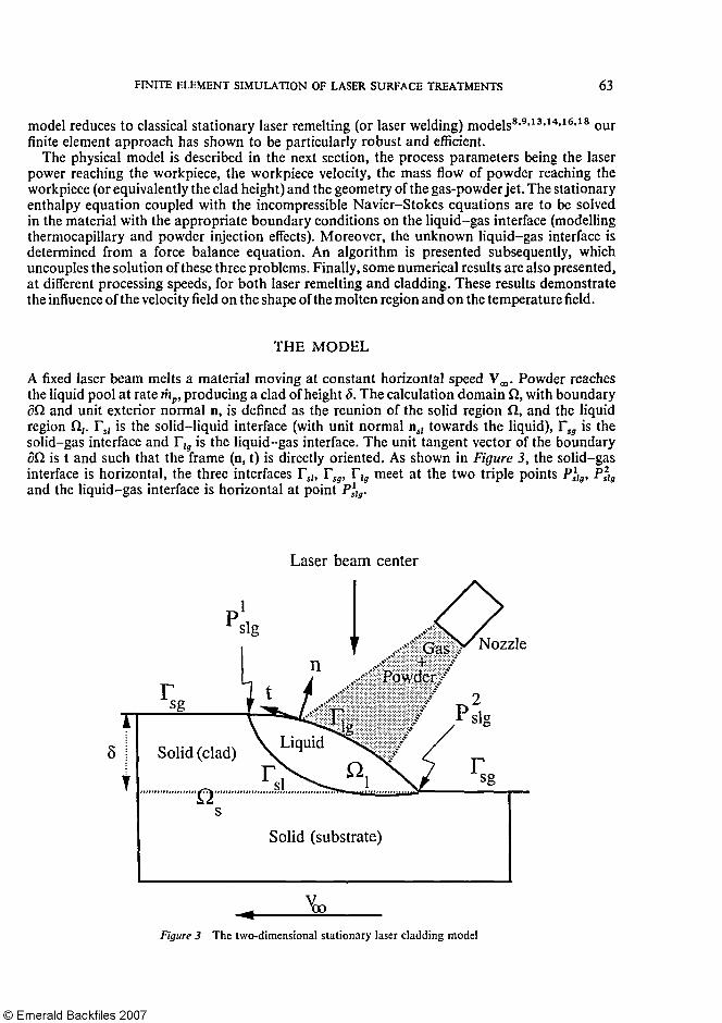
A fixed laser beam melts a material moving at constant horizontal speed V∞. Powder reaches the liquid pool at rate , producing a clad of height δ. The calculation domain Ω, with boundary ∂Ω and unit exterior normal n, is defined as the reunion of the solid region ft, and the liquid region Ω1. Γs1 is the solid-liquid interface (with unit normal ns1 towards the liquid), Γsg is the solid-gas interface and Γlg is the liquid-gas interface. The unit tangent vector of the boundary ∂Ω is t and such that the frame (n, t) is directly oriented. As shown in Figure 3, the solid-gas interface is horizontal, the three interfaces Γs1, Γsg, Γlg meet at the two triple points P1slg, P2slg and the liquid-gas interface is horizontal at point P1slg.
64 M. PICASSO AND A. F. A. HOADLEY
This model pertains to a two-dimensional laser cladding situation, stationary in a reference frame attached to the laser beam. The two-dimensional assumption corresponds to a situation where the laser beam, the gas-powder jet and the workpiece transverse dimensions are large compared to the other dimensions. The stationary assumption is relevant when the workpiece dimensions are large compared to the dimensions of the calculation domain ft and when instabilities in the molten region are neglected (see for instance Reference 20 for a discussion concerning instabilities of the molten pool in the case of laser remelting). Contrary to Reference 19, the powder is assumed to melt instantaneously on the liquid-gas interface. It is then convected by the velocity field and mixes with the other liquid. Moreover, in order to simplify the presentation of the model, the clad and the substrate are assumed to be made out of the same material, a pure metal or a eutectic alloy, exhibiting a plane solid-liquid interface.
In the sequel, the whole process is split in two different problems: • The thermal or phase-change problem which consists in seeking the temperature T in the
calculation domain Ω and the shape and position of the solid-liquid interface. As usual22-27
an enthalpy formulation is used in order to avoid tracking the solid-liquid interface. • The hydrodynamic problem with unknowns the velocity v1 in the liquid region Ω1 (the
velocity in the solid being of course reduced to the workpiece speed V∞) and the liquid-gas interface shape and position.
The behaviour of the above unknowns are governed by the three conservation laws for mass, momentum and energy, applied on any arbitrary domain contained in Ω. The complete resulting set of equations and boundary conditions is now presented.
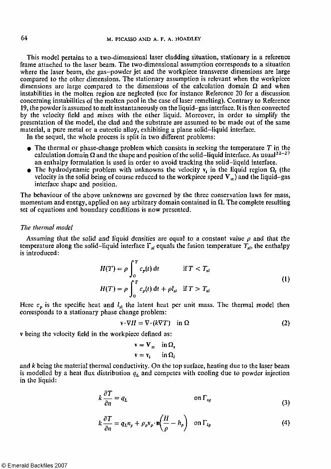
The thermal model Assuming that the solid and liquid densities are equal to a constant value p and that the
temperature along the solid-liquid interface Γsl equals the fusion temperature Tsl, the enthalpy is introduced:
(1)
Here cp is the specific heat and lsl the latent heat per unit mass. The thermal model then corresponds to a stationary phase change problem:
(2) v being the velocity field in the workpiece defined as:
and k being the material thermal conductivity. On the top surface, heating due to the laser beam is modelled by a heat flux distribution qL and competes with cooling due to powder injection in the liquid:
(3)
(4)
FINITE ELEMENT SIMULATION OF LASER SURFACE TREATMENTS 65
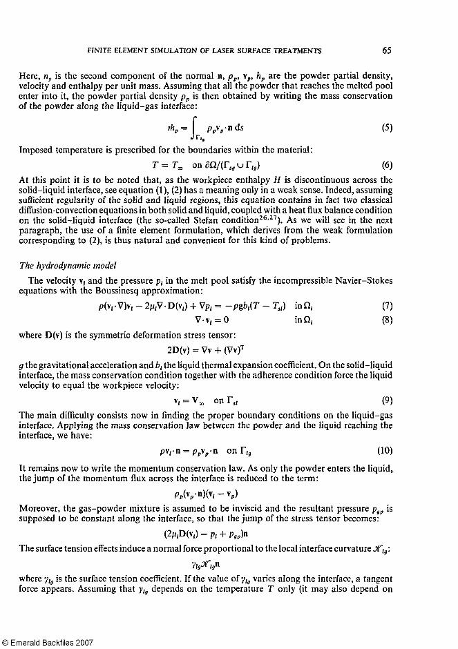
Here, ny is the second component of the normal n, pp, vp, hp are the powder partial density, velocity and enthalpy per unit mass. Assuming that all the powder that reaches the melted pool enter into it, the powder partial density pp is then obtained by writing the mass conservation of the powder along the liquid-gas interface:
(5)
Imposed temperature is prescribed for the boundaries within the material: (6)
At this point it is to be noted that, as the workpiece enthalpy H is discontinuous across the solid-liquid interface, see equation (1), (2) has a meaning only in a weak sense. Indeed, assuming sufficient regularity of the solid and liquid regions, this equation contains in fact two classical diffusion-convection equations in both solid and liquid, coupled with a heat flux balance condition on the solid-liquid interface (the so-called Stefan condition26,27). As we will see in the next paragraph, the use of a finite element formulation, which derives from the weak formulation corresponding to (2), is thus natural and convenient for this kind of problems.
The hydrodynamic model The velocity v, and the pressure p1 in the melt pool satisfy the incompressible Navier-Stokes
equations with the Boussinesq approximation:
(7) (8)
where D(v) is the symmetric deformation stress tensor:
g the gravitational acceleration and b1 the liquid thermal expansion coefficient. On the solid-liquid interface, the mass conservation condition together with the adherence condition force the liquid velocity to equal the workpiece velocity:
(9) The main difficulty consists now in finding the proper boundary conditions on the liquid-gas interface. Applying the mass conservation law between the powder and the liquid reaching the interface, we have:
(10)
It remains now to write the momentum conservation law. As only the powder enters the liquid, the jump of the momentum flux across the interface is reduced to the term:
Moreover, the gas-powder mixture is assumed to be inviscid and the resultant pressure pgp is supposed to be constant along the interface, so that the jump of the stress tensor becomes:
The surface tension effects induce a normal force proportional to the local interface curvature. lg:
where ylg is the surface tension coefficient. If the value of ylg varies along the interface, a tangent force appears. Assuming that ylg depends on the temperature T only (it may also depend on
66 M. PICASSO AND A. F. A. HOADLEY
the concentration if the liquid is a binary alloy), this force is given by:
The momentum conservation law, projected on both normal and tangent directions, thus writes:
(11)
(12)
where the liquid normal and tangent stresses are defined by:
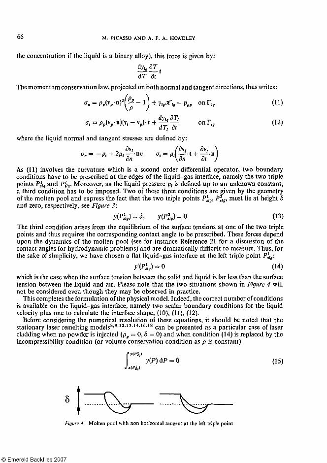
As (11) involves the curvature which is a second order differential operator, two boundary conditions have to be prescribed at the edges of the liquid-gas interface, namely the two triple points P1slg and P2slg. Moreover, as the liquid pressure p1 is defined up to an unknown constant, a third condition has to be imposed. Two of these three conditions are given by the geometry of the molten pool and express the fact that the two triple points P1slg, P2slg, must lie at height 5 and zero, respectively, see Figure 3:
(13) The third condition arises from the equilibrium of the surface tensions at one of the two triple points and thus requires the corresponding contact angle to be prescribed. These forces depend upon the dynamics of the molten pool (see for instance Reference 21 for a discussion of the contact angles for hydrodynamic problems) and are dramatically difficult to measure. Thus, for the sake of simplicity, we have chosen a flat liquid-gas interface at the left triple point P1slg:
(14) which is the case when the surface tension between the solid and liquid is far less than the surface tension between the liquid and air. Please note that the two situations shown in Figure 4 will not be considered even though they may be observed in practice.
This completes the formulation of the physical model. Indeed, the correct number of conditions is available on the liquid-gas interface, namely two scalar boundary conditions for the liquid velocity plus one to calculate the interface shape, (10), (11), (12).
Before considering the numerical resolution of these equations, it should be noted that the stationary laser remelting models8,9,12,13,14,16,18 can be presented as a particular case of laser cladding when no powder is injected (pp — 0, δ = 0) and when condition (14) is replaced by the incompressibility condition (or volume conservation condition as p is constant)
(15)
FINITE ELEMENT SIMULATION OF LASER SURFACE TREATMENTS 67
In the case of laser remelting (or welding), experimental observations have shown that the liquid-gas free surface oscillates during the treatment, thus requiring a time dependent simulation20. In that case, conditions (13) and (15) must be replaced by physical conditions involving contact angles21
NUMERICAL RESOLUTION
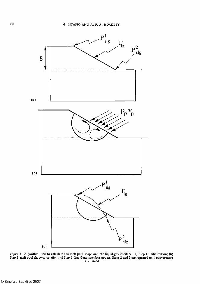
In order to solve the coupled set of equations (1)—(12) corresponding to both thermal and hydrodynamic problems, an iterative technique has been developed. The strategy is as follows and is illustrated in Figure 5. STEP 1: initialization Given the mass flow rate of powder reaching the melted pool mp, the fixed clad height δ is computed by mass conservation of the total amount of powder involved in the process (mp = pV∞δ). An initial guess of the liquid-gas interface shape Γlg is given. STEP 2: melt pool shape computation The powder partial densities pp, is computed with (5). The coupled enthalpy and Navier-Stokes equations are solved. The boundary conditions prescribed on the liquid-gas interface, relative to the Navier-Stokes equations are equations (10) and (12). STEP 3: liquid-gas interface update The new triple points x1slg, x2slg being found, the liquid normal traction σn is calculated and the liquid-gas interface shape Γlg is updated with (11). STEP 4: convergence Steps 2 and 3 are repeated until the relative change on the surface shape is less than a preset value, normally 10 -5. It is clear that the major task consists in solving, for a given liquid-gas interface, both enthalpy and Navier-Stokes equations (step 2). In order to uncouple these two equations, the following strategy is used:
(i) For a given velocity field, the stationary enthalpy (1) is first solved. (ii) Then, for a given enthalpy, the velocity field is updated by performing one time step of
the evolutive Navier-Stokes equations corresponding to (7). Each of these two points are discussed in detail in the next two sub-sections, the last
sub-section being devoted to the calculation of the liquid-gas interface (step 3).
The enthalpy equation Equations (1) and (2) are first rewritten as a Stefan problem22,23,26,27. Introducing the
Kirshoff transformation K: R → R defined by:
and the real increasing function β defined by:
then equations (1), (2) can be rewritten as a stationary Stefan-like problem: (16) (17)
68 M. PICASSO AND A. F. A. HOADLEY

FINITE ELEMENT SIMULATION OF LASER SURFACE TREATMENTS 69
The boundary conditions (3), (4), (6) now are:
(18)
(19)
(20)
In the particular case when the specific heat cp and the thermal conductivity k are constant in each phase, the expression of the function β reduces to:
Hsl being an arbitrary reference enthalpy (the β function can be arbitrarily shifted along the x-axis). The solution of (16), (17) is obtained by solving the corresponding evolutive equation until the stationary solution is reached, with an algorithm proposed and studied by Magenes, Nochetto and Verdi27-29 modified in the present context to incorporate strong convection fields. Let H° be a first guess of the solution, τ be a time step and ω a relaxation parameter satisfying 0 < ω < l/max(β'(X)). The following scheme is repeated until convergence: For n = 0,1, 2, 3 , . . . find θn+1: Ω → R such that
(21)
and then set (22)
For any h > 0, let Qh be a mesh of Ω in quadrangles with side less than h (in fact the quadrangles will be used to compute the velocity field). Each quadrangle is cut along one diagonal into two triangles and Th denotes the corresponding mesh. The space discretization is done by approximating the enthalpy Hn+1 and the modified temperature θn+1 with continuous piecewise linear functions on these triangles. We thus need to introduce the discrete space
and the corresponding local interpolant, linear on each triangle. The weak formulation corresponding to (21) with the boundary conditions (18), (19) and (20)
70 M. PICASSO AND A. F. A. HOADLEY
is then:
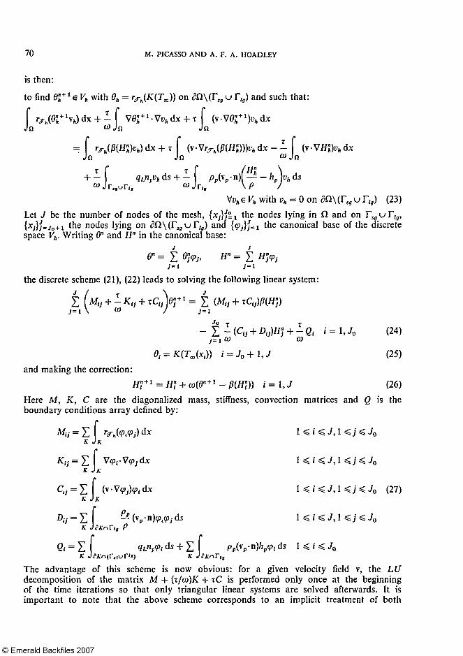
to find with θh = on ∂Ω\ and such that:
Let J be the number of nodes of the mesh, the nodes lying in Ω and on , the nodes lying on and the canonical base of the discrete
space Vh. Writing θn and Hn in the canonical base:
the discrete scheme (21), (22) leads to solving the following linear system:
(24)
(25) and making the correction:
(26) Here M, K, C are the diagonalized mass, stiffness, convection matrices and Q is the boundary conditions array defined by:
(27)
The advantage of this scheme is now obvious: for a given velocity field v, the LU decomposition of the matrix M + (τ/ω)K + τC is performed only once at the beginning of the time iterations so that only triangular linear systems are solved afterwards. It is important to note that the above scheme corresponds to an implicit treatment of both
FINITE ELEMENT SIMULATION OF LASER SURFACE TREATMENTS 71
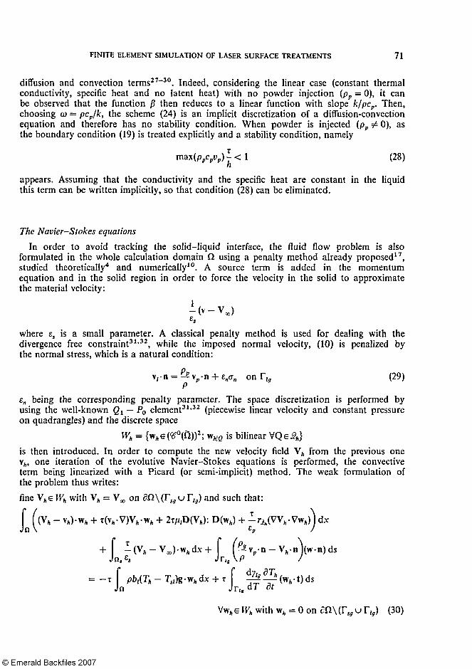
diffusion and convection terms27-30. Indeed, considering the linear case (constant thermal conductivity, specific heat and no latent heat) with no powder injection (pp = 0), it can be observed that the function β then reduces to a linear function with slope k/pcp. Then, choosing ω = pcp/k, the scheme (24) is an implicit discretization of a diffusion-convection equation and therefore has no stability condition. When powder is injected (pp ≠ 0), as the boundary condition (19) is treated explicitly and a stability condition, namely
(28)
appears. Assuming that the conductivity and the specific heat are constant in the liquid this term can be written implicitly, so that condition (28) can be eliminated.
The Navier-Stokes equations In order to avoid tracking the solid-liquid interface, the fluid flow problem is also
formulated in the whole calculation domain Ω using a penalty method already proposed17, studied theoretically4 and numerically10. A source term is added in the momentum equation and in the solid region in order to force the velocity in the solid to approximate the material velocity:
where ΕS is a small parameter. A classical penalty method is used for dealing with the divergence free constraint31,32, while the imposed normal velocity, (10) is penalized by the normal stress, which is a natural condition:
(29)
εn being the corresponding penalty parameter. The space discretization is performed by using the well-known Q1 — P0 element31,32 (piecewise linear velocity and constant pressure on quadrangles) and the discrete space
is then introduced. In order to compute the new velocity field Vh from the previous one vh, one iteration of the evolutive Navier-Stokes equations is performed, the convective term being linearized with a Picard (or semi-implicit) method. The weak formulation of the problem thus writes: fine VhεWh with Vh = V∞ on ∂Ω\(Γsg u Γlg) and such that:

72 M. PICASSO AND A. F. A. HOADLEY
Here Th is the discrete temperature:
and Ωs is the discrete solid region: (31)
Streamline upwind is performed for both the enthalpy and Navier-Stokes equations33
Normal traction and interface calculation After the velocity field has been computed, the normal traction of the liquid σn is
calculated from (29). A suitable system of coordinates is chosen in order to formulate (11) as a differential equation. More precisely, the interface Tlg is parametrised by a function:
where xlslg and x2slg are the left and right x-coordinates of the two triple points guessed as in Figure 5. The curvature can be then expressed as the second order differential operator:
Let F: → R be a function containing all the calculated terms in (11):
As mentioned previously, the liquid pressure p1 contained in the normal stress σn, is defined up to an unknown constant C, so the free surface problem is now to find the parameterization:
→ R and the constant CεR satisfying the second order differential equation:
(32) together with the three conditions (13), (14):
(33) In the case of stationary laser remelting (no powder injection, δ = pp = 0) the last condition in the above equation must be replaced by equation (15) which writes:
A modified Newton method is used7 to solve (32). Only the derivative of the curvature with respect to y1g is computed. Indeed, the derivatives of the liquid normal stress, powder momentum and mixture pressure are avoided. At each Newton iteration, the parametrization
is thus obtained from the previous one by solving the following problem: find satisfying the boundary conditions (33) and CεR such that:
(34)
FINITE ELEMENT SIMULATION OF LASER SURFACE TREATMENTS 7 3
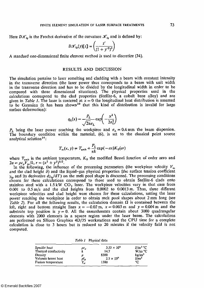
Here is the Frechet derivative of the curvature and is defined by:
A standard one-dimensional finite element method is used to discretize (34).
RESULTS AND DISCUSSION
The simulation pertains to laser remelting and cladding with a beam with constant intensity in the transverse direction (the laser power thus corresponds to a beam with unit width in the transverse direction and has to be divided by the longitudinal width in order to be compared with three dimensional situations). The physical properties used in the calculations correspond to the clad properties (Stellite-6, a cobalt base alloy) and are given in Table 1. The laser is centered at x = 0 the longitudinal heat distribution is assumed to be Gaussian (it has been shown20 that this kind of distribution is invalid for large surface deformation):
PL being the laser power reaching the workpiece and σL = 0.4 mm the beam dispersion. The boundary condition within the material, (6), is set to the classical point source analytical solution34:
where Tamb is the ambient temperature, K0 the modified Bessel function of order zero and 2a = pcpV∞/k,r = (x2 + y2)1/2.
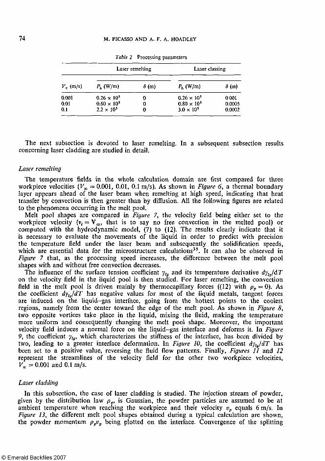
In the following, the influence of the processing parameters (the workpiece velocity V∞ and the clad height 5) and the liquid-gas physical properties (the surface tension coefficient ylg and its derivative dy,lg/dT) on the melt pool shape is discussed. The processing conditions chosen for these calculations correspond to those used to obtain Stellite-6 clads onto stainless steel with a 1.5 kW CO2 laser. The workpiece velocities vary in that case from 0.001 to 0.5 m/s and the clad heights from 0.0002 to 0.0013 m. Thus, three different workpiece velocities and clad height were chosen for these calculations, setting the laser power reaching the workpiece in order to obtain melt pool shapes about 2 mm long (see Table 2). For all the following results, the calculation domain Ω is contained between the left, right and bottom straight lines x= -0.02 m, x = 0.003 m and y- 0.004 m and the substrate top position is y = 0. All the enmeshments contain about 3000 quadrangular elements with 2000 elements in a square region under the laser beam. The calculations are performed on Silicon Graphics 4D/35 workstations and the CPU time for a complete calculation is close to 3 hours but is reduced to 20 minutes if the velocity field is not computed.
Table I Physical data
Specific heat Thermal conductivity Density Volumic latent heat Fusion temperature
Pcp k P Plsl
3.53 x 10⁶
14.7 8380
2.5 x 10⁹
1300
J /m 3 °C W/m°C kg/m3
J/m3
°C
74 M. PICASSO AND A. F. A. HOADLEY
Table 2 Processing parameters
Vx (m/s)
0.001 0.01 0.1
Laser remelting
PL (W/m)
0.26 x 10⁵
0.60 x 10⁵
2.2 x 10⁵
δ (m)
0 0 0
Laser classing
PL (W/m) δ (m)
0.26 x 10⁵ 0001 0.80 x 10⁵ 0.0005 3.0 x 10⁵ 0.0002
The next subsection is devoted to laser remelting. In a subsequent subsection results concerning laser cladding are studied in detail.
Laser remelting The temperature fields in the whole calculation domain are first compared for three
workpiece velocities (V∞ — 0.001, 0.01, 0.1 m/s). As shown in Figure 6, a thermal boundary layer appears ahead of the laser beam when remelting at high speed, indicating that heat transfer by convection is then greater than by diffusion. All the following figures are related to the phenomena occurring in the melt pool.
Melt pool shapes are compared in Figure 7, the velocity field being either set to the workpiece velocity (v1 = V∞, that is to say no free convection in the melted pool) or computed with the hydrodynamic model, (7) to (12). The results clearly indicate that it is necessary to evaluate the movements of the liquid in order to predict with precision the temperature field under the laser beam and subsequently the solidification speeds, which are essential data for the microstructure calculations35. It can also be observed in Figure 7 that, as the processing speed increases, the difference between the melt pool shapes with and without free convection decreases.
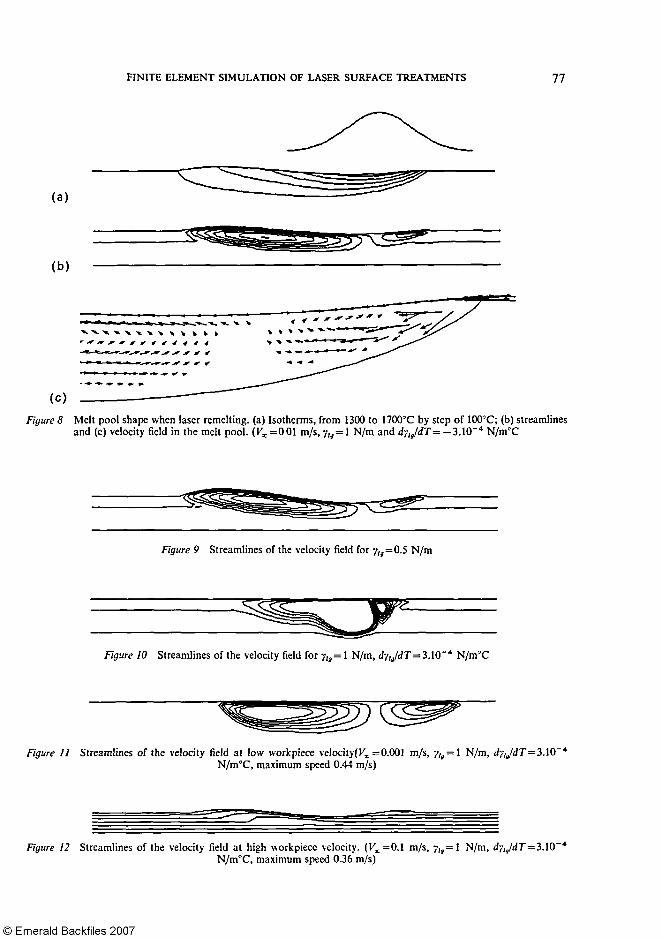
The influence of the surface tension coefficient ylg and its temperature derivative dy,lg/dT on the velocity field in the liquid pool is then studied. For laser remelting, the convection field in the melt pool is driven mainly by thermocapillary forces ((12) with pp = 0). As the coefficient dylg/dT has negative values for most of the liquid metals, tangent forces are induced on the liquid-gas interface, going from the hottest points to the coolest regions, namely from the center toward the edge of the melt pool. As shown in Figure 8, two opposite vortices take place in the liquid, mixing the fluid, making the temperature more uniform and consequently changing the melt pool shape. Moreover, the important velocity field induces a normal force on the liquid-gas interface and deforms it. In Figure 9, the coefficient ylg, which characterizes the stiffness of the interface, has been divided by two, leading to a greater interface deformation. In Figure 10, the coefficient dylg/dT has been set to a positive value, reversing the fluid flow patterns. Finally, Figures 11 and 12 represent the streamlines of the velocity field for the other two workpiece velocities, V∞ = 0.001 and 0.1 m/s.
Laser cladding In this subsection, the case of laser cladding is studied. The injection stream of powder,
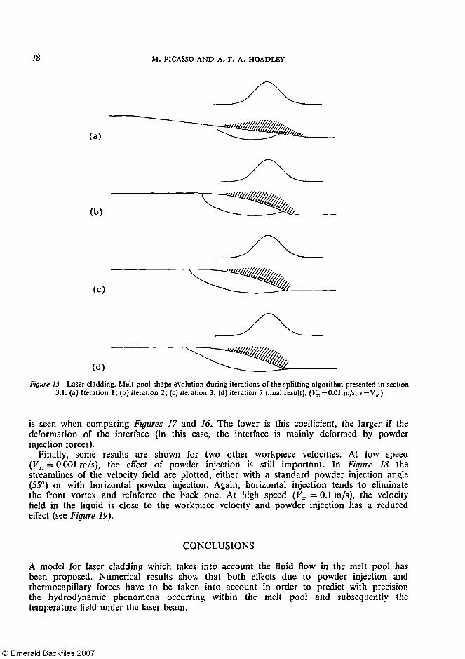
given by the distribution law pp, is Gaussian, the powder particles are assumed to be at ambient temperature when reaching the workpiece and their velocity vp equals 6 m/s. In Figure 13, the different melt pool shapes obtained during a typical calculation are shown, the powder momentum ppvp being plotted on the interface. Convergence of the splitting

FINITE ELEMENT SIMULATION OF LASER SURFACE TREATMENTS 75
algorithm discussed takes about 7 to 15 iterations whether the hydrodynamic calculations are performed or not.
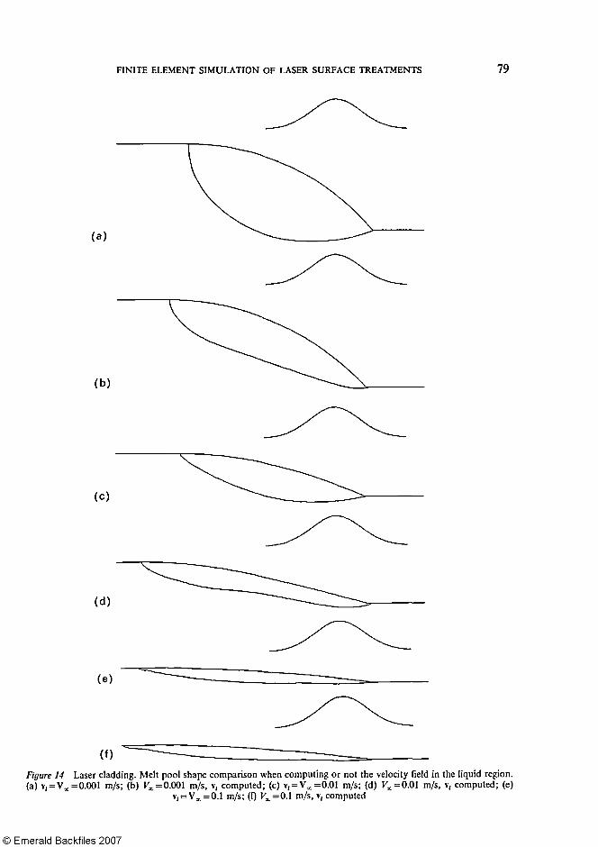
In Figure 14, melt pool shapes are compared, the velocity field in the liquid being either reduced to the workpiece velocity or computed using the hydrodynamic model. The results clearly demonstrate that, as for laser remelting, convection effects in the melt pool cannot be neglected. Nevertheless, the situation is slightly different than in the previous subsection because the fluid flow is not driven only by the thermocapillary effects but also by the forces associated with powder injection. The next figures show the importance of these forces.
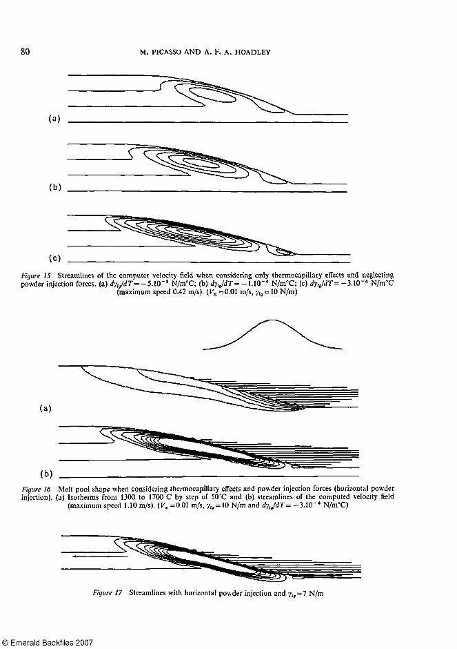
Figure 15 represents the streamlines of the computed velocity field when neglecting the tangent forces induced by powder injection, that is to say the term pp(vp·n)(v1 — vp)·t in (12). As for laser remelting, the fluid flow is then driven by thermocapillary forces and two opposite vortices take place, centered on the hottest point of the melt pool.
Figure 16 represents the temperature and the streamlines of the compound velocity field

76 M. PICASSO AND A. F. A. HOADLEY
when tangent forces due to powder injection are added (the powder momentum ppvp being plotted on the liquid-gas interface). For that particular case, powder was injected horizontally, inducing an important shear stress and stretching the melt pool. The front vortex present in Figure 15 tends to be eliminated, whereas the back vortex is amplified.
The effect of the surface tension coefficient ylg on the shape of the liquid-gas interface
FINITE ELEMENT SIMULATION OF LASER SURFACE TREATMENTS 77
78 M. PICASSO AND A. F. A. HOADLEY
is seen when comparing Figures 17 and 16. The lower is this coefficient, the larger if the deformation of the interface (in this case, the interface is mainly deformed by powder injection forces).
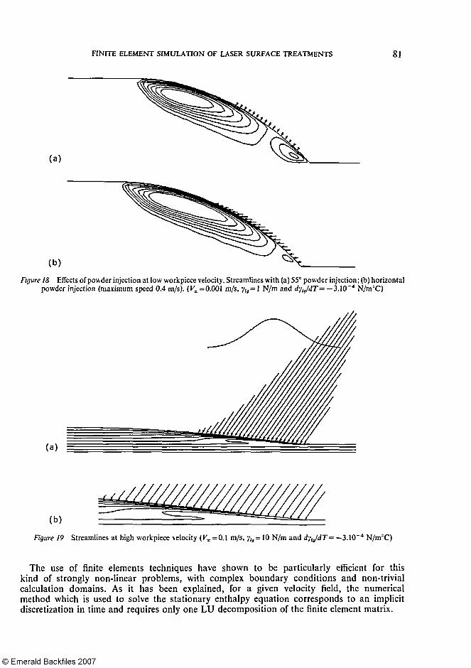
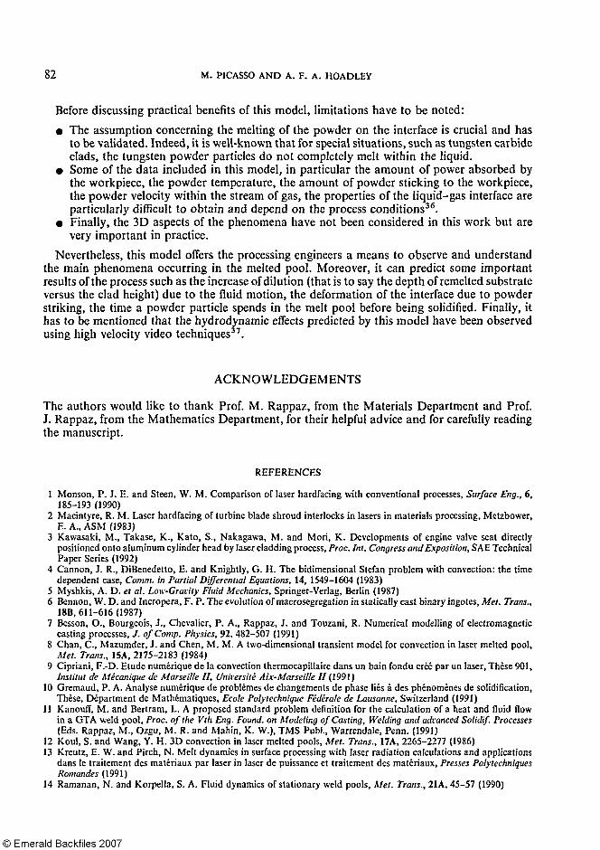
Finally, some results are shown for two other workpiece velocities. At low speed (V∞ = 0.001 m/s), the effect of powder injection is still important. In Figure 18 the streamlines of the velocity field are plotted, either with a standard powder injection angle (55°) or with horizontal powder injection. Again, horizontal injection tends to eliminate the front vortex and reinforce the back one. At high speed (V∞ = 0.1 m/s), the velocity field in the liquid is close to the workpiece velocity and powder injection has a reduced effect (see Figure 19).
CONCLUSIONS
A model for laser cladding which takes into account the fluid flow in the melt pool has been proposed. Numerical results show that both effects due to powder injection and thermocapillary forces have to be taken into account in order to predict with precision the hydrodynamic phenomena occurring within the melt pool and subsequently the temperature field under the laser beam.
FINITE ELEMENT SIMULATION OF LASER SURFACE TREATMENTS 79
80 M. PICASSO AND A. F. A. HOADLEY
FINITE ELEMENT SIMULATION OF LASER SURFACE TREATMENTS 81
The use of finite elements techniques have shown to be particularly efficient for this kind of strongly non-linear problems, with complex boundary conditions and non-trivial calculation domains. As it has been explained, for a given velocity field, the numerical method which is used to solve the stationary enthalpy equation corresponds to an implicit discretization in time and requires only one LU decomposition of the finite element matrix.
82 M. PICASSO AND A. F. A. HOADLEY
Before discussing practical benefits of this model, limitations have to be noted: • The assumption concerning the melting of the powder on the interface is crucial and has
to be validated. Indeed, it is well-known that for special situations, such as tungsten carbide clads, the tungsten powder particles do not completely melt within the liquid.
• Some of the data included in this model, in particular the amount of power absorbed by the workpiece, the powder temperature, the amount of powder sticking to the workpiece, the powder velocity within the stream of gas, the properties of the liquid-gas interface are particularly difficult to obtain and depend on the process conditions36.
• Finally, the 3D aspects of the phenomena have not been considered in this work but are very important in practice.
Nevertheless, this model offers the processing engineers a means to observe and understand the main phenomena occurring in the melted pool. Moreover, it can predict some important results of the process such as the increase of dilution (that is to say the depth of remelted substrate versus the clad height) due to the fluid motion, the deformation of the interface due to powder striking, the time a powder particle spends in the melt pool before being solidified. Finally, it has to be mentioned that the hydrodynamic effects predicted by this model have been observed using high velocity video techniques37.
ACKNOWLEDGEMENTS
The authors would like to thank Prof. M. Rappaz, from the Materials Department and Prof. J. Rappaz, from the Mathematics Department, for their helpful advice and for carefully reading the manuscript.
REFERENCES
1 Monson, P. J. E. and Steen, W. M. Comparison of laser hardfacing with conventional processes, Surface Eng., 6, 185-193 (1990)
2 Macintyre, R. M. Laser hardfacing of turbine blade shroud interlocks in lasers in materials processing, Metzbower, E. A., ASM (1983)
3 Kawasaki, M., Takase, K., Kato, S., Nakagawa, M. and Mori, K. Developments of engine valve seat directly positioned onto aluminum cylinder head by laser cladding process, Proc. Int. Congress and Exposition, SAE Technical Paper Series (1992)
4 Cannon, J. R., DiBenedetto, E. and Knightly, G. H. The bidimensional Stefan problem with convection: the time dependent case, Comm. in Partial Differential Equations, 14, 1549-1604 (1983)
5 Myshkis, A. D. et at. Low-Gravity Fluid Mechanics, Springer-Verlag, Berlin (1987) 6 Bennon, W. D. and Incropera, F. P. The evolution of macrosegregation in statically cast binary ingotes, Met. Trans.,
18B,611-616(1987) 7 Besson, O., Bourgeois, J., Chevalier, P. A., Rappaz, J. and Touzani, R. Numerical modelling of electromagnetic
casting processes, J. of Comp. Physics, 92, 482-507 (1991) 8 Chan, C , Mazumder, J. and Chen, M. M. A two-dimensional transient model for convection in laser melted pool,
Met. Trans., 15A, 2175-2183 (1984) 9 Cipriani, F.-D. Etude numerique de la convection thermocapillaire dans un bain fondu créé par un laser, Thèse 901,
Institut de Mécanique de Marseille II, Université Aix-Marseille II (1991) 10 Gremaud, P. A. Analyse numérique de problèmes de changements de phase liés à des phénomènes de solidification,
These, Department de Mathématiques, Ecole Polytechnique Fédérate de Lausanne, Switzerland (1991) 11 Kanouff, M. and Bertram, L. A proposed standard problem definition for the calculation of a heat and fluid flow
in a GTA weld pool, Proc. of the Vth Eng. Found. on Modeling of Casting, Welding and advanced Solidif. Processes (Eds. Rappaz, M., Ozgu, M. R. and Mahin, K. W.), TMS Publ., Warrendale, Penn. (1991)
12 Koul, S. and Wang, Y. H. 3D convection in laser melted pools, Met. Trans., 17A, 2265-2277 (1986) 13 Kreutz, E. W. and Pirch, N. Melt dynamics in surface processing with laser radiation calculations and applications
dans le traitement des matériaux par laser in laser de puissance et traitement des matériaux, Presses Polytechniques Romandes (1991)
14 Ramanan, N. and Korpella, S. A. Fluid dynamics of stationary weld pools, Met. Trans., 21A, 45-57 (1990)
FINITE ELEMENT SIMULATION OF LASER SURFACE TREATMENTS 83
15 Rappaz, M. and Voller, V. Modelling of micro-segregation in solidification processes, Met. Trans., 21 A, 749-743 (1990)
16 Tsai, M. C. and Kou, S. Marangoni convection in weld pools with a free surface, Int. J. Num. Meth. Fluids, 9, 1503-1516 (1989)
17 Voller, V. and Prakash, C. A fixed grid numerical modelling methodology for convection diffusion mushy region phase-change problems, Int. J. Heat Mass Transfer, 30 (8), 1709-1719 (1987)
18 Zacharia, T., David, S. A. and Kraus, H. G. Comp. modeling of stationary gas-tungsten arc weld pools and comparison to stainless steel 304 exp. results, Met. Trans., 22B, 243-257 (1991)
19 Hoadley, A. F. A. and Rappaz, M. A thermal model of laser cladding by powder injection, Met. Trans., 23B, 631-642 (1992)
20 Lin, M. L. and Eager, T. W. Effects of surface depression in GTA welding, Advances in Welding Science and Technology (Ed. S. A. David), ASM Int., pp. 47-51 (1986)
21 Davis, S. H. Contact-line problems in fluid mechanics, J. Appl. Mech., 50, 977-982 (1983) 22 Bell, G. E. Performance of the enthalpy method, Int. J. Heat Mass Transfer, 25 (4), 587-589 (1982) 23 Ciavaldini, J. F. Analyse numérique d'un problème de Stefan à deux phases par une mèthode d'éléments finis, SIAM
J. Num. Anal., 12,464-487 (1975) 24 Crowley, A. B. Numerical solution of Stefan problems, Int. J. Heat Mass Transfer, 21, 215-219 (1978) 25 Dalhuijsen, A. J. and Segal, A. Comparison of finite element techniques for solidification problems, Int. J. Num.
Meth. Eng., 23, 1807-1829 (1986) 26 Lions, J. L. Quelques méthodes de resolution de problèmes aux limites non-linéaires, Ed. Gauthier-Villars, Paris (1969) 27 Paolini, M., Sacchi, G. and Verdi, C. F.E. approximations of singular parabolic problems, Int. J. Num. Meth. Eng.,
26, 1989-2007 (1988) 28 Magenes, E., Nochetto, R. H. and Verdi, C. Error estimates for a linear scheme to approximate nonlinear parabolic
problems, RAIRO Model. Math. Anal. Num., 21, 655-1678 (1987) 29 Nochetto, R. H. and Verdi, C. An efficient linear scheme to approximate parabolic free boundary problems: error
estimates and implementation, Math. Comp., 51, 27-53 (1988) 30 Picasso, M. Simulation numérique des traitements de surface par laser, Thèse, Ecole Polytechnique Fédérate de
Lausanne, Switzerland (1992) 31 Girault, V. and Raviart, P.-A. Finite Element Methods for Navier-Stokes Equations, Springer- Verlag, Berlin (1986) 32 Hughes, T. J. R., Liu, W. K. and Brooks, A. F.E. analysis of incompressible viscous flows by the penalty function
formulation, J. Comp. Phys., 30, 1-60 (1979) 33 Brooks, A. and Hughes, T. J. R. Streamline upwind/Petrov-Galerkine formulations for convection dominated flows,
Comp. Meth. Appl. Mech. Eng., 32, 199-259 (1982) 34 Lancaster, J. F. Metallurgy of Welding, G. Allen and Unwin Publ., London (1990) 35 Hoadley, A. F. A., Rappaz, M. and Zimmermann, M. Heat-flow simulation of laser remelting with experimental
validation, Met. Trans., 22B, 101-109 (1991) 36 Marsden, C. F., Frenk, A. and Wagniere, J.-D. Proceedings of the ECLAT 92 Conference, Gottingen, Germany, B.
L. Mordike, D.G.M., Oberursel, Germany (1992) 37 Bieler, H. W. Schmelzbaddynamik bei der Oberflachenbehandlung mit CO2 laserstrahlung, Thesis, Lehrstuhl fur
lasertechnik RWTH, Aachen (1989)