Embed Size (px)
Citation preview

FINITE ELEMENT MODELLING TO ASSESS THE EFFECTS OF THE MICROSTRUCTURE TOPOLOGY ON THE FRACTURE TOUGHNESS
OF DUAL-PHASE AUSTEMPERED DUCTILE IRON
Adrián Cisilino, Alejandro Basso, Ricardo Martínez, Marcos San Martín and Jorge Sikora
INTEMA, Facultad de Ingeniería, Universidad Nacional de Mar del Plata – CONICET. Av. Juan B. Justo 4302, 7600 Mar del Plata, Argentina, [email protected], http://www.intema.gov.ar
Keywords: Ductile iron, Fracture toughness, Cohesive Elements.
Abstract. The engineering community is strongly pressed to produce lighter, stronger and stiffer metallic parts. Ductile Iron (DI) can be a material of choice to fabricate numerous parts, since it is suitable to produce high resistance cast parts of complex shape and relatively inexpensive. For this reason DI is used to successfully replace cast and forged steels parts in a large number of applications. The mechanical properties of sound DI cast parts depend mainly on the matrix microstructure (type, amount and distribution of microconstituents), the graphite phase and the cast defects present mainly in the last to freeze (LTF) regions. A wide range of microstructures, and consequently mechanical properties, can be obtained by using different heat treatments. The effects of the microstructure topology on the fracture toughness of dual-phase austempered ductile iron are studied in this paper by means of finite element modelling and experimental testing. To this end, specimens with matrix microstructures ranging from fully ferrite to fully ausferrite were prepared and the crack propagation path studied for each microstructure by means of fractographic analyses. The preferential zones and phases for crack propagation were identified in every case. Based on the experimental observations it was proposed that the ausferrite phase plays the role of reinforcement of the ferritic matrix via the encapsulation of the brittle and weak LTF zones. The crack behaviour was analyzed by means of finite elements via a series of two-dimensional finite element models for the material microstructure in the vicinity of the crack tip. The models were designed to mimic the different microstructures containing the graphite nodules, the LTF zones and the ausferrite encapsulations. The finite element models were discretized using 3-node linear triangular elements. The triangular elements were connected to each other using 4-node cohesive elements which account for material damage and crack propagation in every region of the model. A number of models discretized using regular and irregular meshes were solved in order to study the model convergence and to verify the independence of the results on the mesh geometry. The models were solved using Abaqus/Explicit running on a Beowulf Cluster with 8 Pentium 4 PCs. The correlation between the crack path results computed via the finite elements models and those observed in the experimental analyses was found very good. The numerical results allow confirming the effectiveness of the ausferrite LTF zones. The toughening mechanism is consequence of the increment in the crack path longitude as it avoids the encapsulated LTF zones.
Mecánica Computacional Vol XXVIII, págs. 935-954 (artículo completo)Cristian García Bauza, Pablo Lotito, Lisandro Parente, Marcelo Vénere (Eds.)
Tandil, Argentina, 3-6 Noviembre 2009
Copyright © 2009 Asociación Argentina de Mecánica Computacional http://www.amcaonline.org.ar

1 INTRODUCTION
The engineering community is strongly pressed to produce lighter, stronger and stiffer metallic parts. Ductile Iron (DI) can be a material of choice to fabricate numerous parts, since it is suitable to produce high resistance cast parts of complex shape and relatively inexpensive. For this reason DI is used to successfully replace cast and forged steels parts in a large number of applications (Ductile Iron Data for Design Engineers, 1990). The mechanical properties of sound DI cast parts depends mainly on the matrix microstructure (type, amount and distribution of microconstituents), the graphite phase and the cast defects present mainly in the last to freeze (LTF) regions. A wide range of microstructures, and consequently mechanical properties, can be obtained by using different heat treatments (ASM Handbook, 1992).
Currently, DI producers work in the continuous improvement of DI properties while seeking for new applications. In particular, the market of safety critical parts in the automotive industry is a main target where high strength and toughness are customary requirements. In this regard special thermal cycles have been developed in order to obtain mixed microstructures. Wade et al (1981), He et al (1997) and Rashidi et (2000) al have obtained mixed microstructures starting from rapid uncompleted austenitisations into the austenitic field. The austenite nucleated mainly surrounding graphite nodules is transformed into pearlite, bainite or martensite depending on the cooling rate. The final phases obtained consisted of ferrite and pearlite, bainite or martensite. The relationship between the relative quantities of each phase is controlled by means of the austentising time (the longer the time, the higher the amount of austenite in the matrix).
A new kind of DI usually referred to as dual-phase Austempered Ductile Iron (dual-phase ADI) is an active field of research and development. The matrix of dual-phase ADI is composed of ausferrite (regular ADI microstructure) and free (or allotriomorphic) ferrite which is obtained by subjecting DI to special heat treatments. Different methodologies have been used to obtain this kind of microstructures. Aranzabal et al (2002) obtained dual-phase ADI by means of changes in the chemical composition of the melt by heat treating ferritic DI at different austenitising temperatures. In that process the austenitising stage is followed by an austempering step in order to obtain a final microstructure composed by ferrite and ausferrite. On the other hand, Wade et al (1981) and Verdu et al (2005) have obtained dual-phase ADI microstructures by means of heat treatments similar to those used by He et al (1997) and Rashidi et (2000), based in quick and uncompleted austenitisations in the austenitic field. However, in these cases the austenite obtained at high temperature is transformed into ausferrite as a result of an austempering step. An alternative methodology to obtain dual-phase ADI has been used by Basso et al (2007) and Kilicli et al (2007). This methodology consists in an incomplete austenitisation stage at temperatures within the intercritical interval followed by an austempering step in a salt bath to transform the austenite into ausferrite. This heat treatment has been allowed to obtain microstructures composed of different combinations of free ferrite and ausferrite, depending on the austenitising temperature. The main characteristic of this material is the improvement of the fracture and fatigue properties by controlling the relative amount of the present phases and their morphologies.
2 ROLE OF MIXED MICROSTRUCTURES ON MECHANCAL PROPERTIES OF DUCTILE IRON
He et al (1997), Rashidi et (2000), Dai et al (2001) and Verdu et al (2005) focused the development of thermal cycles to encapsulate the graphite nodules with different types of
A.P. CISILINO, A. BASSO, R. MARTINEZ, M. SAN MARTIN, J. SIKORA936
Copyright © 2009 Asociación Argentina de Mecánica Computacional http://www.amcaonline.org.ar

microconstituents (pearlite, bainite and martensite) in order to improve mechanical properties. The goal of these authors was to improve the mechanical properties of ferritic DI surrounding graphite nodules (phase with no resistance) with a high resistant second phase. Based on the same tactic, Wade et al (1981) and Verdu et al (2005) have studied the mechanical properties of dual-phase ADI microstructures, encapsulating graphite nodules with ausferrite. They found that the yield stress, tensile strength and hardness increase with increasing the ausferrite volume fraction. In particular, microstructures composed of 80% ferrite and 20% ausferrite allowed reaching increments in tensile strength and fatigue life when compared with fully ferritic DI.
Kilicli et al (2007) have studied the mechanical properties of dual-phase ADI austempered at 365ºC, on a wide range of microstructures composed by different quantities of ferrite and ausferrite. The resulting microstructures exhibited higher ductility than the fully ausferritic ones. In particular, samples with 45% ausferrite and 65% ferrite showed the best combinations of strength and toughness.
Some of the authors of this paper have also contributed in the field of dual-phase ADI, analysing the effect of austempering temperature and other variables on the final material microstructure and properties, focusing particularly on microstructures where the LTF zones are encapsulated by ausferrite (see Basso et al, 2007). These previous results are reported in Table 1 and Figure 1 for tensile and fracture properties respectively. As it can be seen, the fracture toughness, KIC, increases with the ausferrite content. Besides, the crack critical size, defined as the square of the ratio between the fracture toughness and the yield stress, (KIC/σ0.2)2, shows it highest value for dual-phase ADI matrices composed of allotriomorphic ferrite and small amounts of ausferrite (less than 25%). This has been attributed to the encapsulating effect of the ausferrite located around the LTF zones. In fact, these are the regions where the alloying elements with direct segregation tendency concentrates and most of the cast defects, such as inclusions, carbides, pores, etc. are present. These regions are generally weak zones expecting them to be the preferential and fast path for crack propagation.
The promising obtained results motivated the continuity of the research. In this work, numerical and experimental assessments on the effect of the encapsulation of LTF zones on the fracture properties of dual-phase ADI as well as the mechanics of crack propagation are studied.
Matrix σmax [MPa] σ0.2 [MPa] δ [%]
100% ferrite 455 332 26.5 92% ferrite – 8% ausferrite 486 348 26 80% ferrite - 20% ausferrite 521 354 24 50% ferrite – 50% ausferrite 583 389 19.8 35% ferrite – 65% ausferrite 728 410 18 5% ferrite - 95% ausferrite 1054 707 10.8
100% ausferrite 1085 729 10.6 Table 1: Tensile properties for dual-phase ADI compared with ferritic and ausferritic matrices. (austempering
temperature 350ºC). Data from Basso et al (2007).
Mecánica Computacional Vol XXVIII, págs. 935-954 (2009) 937
Copyright © 2009 Asociación Argentina de Mecánica Computacional http://www.amcaonline.org.ar

Figure 1: Fracture properties for dual-phase ADI matrices compared with ferritic and ausferritic matrices (austempering temperature 350ºC). Data from Basso et al (2007).
3 COMPUTATIONAL MODELLING
The effect of the dual-phase microstructure topology on the crack behaviour is studied in this section by means of finite element modelling. An antecedent in this field is the work by Ortiz et al (2001) who used boundary element models and weight-function analyses to study the effect of microcracking on the mechanics of fatigue crack growth in ADI.
The crack behaviour was analyzed by means of a series of two-dimensional finite element models for the material microstructure in the vicinity of the crack tip. The models were designed to mimic the microstructures of the materials which will be described later in Section 4. Typical model geometry is illustrated in Figure 2-a. It consists in a 4 mm×2 mm sample with a central crack of length 2 mm under remote uniaxial tension. As it is shown in Figure 2-a, only one half of the specimen is modelled after assuming symmetry with respect to the direction perpendicular to the crack at its midpoint. Each model contains 113 nodules of diameter 50 μm. The nodules are randomly distributed and they constitute 8% of the sample volume. The LTF zones are idealized of isosceles triangular-shape with dimensions 80 μm base and 40 μm height. Thirty-one LTF zones constituting 5% of the sample volume are randomly distributed over the model domain. The LTF zones are surrounded with a layer of material representing the encapsulations. Two cases were considered for the encapsulation extent: (1) 2.5% and (2) 8.5% of the sample volume. It is worth mentioning that the model does not account for the effect of grain boundaries.
A.P. CISILINO, A. BASSO, R. MARTINEZ, M. SAN MARTIN, J. SIKORA938
Copyright © 2009 Asociación Argentina de Mecánica Computacional http://www.amcaonline.org.ar

(a)
2 mm
2 mm
(b)
LTF nodule
crack
encapsulation
(c)
Figure 2: (a) Model geometry and dimensions; strategies used for the discretization of the FE model: (b) regular and (c) irregular mesh.
Mecánica Computacional Vol XXVIII, págs. 935-954 (2009) 939
Copyright © 2009 Asociación Argentina de Mecánica Computacional http://www.amcaonline.org.ar

Material properties assigned to the different model regions are reported in Table 2. The matrix was assigned an elastoplastic constitutive law with the properties of a fully ferritic DI. The nodules were considered to behave linear-elastic with the properties of bulk graphite. LTF zones were assimilated to pearlite DI in the as-cast condition (this is before the heat treatment) and to ADI after the heat treatment. In order to account for the solidification defects present in LTF zones (microsegregation, porosity, inclusions, etc.), they were assigned the properties of degraded pearlite DI or ADI whether the model represented their conditions before or after the heat treatment respectively. Degraded properties were arbitrarily defined with the yield stress and the fracture energy equal to one third those of regular pearlite DI or ADI respectively. The encapsulations were assigned an elastoplastic constitutive law with the properties of ADI.
Matrix σmax
[MPa] σ0.2 [MPa] δ [%]
100% ferrite 455 332 26.5 92% ferrite – 8% ausferrite 486 348 26 80% ferrite - 20% ausferrite 521 354 24 50% ferrite – 50% ausferrite 583 389 19.8 35% ferrite – 65% ausferrite 728 410 18 5% ferrite - 95% ausferrite 1054 707 10.8
100% ausferrite 1085 729 10.6 Table 2: Material parameters for the model regions. Data from Ductile Iron Data for Design Engineers (1990)
and the Ductile Iron Society (2009).
The finite element models were discretized using 3-node linear triangular elements. The triangles were connected to each other using 4-node cohesive elements. The progressive damage and failure in the cohesive elements is defined in terms of the traction-separation law depicted in Figure 3. Failure mechanism consists of three ingredients:
i. Damage initiation criterion. As the name implies, damage initiation refers to the beginning of degradation of the response of a material point. In this work the damage is assumed to initiate when the following nominal stress ratios (a quadratic interaction function) reaches a value of one (Abaqus option *DAMAGE INITIATION, CRITERION=QUADS):
2 2
0 0 1n s
n s
t tt t
⎛ ⎞ ⎛ ⎞⎜ ⎟ ⎜ ⎟⎜ ⎟ ⎜ ⎟⎝ ⎠ ⎝ ⎠
+ = (1)
where and nt st are the components of the traction vector in the directions normal and tangential to the element direction, and and 00
nt st are the critical values (see Figure 3). The critical traction values used for the different model regions are given in Table 3. For
fragile materials (these are graphite and degraded pearlite) the normal critical traction, , was set equal to the material yield stress, so that no plastic deformation takes place before damage initiation. On the other hand, for ductile materials (ferritic DI and ADI) the normal critical traction was set
0nt
0 1.5n yt σ= . This choice only allows for very small scale plasticity at the initial stages of the crack growth (Li et al, 2003). The values for the tangential critical traction were set for every material 10 0
s nt β −= t , where following Pandolfi et al (2000) the weighting coefficient 0.866β = .
The damage model assumes a linear elastic traction-separation law prior to damage
A.P. CISILINO, A. BASSO, R. MARTINEZ, M. SAN MARTIN, J. SIKORA940
Copyright © 2009 Asociación Argentina de Mecánica Computacional http://www.amcaonline.org.ar

initiation. In this work initial interface stiffness (slope of the line OA in Figure 3) was considered very high (thousand times that of the associated material Young modulus) in order to avoid introducing an extra compliance in the model (or in other words, the critical displacements, in (0 0 0,n sδ δ δ ) Figure 3, were set nearly zero).
( )0 0 0,n st t t
( )0 0 0,n sδ δ δ
A
Gc
B
O ( ),f f fn sδ δ δ
Figure 3: Traction separation law for the cohesive elements.
Interface
Descriptio
n
Max. normal traction
[MPa] 0nt
Max. shear
traction 0
st [MPa]
Mode-I fract.
energy [J/m2]
0nG
Mode-II fract. Energy 0
sG [J/m2]
Matrix-matrix Ferrite 480 554 8320 11090
Nodule-nodule Graphite 60 69 233 310
LTF-LTF Degraded pearlite 200 231 924 1233
Transformed LTF-LTF
Degraded ADI 375 433 2441 3255
Encapsulation ADI-ADI 1125 1299 21970 29300
Table 3: Material parameters for cohesive interfaces.
ii. Damage evolution law. A scalar damage variable, D, represents the overall damage in
the material. It initially has a value of 0 and it monotonically evolves from 0 to 1 upon further loading after the initiation of damage. The stress components of the traction-separation model are affected by the damage according to
Mecánica Computacional Vol XXVIII, págs. 935-954 (2009) 941
Copyright © 2009 Asociación Argentina de Mecánica Computacional http://www.amcaonline.org.ar

(1 ) , 0
,
(1 )
n nn
n
s s
D t tt
t
t D t
⎧ − ≥⎪= ⎨⎪⎩
= −
(2)
where nt and st are the traction components predicted by the elastic traction-separation behavior for the current strains without damage. The second component for the definition of damage evolution is the specification of the nature of the evolution of the damage variable, D, between initiation of damage and final failure (points O and B in Figure 3). In this work it was defined linear softening law using the Abaqus option *DAMAGE EVOLUTION, TYPE=DISPLACEMENT, SOFTENING=LINEAR.
iii. Element removal criterion. The final element failure occurs when the dissipated damage energy equals the fracture energy. Note that the fracture energy equals the area under the traction-separation curve (see Figure 3). The dependence of the fracture energy on the mode mix is defined in this model based on a power law fracture criterion (Abaqus option *DAMAGE EVOLUTION, TYPE=ENERGY,MIXED MODE BEHAVIOR=POWER LAW, POWER=α)
0 0 1n s
n s
G GG G
α α⎛ ⎞ ⎛ ⎞⎜ ⎟ ⎜ ⎟⎜ ⎟ ⎜ ⎟⎝ ⎠ ⎝ ⎠
+ = (3)
where and nG sG are the work done by the traction in the normal and shear directions and and 0
nG 0sG are the critical fracture energies to produce fracture in the normal (mode-I) and
tangential (mode-II) directions respectively. The exponent was set α=1. The critical fracture energy values for the different model regions are reported in Table 3.
Mode-I critical fracture energies for every material were computed using the well-known formula 20
ICn K EG = , while for mode-II 20 0s nG β − ⋅= G where 0.866β = is the weighting
coefficient introduced earlier (see Pandolfi et al, 2000). In order to verify the independence of the results on the mesh size and orientation the
models were discretized using regular and irregular meshes (see Figures 2-b and 2-c respectively) and elements with sizes ranging from 5μm and 8μm. The models were solved for plane stress and plane strain conditions. In every case it was verified that the computed results were independent of the element size, the mesh orientation and the assumption of the plane stress or plain strain condition.
Preliminary tests not reported in this work showed that the material damage occurs in the region next to the crack tip. So that, and in order to reduce the model computational cost, the cohesive elements were only used in the central third of the model (the region delimited by dashed lines in Figure 2-a). Models were solved using Abaqus/Explicit running on a Beowulf Cluster with 8 Pentium 4 PCs. The remote traction load was applied incrementally until the complete failure of the sample using a 500 second-long time step. In every case the appropriate mass scaling procedures were used in order to ensure quasi-static loading conditions. To this end it was verified that the model kinetic energy was always less than 2% the external work. For further details on the model implementation please refer to the Abaqus Theory and Analysis Manuals (2007).
Models were used to study the following microstructure configurations: (a) Ferritic microstructure: ferritic matrix with graphite nodules and LTF zones. (b) Dual-phase ADI case 1: ferritic matrix with graphite nodules and encapsulated LTF
zones. Encapsulation extent: 2.5% of the sample volume.
A.P. CISILINO, A. BASSO, R. MARTINEZ, M. SAN MARTIN, J. SIKORA942
Copyright © 2009 Asociación Argentina de Mecánica Computacional http://www.amcaonline.org.ar

(c) Dual-phase ADI case 2: ferritic matrix with graphite nodules and encapsulated LTF zones. Encapsulation extent: 8.5% of the sample volume.
(d) ADI microstructure: limiting case consisting in a completely ausferritic matrix with graphite nodules and LTF zones.
4 EXPERIMENTAL ANALYSES
It is presented in this section an experimental test devoted to monitor the crack path within the material microstructure. Since it is practically impossible to monitor the crack path during a traction test, the experimental analyses in this section consists in observations performed on stable growing cracks induced by means of cyclic loading. It is worth mentioning that it is not the intention of these analyses to evaluate the material fatigue properties. Although the differences between the mechanisms governing crack propagation for monotonous and cyclic loads, it is expected that the comparison of the propagations paths could provide useful information to better understand the effect of the microstructure on the material fracture toughness.
4.1 Material and sample preparation
A ductile cast iron melt was prepared using a medium frequency induction furnace at an industrial foundry plant (Megafund S.A., Argentina). Copper content was chosen 0.90% in order to improve the material austemperability. The melt was poured in 25mm-thick Y-block-shaped sand moulds. Round and prismatic samples were cut from the Y-blocks and used to prepare test specimens. The chemical composition of the material is listed in Table 4. The as-cast microstructure was pearlitic-ferritic, and the nodularity exceeded 90%, according to the ASTM A-247 standard.
All the samples were firstly ferritised by means of an annealing heat treatment. Four dual-phase ADI microstructures containing different relative quantities of ferrite and ausferrite were obtained by heat treatments. The heat treatments consisted of a partial austenitisation within the intercritical temperature interval at 780 ºC, 800 ºC, 820 ºC and 860 ºC during one hour followed by an austempering at 350 ºC for 90 minutes in all the cases. The intercritical temperature interval for the melt was established by employing the methodology described in previous papers by the authors (Basso et al, 2007).
In addition, samples with entirely ferritic and ausferritic matrices were also produced to be used as references. Standard ADI samples were obtained by means of a heat treatment consisting in a complete austenitising stage at 910 ºC for one hour followed by an austempering at 350 ºC for 90 minutes.
The ferritising and the austenitising treatments were both performed using electric furnaces, while a 500 kg salt bath was used for the austempering. Microconstituents quantification was performed by means optical microscopy and image-processing using the software Image-Pro Plus (1990).
Table 5 shows the identification of the samples, their intercritical austenitisation temperatures and the final percentages of the matrix microconstituents.
Mecánica Computacional Vol XXVIII, págs. 935-954 (2009) 943
Copyright © 2009 Asociación Argentina de Mecánica Computacional http://www.amcaonline.org.ar

%C %Si %Mn %Cu %Mg %S, P %CE
3.35 3.21 0.46 0.94 0.04 < 0.02 4.26
Table 4: Chemical composition of the material (weight %).
Sample Austenitization, T (ºC) Phases in the matrix, %
F ---- 100% ferrite DP1 780 90% ferrite – 10% ausferrite DP2 800 80% ferrite - 20% ausferrite DP3 820 50% ferrite – 50% ausferrite DP4 860 5% ferrite - 95% ausferrite ADI 910 100% ausferrite
Table 5: Sample designation, austenitising temperature and phase percentages.
4.2 Fractographic analyses
Crack propagation tests were performed using single edge notched specimens under bending load, SEN (B), similar to those specified by ASTM E399 for fracture toughness tests. The sample dimensions were: thickness, B = 10 mm; width, W = 20 mm and span, S = 80 mm. The machined notch was 9 mm length and 1.5 mm width, with an angle of 45o (see Figure 4).
Crack propagation was induced by means of displacement-controlled cyclic load by using a mechanical testing machine with a double-eccentric actuator (see Figure 4). A constant eccentricity e = 0.145 mm was chosen for all tests. This eccentricity resulted in stable crack propagation under small scale plasticity condition. To this end it was verified that the crack plastic zone extent, rp, never exceeded 1% the crack length, accordingly to procedures reported in the literature (Anderson, 1994). Cyclic load was applied at a frequency of 6 Hz.
The experimental methodology consisted in: a) to stop the fatigue test periodically, b) to polish the lateral specimen faces, c) to etch the specimen lateral faces with Nital 2%, d) to perform optical microscopic observations, and e) to document the crack propagation length and path by means of micrographs. The stops for observations were performed at intervals of 15 minutes until the sample broke apart.
A.P. CISILINO, A. BASSO, R. MARTINEZ, M. SAN MARTIN, J. SIKORA944
Copyright © 2009 Asociación Argentina de Mecánica Computacional http://www.amcaonline.org.ar

Figure 4: Experimental set up of crack propagation test.
5 RESULTS AND DISCUSSION
5.1 Numerical modelling
Figure 5 illustrates the resulting crack propagation paths for the four modelled microstructures. It can be observed from Figure 5-a that the crack path in the ferritic microstructure follows the LTF zones. On the other hand, for the encapsulated 1 and encapsulated 2 models the crack advances across the ferritic matrix and avoiding the LTF zones (see Figure 5-b and Figure 5-c). The greater the encapsulation extent, the more intricate the resulting crack paths are. Finally, the crack path for the ADI microstructure (see Figure 5-d) is almost identical to that of the ferritic microstructure, since the transformed LTF zones are once again the regions of the model with the weakest fracture properties.
Table 6 reports the failure stress and damage energy results computed for the four configurations. The failure stress is the maximum traction attained by the sample up to the moment the crack propagates across the complete ligament (this is, the sample splits into two parts). The damage energy is the total energy dissipated by the cohesive elements (variable ALLDMD in Abaqus/Explicit) up to the moment of the sample splits into two parts. Both sets of results are reported normalized with respect to the value computed for the ferritic microstructure. The increment in the failure stress for the encapsulated case (1) is 32% with respect to the ferritic matrix, while the increment in the damage energy is nearly 390%. Besides, the encapsulation extent has a marginal effect on the failure stress. The failure stress for the encapsulation case 2 exhibits only an increment of 4% with respect to the case 1. On the other hand, the encapsulation extent has a strong influence on the damage energy which rises 35% with respect to the encapsulation case 1 and up to nearly 530% when compared to that of the ferritic matrix. This result can be justified by the increment in the crack path longitude which avoids the encapsulated LTF zones. Finally, the ADI microstructure results in an important increment of the failure stress (214% larger than that of the ferritic matrix) while it has almost no effect on the damage energy. This last result can be explained arguing that the relative reduction in the longitude of the crack path in the ADI microstructure with respect to the encapsulated cases compensates the increment in the matrix fracture toughness
Mecánica Computacional Vol XXVIII, págs. 935-954 (2009) 945
Copyright © 2009 Asociación Argentina de Mecánica Computacional http://www.amcaonline.org.ar

as it is has been transformed from ferrite to ADI (see Table 2).
(a) Ferritic microstructure (b) Encapsulation case 1
(c) Encapsulation case 2 (d) ADI microstructure
Figure 5: Crack propagation paths for the four FE models.
It is worth to mention that the numerical values for the relative increments or reductions in
the failure stress and damage energy reported in the previous paragraph are only indicative. The computed values depend on the material properties specified to the different model regions (see Table 2 and Table 3) which were not measured for the actual tests specimens but set using the best criteria of the authors. However, the trend of the results can be credited. To this extent it is observed that the numerical results for the damage energy can qualitative explain the trend of the experimental tests reported by Basso et al (2007) and depicted in Figure 1. Starting from a fully ferrite matrix, the increment of the ausferrite content leads to the encapsulation of the LTF zones what results in increments in the fracture energy (see results for the ferrite and encapsulated cases 1 and 2 in Table 6) but has a marginal effect on
A.P. CISILINO, A. BASSO, R. MARTINEZ, M. SAN MARTIN, J. SIKORA946
Copyright © 2009 Asociación Argentina de Mecánica Computacional http://www.amcaonline.org.ar

the σ0.2 (see the σ0.2 data for the 100%, 95% and 80% ferrite samples in Table 1). This behavior can explain the rise in the values of (KIC/σ0.2)2 in Figure 1 when the ausferrite content is incremented from 0% to around 20%. However, this trend for the (KIC/σ0.2)2 is reverted for matrices with high contents of ausferrite forming a continuous austenitic fase in the material microstructure. The change in the crack path behaviour does not result in furher increments in the damage energy (consider as a limiting case the damage energy for the ADI model in Table 6), but there are important improvements in the σ0.2 (see the σ0.2 data for the 33% and 5% ferrite samples in Table 1). As a consequence the (KIC/σ0.2)2 diminishes after an ideal amount of ausferrite is introduced into the material microstructure.
Normalized
failure stress Normalized
damage energy Ferrite microstructure 1.00 1.00 Encapsulation case (1) 1.32 3.89 Encapsulation case (2) 1.36 5.28
ADI microstructure 2.14 5.47
Table 6: Failure traction and damage energy results from the finite element analyses.
5.2 Experimental analyses
The results of the fractographic analyses show that the fracture path of entirely ferritic matrices (samples F) exhibits transgranular propagation (see Figure 6) and it mainly follows LTF zones (see Figure 7 and Figure 8). Zones with high plastic deformation are evident in the fracture path and in its vicinity (see Figure 6). Branching advance of the main crack is also observed (see Figure 8). It can also be seen in Figure 6, Figure 7 and Figure 8 that although the crack crosses several nodules, nodules do not constitute the preferential propagation path.
60μm
Figure 6: Plastic deformation produced by the advancing crack.
Mecánica Computacional Vol XXVIII, págs. 935-954 (2009) 947
Copyright © 2009 Asociación Argentina de Mecánica Computacional http://www.amcaonline.org.ar

60μm
LTF zone
Figure 7: Crack in progress through LTF zones in ferritic matrix.
100μm
100μm
LTF zones
Figure 8: Branched path of fracture in the ferritic matrix.
For samples DP1 (matrices containing approximately 90% ferrite and 10% ausferrite) the ausferrite is located mainly at the LTF zones. It is important to point out that in this case the crack propagates avoiding the ausferrite-encapsulated LTF zones (see Figure 9 and Figure 10). Thus, the crack follows an intricate and transgranular crack path which exhibits zones with noticeable plastic deformation.
Samples DP2 (matrices composed by approximately 80% ferrite and 20% ausferrite) show that an increment in ausferrite content results in larger encapsulation for LTF zones and also the ausferrite starts to be present along the ferrite grain boundaries. Crack propagation is transgranular in the ferritic zones and it follows an intricate path which avoids most of the encapsulated LTF zones (see Figure 11).
For samples DP3 (matrices composed by 50% ferrite and 50% ausferrite) it is found that the crack advances through the ausferrite, which is now located on all the previous ferrite grain boundaries and LTF zones. The plastic deformation observed in these samples has been reduced and the fracture path takes a straighter geometry (see Figure 12).
Figure 13 shows the crack propagation in samples DP4, which has an ausferritic matrix
A.P. CISILINO, A. BASSO, R. MARTINEZ, M. SAN MARTIN, J. SIKORA948
Copyright © 2009 Asociación Argentina de Mecánica Computacional http://www.amcaonline.org.ar

containing small amounts of allotriomorphic ferrite as a dispersed second phase. It is clearly observed that crack propagation avoids the ferrite pools; and as it happened for fully ferritic matrices, the crack chooses LTF as preferential zones to advance. The aspect of the crack in this case is straight and no signs of plastic deformation are evident in the vicinity of the fracture path.
Zonas ausferríticas
100μm
Encapsulated LTFs
Non-Encapsulated LTF
Figure 9: Advancing crack through LTF in sample DP1
Zonas usferríticas
100μm
Encapsulated LTFs
Non-Encapsulated LTF
Figure 10: Crack avoiding LTF zones encapsulated with ausferrite in sample DP1.
Mecánica Computacional Vol XXVIII, págs. 935-954 (2009) 949
Copyright © 2009 Asociación Argentina de Mecánica Computacional http://www.amcaonline.org.ar

100μm
Ausferrite in LTF zones
a)
100μm
Ausferrite in LTF zones
Ausferrite in Grain boundary
100μm
b)
Figure 11: Crack avoiding LTF zones encapsulated with ausferrite in sample DP2.
A.P. CISILINO, A. BASSO, R. MARTINEZ, M. SAN MARTIN, J. SIKORA950
Copyright © 2009 Asociación Argentina de Mecánica Computacional http://www.amcaonline.org.ar

a)
Zona ausferrítica
100μm
Ausferriticzone
Zona ausferrítica
b)
60μm
Ausferriticzone
60μm
Figure 12: Crack advancing through ausferrite in sample DP3.
Mecánica Computacional Vol XXVIII, págs. 935-954 (2009) 951
Copyright © 2009 Asociación Argentina de Mecánica Computacional http://www.amcaonline.org.ar

60μm
Zona LTF LTF zone
60μm
Figure 13: Crack advancing through ausferrite and LTF zones avoiding the ferritic phase in sample DP4.
Although the limitations because of the different propagation mechanisms, the correlation
between the crack paths resulting from the numerical models and observed in the experimental analyses is evident. It is clear that the encapsulations of the LTF zones help the crack to avoid the most brittle and weakest zones into the material microstructure, modifying the fracture path and increasing the resistance to crack propagation.
Table 7 displays the number cycles to fracture for the different test samples. Despite that these values are not the result of conventional fatigue tests it is interesting to compare they behaviour and to correlate them with the other analyses. Thus, it is interesting to observe in Table 7 that the number of cycles-to-break of the DP2 sample (80% ferrite - 20% ausferrite microstructure) doubled those of the other microstructures. Note that both, the maximum time to fracture in Table 7 and the maximum in the (KIC/σ0.2)2 values in Figure 1 are for the specimen with the 80% ferrite - 20% ausferrite microstructure.
On the other hand, the total number of cycles-to-break of the ADI sample was shorter, when compared to the sample DP4 (5% ferrite - 95% ausferrite microstructure). The ductile disperse second phase (ferrite) within a harder phase (ausferrite), makes more difficult the crack growth due to changes in the propagation direction and longer fracture paths for the DP4. These results show the same trend than that of the KIC which is higher for the DP4 specimen than for the ADI one (see Figure 1). This improvement mechanism is called crack deflection, and it can be found in other materials such as ceramics or polymer based composites (Hertzberg, 1989).
A.P. CISILINO, A. BASSO, R. MARTINEZ, M. SAN MARTIN, J. SIKORA952
Copyright © 2009 Asociación Argentina de Mecánica Computacional http://www.amcaonline.org.ar
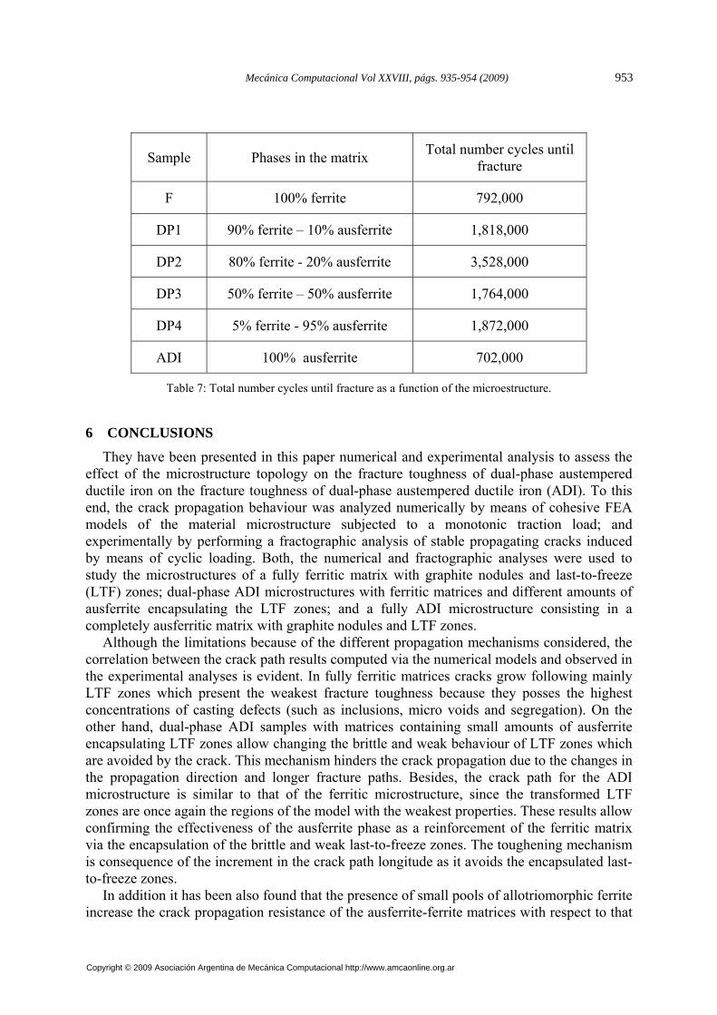
Sample Phases in the matrix Total number cycles until fracture
F 100% ferrite 792,000
DP1 90% ferrite – 10% ausferrite 1,818,000
DP2 80% ferrite - 20% ausferrite 3,528,000
DP3 50% ferrite – 50% ausferrite 1,764,000
DP4 5% ferrite - 95% ausferrite 1,872,000
ADI 100% ausferrite 702,000
Table 7: Total number cycles until fracture as a function of the microestructure.
6 CONCLUSIONS
They have been presented in this paper numerical and experimental analysis to assess the effect of the microstructure topology on the fracture toughness of dual-phase austempered ductile iron on the fracture toughness of dual-phase austempered ductile iron (ADI). To this end, the crack propagation behaviour was analyzed numerically by means of cohesive FEA models of the material microstructure subjected to a monotonic traction load; and experimentally by performing a fractographic analysis of stable propagating cracks induced by means of cyclic loading. Both, the numerical and fractographic analyses were used to study the microstructures of a fully ferritic matrix with graphite nodules and last-to-freeze (LTF) zones; dual-phase ADI microstructures with ferritic matrices and different amounts of ausferrite encapsulating the LTF zones; and a fully ADI microstructure consisting in a completely ausferritic matrix with graphite nodules and LTF zones.
Although the limitations because of the different propagation mechanisms considered, the correlation between the crack path results computed via the numerical models and observed in the experimental analyses is evident. In fully ferritic matrices cracks grow following mainly LTF zones which present the weakest fracture toughness because they posses the highest concentrations of casting defects (such as inclusions, micro voids and segregation). On the other hand, dual-phase ADI samples with matrices containing small amounts of ausferrite encapsulating LTF zones allow changing the brittle and weak behaviour of LTF zones which are avoided by the crack. This mechanism hinders the crack propagation due to the changes in the propagation direction and longer fracture paths. Besides, the crack path for the ADI microstructure is similar to that of the ferritic microstructure, since the transformed LTF zones are once again the regions of the model with the weakest properties. These results allow confirming the effectiveness of the ausferrite phase as a reinforcement of the ferritic matrix via the encapsulation of the brittle and weak last-to-freeze zones. The toughening mechanism is consequence of the increment in the crack path longitude as it avoids the encapsulated last-to-freeze zones.
In addition it has been also found that the presence of small pools of allotriomorphic ferrite increase the crack propagation resistance of the ausferrite-ferrite matrices with respect to that
Mecánica Computacional Vol XXVIII, págs. 935-954 (2009) 953
Copyright © 2009 Asociación Argentina de Mecánica Computacional http://www.amcaonline.org.ar

of the completely ausferritic matrices. This improvement is attributed to the so called crack deflection mechanism.
REFERENCES
Abaqus User Manuals, Version 6.7, Dassault Systèmes, Providence, RI, USA., 2007. Anderson, T. L., Fracture Mechanics. Fundamentals and Applications, CRC Press, Second
edition, 1994. ASM Handbook Vol.1, Ninth edition, 1992. Aranzabal, J., Serramoglia, G. and Rousiere, D., Development of a new mixed (ferritic –
ausferritic) ductile iron for automotive suspension parts. Int. J. Cast Met. Res., 16/1:185-190, 2002.
Basso, A., Martinez, R. and Sikora, J., Influence of austenitising and austempering temperatures on microstructure and properties of dual phase ADI. Mater. Sci. Technology, 23/11:1321-1326, 2007.
Dai, P., He, Z., Zheng, C. and Mao, Z., In-situ SEM observation on the fracture of austempered ductile iron. Materials Science and Engineering: A, 319-321:531-534, 2001.
Ductile Iron Data for Design Engineers. QIT-Fer et Titane Inc., 1990. Ductile Iron Society.
http://www.ductile.org/didata/Section4/4intro.htm#Fracture%20Toughness (last visited 3 of August of 2009).
He, Z.R., Lin, G.X., and Ji, S., Deformation and fracture of cast iron with an optimized microstructure. Materials Characterization, 38:251-258, 1997.
Hertzberg, R.W., Deformation and fracture mechanics of engineering materials. John Wiley & Sons, Inc., Third edition,1989.
Image-Pro Plus 4.5 for Windows. Media Cybernetics Inc., USA (1990). Kilicli, V. and Erdogan, M., Effect of ausferrite volume fraction and morphology on tensile
properties of partially austenitised and austempered ductile irons with dual matrix structures. Int. J. Cast Met., 20/4:202-214, 2007.
Li, H. and Chandra, N., Analysis of crack growth and crack-tip plasticity in ductile materials using cohesive zone models. International Journal of Plasticity, 19/6: 849-882, 2003.
Ortiz, J.E., Cisilino, A.P. and Otegui, J.L., Effect of microcracking on the micromechanics of fatigue crack growth in austempered ductile iron. Fatigue and Fracture of Engineering Materials and Structures, 24/9:591-606, 2001.
Pandolfi, A. and Guduru, P., Three dimensional cohesive-element analysis and experiments of dynamic fracture in C300 steel. International Journal of Solids and Structures, 37/27:3733-3760, 2000.
Rashidi, A. and Moshrefi-Torbati, M., Effect of tempering conditions on the mechanical properties of ductile cast iron with dual matrix structure (DMS). Materials Letters, 45: 203-207, 2000.
Verdu, C., Adrien, J. and Reynaud, A., Contributions of dual phase heat treatments to fatigue properties of SG cast irons. Int. J. Cast Met. Res., 18/6:346-354, 2005.
Wade, N. and Ueda, Y., Mechanical Properties of Ductile Cast Iron with Duplex Matrix. Transactions ISII, 21/2:117-126, 1981.
A.P. CISILINO, A. BASSO, R. MARTINEZ, M. SAN MARTIN, J. SIKORA954
Copyright © 2009 Asociación Argentina de Mecánica Computacional http://www.amcaonline.org.ar