Embed Size (px)
Citation preview

FINITE ELEMENT MODELING OF SMALL-SCALE TAPEREDWOOD-LAMINATED COMPOSITE POLES WITH
BIOMIMICRY FEATURES1
Cheng Piao†Assistant Professor
Calhoun Research StationLouisiana State University AgCenter
Calhoun, LA 71225
Todd F. Shupe†Professor
Louisiana Forest Products Development CenterSchool of Renewable Natural Resources
Louisiana State University AgCenterBaton Rouge, LA 70803
R. C. Tang†Professor
School of Forestry & Wildlife SciencesAuburn UniversityAuburn, AL 36849
and
Chung Y. HsePrincipal Wood Scientist
USDA Forest ServiceSouthern Research Station
2500 ShreveportPineville, LA 71360
(Received November 2006)
ABSTRACT
Tapered composite poles with biomimicry features as in bamboo are a new generation of woodlaminated composite poles that may some day be considered as an alternative to solid wood poles that arewidely used in the transmission and telecommunication fields. Five finite element models were developedwith ANSYS to predict and assess the performance of five types of composites members: a tapered hollowpole with webs (Pole-A), a tapered hollow pole without webs (Pole-B), a tapered solid composite pole(Pole-C), a uniform-diameter hollow pole with webs (Pole-D), and a uniform-diameter hollow polewithout webs (Pole-E). The predicted deflection by these models agreed well with those of the experiment,and the predicted normal stress agreed with those calculated. The normal and shear stress distributionsinside the members were investigated, and stress distributions in the XY and YZ planes are exhibited. Asexpected, the webs reduced the local shear stress and improved shear capacity, especially in the top andgroundline regions where shear levels were the highest. The webs had little effect on the normal stress.Shear stress increased from the bottom to the top for the members with taper. Large shear stress con-
† Member of SWST1 This paper (06-40-0199) is published with the approval of the Director of the Louisiana Agricultural Experiment
Station.
Wood and Fiber Science, 40(1), 2008, pp. 3 – 13© 2008 by the Society of Wood Science and Technology

centration was predicted in a small region close to the groundlines. The models also predicted that theshear stress of the tapered hollow poles would decrease from the inside to the outside surfaces in XYplane.
Keywords: Biomimicking, composite poles, finite element analysis, shear stress, taper.
INTRODUCTION
Wood is a traditional material for utility polesthat are widely used in power transmission andtelecommunication fields around the world. Ev-ery year millions of new wood poles are in-stalled to carry overhead cables for electricityand telephone in the United States. When com-pared with other materials used in these utilityfields such as concrete, steel, and fiberglass,wood poles are light, easy to climb, strong, andeasily machined. Wood poles are produced froma renewable natural resource, which is resilientand environment-friendly if properly preserva-tive-treated. Although post-construction costs,such as inspection, maintenance, repair, replace-ment, and disposal are higher, wood poles re-main the cost-effective choice (AWPI 1996).
In the last few decades, high quality tree-length logs suitable for transmission and distri-bution poles have been in great demand. Mil-lions of new poles are required in either con-struction of new lines (Bratkovich 2002) orreplacement of poles that failed in service be-cause of decay, termite attack, and hurricane/storm. Moreover, poles may become obsolete orsuffer mechanical damage and be taken out ofservice. Many approaches have been investi-gated as an alternative to solid poles to moreefficiently utilize wood. These alternatives thatare published in the literature include glulampoles (Hockaday 1975; McKain 1975), me-chanical-fastened wood composite poles (Mar-zouk et al. 1978), pressed wood flake poles (Ad-ams et al. 1981), reinforced plastics jacketed(RPJ) composite poles (Tang and Adams 1973),hollow veneered poles (HVP) (Erickson 1994and 1995). Most recently, hollow wood lami-nated composite poles with a uniform diameterthrough the pole length were developed (Piao etal. 2004). Experimental tests of the poles in can-tilever bending showed that shear failure in the
neutral plane was a major failure mode. Theclamped length at test, shell thickness, adhesiondefects, early wood, and wood grain directionswere among the major factors that affected thefailure mode and the loading capacity of thecomposite poles. To improve the shear capacityand member integrity, node-like webs (hereinaf-ter referred to as webs) and taper that were bio-mimicked from bamboo structure were intro-duced into the design of a new generation ofhollow composite poles (Piao et al. 2006). Re-sults showed that plywood webs reduced thepropagation of spring-wood failure along polelength. The tapered poles tested had longer fail-ure zones but exhibited higher modulus of rup-ture (MOR) per weight and modulus of elasticity(MOE) per weight than those of poles with uni-form diameter through pole length.
A finite element model has been developed topredict the performance of the uniform-diametercomposite poles subjected to loads (Piao et al.2005). Results showed that the predicted deflec-tion for both small-scaled and full-size compos-ite poles agreed well with those measured in theexperiment. To assess the stress distributioncharacteristics and optimize the design of node-like webs and taper angles, it is necessary todevelop finite element models for the polescoupled with biomimicry concepts. Biomimicryis a new science that studies nature’s models andthen imitates or takes inspiration from these de-signs and processes to solve human problems(Biomimicry 2006). The objective of this studywas to compare the results of finite elementmodeling of five small-scaled wood laminatedcomposite poles subjected to the same loadingconditions as those of the poles tested in ourprevious experimental study (Piao et al. 2006).The design optimization of the composite polesusing finite element modeling will be conductedin the next study.
WOOD AND FIBER SCIENCE, JANUARY 2008, V. 40(1)4

EXPERIMENTAL STUDY
Five finite element models were developed inthis study to simulate the five correspondingcomposite poles in the previous study (Piao et al.2006) to gain a complete understanding of thebehavioral characteristics of these newly de-signed structural members under load. Thesepoles include a round tapered hollow pole withplywood webs (Pole-A), a round tapered hollowpole without webs (Pole-B), a round taperedsolid composite pole (Pole-C), a uniform-diameter polygonal hollow pole with plywoodwebs (Pole-D), and a uniform-diameter polygo-nal hollow pole without webs (Pole-E). All threetapered poles had a taper of approximately 0.3degree. Each of the hollow and nodal poles wasmade from nine pieces of trapezoid southernpine (Pinus spp.) wood strips bonded with a res-orcinol formaldehyde (RPF) resin. All fabricatedpoles were 2.4 m in length and 102 mm in cir-cumscribed diameter (typical full-size polescould be from 6.1 m to 21.3 m in length andfrom 250 mm to 410 mm in diameter at 1.8 mfrom the butt). The reasons for selecting small-scaled sizes of poles as the experimental mate-rials were (1) the manufacturing process ofsmall-scale composite poles was very similar tothat of a full-scale composite pole, and (2) themajor objective of this research was to test theeffects of taper and node-like plywood webs onthe performance of the hollow wood compositepoles. Strip thickness was 30 mm. The length ofplywood webs was 57.2 mm and diameter was18.9 mm. The webs were first wrapped with fourlayers of Kraft paper that was impregnated withRPF resin. Then they were placed inside the poleat an interval of every 610 mm along the polelength axis and in both ends of each member.These webs were simulated from the naturalstructure of bamboo to (1) reinforce the pole inshear capacity, and (2) regulate the moisture ef-fects from above and under the ground on thepoles. At the clamped line (groundline), threesuch webs were placed to improve the stressdistribution of the pole in the cantilever bendingtest. All poles were modeled in cantilever bend-ing. The models developed may pave the way
for the design and analysis of using biomimicryfor wood laminated composite poles with similarstructural characteristics to the ones presented inthis paper.
Analytical procedures
The analytical procedure involved parametri-cally modeling the deflection and normal andshear stress of five composite poles with bio-mimicry features with ANSYS, a commercialfinite element modeling software developed byANSYS, Inc. In the modeling, both hollow andsolid composite poles were analyzed as ortho-tropic materials. Each hollow composite polewas viewed as a glued volume composition oftrapezoid wood strips, rectangular prism glue-lines and/or polygonal webs. A tetrahedral ele-ment type with 10 nodes each having three de-grees of freedom was assigned to each member.This element type has a nonlinear displacementbehavior, plasticity, large deflection, and largestrain capabilities. Figure 1 shows the elementand its nodes.
In ANSYS, the graphical representation of thetapered hollow poles (Pole-A and Pole-B) wasformed by sweeping a quadrilateral about the zaxis (longitudinal direction). The quadrilateralwas composed of two radii of the top and bottomcross-sections of the pole to be formed, an axialline connected the two radii, and another straight
FIG. 1. Three-dimensional 10-node tetrahedral struc-tural solid used in the finite element modeling of woodlaminated composite poles with bio-mimicking features.
Piao et al.—FINITE ELEMENT MODELING OF TAPERED WOOD-LAMINATED COMPOSITE POLES 5

line connected the other end of the two radii.After several subtraction and extrusion (Bool-ean) operations on the tapered solid body, acomposite pole consisting of 9 strips, 9 glue-lines, and/or 4 webs was formed. Similar proce-dures were used in forming the tapered solidpole (Pole-C). For the two uniform-diameterpoles, Pole-D and Pole-E, cross areas of thegluelines and strips were created and extrudedalong the z axis. In the final step, all memberswere glued to create a pole model for each of thefive members.
These three kinds of volumes were meshedseparately due to the difference in the elementsizes. Gluelines in both solid and hollow poleswere treated as thin volumes. Each glueline haduniform thickness, which was assumed 0.2 mmfor both hollow and solid composite poles. Thewidth-to-depth ratio of the gluelines was 160 forhollow and nodal poles and 506 for the solidpole in the bottom cross-sections. To elementizeor mesh such thin volumes, small element sizeswere necessary to obtain desirable and com-putable element models for wood strips, glue-lines, and webs. Line division, an operation ofANSYS, was applied to the radial lines of eachglueline at top and bottom cross-sections of eachpole to further reduce the element sizes. Rela-tively larger element sizes were selected in themeshing of wood strips and webs to reduce thenumber of elements and computation time.However, where gluelines separate wood stripsand webs, an increase in the element sizes ofwood strips and webs would not greatly reducethe total number of the elements when the glue-line element size was set.
The Young’s moduli of the poles in the z di-rection were the modulus of elasticity (MOE)values obtained from the previous experimentalstudy (Piao et al. 2006). The plywood webs andRPF-impregnated Kraft papers wrapped outsidethe webs were treated as one material in themodeling. The constitutive properties of thesewebs were approximated by the constitutiveproperties of the plywood used. Other constitu-tive properties of wood and all constitutive prop-erties of nodal materials (plywood) were ob-tained from the Wood Handbook (USDA FPL1999). Constitutive properties of RPF resin wereobtained from the Adhesive Handbook (Shidles1970). Table 1 lists the constitutive properties ofwood, plywood, and gluelines. Wood strips andplywood webs were assumed to be orthotropicmaterials, while gluelines were assumed an iso-tropic material. It is well known that the inter-face between wood and RPF is a complex matrixand was simplified in this study as two cleanvolumes that were glued together.
Table 2 lists the shape specifications of thepoles, gluelines, and node-like webs used in thismodeling. The deflection and stress of each poleunder a concentrated load at its free end weremodeled. The size parameters of each pole wereheld constant and equated to parameters corre-sponding to the pole that the model simulated.Each pole was simulated at five consecutiveloading levels (222, 311, 400, 533, and 667 N).The deflections and normal stresses along eachpole were determined by retrieving the deflec-tion and stress values of the nodes on the topsurface of the pole. The shear stress under eachload was determined by the shear stress of the
TABLE 1. Constitutive properties of wood1, resorcinol phenol-formaldehyde (RPF) resin2, and plywood3.
Poletypes
Ex
(103 MPa)Ey
(103 MPa)Ez
(103 MPa)Gxy
(MPa)Gyz
(MPa)Gxz
(MPa) vxy vyz vxz
A 1.2 1.2 11.5 149.7 938.3 938.3 0.38 0.30 0.30B 1.2 1.2 11.4 149.7 938.3 938.3 0.38 0.30 0.30C 1.2 1.2 12.6 149.7 938.3 938.3 0.38 0.30 0.30D 1.2 1.2 10.1 149.7 938.3 938.3 0.38 0.30 0.30E 1.2 1.2 8.1 149.7 938.3 938.3 0.38 0.30 0.30RPF 4.5 4.5 4.5 500.0 500.0 500.0 0.20 0.20 0.20Plywood 12.5 10.8 1.3 938.3 150.0 150.0 0.15 0.14 0.14
1 Southern yellow pine (Pinus sp.). Wood Handbook (USDA FPL 1999).2 Adhesive Handbook (Shidles 1970).3 Wood Handbook (USDA FPL 1999).
WOOD AND FIBER SCIENCE, JANUARY 2008, V. 40(1)6

nodes on one side of the pole surface in theneutral plane. These shear values may not be themaximum under a specific load level but willdisplay the shear variation along the pole. De-flections and normal stresses were compared tothe corresponding deflections and stresses ob-tained from the experiment.
The bending and shear stresses along the ta-pered and uniform poles were calculated forcomparison to those results from the finite ele-ment modeling. The effect of pole weight ondeflection and stress was neglected for all themodels. The effect of shear on deflection wasalso neglected in the calculation. The normalstress along the tapered pole was calculated byusing the following formula:
� =4Pl
�R3 � R4
R4 − r4� (1)
where P is the loading force, l is the distancefrom tip to the interested cross-section, R is theradius of the interested cross-section, and r is theradius of the hollow part of the cross-section.Because the part in parentheses in Eq. (1) isrelatively small, the normal stresses of the poleswere calculated as solid poles. Shear stress ofboth tapered and uniform poles was evaluated byusing the following formula (Gere and Timo-shenko 1990):
� =VQ
It(2)
where V is the shear force, Q is the first momentof the interested cross-section, I is the momentof inertia of the cross-section, and t is the sum ofpole shell thickness at the measured section.
RESULTS AND DISCUSSION
In formulating (Boolean operations) and/ormeshing the gluelines with ANSYS, program
failures occurred when some physical dimen-sions and glueline element sizes were used. Thisshows the limitation of ANSYS in modelingmembers with difficult geometries. When such acase occurred, alternative line divisions or ele-ment sizes were used. The modeling was con-ducted in a desktop computer with a Pentium�III processor. The total number of equations wasfrom 110,000 to 200,000 for the 5 models. Theaverage computer running time for each modelwas about 1.5 h. Figure 2 shows parts of themeshing of the tapered pole with webs (Pole-A).The 3-D element size for the gluelines was 14mm, which was the maximum executable ele-ment size for such thin volumes in ANSYS forthis modeling. The element sizes for wood stripsand webs were 25 mm and 16 mm, respectively.The meshed volumes shown in the middle ofFig. 2 include a glueline on the top, 4 node-likewebs in the middle, and one wood strip on thebottom. The meshing of other gluelines andwood strips is similar to those in the figure andas such is not shown. The top section and thecross-section at the clamped line are highlightedin square frames to give a clear demonstration ofthe meshing.
A typical predicted deflection curve is shownin Fig. 3, which is a deflection curve of Pole-Athat was loaded 667 N at its free end. The ex-perimental deflection values along the pole sub-jected to the same bending conditions as in themodel are also given in the figure. The predicted
TABLE 2. Specifications of wood laminated compositepoles in the finite element modeling.
Polelength(mm)
Polediameter
(mm)
Stripthickness
(mm)
Gluelinethickness
(mm)
Weblength(mm)
Taperangle
(degree)
1828.8 101.6 30.0 0.2 57.2 0.3
FIG. 2. The meshing of gluelines, wood strips, andnode-like webs in the modeling of Pole-A.
Piao et al.—FINITE ELEMENT MODELING OF TAPERED WOOD-LAMINATED COMPOSITE POLES 7

deflection generally agreed with that of the mea-sured data. Similar agreement between the pre-dicted and measured deflection curves wasfound in the modeling of other tapered and uni-form composite poles at all loading levels. Allmodels gave a relatively poor prediction to themeasured deflection starting from the clampedline to the middle of the pole length as shown inFig. 3. Measurement errors in the experiment,averaged constitutive properties used in themodeling, and the limitation of the finite ele-ment modeling are a few of the factors that werebelieved to cause this discrepancy. However, thepredicted deflection at the pole free end wasclose to the measured one for both tapered anduniform composite poles. Similar results werefound in our previous study on the finite elementmodeling of full- and reduced-size compositepoles with a uniform diameter through polelength (Piao et al. 2005).
The effects of webs and taper on normal andshear stresses were of the most interest in thisstudy. The installation of the node-like webs in-creased the moment restraint capability and ma-terial thickness of the local cross-sections. Thenormal and shear stress capacities of these sec-tions were improved by the webs according toEqs. (1) and ( 2). Figure 4 shows the normal stressdistribution along Pole-A (tapered with webs).As expected, the tension and compressionstresses increased from the top to the clampedline of the pole. Stress fluctuation was observedin the web sections and stress concentration wasfound in the third web from the clamped line.
Figure. 5 shows the normal stress distribution ofPole-B (tapered hollow without webs). Thestress variations in the web sections found inFig. 4 were not present in Fig. 5, indicating thatthe webs caused the variations of the stress. Inorder to investigate the stress distribution insidethe member, the pole was cut in the YZ planeand in the XY plane at the web and hollow sec-tions. Figure 6 shows the results. The cross-sections in the XY plane at different locationsalong the pole are shown above the YZ cross-section in the figure. The No. 5 cross-cut in theXY plane gives the stress distribution in the thirdweb. In the enlarged web cross-cut section in theYZ plane shown under web No. 3, a darkerstress line at the top edge can be barely identi-fied. Figure 7 shows the stress distribution inXY cross-sections in the No. 3 node and adja-cent locations. Stress concentration in the nodesection was not found in these figures. This in-dicates that the stress concentration found in Fig.
FIG. 3. Comparison between the deflection predicted bya finite element model and deflection measured in an ex-periment of a tapered composite pole with plywood node-like webs. The pole was subjected to a 667N concentratedload at its free end.
FIG. 4. FEM-predicted bending stress of a tapered nodalcomposite pole subjected to a concentrated load at its freeend. A calculated bending stress line (dashed) is shown ascomparison with the FEM results.
FIG. 5. FEM-predicted bending stress of a tapered hol-low composite pole subjected to a concentrated load at itsfree end. A calculated bending stress line (dashed) is alsogiven.
WOOD AND FIBER SCIENCE, JANUARY 2008, V. 40(1)8

4 likely occurred only on the surface. It is alsonoted that the node-like webs had little effect onthe stress contour in the YZ plane along the poleand in XY plane cross the pole length direction.These figures suggest that the webs had a minoreffect on the normal stress along the pole.
The calculated normal stress using Eq. (1) isalso shown in Fig. 4 and Fig. 5. The predictedstress distributions for both Pole-A and Pole-Bagreed well with those calculated by the theory,except for the sections close to the clampedlines, where the predicted stress by finite ele-ment modeling curved down from the maximumtoward the clamped lines in both cases, whereasthe calculated maximum stress was in theclamped lines. However, in the bending of ta-pered poles, the failure normally does not occurat the clamped line. The experimental results inour previous study showed that none of the polestotally failed at the clamped line (Piao et al.2006). Table 3 lists the predicted and experi-mental maximum stress locations of the fivecomposite poles. In the test of the five poles,Pole-A was the only member that the extremefiber failure (fiber breakage in the cross fiberdirection) started at the clamped line. The failuresurface then developed into long shear breakagealong the wood grain. Pole-C, Pole-D, andPole-E all failed at a distance from the clampedlines. The poor prediction of the failure locationsby the models shown in Table 3 might be due tothe characteristics of the composite poles such as
wood grain directions, property differenceamong the wood strips, and perhaps differentspecies of southern pine wood.
Figures 8, 9, and 10 show the shear stress onone side of the neutral plane of Pole-A, Pole-B,and Pole-D (uniform diameter with node-likewebs), respectively. The dashed lines in Figs. 8and 9 denote the shear stress calculated usingEq. (2). As expected, the shear stress of the ta-pered poles (Pole-A, Pole-B, and Pole-C) in-creased from the clamped lines to the free ends,and the shear stress of the uniform-diameterpoles (Pole-D and Pole-E) was uniform through-out the pole length. This indicates that the tip ofa tapered pole was one of the weakest sectionsthat are likely subjected to shear failure. Thelarger the taper angle, the greater the shear willbe in the top section. More investigation will beconducted in the next study about the taper ef-fects on shear. Other factors such as shell thick-ness and gluelines may also affect the shearlevel. It is expected that greater shell thicknessleads to higher shear capacity of the pole. Theintroduction of node-like webs in the hollowpole is equivalent to increasing the shell thick-ness. Therefore, the webs at the pole top andalong the pole may periodically strengthen thepole against shear. The positive effect of thewebs on shear is shown in Fig. 8. When com-paring Fig. 8 to Fig. 9, the latter of which showsthat the shear stress distribution along Pole-Band the shear stress of Pole-A were reduced inthe sections where the webs were installed.
Cross-sections of the members similar tothose in normal stress analyses were cut to in-vestigate the shear stress distribution inside thepoles. Figure 11 shows the comparison amongthe shear stress in the XY planes of Pole-A,Pole-B, and Pole-C within the 50-mm-lengthsections next to the clamped lines. Each columnin Fig. 11 has three cross-sections that were cutat the same distance from the clamped lines forPole-A, Pole-B, and Pole-C (solid tapered com-posite pole). It is noted that strong shear stressconcentration occurred at and close to theclamped lines for all these poles. Stress gradeswith cone shapes were formed in the bottom ofthe poles and the central cone showed the high-
FIG. 6. Normal stress distribution in the cross-section ofPole-A.
Piao et al.—FINITE ELEMENT MODELING OF TAPERED WOOD-LAMINATED COMPOSITE POLES 9
Fig. 6 live 4/C

est shear level, which could be as great as morethan 10% of the maximum bending stress undera specific load. Among the three models, theworst case was the hollow pole, Pole-B. Sincethere is no material in the core to distribute theshear, the pole shell would take all the stress
incurred by the vertical load and more stressconcentration would occur in the inside surfaces.Compared to Pole-B, the shell of Pole-A shouldhave lower stress levels due to presence of node-like webs in the core. This is evident by com-paring the shear distribution in the first and sec-ond columns in Fig. 11. In both cases, the node-like webs distributed the shear of the pole.
Figures 12 and 13 show the shear stress dis-tribution in the cross-sections in the YZ and XYplanes along Pole-A and Pole-B. The stress dis-tribution inside the webs of Pole-A was detailedbelow the cross-section in the YZ plane in Fig.12. Both Figs. 12 and 13 indicated that the shearstress in any cross-section in the XY plane in-creased from the outside surfaces to the core.The outside surface around the neutral plane hadthe lowest shear stress, and the inside surfacearound the neutral plane had the highest. Thispredicted result could explain why the predictedshear stress was lower than the calculated stressshown in Figs. 8 and 9. It was also observed thatin the hollow sections, the shear in the XY planedeveloped along the gluelines for both cases.This shear development along the gluelines in
FIG. 7. The normal stress distribution in the XY plane around Web No. III of Pole-A. The locations were measured fromthe clamped line.
TABLE 3. Location of maximum stress of composite polessubjected to 667 N of load at free ends.
Pole type Pole-A Pole-B Pole-C Pole-D Pole-E
Pred. Fail. Loc. (mm) 194 222 128 83 134Exp. Fail. Loc. (mm) 0 — 50 50 50
FIG. 8. FEM-predicted shear stress of a tapered com-posite pole with node-like webs. The pole was subjected toconcentrated loads at its free end.
FIG. 9. Comparison between the FEM-predicted andcalculated shear stress of a hollow tapered pole subjected toconcentrated loads at its free end.
FIG. 10. FEM-predicted shear stress of the compositepole with uniform diameter and node-like webs. The mea-sured plane was 8.8 mm above the neutral plane.
WOOD AND FIBER SCIENCE, JANUARY 2008, V. 40(1)10
Fig. 7 live 4/C
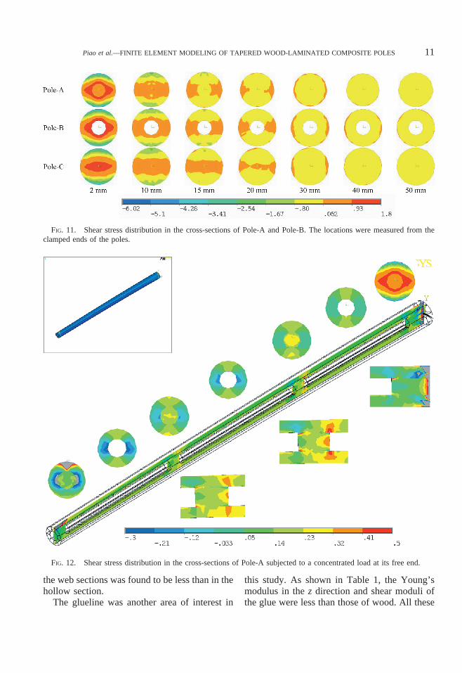
the web sections was found to be less than in thehollow section.
The glueline was another area of interest in
this study. As shown in Table 1, the Young’smodulus in the z direction and shear moduli ofthe glue were less than those of wood. All these
FIG. 11. Shear stress distribution in the cross-sections of Pole-A and Pole-B. The locations were measured from theclamped ends of the poles.
FIG. 12. Shear stress distribution in the cross-sections of Pole-A subjected to a concentrated load at its free end.
Piao et al.—FINITE ELEMENT MODELING OF TAPERED WOOD-LAMINATED COMPOSITE POLES 11
Fig. 11 live 4/C Fig. 12 live 4/C

suggested gluelines were the weak sections ofthe composite poles. Their effects on normal andshear stress distributions can be seen in Figs. 7,12, and 13. The previous results from the test ofPole-B showed that the pole failed at shear ini-tiated by a bonding defect at the top (Piao et al.2006). The failure occurred in the gluelines thatwere subjected to the greatest shear as shown bythe No. 6 cross-section in Fig. 13. Processingerrors of wood strips, insufficient pressing pres-sure, and lack of glue in the gluelines may alllead to bonding defects or weak gluelines, whichreduced the strength of the poles and should beavoided.
CONCLUSIONS
Five finite element models with ANSYS havebeen developed and verified with the experiment
results. The predicted deflection by these modelsagreed well with those of the experiment, andthe predicted normal stress agreed with thosecalculated. The normal and shear stress distribu-tions inside the members were investigated, andstress distributions in XY and YZ planes wereexhibited. As expected, the node-like webs re-duced the local shear stress and improved theshear capacity, especially on the pole top and inclamped line regions where shear levels were thehighest, but had little effect on the bendingstress. The shear stress increased from the bot-tom to the top for the members with taper. Largeshear stress concentration was predicted in asmall region around the clamped lines. Themodels also predicted that the shear stress of thetapered hollow poles decreased from the insideto the outside surfaces in a cross-section in the
FIG. 13. Shear stress distribution in the cross-sections of Pole-B subjected to a concentrated load at its free end.
WOOD AND FIBER SCIENCE, JANUARY 2008, V. 40(1)12
Fig. 13 live 4/C

XY plane. Gluelines were the weak regions thatwere likely subjected to shear failure.
Taper, node-like webs, shell wall thickness,and gluelines were investigated in this study.However, their effects on the performance ofcomposite poles are mostly still unknown andwill be investigated in the next study.
REFERENCES
ADAMS, R. D., G. P. KRUEGER, S. LONG, A. E. LUND, AND
D. D. NICHOLAS. 1981. Compole™—The compositewood material utility pole. Proc. Am. Wood ProtectionAssoc. Pp. 1–6.
AMERICAN WOOD PRESERVERS INSTITUTE (AWPI). 1996.Wood Preserving Industry Production Statistical Report.2750 Prosperity Avenue, Suite 550, Fairfax, VA.
BIOMIMICRY. 2006. http://www.biomimicry.net/intro.htmlBRATKOVICH, S. M. 2002. Markets for recycled treated wood
products. Pages 37–40 in Proc. Enhancing the Durabilityof Lumber and Engineered Wood Products. Forest Prod.Soc. Madison, WI.
ERICKSON, R. W. 1994. The hollowed veneered pole. Pages465–468 in J. Wells, ed. Proc. Pacific Timber Engineer-ing Conference. Queensland University of Technology,Brisbane, Australia.
———. 1995. Hollow veneered pole. U.S. Patent No.5,438,812. 1990. Mechanics of materials. 3rd ed. PWS-KENT Publishing Company, Boston, MA. 807 pp.
GERE, J. M., AND S. P. TIMOSHENKO. 1990. Mechanics of
materials. 3rd ed. PWS-KENT Publ. Co., Boston, MA.807 pp.
HOCKADAY, E. 1975. What does structural glue laminatedwood have to offer the electrical utility industry. in Proc.6th Wood Pole Institute. Colorado State Univ., Ft. Col-lins, CO.
MCKAIN, B. 1975. Laminated wood for utilities—A combi-nation of versatility, economics and beauty. Proc. 6th
Wood Pole Institute, Colorado State University, Ft. Col-lins, CO.
MARZOUK, H. M., M. U. HOSEIN, AND V. V. NEIS. 1978.Built-up utility poles using prairie timber. Forest Prod. J.28(11):49–54.
PIAO, C., T. F. SHUPE, AND C. Y. HSE. 2004. Mechanicalproperties of small-scale wood-laminated compositepoles. Wood Fiber Sci. 36(4):536–546.
———, ———, R. C. TANG, AND C. Y. HSE. 2005. Finiteelement analyses of wood-laminated composite poles.Wood Fiber Sci. 37(3):535–541.
———, ———, ———, AND ———. 2006. Mechanicalproperties of small-scale laminated wood compositepoles: Effects of taper and webs. Wood Fiber Sci. 38(4):633–643.
SHIDLES, J. B. SC. 1970. Adhesive Handbook. CRC Press, ADivision of the Chemical Rubber Co., Cleveland, OH.
TANG, R. C., AND S. F. ADAMS. 1973. Application of rein-forced plastics for laminated transmission poles. ForestProd. J. 23(10):42–46.
USDA FOREST PRODUCTS LABORATORY (USDA FPL). 1999.Wood handbook-Wood as an engineering material. Gen.Tech. Rep. FPL-GTR-113. USDA Forest Service, ForestProd. Lab., Madison, WI. 463 pp.
Piao et al.—FINITE ELEMENT MODELING OF TAPERED WOOD-LAMINATED COMPOSITE POLES 13