Embed Size (px)
Citation preview

International Journal of Science and Research (IJSR) ISSN (Online): 2319-7064
Impact Factor (2012): 3.358
Volume 3 Issue 7, July 2014 www.ijsr.net
Licensed Under Creative Commons Attribution CC BY
Finite Element Analysis of Springback of a Sheet Metal in Wipe Bending Process
Amul Biradar1, M.D Deshpande2
1Departament of Mechanical Engineering, KLS’s Gogte institute of technology,
VTU Belgaum, Karnataka, India
2Professor, Department of Mechanical Engineering, KLS’s Gogte institute of technology, VTU Belgaum, Karnataka, India
Abstract: This work presents a study of spring back in wipe bending metal forming process. Spring back is one of the most sensitive features of the sheet metal forming, which occurs due to elastic recovery during unloading. The main purpose of this work is spring back prediction of sheet metal copper alloy and investigation into the causes of the spring back, such as process parameter, geometry of tools etc. In this work the prediction model of spring back in wipe bending process was developed using finite element method code ANSYS APDL 14.0 and an over bend approach is applied to compensate the spring back and the obtained spring back for different process parameters are validated by analytical method. Keywords: Springback, Plasticity, Wipe bending, over bend approach. 1. Introduction A large variety of metallic parts of automobiles, aircrafts, building products and domestic appliances are produced by deformation processing. This comprises manufacturing methods that are used to create the primary shape of products by plastically deforming the material. Well-known examples are forging, rolling, extrusion, sheet metal forming and hydro forming. Sheet metal forming is a special class of deformation processes in which blanks, with the thickness being much smaller than the other dimensions, are formed into the desired shape. [9] Sheet metal forming is one of the most widely used manufacturing processes for the fabrication of a wide range of products in many industries. The reason behind sheet metal forming gaining a lot of attention in modern technology is due to the ease with which metal may be formed into useful shapes by plastic deformation processes in which the volume and mass of the metal are conserved and metal is displaced from one location to another. [7] Sheet metal forming operations consists of simple bending, ironing, wheeling, press brake forming, stretch forming, roll forming, rubber-pad forming, stamping, flanging, spinning, embossing, bulging, hyper plastic forming, peen forming, explosive forming, magnetic-pulse forming and deep drawing of complex parts [6] Indeed, the sheet metal products have become current also due to low price, accuracy of dimensions, durability and favorable physical properties. In today’s industry, where the costs play a very important role, the sheet metal products have replaced many products made by forming process. They have replaced also many complex composed products. [7] In every industry, quality and productivity are major issues for being competitive. For example, a car frame needs to be
designed to achieve strength requirements and aesthetic aspects; on the other hand, cost of production and repeatability is crucial to the business. A stamping process has been one solution used in practice to achieve these goals in the sheet metal fabrication business. However, springback, a shape discrepancy between the fully loaded and unloaded configurations, undermines the stamping benefits, since a major effort on the tooling design is needed to compensate springback. In many industries, e.g. automotive industries, springback plays an important role in tooling and process designs. To effectively predict springback for potential application in determining optimal tooling shapes and process parameters, understanding the mechanics of springback, a mainly elastic recovery process, is essential. [14] In the bending technology it is difficult to achieve accurate and repeatable angle of a bend. This problem is caused by elastic springback, which is considerable in processes of sheet metal forming [1-4]. Springback in processes of sheet metal forming causes troubles in assembling processes, because springback entails anomaly of required shape of the part. Economical aspect of problems associated with springback is in the USA solely in the sphere of automotive industry estimated on the 50 million dollar per year [5]. Springback is defined as a dimensional change of a shape after releasing a tool due to elastic effects [6]. In the past, handy tables or graphs were the traditional ways used for prediction of springback. For this purpose, today are frequently used FE codes, which provide numerical simulations of sheet metal forming processes. [2]
Paper ID: 07071415 852

International Journal of Science and Research (IJSR) ISSN (Online): 2319-7064
Impact Factor (2012): 3.358
Volume 3 Issue 7, July 2014 www.ijsr.net
Licensed Under Creative Commons Attribution CC BY
2. Principle of Springback and Wipe bending process The elastic strains remaining in the bend region after bending load or pressure is removed will leads to a slight decrease in the bend angle. This decrease in bend angle is known as spring back, as shown in below figure. The springback phenomenon will vary according to the material type, thickness and hardness. A larger bend radius will also cause grater spring back. For forming process the material will be stressed beyond elastic limit so that the permanent deformation takes place. The material status enters the plastic deformation region. Hence the sheet metal can be formed. Figure shows the principle of spring back. [14]
Figure 1: principle of springback
A wiping die is as shown in fig. Here the work piece is clamped to a die block by a spring-loaded or fluid-cylinder pressure pad, and the punch wipes the extended materials over one edge of the die. A bend radius is provided on the edge of the die block. A radius or chamfer is often provided on the leading edge of the punch to prevent the wiping action from being too severe. [11]
Figure 2: Wipe bending process 3. Experiments to study springback in metals Many experimental methods are developed to study and understand the springback phenomenon. The most common and standard methods are air bending, wipe bending, V bending, U bending and cylindrical bending as shown in below figures. These are the rottenly used techniques to study the difficulties and causes associated with springback phenomenon.
Figure 3: Cylindrical, U and V bending
The sensitive basic parameters which are influencing springback such as tool radius die radius, sheet thickness and other geometrical parameters are studied practically by means of these methods. The major disadvantage of these experimental methods is that they cannot follow the realistic process conditions that take place during sheet metal forming. Stretch bending is one of the bending tests that are carried out to determine the importance of tension in compensating the springback. [15] 4. Plasticity Most of regular materials in engineering applications results a linear stress-strain response up to a stress level known as the proportional limit. Further this limit, the stress-strain response will become nonlinear, but will not inelastic. And plastic behavior of the material is said to be non-recoverable strain, which start to begin when applied load or stress exceed the material’s yield point. Plasticity theory was developed to investigate or predict the characteristics of metals under loads above the elastic limit. Plasticity phenomenon is a non-conservative, path dependent phenomenon. In other words, the series in which the loads are applied and resulting plastic response of the material affects the final results. If plastic reaction is introduced in the analysis, loads applied in a sequence of small increments load step which will follow the load –reaction path as closely as possible. Along with the plasticity other types of nonlinear behavior might also occur. Specifically like geometric nonlinearities with plastic material reaction which is taken care during the FE analysis, material stress-strain properties may also be used for large deformation analysis. [13] Important points in modeling the metal plasticity: 1. The division of strain into elastic strain and plastic strain 2. Yielding criterion which describes the behavior of the
solid model which predicts the elasticity and plasticity response of the material.
3. By controlling the shape of the stress-strain curve by using strain hardening rules.
5. Wipe-Bending Process and FE Simulation The wipe-bending process is one of the widely applied bending operations for flanging. In this study, the bending process was simulated using finite element (FE) software ANSYS (14.0).
Paper ID: 07071415 853
International Journal of Science and Research (IJSR) ISSN (Online): 2319-7064
Impact Factor (2012): 3.358
Volume 3 Issue 7, July 2014 www.ijsr.net
Licensed Under Creative Commons Attribution CC BY
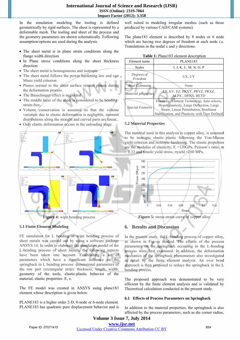
In the simulation modeling the tooling is defined geometrically by rigid surfaces. The sheet is represented by a deformable mesh. The tooling and sheet of the process and the geometry parameters are shown schematically. Following assumption/options are used during the analysis. The sheet metal is in plane strain conditions along the
flange width direction In Plane stress conditions along the sheet thickness
direction The sheet metal is homogeneous and isotropic The sheet metal follows the power hardening law and von
Mises yield criterion Planes normal to the sheet surface remain planes during
the deformation process The Bauschinger effect is neglected The middle layer of the sheet is considered to be bending-
strain-free, Volume conservation is assumed so that the volume
variation due to elastic deformation is negligible, moment distributions along the straight and curved parts are linear,
Only elastic deformation occurs in the unloading stage.
Figure 4: wipe bending process
5.1 Finite Element Modeling FE simulation for L bending or wipe bending process of sheet metals was carried out by using a software package ANSYS 14. In order to elaborate the simulation model of the L-bending process of sheet metals, the following aspects have been taken into account. Establishing a set of parameters which have a significant influence on the springback in L bending process: dimensional parameters of the raw part (rectangular strip): thickness, length, width; geometry of the tools, elastic-plastic behavior of the material, elastic properties: E, υ. The FE model was created in ANSYS using plane183 element whose description is given below. PLANE183 is a higher order 2-D, 8-node or 6-node element. PLANE183 has quadratic pure displacement behavior and is
well suited to modeling irregular meshes (such as those produced by various CAD/CAM systems). The plane183 element is described by 8 nodes or 6 node which are having two degrees of freedom at each node i.e. Translations in the nodal x and y directions.
Table 1: Plane183 element description Element name PLANE183
Nodes I, J, K, L, M, N, O, P
Degrees of Freedom
UX, UY
Real Constants None
Material propertiesEX, EY, EZ, PRXY, PRYZ, PRXZ,
ALPX , DENS, BETD
Special Features
Elasticity, Element Technology Auto selects, Hyper elasticity, Large Deflection, Large
Strain, Linear Perturbation, Nonlinear Stabilization, and Plasticity with User Defined
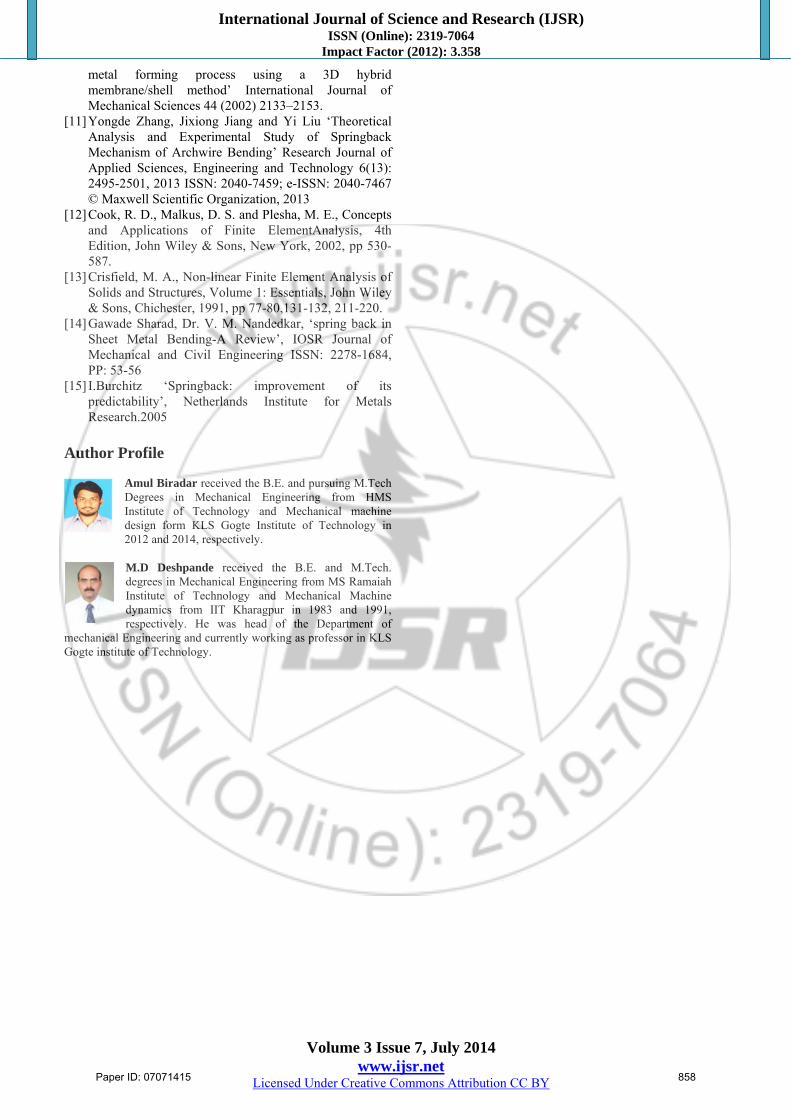
5.2 Material Properties The material used in this analysis is copper alloy, is assumed to be isotropic elastic–plastic following the Von-Misses yield criterion and isotropic hardening. The elastic properties are the modulus of elasticity, E =120GPa, Poisson’s ratio, m = 0.33 and tensile yield stress, σyield =260 MPa.
Figure 5: stress-strain curve of copper alloy
6. Results and Discussion In the present study, the L-bending process of copper alloy, as shown in Fig. is studied. The effects of the process parameters on the springback occurring in the L-bending process were first examined. In addition, the deformation mechanics of the springback phenomenon also investigated in detail by the finite element analysis. An over bend approach is then proposed to reduce the springback in the L bending process. The proposed approach was demonstrated to be very efficient by the finite element analysis and is validated by Theoretical calculation conducted in the present study. 6.1 Effects of Process Parameters on Springback In addition to the material properties, the springback is also affected by the process parameters, such as die corner radius,
Paper ID: 07071415 854

International Journal of Science and Research (IJSR) ISSN (Online): 2319-7064
Impact Factor (2012): 3.358
Volume 3 Issue 7, July 2014 www.ijsr.net
Licensed Under Creative Commons Attribution CC BY
punch radius, blank-holder force, and friction condition in the L-bending process. In order to determine the predominant ones among these process parameters, the finite element analysis was performed using the Copper alloy sheet as specimen. One process parameter was examined at a time, while the other process parameters were remained the same. The effect of the die corner radius on the springback has been discussed and shown in fig-6. The effect of punch radius on the springback is shown in fig-7. It is observed in Fig that the springback increases as the punch radius increases for the punch radii smaller than 1.2 mm, and then the springback decreases as the punch radius further increases. It implies that there is an optimum punch radius in the L-bending process to reduce the springback. However, the optimum punch radius is quite small and the effect of the punch radius on springback is not so obvious, hence, it is not practical to reduce the springback by changing the punch radius. Fig-8, shows the effect of die gap on the springback. As seen in Figure, the die gap has a significant effect on springback, and the larger the die gap, the more significant is the springback. Since the sheet-metal is less constrained around the die corner when the die gap becomes large, resulting in larger positive springback. 6.2 The Effect of Die Radius In order to investigate the effect of die radius on the springback angle of the L bend or wipe bending process, the following strategy is employed. Five groups of FE simulation models each with the different die radius varying from 0.2 to 1.4 mm and for each trails other parameters are taken constant, i.e. sheet thickness is 0.3 mm, Punch radius is 0.2 mm and die gap of 0.3 mm.
Table 2: Effect of die radius on springback Die radius (mm) Springback in deg. (Ɵ)
0.2 1.59 0.5 1.71 0.8 2.4 1.1 2.55 1.4 2.81
The FE simulation response of springback angle for the die shoulder radius is reported in Table 1. And also using these results from simulation, the graph of springback angle against die radius is plotted, as shown in Fig.10.
Figure 6: Effect of die radius on springback
6.3 The Effect of Punch Radius In order to investigate the effect of punch radius on the springback angle of wipe bending process, the following strategy is employed. Five groups of FE simulation models each with the different Punch radius varying from 0.2 to 2 mm and for each trails other parameters are taken constant, i.e. sheet thickness is 0.3 mm, die gap of 0.3 mm and die radius can be taken in between 0.2 to 0.5 mm because from the earlier analysis for different die shoulder radius, the elastic strain induced was minimum and plastic strain was maximum in tensile direction and reported less springback.
Table 3: Effect of punch radius on springback Punch radius (mm) Springback (Ɵ)
0.2 1.71 0.4 2.35 0.6 2.37 0.8 2.57 1 2.6
1.5 2.35 2 2.2
0
1
2
3
0.2 0.7 1.2 1.7 2.2
SPRINGBACK (D
eg)
PUNCH RADIUS (mm)
Figure 7: Effect of punch radius on springback
6.4 The Effect of Die Gap and Sheet Metal Thickness In order to investigate the effect of die gap and sheet metal thickness on the springback the same strategy is used as earlier i.e. five different FE modules are prepared for different die gaps varying from 0.3 to 1 mm and thickness varying from 0.3 to 1 mm. In the die gap trails the gap is provided equal to the thickness in order to avoid the reduction in the sheet metal thickness. And the results for both are reported under following tables.
Table 4: Effect of Die gap on springback Die gap or clearance (mm) Springback (Ɵ)
0.3 2.52 0.4 4.51 0.5 6.54 0.6 7.29 0.7 8.45
Paper ID: 07071415 855

International Journal of Science and Research (IJSR) ISSN (Online): 2319-7064
Impact Factor (2012): 3.358
Volume 3 Issue 7, July 2014 www.ijsr.net
Licensed Under Creative Commons Attribution CC BY
0246810
0.3 0.5 0.7 0.9
SP
RIN
GB
AC
K
(Deg
)
DIE GAP (mm)
Figure 8: Effect of die gap on springback
Table 5: Effect of sheet thickness on springback Thickness (mm) Springback (Ɵ)
0.3 2.35 0.4 2.01 0.5 1.72 0.6 1.69 0.7 1.5
0
1
2
3
0.3 0.4 0.5 0.6 0.7 0.8
SPRINGBACK
(Deg)
THICKNESS (mm)
Figure 9: Effect of sheet thickness on springback
7. Over Bend Approach One of the common techniques used for compensating the springback is over bending the sheet metal with more angles then required. To apply this method, the amount of springback is calculated and the sheet metal is over bent to a smaller bend angle than required. Recovery of the sheet metal from the springback results in a calculated increase in bend angle. This increase due to the elastic strains makes the recovered bend angle exactly what was originally planned. For a case of 0.8mm die radius, for which we know the springback angle, which is used to show the effect of over bend for eliminating the springback i.e. to get the required 90° angle required for this work. But this solution is obtained by trial and error method as solved for a case shown below. And after analyses of springback compensation with an over bend method for a sample of 90° we can say that it is an effective and simple method to obtain the required angle of bend.
Table 6: Die undercut in deg. to minimize the springback Die undercut in deg. Springback (Ɵ)
2.4 -0.58 2 -0.5
1.5 -0.28 1 0.04 (optimum)
a) Over bend
b) Reauired 90 deg. Bend
Figure 10: an over bend approach
8. Analytical method To validate the FE analysis a theoretical approach is applied. Strain at the outer fiber = (change in length / original length)
(1)
Change in length =
Original length = Where, Ro = sheet metal bend radius (outer) Rn = radius of neutral fiber or mean radius Ri =sheet metal bend radius (inner)
Mean radius (Rn) =
= Rn= 0.65mm Now from equation (1)
Total strain at the outer fiber = Ԑt=0.23 Now from the stress-strain curve for total strain of 0.23, the elastic strain reversible strain measured was of about 0.0045 and the remaining strain is plastic strain or irreversible strain.
Paper ID: 07071415 856

International Journal of Science and Research (IJSR) ISSN (Online): 2319-7064
Impact Factor (2012): 3.358
Volume 3 Issue 7, July 2014 www.ijsr.net
Licensed Under Creative Commons Attribution CC BY
Figure 10: Showing Elastic strain from Stress-Strain curve
Ԑt=Ԑe+Ԑp (2)
(3) Where, T=sheet metal thickness
δelastic = (Ԑelastic)*(length of bent region) (4) δelastic = change in length due to Elastic strain
Now from equation (3)
Radians
9. Conclusion From the investigation of Finite element analysis it shows that the die radius has a significant amount of effect on the springback. The results from analysis for die shoulder shown that the increase in die shoulder radius increases the springback hence to avoid the springback use of smaller die radius is recommended from this study. And also the punch nose radius has significant effect on the springback, up to certain punch nose radius though it doesn’t have much effect as compared to the die radius on springback. Apart from these two factors the die gap or clearance and sheet metal thickness also has a very appreciating amount of effect on springback, from this analysis it shown that an sufficient amount of die gap has to be maintained (same as thickness of the sheet metal) in order to compensate the springback and also to avoid some of the defects such as tearing. Closer or less clearance may lead to damaging which results in waste of material and cost. Springback is also affected by the thickness; however this parameter depends on the requirement for manufacturing. An over bend approach is proposed to compensate the springback. After analyzing the different parameters responsible for the cause of springback, the springback is controlled for some extent but cannot be eliminated. Hence the over bend approach based on trial and error is chosen in
this work by which the springback is almost eliminated. And for validation of this FE analysis a suitable theoretical computation is done. This shows good agreement with the results from analysis. 10. Scope of Future Work The method of Finite element analysis by ANSYS can also be extended to other materials with different mechanical properties. Behaviors of springback of different materials can be studied further and compared. For more accurate measurement of springback Bauschinger effect can be considered. In industries there is lot of requirement for the solutions to the cause of springback hence in further studies different solution techniques can be developed. In this current work isotropic hardening law was considered for the material model, to predict the springback more accurately future ANALYSIS can be carried out by modeling the models with different hardening laws such as Kinematic hardening law, which also considers the Bauschinger effect. References [1] Abdulaziz alghtani, P.C. Brooks, D.C. Barton, V.V.
Toropov ‘springback analysis and optimization in sheet metal forming’ 9th European LS-DYNA conference 2013.
[2] Jan slota, Miroslav jurcisin ‘experimental and numerical prediction of springback in v-bending of anisotropic sheet metals for automotive industry’zeszyty naukowe politechniki rzeszowskiej, Mechanika z. 84 (3/12) 2012.
[3] Recep Kazan, Mehmet Fırat, Aysun Egrisogut Tiryaki ‘Prediction of springback in wipe-bending process of sheet metal using neural network’ Materials and Design 30 (2009) 418-423.
[4] Fuh-Kuo Chen, Shen-Fu Ko ‘Deformation analysis of springback in L-bending of sheet metal’ journal of achievements in materials and manufacturing engineering volume 18, issue 1-2, 2006.
[5] Z. Marciniak, J.L. Duncan, S.J. Hu ‘Mechanics of Sheet Metal Forming’ First published by Edward Arnold, London, 1992 Second edition published by Butterworth-Heinemann 2002 Copyright � 2002 S.J. Hu, Z. Marciniak, J.L. Duncan All rights reserved.
[6] Florica mioara groze; gheorghe achimas lucian lazarescu , vasile adrian ceclan ‘ springback prediction of the v bending process using finite element simulation’ 7th international multidisciplinary conference baia mare, romania, may 17-18, 2007 issn-1224-3264.
[7] Ivan sachy ‘Handbook of die design second edition’ Copyright © 2006, 1998 by Ivana Suchy., McGraw-Hill
[8] Filip Lindberg ‘Sheet Metal Forming Simulations with FEM’ Master’s Thesis in Engineering Physics, 30 ECTS jan 2011.
[9] I.A. Burchitz ‘improvement of springback prediction in sheet metal forming’ ISBN 978-90-365-2656-2. Copyright 2008
[10] Jeong-Whan Yoona, Farhang Pourboghrat, Kwansoo Chung, Dong-Yol Yang Springback prediction for sheet
Paper ID: 07071415 857
International Journal of Science and Research (IJSR) ISSN (Online): 2319-7064
Impact Factor (2012): 3.358
Volume 3 Issue 7, July 2014 www.ijsr.net
Licensed Under Creative Commons Attribution CC BY
metal forming process using a 3D hybrid membrane/shell method’ International Journal of Mechanical Sciences 44 (2002) 2133–2153.
[11] Yongde Zhang, Jixiong Jiang and Yi Liu ‘Theoretical Analysis and Experimental Study of Springback Mechanism of Archwire Bending’ Research Journal of Applied Sciences, Engineering and Technology 6(13): 2495-2501, 2013 ISSN: 2040-7459; e-ISSN: 2040-7467 © Maxwell Scientific Organization, 2013
[12] Cook, R. D., Malkus, D. S. and Plesha, M. E., Concepts and Applications of Finite ElementAnalysis, 4th Edition, John Wiley & Sons, New York, 2002, pp 530-587.
[13] Crisfield, M. A., Non-linear Finite Element Analysis of Solids and Structures, Volume 1: Essentials, John Wiley & Sons, Chichester, 1991, pp 77-80,131-132, 211-220.
[14] Gawade Sharad, Dr. V. M. Nandedkar, ‘spring back in Sheet Metal Bending-A Review’, IOSR Journal of Mechanical and Civil Engineering ISSN: 2278-1684, PP: 53-56
[15] I.Burchitz ‘Springback: improvement of its predictability’, Netherlands Institute for Metals Research.2005
Author Profile
Amul Biradar received the B.E. and pursuing M.Tech Degrees in Mechanical Engineering from HMS Institute of Technology and Mechanical machine design form KLS Gogte Institute of Technology in 2012 and 2014, respectively.
M.D Deshpande received the B.E. and M.Tech. degrees in Mechanical Engineering from MS Ramaiah Institute of Technology and Mechanical Machine dynamics from IIT Kharagpur in 1983 and 1991, respectively. He was head of the Department of
mechanical Engineering and currently working as professor in KLS Gogte institute of Technology.
Paper ID: 07071415 858