Embed Size (px)
Citation preview

pqpmn^nmwwmnu. up,. mm «IP'iinr iJ " ■ im- "'■■—■ "!«!.■ ■■■■■'» i ■■>!■» :«.IIWI I-JVI ■■■■■■■ ILH4I. yn^iiii* „iraw
00 (\>
o
i TECHNICAL REPORT
76-21 -AMEL
FINITE-ELEMENT ANALYSIS OF
SCALE-MODEL FRAME-SUPPORTED TENTS
D D C
ÄUG »3 1976
n
u
Approved for public release;
distribution unlimited.
MARCH 197a
UNITED STATES ARMY •NATO RESEARGH and DEVELOPMENT COMMAND
* :?: NMICK, MÄSSACHUSiTTS 01 ?$£*
ENGINEERING SCIENCES DIVISION AERO-MECHANICAL ENGINEERING LAB
^)^■t^llWl^f«^llm1■^1llH■l^l^fl^«ii^^'"-'^;•■'tea^"i"^'* tmffliiM4ilffi«Mi

Approved for public release, distribution unlimited.
Citation of trade names in this report does not constitute an official indorsement or approval of the use of such items.
Destroy this reporc when no longer needed. Do not return it to the criginstor.
■■ m
S?fift'Jk"tf-iiiiitn'- ,
"'minimal m

* ' .^-:vr — ■ upMTWyL tmi» ■■■'■■■■ J' P!M»J«P«
Ä'-"; ■
UNCLASSIFIEP Ü6jmRAJ)cdM
SECURITY Cl, ASSIFICATION OF THIS PA01 (1WI«B Dim tollend)
REPORT DOCUMENTATION PAGE anHTEsin:
76-21-AMEL
ll. OOVT ACCIMION NO.
«^ TITLE (end mMam) _
JNNITE-jELEMENTjJkNALYSIS OF SCALE-MODEL J[RAME-|UPPORTED JENTS.
■ AUTMoy.i _ 1 "«j i. LUHiHMll UP.UP.MI HUUJLi«,
Paul J/*emington, John C.AD'Callahan RicharoWladden //* n 1 '. '- 1 ' {/O /fOAAKp3-74-C-0\93j^ '°
S. PERFORMING ORGANIZATION NAME AND ADDRESS
Bolt Beranek and Newman, Inc. GO Moulton St. Cambridge, MA 02138
CONTROLLING OFFICE NAME ANO ADDRESS
Aero-Mechanical Engineering Laboratory (AMEL) Engineering Sciences Division (ESD) US Army Natick Res. & Dev. Command, (NARADCOM)
ffl.
14. MONITORING AGENCY NAME A AOORESSf" dlllerent «ran Controlling Olllce)
N/A M&rA l IT IS. DISTRIBUTION STATEMENT (öl Oil» Report)
READ INSTRUCTIONS BEFORE COMPLETWO FORM
s. RECIPIENT'S CATALOO NUMBER
OF REPORT A PERIOCCOVEREO
10. PROGRAM CLEMENT. PROJECT. TASK AREA • WORK UNIT NUMBERS
Technical Efforts 1T762713DJ40 Task 36 Work Unit 020
Hi ■rmiTiuT» Marc«|75 I
I). NUMIIR OF PAGES
55 IS. SECURITY CLASS, (ol this report)
Unclassified
IS«. DECLASSIFICATION/DOWNGRADINO SCHEDULE
Apptoyed for public release - distribution unlimited.
17. DISTRIBUTION STATEMENT (at Ihm mbetrecl entered In Block 20, II dlllerent from Report)
Same
m l-f-762 ^/?-DT-V*5i IS. SUPPLEMENTARY NOTES
To be distributed by the (NTIS) National Technical Information Service, US Department of Commerce, 5285 Port Royal Road, Springfield, VA 22151
9. KEY WORDS (Continue on reverie »Id» II necemmery and Identity by block number)
Tents Tentage Framed Structures Measurements
Analysis Models Stresses Full-scale Shelters Deflection Trusses Shelters Beams (Joint Efficiency)
Guylines Tests Loads (Static) Computer Programming
20. ASBTRACT (Continue on reveree aid» II neceeemry end Identify by block number)
Frame supported tents are used extensively in field army operations because of their light weight, easily transportable and easily erected. However, until recently, no analysis existed of the behavior or frame-supported tents under static loads such as snow. The Army initiated a program in which a computer code was developed to predict the stresses and deflections in typical segments of frame-supported tents under static loads. This report describes a continuation of the initial study that focuses primarily on extending the capabilities of the original computer code.
00 ,' FORM
AN 73 1473 EDITION OF I NOV 0* IS OBSOLETE UNCLASSIFIED
SECURITY CLASSIFICATION OF TMIS PAGE (When Dim Bntered)
Ofo J loo W"
ti... "vwffiwaw
SMBHMH -.■.... - - a

—,. . I . (.11
UNCLASSIFIED MC-JWtf CLASSIFICATION OP TMI» PA9t(Wtm
20. ABSTRACT (cont'd)
The capability of the finite-elemenucomputer coda praaantad in, 'Analysis of itraaMi and Deflections In Frame Supported Tents (US Army Natlck Laboratories TR 76-31) has bean expanded to Include more representative models of full-scale shelters. Routines have bean developed to ease the inputing of initial fabric shape end yarn orientation, and three new finite elements — a truss, a guyline and a baam with joint efficiency — have been added to the code element library. In a companion experimental program, deflections of fabric stresses and frame stresses on two 1/8-scale-model tents have been found to agree well with computer code predictions. A new element has been developed that allows for slipping of the fabric over frame elements, and preliminary testing has shown that its predictions agree well with laboratory measurements.
«crows*
im tee BUMtsssn jantfiMTMa.
«mm sect!« siniMtiH a
a
V
Mnmmss/tfajMun asm
m gs m/»-s?asr
UNCLASSIFIED SECURITY CLASSIFICATION OF THIS PAGEfHTun Data Enftmd)
. . l.~> .::.^..r~..> ■.,.,. rVr, i^-i-Ld Tyr r ;iTtt?TSfcttfih<iiyfttt'irVi i rvi! nL

lU.J .»,JmW^IUI4»!*»»'Jf pV^ttUHPppV' ■ . . »J.JU.[:.-..",'II>-.»„ :! M<, .IIWWIPB!1"; i-r,HLIILWTCPqHpfP
■ .-■ t_ .* ■ . *. ■. • •- - ■
PREFACE
i\ I-
This report was prepared by Bolt Beranek and Newman, Inc. under U.S. Army Contract DAAK03-74-C0193. The work was carried out under the direction of project managen Dr. Constantin J. Monego and Or. Earl C. Steeves of the U.S. Army Natick Research and Development Command (MARADCOM). NARADCOM has also been known as the "US Army Natick Laboratories" (NLABS) and "US Army Natick Development Center (NDC).
■ 'j
f! W
-
I
m
jaÜliKüi...

i'.Ji*,JW|»^-!^Er .WH>: ^■(IJIJJJILl Jl'^Jt-« -:„-■■- ' ■ ■—'
,v . ,tr «umWiqißju
I
TABLE OF CONTENTS
LIST OF FIGURES
1. INTRODUCTION
2. BEAM ELEMENT WITH JOINT EFFICIENCIES
2.1 Element Description
2.2 Joint Efficiency Laboratory Tests
3. SCALE-MODEL TENT TESTS
3.1 Computer Descriptive, of the Tent Models
3.2 Laboratory Instrumentation
3.3 Comparison of Computer Predictions and Measurements on the Scale-Model Tents
4. FABRIC SLIPPAGE
4.1 Strip Finite Element with Slippage Capability
4.2 Experimental Verification of the Fabric Slippage Element
4.2.1 Friction at the fabric-frame interface
4.2.2 Laboratory test of the 1-D string element
5. RECOMMENDATIONS FOR FURTHER WORK
Pago
4
7
8
8
11
19
19
26
25
42
42
46
46
49
51
^***^*

1 " '""*""ww*m^mr—^mm . ■ ■ n i * l^
1
1 Figur«
- 2.1 [ i 1 1
2.2
2.3 ■
i 2.4 j i C
j 2.5
2.6
f 2.7
2.8
4
3.1
3.2
3.3
; 3.4
- 3.5 ;
3.6
3.7
1- 3.8
t r 3.9
J. 3.10
LIST OF FIGURES
Paga
Beam Element With Joint Efficiency Capability 9
Typical Model Tent Frame Joints 12
Apparatus for the Measurement of Joint Efficiencies 14
Slant-Roof Frame Joint Efficiencies 16
Arch-Roof Frame Joint Efficiency 17
Clearance Hole Joint Efficiency Measurement 18
Clearance Hole Joint Efficiency for the Slant-Roof Frame 20
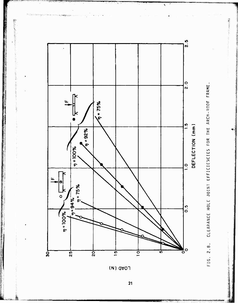
Clearance Hole Joint Efficiencies for the Arch-Roof Frame 21
Slant-Roof Tent Computer Model 22
Arch-Roof Frame Computer Modei 23
Fabric Stress Gauge 27
Slant-Roof Tent Fabric Stresses Parallel to the Arches 28
Slant-Roof Tent Beam Stresses, Node 9 29
Slant-Roof Tent Beam Stresses, Node 17 30
Slant-Roof Tent Beam Stresses, Node 5 31
Comparison of Measured and Predicted Deflections in the Slant-Roof Tent at Node 11 32
Z Deflection in the Slant-Roof Tent Along Nodes 5-8-11-14-17 Full Load 33
X Deflection in the Slant-Roof Tent Along Nodes 5-8-11-14 Full Load 34
3.11 Arch-Roof Tent Fabric Stress, Arch-to-Arch Direction J5

BBPW.J^p,' . ' ' " ■* " ■ * - ■ ■ I | ip^pWBWPWWWrwiT-irr
'-;.'- ■ ■ ■ --= - -■..:. ■■■■ « ...»
.,,,.. •
]
i
'
-
i
LIST OF FIGURES (cont'd)
Figur«
3.12 Arch-Roof Tent Beam Streuet, Node 11
3.13 Arch-Roof Tent Beam Stresses, Node 27
3.14 Arch-Roof Tent Beam Stresses, Node 27
3.15 Comparison of Measured and Predicted Deflections ir the Arch-Roof Tent at Node 19
3.16 Z Deflection in the Arch-Roof Tent Along Nodes 11-15-19-23-27 With Full Load
3.17 X Deflection in the Arch-Roof Tent Along Nodes 11-15-19-23-27 Full Load
4.1 String Slippage Element
4.2 Fabric/Frame Friction Testing Apparatus
4.3 Ratio of Fabric Stress at Gauge No. 1 to Fabric Stress at Gauge No. 2
4.4 String Slippage Element Test
4.5 Comparison of Predicted and Measured Fabric Strip Deflection and Tension
5.1 Scale-Model Tent Test Configuration
Page i 36
37
38
39
40
41
43
47
48
50
52
55
jihTlrit^aa.a.rf.ifaAi'nV , i ja^a^^^M^^^^"^^—^^M MriMMMMMiM KJp»WPWW<pW IWMflWW

I
FINITE - ELEMENT ANALYSIS OF SCALE-MODEL FRAME-SUPPORTED TENTS
1. INTRODUCTION
One type of shelter used extensively in Army field operations is the frame-supported tent, which is essentially a metal frame with one or more layers of fabric attached to it. This type of shelter has many attractiva features; it is light, easily transported, and easily erected, and it provides a reasonably secure shelter from the weather. However, until recently, nc analysis existed of the behavior of frame-supported tents under static loads such as snow loadings. Although present tent designs are adequate in many ways, such load-response information will assist in the design of future frame-supported tents that will be lighter and more efficient To obtain this load-response information, the Army initiated a program in which a computer code, NONFESA (Nonlinear Finite-Element Structural Analysis) was developed to predict the stresses and deflections in typical segments of frame-supported tents under static loads. As reported by Remington et al' *, the code was verified through comparison of the predictions with measurements on simplified segments of model frame-supported tents.
This report describes a continuation of the NONFESA program that focuses primarily on extending the capabilities of the original finite-element computer code in order to approach more closely the final goal: accurate prediction of the stresses and deflections of both present- and future- generation frame-supported tents. New input subroutines have been developed, and the catalog of elements has been expanded.
Changes in NONFESA include:
The development of truss and guyline elements.
New input subroutines, which ease the input of initial fabric deflection due to slack and allow for arbitrary fabric yarn orientation.
A new beam element wi*h joint efficiencies, to allow for more realistic modeling of frame-element inter-connections.
A new one-dimenaional strip fabric element that allows for slippage over other flexible elements. (This is a first step in dealing with the problem of fabric slippage over frame members in actual tents.)
•'Paul J. Remington, John C. O'Callahan, and Richard Madded (1974). "Analysis of Stresses and Deflections in Frame-Supported Tents," U.S. Army Technical Report No.
75-31, prepared by DAAG17-73-C-0107.
3olt Beranek and Newman Inc. under Contract No.
f*~ mä^^M^^^H&A
tu* IUGS BUMKJW-ygg£.

H
The first two changes - development of truu end guyline elements end new input subroutine* - ere user-oriented modifications. They ere discussed in detail in the User's Manual.1 * The second two changes - cell for more involved revisions of the computer code, end this report concentrates on these changes.
In Section 2, we discuss both the development of the mathematical model for the beam element with joint efficiencies and the companion experimental program, which defined the parameters required by the mathematical model.3** The joint efficiency capabilities of the computer code are the subject of Secfion 3; they are compared with measurements on the scale-model tents. Section 4 presents the development and testing of the fabric strip finite element with slippage capability. Suggestions for future work are presented in Section 5.
2. BEAM ELEMENT WITH JOINT EFFICIENCIES
The computer code presented in Reference 1 had the capability of modeling the interconnection between frama elements as either pinned or rigid. In studies of deflections of *he model tent frames undet load, it was found that this capability had to bt expanded to one dealing with a joint that was somewhere between pinned and rigid. In this section, we describe a beam element that has this capability and outline a number of laboratory tests used to obtain the parameters required for the element in the mathematical model.
2.1 Element Description
The Beam finite element with joint efficiency capability is shown schematically in Figure 2.1. The beam element between Nodes 3 and 4 is identical to that used in Reference 1. This element ?*'!<,*ed for bending deformations (with shear) in two directions, torsional deformations, and extensional deformations. The joint efficiency modifications consist of adding springs between Nodes 1 and 3 anr* 4 and 2. These springs allow for a change in the angle of rotation about the Z- and Y-axes between Nodes 1 and 3 and between Nodes 4 and 2. Any rotation about the X-axis or displacement in the X-, Y-, or Z-directions occurring at Node 1 is measured at Node 3. A similar pattern occures for Nodes 2 and 4.
#2John C. O'Callahan (1974). "NONFESA - A NONIinear Finite Element Structural Analysis Program for the Analysis of Stress and Deflections in Frame-Supported Tents," BBN Report No. 2803. (User's Manual)
**3O.C. Zienkiewicz. The Finite Element Method in Engineering (London, McGraw-Hill, 1971).
m«m»ma0M «ipispHMiii iiss»»>«n*^,«..

,*!,.. fiy^jj^Mm,;jijj.j -, „i~« '•" ' ■■_■'< ■• '«!..»■.! ■-*W!PPW|^^^*WP»
B
f^r^fw ■ i ■■"■•*
♦ Y
T*T ■♦X
FIG. 2.1. BEAM ELEMENT WITH JOINT EFFICIENCY CAPABILITY
i 1
i^li&iiiM^--^^- -, L. -a Vt^^^^^^.ia^^^^^,

-'-..— ■-> . Mr* " —
Mathematically, If we lat tha rotation about tha Z-axli at Noda 1 be $21 and about Noda 3 be «23« tn* banding moment about tha Z-axli applied to tha beam at Node 3 it given by
M23 • K1Z (621 - *Z3*-
where K^ is the rotational spring constant. Similar relationships apply for rotation about the Y-axis at this spring, and about the Y- and Z-axes for the spring connecting Nodes 2 and 4.
I i
Through a procedure «hat is algebraically complicated but conceptually simple, equation'- relating thp displacements and rotations at the 4 nodes to the forces and moments at thest nodes are simplified so that the displacements, rotations, forces, and moments at Nodes 3 and 4 are eliminated; i.e., the degrees of freedom at Nodes 3 and 4 are condensed out The resulting equations relating the forces and moments at Nodes 1 and 2 to the displacements and rotations at those nodes given the element stiffness matrix [K] defined by
"1X
1Y
1Z
M
M
M
1X
1Y
1Z
"2X
"2Y
"2Z
M 2X
M 2Y
M 2Z
- IK]
U
u
1X
1Y
"12
*1X
*1Y
0i
U2X
U2Y
u?z
4>2X
*2Y
10
MBh afiJäteaaaiaEtfi&atiai^ttfct^

, .1 'I. .. •■"*—'- - " " ■ '■ ■ M ■■■' ■ ■ - - ■' ' I ■ | IH
" xHmiHHs#»t>vx' ', . 1 -
>-- I i £
where [K] is a 12 x 12 matrix, F't are nodal force«, M's are nodal moments, U's are modal displacements, 6 is the angle of rotation about the beam axis, and 0's are rotations associated with bending about the Y- and Z-axes. It shouM be noted that only those terms in [K] associated with the bending of the element are affected by the joint efficiency; those associated with torsion or extension of the element remain unchanged. Four new parameters are required for the joint efficiencies in bending in the two orthogonal planes at each end of the beam, TJ^, t?iY' ^22' an(* TJ2Y- These ioint efficincies may take on values from 0 to 1 and are defined by
fii KjjL/2(EI)j
1 + KjjL/2(EI)j
Z,Y
1.2.
where L is the lenyth of the beam element.
2.2 Joint Efficiency Laboratory Tests
In order to use the beam element with joint efficiency ability described above, we require some means of measuring or estimating the effic tncy of a particular joint configuration. In this section, we examine one means of doing this for the joint configuration used in the scale-model tents described in Reference 1.
The existing scale-model tent frames use joints like those shown in Figure 2.2. The slant-roof frame has roundheaded machine screws holding the joints. The arch-roof tent uses a similar joint, except that the joint is held by a flat-head machine screw countersunk in the beam. This type of joint was selected not because it is similar to the type of joints used in real frame-supported tents but because it allows for easy assembly of the frame and easy removal and attachment of the fabric*
For the configurations shown in Figure 2.2, three joint efficiencies are required for each tent frame:
1. bending of beam 1 in and perpendicular to the plane of the three beams about beam 2-3,
2. bending of beam 2 — 3 about the machine screw clearance hole in the plane of the beams, and
'These model tent frame joints are somewhat different from those used in full-scale tent frames. However, capabilities developed in properly modeling these small-scale tent frame joints could be readily extended to full-scale tent frame joints.
11

^mmmmmvm - i ■ ■
SLANT-ROOF ARCH ROOF
O
FIG. 2.2. TYPICAL MODEL TENT ~QAME JOINTS
-
12
■JJ1^i-'TnMM^jji|)y--'l"7'r™"^-^»>---»'-'"'- |||[i] «ÜHJU"*V^*.:«Stf,«^i*--*>'^J*--''?^ W''.. --. -j ,^ . . iai».™;:.«,, i ■■.titmiiiHi^i'.m

will JJI^fl. .J * L, ^ILIWMy^n .M. ), ... j... n, ■ I II .1 ..■ 1^ ,.i -... i, n | ,., ,„,
' '■ '' '■ -
3. bending of beam 2-3 about the machine screw clearance hole perpendicular to the plane of the beams.
We discuss the means for, and the results of, measuring these joint efficiencies on the joints from both tent frames below.
Joint Efficiency (No. 1)
The apparatus for the measurement of the first joint efficiency described above is sketched in Figure 2.3. The crosshatched region shows the fixture for holding the test specimen. The test specimen consists of a long horizontal beam of length L,, attached to two short upright beams of length L2, by means of the bolted joints of Figure 2.2. We now describe how, by applying a point load to the center of the horizontal beam and measuring the deflection, we can derive the joint efficiencies of the bolted joints.
The efficiency of the connection between the upright beams and the holding fixture (simply a bolt pressing the upright beam against a step in the fixture) is not known. However, knowledge of the efficiency of those joints is not needed. If these joints were 100% efficient (i.e., built in), and the bolted joint was also 100% efficient under a point force F, then the deflection at the center of the horizontal beam becomes
6 = FL? 192EI
4- 24L,
L2 + 8L, (2.1)
where E is Young's modulus for the beam material, and I is the moment of inertia of the beams, assuming thai all beams have the same cross section. For L2 « L,, 8 becomes FL|/192EI, which is the deflection one would obtain if the ends of the horizontal beam were built in. If the ends of the vertical beams are simply supported rather than built in, then the deflection becomes
5 = FL?
192EI 4-
24L,
«Li+8L, (2.2)
which for L2 « IM is the same as Eq. 2.1, implying that exact knowledge of the end conditions of the vertical beams is not critical to predicting the center deflection of the horizontal beam. If the bolted joint between the vertical beams and the horizontal beams is 0% efficient (i.e., pinned), the Reflection at the center of the horizontal beam is given by
13
ir^imimvmvmmwmi.. « •

. l.flP-W-Jf- ■ - . ■—I .'.-■ '.* V -i-!|M-M*i-l?MWBJi)Ll»^
FIG. 2.3. APPARATUS FOR THE MEASUREMENT OF .JOINT EFFICIENCIES.
14
X-SO&K:,***^. .-UK. l.-u.iu,, Aiiii'.^.

P'P ■■'■
*'■■■--'-tKr' ^v-
o ■
a factor of 4 larger than the 100% efficient joint This implies that changes in joint efficiency at the bolted joint will create large changes in deflection, making it easy to distinguish differences in the efficiencies of various joints.
Equations 2.1 and 2.2 show that for L, and L7, the upright beams act like rigid walls. We can estima\e the effect of the efficiency of the bolted joints on the center deflection of the horizontal beam under a point load by calculating the deflection of a beam of length L, with torsional springs at each end of the beam attaching it to two rigid walls (see Fig. 2.1). These springs have a stiffness, K, defined as described in Sec. 2.1 The deflection at the center of this beam under a point force, F, is given by
FL? 48EI \
(\ -4 W (2.3)
where is the joint efficiency given by (KL,/2EI)/2EI)/1 + KL/2EI).
With the fixture of Fig. 2.3, two specimens have been tested, one simulating the joints and beams in the slant-roof tent uprights and horizontal beam 6.3-mm x 6.3-mm (0.25-in. x 0.25-in.) with round-headed screws bolting them together, and one simulating the join.s and beams of the arch-roof tent upright beam 8.9-mm x 5.1-mm (0.35-in. x 0.20-in.), horizontal beam 5.1-mm x 5.1-mm (0.20-in. x 0.20-in.), with a flat-head machine screw countersunk in the uprights holding the beams together. The results, shown in Figs. 2.4 and 2.5, are compared with the predictions of Eq. 2.3 for various joint efficiencies. Figure 2.4 shows that as the torque in the bolts holding the beams together in the slant-roof frame joint is increased, the joint efficiency increases to about 72%. Additional torque increases yield no further increase in the joint efficiency. Also shown are the results for the bolts turned down by hand until they felt appropriately tight. Again, the joint efficiency is -72%.
Figure 2.5 shows similar results for the arch-roof frame joints. Those results show that the joint is essentially 100% efficient for reasonable bolt torques (0.22 mN; 2 in./lb).
Joint Efficiency About the Clearance Hole (No. 2 and No. 3)
The apparatus sketched in Figure 2.6 was used to quantify the reduction in beam bending stiffness caused by the clearance holes drilled in the arch members of the model tent frames. Taking straight beams 25.4 cm (~10 in.) long with the same cross section as the arch members of the two model tent frames, we drilled a clearance hole in the center (the arch-roof frame member was also countersunk) to accept the machine screw
15
,:,

_ _^~. .—
-" ■■'"-:*■(*''J*"*-'"'
UJ
-lu. </>0
O
o
X ©
_> O — — — O . Q 0T E E £ e z O «0 <\j <J" CO <
of o fc ffl (M
z E
(VJ m
d
z -I E <
en >■ d»- D ■
—
o b E
"— z o h- o LÜ _l U.
ID UJ Q
o -3
m u. (VJ • LL. o O
O DC
h- ZZ ct —1 LO
«* o CM
C3
(N) QV01
16
'
j^.^»^^.--. ai.^ '•^'-■--■•-■-•'--•l ,1-1 iii'i1r-nTifil,i.n.7i-ii.lfai

.■jjg-ilju. i»vu.»IMiy>f JJ|l»l»l)l-Wl'.,{W- 11 •^^•^■^■»»p«
- ■ ■ -.'■■,.
--" ■- : ■
o II
M M -O .O jO o o p. c c c c c
10 <r CM "3" U> UJ (M
2 2 2 2 2 2 OEEEEE
- *- <r ic CVJ io oo . O — OJ <fr ID
►—
1 i JÖOOOÖ o
co ■ o • < a
m
1 i \/ i
u.
■ i - ?f )
■
58^ o '< ^^» ̂ • p- ■ \
o ■ \
in
o if) O IT) C m
O
E E
z o
u UJ _J U. UJ a
o
o o
I X <_>
IT)
(N)avoi <j
17
fcüat i k ..atiuia: MM^^^^afcjygfi^^

iQgjgmjlQiltiPllstjHet.iif'vififjiK*'. i,^|.ji^ju{yi..jp,. i » .... '■!■■'.■ ■- ' - ■ * ■ ■'. —: • " ■ PI
■.-:..■ -
fr
A ¥ ~£
A ^
SLANT-ROOF FRAME
&
Z>
il V
^
7S-
ARCH -ROOF FRAME
FIG. 2.6. CLEARANCE HOLE JOINT EFFICIENCY MEASUREMENT
18
.,«

' ™~- '-'•■* '■l>i<-..--»lJ'itajW,i^"llUJt.'W w. r • I MI«-;»» i-^».mn4-.-jii ■ ■■-»».
' ^MI!-<^.te^<6WW;|W • ■ : ■■ . ■ ■*» :- ■ '■ ^ • | . . V '"
•
■; used in the model tent frame joints. The appropriate machine screw was then inserted in the hole and tightened down with a nut. The beams were then each placed on two knife edges 25.4 cm MO in.) apart, a load was applied to the center, and the deflections were measured. The beams were then rotated rr/2 radians about their axes and the measurements repeated. It is easy to show that the center deflections of the beams in this configuration are given by
6 = FL1
48EI m (2.4)
where t? is the joint efficiency, F, the load, L, the beam length, and El, the bending stiffness. Note that if TJ = 100% (1.0), Eq. 2.4 then gives the deflection of a simply supported beam.
The predictions of Eq. 2.4 are compared with the measurements on the slant-roof frame arch member with the clearance hole in Figure 2.7. For bending in either plane, the presence of the clearance hole has negligible effect on the beam bending stiffness; i.e., the efficiency is around 97%.
The arch-roof frame arch member with the clearance hole is compared with Eq. 2.4 predictions in Figure 2.8. For bending in either plane, the clearance hole has a negligible effect on the beam bending stiffness, i.e., rj > 92%.
3. SCALE-MODEL TENT TESTS
The improved techniques were incorporated into the computer code, and the code predictions were compared with measurements on the scale-model tents. The tents used were the 1/8-scale-model slant-roof tent (tent maintenance shelter) and arch-roof tent (Fritche shelter) described in detail in Reference 1. The tents were instrumented with strain gauges in the frame and stress gauges on the fabric. In this section, we describe the measurements and compare them with computer predictions.
3.1 Computer Description of the Tent Models
In order to model the scale-model tents, we require information on (1) frame geometry material properties and joint efficiencies, and (2) fabric material properties and initial geometry. All but the joint efficiencies were the same as described in Reference 1. The arrangement and numbering sequence of elements and nodes used in the computer are shown in Figures 3.1 and 3.2 for the slant- and arch-roof tents, respectively. Because symmetry is utilized to simplify the computer modeling, only one-half of each tent is shown. The joint efficiencies used in the computer code are given in Tables 3.1 and 3.2 for the slant- and arch-roof tents, respectively.
19
M^HpMmpMWpiMMMl

■— I II -vn» "liMT ilf HM^^—
"9UBB-
!
rt *£ —«
4 k~ • o
85
V ii
a8
0)
o o II N f.-
lO
CM
o CM
lO ^
- 6 E
o _l U-
o £
er DC
o o a:
CO
o
<_>
o
If)
d
o to
in CM
o CM
If) If) I-»
CO
CD
(N) avoi
20
£&&!-* i^.ffl a-,,-.. .,-, -^ibjjtoöM
■.,-> "~mH,<"-njm,, »■»wuw.jn.ynw •> " "■ . ■ i ^^^^i^mttm
«.^«p»,. -
w w
u. "k
J< / • /
35 in
II
f CM f °*
ii
* \ Ov N
II >.
P" Ns
u. G
0
c
C i
J < r <
.8? IT)
£ PV
7> ^
o II
p-
II P\^^
evi
o UJ
CVI z: *r U.
u. O o rr
I a: (_>
m ^- <x r- E UJ
E ""^ z cc
o O U_
1- Ü UJ Ul *—« _l O u. r^
o Ui UJ
Q ""'
o ■"3
d
o o CM
ID If)
<r Di- ce
00
C\J
U3
IN) avoi
21
JL Vmrnwrntm m <*mm*.>^jm*Jm&&*rtte

1.1
- :
FIG. 3.1. SLANT-ROOF TENT COMPUTER MODEL
22
.^K?ff$sm^m9^*^ •
f ffifttllälimibtf'tötiWii r-iriT'- - >llVr - * ■ ■ ■ iWiiW-rfifr.:iV iftiieiii-tef'fr'- rrtrifciMlri1

■ir. ■grrgy-^zgaBEEEsr-T?
FIG. 3.2. ARCH-ROOF FRAME COMPUTER MODEL
23
"■■ I ' (131—

lM;il»! i '—!—■ -. i! '" ' ■
TABLE 3.1. SLANT-ROOF FRAME JOINT EFFICIENCIES.
Joint Efficiency for Bending About
Beam Element Node Global X Global Y Global Z
Line Normal to Global Y and Beam Axis
- - Nodes 2, 4, 5S 6, 9, 12, 16, 17 are all 100? efficient fcr bending in all directions.
1
2
3
k
6
9
10
12
18
1
1
i
3
3
3
15
15
15
19
100
72%
72?
100?
97?
100?
0
97?
100?
97?
100?
97?
97?
0
97?
72?
72?
100?
100?
97?
100?
97?
24
^|H . l
,'tr^if'-i^T^h7'.Viit(i-^t''-:i-"irtMJ^mt MJflMHHM fl

. »UDfLjU 'Sl.-J-myi,! J 'I
•Mte ■^R%--J
I TABLE 3.2. ARCH-ROOF FRAME JOINT EFFICIENCIES.
Joint LffWtncy For Bending About
Beam Element Node
Global X
Global Y
Global Z
Arch Radius
Tangent To
Arch
2
3
5 6
3
11
12
13
14
15 18
19
20
21
1
2
2
2
5
7
7 8
8
8
16
16
24
24
24
28
28
29
29
29
31
Nodes 3, 6, 9, 10, 11, 12, 20,
25, 26, 27, and 30 are all 1002
efficient for bending in all di-
rections .
100
92
100
100
100
92
100
0
94
9*
100
94
100
94
100
94
100
94
ICO
94
100
94
100
94
94
0
100
100
100
92
100
92
100
100
92
100
92 100
iUO
92
100
92
100
100
92
100
100
100
100
25
(tf^i-rfcani! >,i ..ni.iMrr^iia
" /•.^jWB»t^T?KS ä*Ä*i^^-i.^;fc&kJ::^ -:_^^^

3.2 Laboratory Instrumentation
Frama Strain Qaugat
The model tent frames were equipped with strain gauges attached to important load-bearing members. Strain gauges were located on all four surfaces of the beam and oriented to measure strain in the direction of the beam axis. The gauges were wired in pairs to balancing networks, so that gauges on opposite surfaces of a beam were differenced; hence, they measure the strain caused solely by bending for easy comparison with computer code output. Strain gauges in tho slant-roof frame were located at Nodes 5, 9 and 17 (see Figure 3.1) and in the arch-roof frame at Nodes 11, 16, and 27 (see Figure 3.2).
Fabric Stress Gauge
The fabric stress gauge used in Reference 1 was modified to accommodate the low load levels expected in the present program. >.. operation, the modified gauge proved to be superior to the original fabric stress gauge. The modified gauge (Figure 3.3) was attached to a piece of fabric by bolting it to two stainless steel buttons glued to the fabric. Two stress gauges were used, one on top of the fabric and one below the fabric, so that the load was carried symmetrically, thus preventing cocking of the gauge. Only the top stress gauge was instrumented with strain gauges, however, as Figure 3.3 shows. Load was transmitted from the lower beam (attached to one of the buttons on the fabric to the upper, instrumented beam by two 1-mil (0.02-mm) strips of shim stock. The stress gauge was so designed that when the fabric was stretched, the gauge essentially carried ail the load; i.e., the gauge was much stiffer than the fabric between the two buttons. The design also ensured that strains obtained at the strain gauge locations were large enough so that a stable signal, well above background noise, would result for the fabric stresses of interest.
The fabric «tress gauge was mounted on the fabric in the model slant-roof tent at Nodes 8, 10, and 11 and oriented to measure the stress in the direction perpendicular to the ridge pole (i.e., parallel to the arch beams). In the arch-roof frame, the gauge was mounted at Nodes 15 and 23 and oriented to measure the stress in the direction parallel to the purlins (i.e., perpendicular to the arch).
3.3 Comparison of Computer Predictions and Measurements on the Scale-Model Tents
The comparison of measured and predicted frame and fabric stresses and tent deflections is shown in Figures 3.4 through 3.17. As a general rule, inclusion of the joint efficiencies listed in Tables 3.1 and 3.2 resulted in significant changes in the predicted
26
■L ■■ 11. i. 1- VT rt'*Y--*fäfäiMt^ -

PIWWPIPPPPIIIPIPIPIP^'11' " ' ■■ " mmmmm^mmr—mmm
• "'■" . .»««„.-B. ««'««»ra»»« ■'" »'
: STAINLESS STEEL BUTTONS 6LUE0 TO FABRIC-
FABRIC
FIG. 3.3. FABRIC STRESS GAUGE
27
fc —•—■-.—-"-,-—v:.v:.,„

-.J-;- - —, -IL« ' " ■ ' -^^•^-^»p«
3.0
S20
(O UJ cr »-
y 1.0 00
MEASUREMENTS • NODE 6 0 NODE 10 ANODE II
PREDICTIONS (NODE 8)<
A O PREDICTIONS (NODE 10)-
O «>!—B»—^ .pREDICTIONS(NODP.II)
50 100 TENT LOAD (NEWTONS)
150
FIG. 3.4. SLANT-ROQF TENT FABRIC STRESSES PARALLEL TO THE ARCHES.
28
■MhM ilidftft r nurH-iffiiif • ' 1'1111ifintaiiigiyi^BiiiliiiMitti
EfeSölttirsi^iXV'i ...v.v.;'.. ■ ■'^'■^^^■%v.'^iV«^*#fe4^
1.. >*^tak,^;^-.;^.*^%^

PPIJ ■ i i "i--" ■ . ■■■■-'^^Tw^^l^iy——»
^Bt'".
i CM l E { i u j \
z 1 o o 10 | o
w*
^-» t (/> : </>
Ul : K »-
■ t/> ' 1 LÜ 5 [I 2
< (t
MEASUREMENTS • TOP-BOTTOM O FRONT-BACK
PREDICTION (TOP-BOTTOM)« PREDICTION FRONT-BACK)^
50 100 TENT LOAD (NEWTONS)
150
FIG. 3.5. SLANT-ROOF TENT BEAM STRESSES, NODE 9
29
^^^?S^..^.:-:-:-^^:,.. .V^W:-, »,-v^.^ -.-- ■:,^.r U.,.^U^J

F~* ~^——'——- ^TT"1 s ""■ ■ ■■"' ' ■'■ '■■■
■*&t.*r
j
CM E u
z
8 '0 o
en
»-
UJ
<
T
MEASUREMENTS • TOP-BOTTOM O SIDE-SIDE
PREDICTION (FRONT-BACK) PREDICTION (TOP-BOTTOM)
O
50 100 TENT LOAD (NEWTONS)
150
FIG. 3.6. SLANT-ROOF TENT BEAM STRESSES, NODE 17
30
U>&d.j^&!:»±d:^.
i 4
^,:^^.f.,^-;,ll.-,.^,-j;!'ttCL)'ia_i'.. :/.-^s-W=i!-:;;jJ.:^^,j^..-L-T;^ij

1 UL !44jjj^4 mufLju^fmr^mmm^m ■ pi I ■■<■ i
15
CVJ
E
O O
en UJ
v> UJ 5 < Li.
10
T
MEASUREMENTS • TOP-BOTTOM O FRONT-BACK
PREDICTION(TOP-BOTTOM)
PREDICTION (FRONT-BACK)
50 100 TENT LOAD (NEWTONS)
150
FIG. 3.7. SLANT-ROOT TENT BEAM STRESSES, NODE 5.
31

■ »vw___
-- - >
I
10
e
I 6 z S I- - o 5 UJ -j u. UJ
° 4
▲ MEASURED X DEFLECTION A MEASURED Z DEFLECTION
— PREDICTED X DEFLECTION PREDICTED Z DEFLECTION
50 100 TENT LOAD (NEWTONS)
FIG 3.8. COMPARISON OF MEASURED AND PREDICTED DEFLECTIONS IN THE SLANT-ROOF TENT AT NODE 11.
32

nu i,. -^i^»|pui|niLi?,i J».,»I, .H-J.J.J...IU!II ' -T- -in ■» in« in» ■.,i>.»in>-r-Ti^^<|p«H»««'Wiiiriiir.ir- .w^>... ,.-,:. wawtginwiiiMiiniiiii ■ ;.-
v -
-, ... K S ■ 1
E o
Lü
ÜJ ü < -J Q. </) Q
FIG. 3.9. Z DEFLECTION IN THE SLANT-ROOF TENT ALONG NODES 5.8-11-14-17 FULL LOAD.
33
im.II iirmamnMTiiiTii «www »nv ifflwwMwww1«

■■ - **RW 1
- ■
4 -
E 3 3 -
2 -
LÜ
LxJ
< -I Q. </> Q ll-
1 ™"
▲ MEASURED — . PREDICTED —
-
/A
▲
—
♦
FIG. 3.10. X DEFLECTION IN THE SLANT-ROOF TENT ALONG NODES 5-8-11-14-17 FULL LOAD.
34
i^^ÄÄiiiai«»«^^""'4 --" ""■ "J"~1*'" t
- iSjaaÜMÜalägiilfcl --^^.ti.-hi.-ajni ■■; '-<

-«*!■----*■ -iifWKr*M m.'i>mM • > ! ■ i a^ipHHpi
". ' ft ■
I i
3.0
E o
Z2.0I- V) V) UJ tr C0
m 1.0 12
1 1
MEASUREMENTS • NODE IS 0 NOOE 23
-
O
•
— PREDICTION(NODE 15)—2—
<~-" -PREDICTION(NODE 23)
1 1 50 100 TENT LOAD (NEWTONS)
150
FIG 3.11. ARCH-ROOF TENT FABRIC STRESS, ARCH-TO-ARCH DIRECTION.
35
.-UL.^:^-^ ■■•-"- — ——^MHtfM

«*,-
' ——
.. . - ■ . , .•
CJ E o
8 'o O
tc \- V) LU 5|—
< U.
1 1
MEASUREMENTS • TOP-BOT TOM O SIDE-SIDE
PREDICTI0N(T0P-B0TT0M)
^£—~-~~—""""""
• 0
\ ^- ^PREDICTION ->-"/MSIDE-SIDE)
*r- — 1 i
'
50 100 TENT LOAD (NEWTONS)
150
FIG. 3.12. ARCH-ROOF TENT BEAM STRESSES, NODE II
36
• V'JMfiW**!»*»-^^
liifftltM metuä^^^,^ li-i^nggli

15
(SI E u
z o ,0
o
</> bJ £t
<
T
MEASUREMENTS • TOP-BOTTOM O FRONT-BACK
PREDICTION (FRONT-BACKK
PREDICTION (TOP-BOTTOM)
50 100 TENT LOAD (NEWTONS)
150
FIG. 3.13. ARCH-ROOF TENT BEAM STRESSES, NODE 27
37
.^a^.tii^^^.j.^.«ii^-..i..^.-j^"----'Jg^^^.v,,a,,,;,...;.-J^ r'fiHtfHiillf ^-=.--.--«~.a*i«iääi^tfMirawhyy^

■ ■l,|L.:JJf,l.! ..HJ. ...I.*«-,
^1 «*3-!t»«-
15
CJ E u
Q ,n _ O O
UJ
2 <
10
5 —
1 1
MEASUREMENTS • TOP-BOTTOM 0 SIDE-SIDE
_ PREDICTION(SIDE-SIDE),
PREDICT,ON(TOP-BOTTOM), \
—
50 100 TENT LOAD (NEWTONS)
IbO
FIG. 3.14. ASCH-ROOF TENT BEAM STRESSES, NODE 21
38
fa'J'ftif-TTVlf'"---- ""■ '-^--V'^^^"^'*^^^-"-^-- ■-
i*mm$,^vym$M***^-&-» «
L^*:_*........ ,

W.'-* ^'...'Wjw ■<■_»'_ "" "1
10-
9 -
8
A f ASURED X DEFLECTION A - *,3URED Z DEFLECTION — PREDICTED X DEFLECTION PREDICTED Z DEFLECTION
50 100
TENT LOAD (NEWTONS)
150
FIG. 3.15. COMPARISON OF MEASURED AND PREDICTED DEFLECTIONS IN THE ARCH-ROOF TENT AT NODE 19.
39
<a ——**"—™"J*~"iwnMm,ii-ifi' m

^—-T- »*' !.|H.H.p.UlU»iJL« -.Jii-j.^f' mp^pp^pjHPPpM««
3 .
: •S'V*t$«J-
5 -
4 -
E ^ 3 -
2 -
UJ
LÜ O < _l Q. CO Q ,l_
1 —
^_ A MEASURED
PREDICTED
- ^^
>SA —
FIG. 3.16. Z DEFLECTION IN THE ARCH-ROOF TENT ALONG NODES 11-15-19-23-27 WITH FULL LOAD.
40
Pf«.,,:.„;!!-. I', i . --y-^i. .■*•.',-J.J 14. .L^ ^11 _ I IIIJÜJ..I l»I,.|fl|-' " ■ ' » <""W»^ - !*f^WP l#*f*I TK-üHIHBKTüünTÜ.üi
' f ■■■■■•- .-■■-■».vrv
|
E 3 3
LU £ ÜJ o < -J
(/>
▲ MEASURED PREDICTED
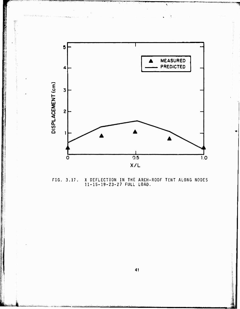
FIG. 3.17. X DEFLECTION IN THE ARCH-ROOF TENT ALONG NODES 11-15-19-23-27 FULL LOAD.
41
Büafcii k *f^i>fft*t£k, ■iput-WtAU^: J..^ ^., . ■>:,. W. *^.^~t..., ,*-. .- -'■ - ■ ..v- jj ^-^fe,^JMü^.i^ ,jifk

MM^^^agBa"t '^-'—~^-7-""T"Tr-r-iT7r'7*-»i-r»——■—T r
"»re*.
"WIUBWW
tent deflection! but in minor changes in predicted frame and fabric stresses for the positions shown. There is generally excellent agreement between predictions and measurements for the arch-roof tent. The major discrepancy occures in the side-to-side bending stress (bending about the Z-axis) in the frame at Node 11 (see Figure 3.12). The exact cause of this discrepancy is difficult to pinpoint; it is more than just a joint efficiency problem, since the stress at the center of a simply supported twam would account only for a factor of 2 over that for the same beam built in at both ends. It is also apparent, from Figure 3.17, that there are some errors in fabric deflection. These errors ultimately result in errors in the load (and the direction of the load) applied to the beam by the fabric, which may account for the discrepancy.
The slant-roof tent predictions and measurements do not agree as well as those of the arch-roof tent The difficulty appears to be primarily in the modeling of the loading. As described in Reference 1, bags filled with lead shot* were laid on the model tent fabric to simulate a snow load. Since the roof angle was large, i.e.,~ 45° from horizontal, the bags tended to slide down the pitch of the roof, resulting in insufficient friction between the bags and the model tent fabric. Numerous techniques to increase the friction (e.g., double-backed tape) were tried without much success. Eventually, a small portion of the bag (about 2 cm of ~ 46 cm) was draped over the ridgepole; the remainder rested on the fabric. Clearly, this arrangement could not simulate exactly the uniform vertical load applied to the computer model of the tent; i.e., the load applied in the plane of the fabric and the load applied to the ridgepole are not properly simulated in the computer by a uniform vertical load. It is believed that this is the source of the prediction errors.
4. FABRIC SLIPPAGE
In previous studies, we dealt with fabric-frame interaction in frame-supported tents as if the fabric were rigidly attached to the frame. In actual practice, however, it is possible for the fabric to slide over the frame. In this section, we report on some preliminary analysis and laboratory testing performed to determine whether it is feasible to model fabric-frame interaction mathematically while allowing for fabric slippage.
4.1 Strip Finite Element With Slippage Capability
To model fabric slippage, we begin with a one-dimensional model of a strip of fabric, i.e., a string. In this model, we will include nonlinear effects caused by large deflections and moderate rotations, as we did with the membrane element in NONFESA (see Reference 2). Figure 4.1 shows a 3-node string element with slippage capabilities.
*Each bag was divided into numerous small compartments to maintain a uniform distribution of lead shot and, hence, of load.
42

»■■' '■■■ rr^TT-ir--^ -r-^— ---■■■'- ■7^'""——r^-—
-*X
FIG. 4.1. STRING SLIPPAGE ELEMENT.
43
fcir-VA*1«*»^. -•■•"->'- ' -:,;j.,;-..,:;.... ,-.... ■ ..^.„^^^v^-.....-,..,,^..;..,,;.:^.^:.^^^!^^.^!;™;

i.«i»^-. -■ -' ....,-ijm.ij.j.u , j „I, in.,.
' **& r-
—MWJwnimiVi^iiPijraimniii »■ —
Slippage occurs at Node 2, where the string element contacts the trame. We assume that there is no friction between the* fabric strip and the frame member, so the resultant force amplitude at Node 1 is epual in magnitude to the issultar.t force amplitude at Node 3.
With these assumptions in mind, *he strain in the element can be written:
dx 2\3x/ e =
L
3u' 1
3x' 2\3x \ ax' •' 14.1)
where u and v are displacements in ihe X and Y-directions of Figure 4.1, u' a::d V. are displacements parallel and perpendicular to the 12 segement of the element, x' is the direction parallel to the 1-2 segment, and L - L, + L2. Rewriting Eq. 4.1 as
Jb.fi 1(*L) LJ ' 2^3x*>
du' 3x'
3v' 3x'
L 1 I 2*. '2 3x
fin dx
Tx~
(4 2)
Defining the derivatives as
3u' u'2~u', ax' L,
dv' _ Va-vi
3x' L,
3u _ u3-u2
3x L2
3v _ V3-V2
3x L, (4.3)
and noting that the geometry in Figure 4.1 and the definitions of u, v, u', imply
u' = u cosö - v sinö
v' = u sinö — v cosö,
—T n ii" -ii • 1 imwiwim
44
SttMM.'HHP.IB.'I'J".",1 mmmaammimiimuammmim

„iiii.jiii_nfif 'mupuji! maapf Vn.i'iiiimjwtJiiiniwwiwr»aniyffliTflMWM'»^."*■ y.i. •mamtaxpy. ' "■' ■ pwamp
we can relate the strains to the nodal displacements i the X- and Y-directions of Figure 4.1 by
'.t
e--1 BTu , (4.4)
where
and
COSÖ
-
u2
U3
U S
V|
v2
J sinö I2L 2 dx'
-d+cosö) + 4 sinö -~ 2 dx
sinö + -1 cose 4^" 2 3x'
sinff 1 cosö 3v' • 2 3x'
1 3v 2 9x
1 3v 2 dx
(4.5)
Using Eq. 4.4 and the relationship between strain e and tension T in the cloth, i.e., T = AEe, we can write the element stiffness matrix [K] as:
[K] = i£ BBT (4.6)
where A is the cross-sectional area of the strip, E is the modulus of elasticity, L = L| + L2, and BB^ is a 6 x 6 symmetric matrix.
45
,-.;> ■■v.-.-;--f.'-.:i.i-.i,:..(>,-

smmm
—
In developing [K], we have included terms to first order in dv/dx end dv'/dx', thus creating a nonlinear element that allows for moderate rotations of segments 1-2 and 2-3. The element is used in an iterative procedure to calculate the displacements and stresses. The solution is begun by setting 8v/dx ■ dv'/dx' - 0 and assembling the resulting element stiffness matrix, along with other element stiffness matrices, into a global stiffness matrix, and solving for the displacements. These new displacements, v3, v2, V|, u», and u,, are used to calculate dv/dx and dvVdx', which are then used to update the stiffness matrix. The stiffness matrix, in turn, is assembled with other elements into a global stiffness matrix and solved again for the displacements. The process is continued until suitable convergence is achieved.
4.2 Experimental Verification of the Fabric Slippage Element
!n this section, we discuss a numbet of the laboratory tests employed to confirm the computer predictions, using the slippage element described in Section 4.1. A number of the assumptions used in developing the element are also examined.
4.2.1 Friction at the Fabric-Frame Interface
One of the assumptions we made in the development or the slippage element in Section 4.1 was that there was negligible friction between the fabric and the frame member at Node 2 (see Figure 4.1). The apparatus shown in Figure 4.2 was used to test this assumption. A strip of 89-gr/m2 (2.6-oz/yd2) typewriter ribbon cloth, 10 cm (4 in.) wide and approximately 61 cm (2 ft) long, was passed over two beams, one rigid, one flexible. The rigid beam, shown in Figure 4.2, was originally a 25-mm-square aluminum beam machined so that the area where the fabric touched the beam was only 6 mm square, the dimension of the frame members in the slant-roof scale-model tent. A flexible beam was simulated by using the jig for obtaining the joint efficiency method with the slant-roof frame test specimen. One end of the fabric was held rigid; a load was applied to the other end. Clamps similar to those described in Reference 1 were used to distribute the load uniformly over the width of the fabric. Fabric stress gauges were installed at two locations on the fabric (positions No. 1 and No. 2, Figure 4.2).
If the interaction between the fabric and the beam were indeed frictionless as postulated, the stresses at positions No. 1 and No. 2 would be identical. Figure 4.3 shows the results of a test program presented in terms of a ratio at the stresses at both positions as a function of the applied load for both the rigid and the flexible beam. Note that the ratio should be 1 for the frictionless case.
46
M^hi- ».i.««1
■i;-t^ii;,\ii.,'J*,'.i.:;^.-
,,>j/yJ..V?. ■*.*'-'« *"*•'■■
-uW'sriiiii .^V. .■,^.^.:,,,1.iajig||i Tfefffctl&ki^i&»^^

- *<•■!■_ »I.^^II.-J.IL»^—•■ ■'■.—■« ■
': ■
i
RIGID ALUMINUM
k8EAM
1-
/
FABRIC STRESS GAUGE " I
T=F
■ FABRIC STRESS GAUGE «2
4 IN. (10 cm) WIDE FABRIC STRIP
FIG. 4.2. FABRIC-FRAME FRICTION TESTING APPARATUS
47
i
1
i

' -- » " "" ' "-
•i&tVBr* ■
m
" o a <
< o o 3 o z z
(0 CO < cc o z
< UJ a: o UJ o
• 0
2S <t ui CD
UJ -J CD
X UJ
-<
^r""'~ \ \ \
<M
\
X\ o
(O
10 o CM
IO o
(N)avoi
w
CM
o
ÜJ to :o <f o
i/i <•> UJ a: I— oo
<_> o •—" a: •
H 03 --~ < et CM £E U- •
rj- CO O CO 1— • UI O a: *—i t—i
O UJ z: uj
m UJ — o =3 Q
C3 O
2 < UJ CD
Q O or
J — -
-. ___, __» <-» •
V
,asll__h______» * _-r»«"*^
\ \
CJ O
or CO CO
- UI or h- co
IO o IO IO
(N)avon
48
< Q UJ
l/l ■—I 00 _l UJ CL. ac a. t- <
U, O O »—< a: -Z. CQ o cc i-. u. i—
(_> u. z: o =>
u. o —' <c h- <t to a: <r.
£.
-ii r ■ -r nrfmMmxwrTrr™""**-*"*-"^- MjWpMWWj WW 1BHH9ÜHI l«Sa»i«»a«^^i^J»a».i^ia^»,.,_,,^.a-i.,J^,„.J ,a.i„JuJjMl

j IM . , ■ I ■■
In the case of the rigid beam, the ratio is considerably different from 1 for both increasing and decreasing load. For increasing load, the stress at location No. 1 is less than that at location No. 2, clearly showing the effects of friction; i.e., friction at the beam-fabric interface takes up some of the load. For decreasing load, friction at the beam-fabric interface results in a higher stress at location No. 1 than would exist if stresses were freely transmitted around the beam; i.e., as the load is induced, friction inhibits the relaxation of the fabric stresses.
The flexible beam shows essentially the same character, except that at higher loads, when the load is increasing, friction seems to have less of an effect. In fact, for loads greater than 5 N, the discrepancy between location No. 1 and location No. 2 is less than 15%. Somehow, the flexibility of the beam decreases the effects of friction. For decreasing load, however, the effects of friction are more pronounced, probably because the deflection in the beam is relieved as the load is decreased, resulting in a stretching of the fabric at location No. 1. Fortunately, our studies are concerned solely with the increasing load case, and the results shown in Figure 4.3 are encouraging.
4.2.2 Laboratory Test of the 1-D String Element
Figure 4.4a shows a simple lab test devised to check out the predictive capabilities of the 1-D string slippage element. The same 10-cm-wide strip of typewriter ribbon cloth used previously is stretched over the beam specimen used to measure the joint efficiency of the joints in the slant-roof tent (Section 2.3). The fabric is held rigid at both ends, and a line load (a weight applied to a rigid beam spanning the width of the fabric) is applied to the fabric. The fabric is slack, so that in the initial unloaded state there is an initial vertical deflection of 4.6 cm at the load point. The fabric stress gauge is attached as shown.
Fibure 4.4b shows the arrangement of the finite-element computer model. Nodes 6-1-2* and 2-3-4 define two string slippage elements and Nodes 5-3 define a beam element (symmetry has been used to simplify the model). The computer code requires a fabric modulus relating fabric tension per unit width to fabric strain. For the test described here, the fabric is stretched uniaxially in the fill direction. In Reference 1, equations relating biaxial fabric tension and strain were d«*'eloped for the fabric. For uniaxial tension, the equations relating fill tension per unit vidth, Tp, to fill strain, ep, reduce to
*ln fact, the fabric is rigidly attached at Node 1. A string slippage element is simply used for convenience. Since the distance from 1 to 6 is short (0.6 cm), any errors introduced by slippage over Node 1 will be small.
49
„,:j,i,a.^LaJa,a^v^.JK,»^,<„.-,i..,,, — »a^"a,J -.^....„^..i.i^j,-,--■■-■ ■>.... jgjj -■ -., ,,-^jte^,.-.. aa^a^«^^

^iM-^Mji »n ■ ■in————mwmm———i"^—SSZ&BtrSg^.
I
LOAD
31cm
BEAM HELDIN JOINT EFFICIENCY
FIXTURE
FABRIC STRESS GAUGE
a) LABORATORY TEST SETUP
LINE OF SYMMETRY
STRING ELEMENTS
b) COMPUTER MODEL
FIG. 4.4. STRING SLIPPAGE ELEMENT TEST
50

'
170 T£ (TF in lb/in.)
or
130 Tp (Tp in N/cm) (4.7)
Using this fabric stress-strain relationship with the string slippage elements in the finite-element model of Figure 4.4b, we obtain the predictions shown in Figure 4.5. Displacements of Node 2 in the Y-direction and the tension per unit width in the fabric* vs the load applied at Node 2, are shown as well as measurements of deflection and stress in the laboratory model.
The stress measurements agree very well with our predictions. Deflection measurements agree quite well with our predictions at the higher loads, but at lower loads (< 4 N) the predictions are higher than measurements. This result is probably produced by inaccuracies in the fabric constitutive relation model at low fabric tensions,''' as well as by the fact that at low fabric tensions the fabric-frame interaction is not completely friction-free (see Section 4.2.1). The deflection of the beam at its center was measured with a dial gauge, but the deflections at maximum load were less than 0.2 mm; consequently, we judge that the gauge accuracy is poor. These deflections, however, are consistent with computer code predictions of beam deflections at maximum load of 0.22 mm in the Y-direction and 0.18 mm in the X-direction.
These results are very encouraging. The very simple friction-free model of fabric slippage has been shown to be capable of predicting fabric stress and deflection with acceptable accuracy, even when the fabric interacts with a flexible frame structure. Our conclusion is that these results make the extension to a two-dimensional fabric slippage element appear to be a feasible, and indeed desireable, next step.
5. RECOMMENDATIONS FOR FURTHER WORK
This report presents the most recent developments h the evolution of the computer code NONFESA. Although the code, in its present state, requires additional Development before it can be used for its ultimate purpose - design and analysis of frame-supported tents - we are close to this goal.
*The tension is constant along the length of the strip.
*Wc have taken no fabric stress-strain measurements below tension of 0.85 N/cm.
51
A™
mmemm

LOAD (N)
FIG. 4.5. COMPARISON OF PREDICTED AND MEASURED FABRIC STRIP DEFLECTION AND TENSION.
52
I *

Ji i^i —■■■!" Hi ^i^mfmmmm
53
In this section, we discuss our recommendations for work needed in four areas to develop and test new capabilities, which will culminate in the comparison of code predictions with the stresses and deflectios measured on a full-scale frame-supported tent under a deadweight load. Areas in which work is needed include:
two-dimensional slippage element
friction correction
scale-model testing
full-scale testing.
Two-Dimensional Slippage Element
With some success, we have developed and tested a one-dimensional string element capable of dealing with slippage over flexible frame elements. But before we can model real tents, a two-dimenlionalal element with similar slippage capability must be developed to model the tent fabric. However, it does appear feasible to develop a quadrilateral element with be a relatively simple extension of the string element presented here. The capabilities of the element should then be checked in a manner analogous to the testing of the string element in section 4.2.
Friction Correction
We have discussed (Section 4.2) how friction, under some circumstances, can have a significant effect on the stresses and deflections on a fabric-frame system when sliding occurs. A useful project would be development of a membrane finite element with sliding capabilities to which an empiriclly derived friction correction could be added, somewhat like a nonlinear joint efficiency. This work would require laboratory testing of the friction that occurs when fabric slides over frame members in order to determine the appropriate parametric dependence of the friction force, i.e., the variance with load, the angle the fabric makes with itself, etc. The two-dimensional slippage element could then be extended to include friction effects. These results would provide a refinement of the friction-free fabric-frame model.
Scale-Model Testing
Once the two-dimensional fabric slippage element is developed, all of the new elements of the code should be combined, and th' code predictions should be compared with measurements on modified versions of the two scale-model tents described in Reference 1.
fe.

1 ■ " ry»rowy-i ■K-."-T«BBl
Figure 5.1 shows a possible configuration for the slant-roof tent This model differs from the eariier scale model in that the fabric is stretched over the frame and held in place with guylines rather than being directly attached to thj frame. The same scale-model frames would be used, unmodified. This testing program could be used to validate the slippage, joint efficiency, and guyline modeling capabilities of the code; it would also provide scale-model data for predicting full-scale results.
Full-Scale Testing
After successful completion of the testing outlined above, we should consider testing the computer code predictions against measurements on a full-scale te.it Prior to exercising the code, the following information will be required:
biaxial stress/strain properties of the tent fabric
detailed frame and fabric geometries
frame joint efficiencies
guyline mechanical properties
guyline pre-tension.
Most of this information has already been obtained in the laboratory for the scale-model tents and therefore should present no special difficulties.
Before full-scale tents are measured, however, some effort must by made to develop means for:
measuring tent and frame deflections
measuring fabric stresses by modifying the existing fabric stress gauges
loading the tent with a uniform deadweight load.
Deflection measurements can be made with dial gauges, micrometer calipers, etc. Stress measurements on the heavy tent fabric can be made with a stiffer version of the existing fabric stress gauge. As for tent loading, something es simple as sandbags could be used, although some means must be developed for applying the shear load (the load in the plane of the fabric) to the fabric. Velcro strip? might prove useful.
Once these tasks, particularly the full-scale testing, are completed successfully, the computer code NONFESA will be a viable tool .or aiding in the design of frame-supported tents.
54
'■..\^t&L.'j^
r^^v-.^v:;. .
.:JL

~3W"«WT»™ ■ I 1
V3|
UNIFORM LOAD
GUYLINE FABRIC
GUYLINE
/;//ty/s/ /////; > >> >/x) >/ >P>>>
FIG. 5.1. SCALE-MODEL TENT TEST CONFIGURATION.
55
i_..8AJf'.. äniijB^-.'AJfeijü.Äfil.i,.