Embed Size (px)
Citation preview

FINITE-ELEMENT ANALYSIS OF A HISTORICAL TRUSS RECONSTRUCTED WITH A TRADITIONAL ALL-WOODEN JOINTS
SAHC2014 – 9th International Conference on
Structural Analysis of Historical Constructions
F. Peña & M. Chávez (eds.)
Mexico City, Mexico, 14–17 October 2014
FINITE-ELEMENT ANALYSIS OF A HISTORICAL TRUSS RECONSTRUCTED WITH A TRADITIONAL ALL-WOODEN
JOINTS
Jan Tippner1, Jaromír Milch1, Václav Sebera1, Jiří Kunecký2, Michal Kloiber2, Miroslav Navrátil2
1 Dpt. of Wood Science, Faculty of Forestry and Wood Technology, Mendel University in Brno, Zemědělská 1, 613 00, Brno, Czech Republic
[email protected] , [email protected] , [email protected] , [email protected]
2 The Institute of Theoretical and Applied Mechanics AS CR, v. v. i., Prosecká 76, 190 00, Prague, Czech [email protected] , [email protected]
Keywords: Wooden Joint, Sub-structural Finite-selement Analysis, Historical Truss
Abstract. The Assessment and design of mechanical behavior of joints used in historical timber constructions such as churches, castles etc., is currently paid a big attention in the Czech Republic. The reasons are a) a high number of such structures in the area central Europe; b) missing information about how certain types of historical joints respond to mechanical loads and how to design them from structural point of view. During reconstructions of valuable timber structures there are requirements for very sensitive approach with respect to cultural value, specific environment conditions and preservation of most of original material. The way to fulfill these requirements is to replace damaged parts of beam members by insertion of a new wooden element with the use of traditional all-wooden joints for joining to original structure. Such approaches call for complex mechanical analysis of structure including joints. This article presents one of the numerical approaches that can be used for assessment of historical structures and all-wood joints used in historical structures – reduction analysis using finite element analysis. Using this approach a part of historical structure is analyzed as truss and the joint part is solved as 3D solid body. The FE model in ANSYS software assumes orthotropic material properties of wood (Norway spruce) and elastic behavior, the contact in joint is flexible-to-flexible and symmetric. Results of the FE analyses show the reduction technique efficiently determines global mechanical behavior of the roof structure of gothic St. James's Church in Brno, Czech Republic as well as detailed stress state of the joint reflecting boundary conditions from truss.

FINITE-ELEMENT ANALYSIS OF A HISTORICAL TRUSS RECONSTRUCTED WITH A TRADITIONAL ALL-WOODEN JOINTS
1 INTRODUCTION
Czech Republic located in the Central Europe is abundant of historical timber structures that are often necessary to renovate due to a biotic and abiotic degradation. The studied roof construction presented in this work belongs to one of the oldest church with cathedral-like disposition in South Moravia region – St. James church that is located in the center of Brno, Czech Republic (Figure 1).
Figure 1: St. James's Church in Brno, Czech republic (source: wikimedia commons)
The roof constructions (Figure 2) has 4 levels and contains various connections among which so-called St. Andrew's crosses are most interesting with respect to presented work. St. Andrew cross was actually double cross that was diagonally spanned over the roof construction and served as longitudinal “stiffener”. Most of the connections in the construction are made only of wood including wooden dowels. The St. James church was established in 1220 in Romanesque style, but it was completely rebuilt into much bigger church in late Gothic style. Throughout the time the church gained a few Renaissance and Baroque elements, but its Gothic character stayed mostly preserved and even emphasized in late 18th century after it was neogothicized. The roof construction is neogothic and is dated into 1724 when it was finished by carpentry master Anton Ebenberger [1]. Currently, the roof construction shows large defects including decayed members and, therefore, renovation is needed.
It is often the case that during a renovation of such constructions, a structural assessment must be carried out. For the analysis of complicated structures such as baroque or Gothic truss roof constructions, it is advantageous to use a numerical approach, namely finite element analysis (FEA), instead of analytical calculations. The advantages of using FEA for such tasks are emphasized even more when connections in a truss must be included in the analysis. The reason is that FEA enables modeling a global beam structure (truss) and 3D solid connection including the contact among connection parts at the same time. Such task is often accomplished by reduction techniques, one of those is commonly known as sub-structuring

FINITE-ELEMENT ANALYSIS OF A HISTORICAL TRUSS RECONSTRUCTED WITH A TRADITIONAL ALL-WOODEN JOINTS
[2]. Reduction techniques are often used when reduction of computation time and detailed stress-state is needed at the same time and can be applied on any material and construction [3, 4, 5].
Figure 2: Truss structure of St. James's Church; left: structure with St. Andrew cross members, right: detail of beam connection
The dowel-like connections in the roof construction of St. James church are usually simple dowels made of oak wood and were inserted with lower moisture content to provide contact with joined parts during its service. For their basic analysis with known boundary conditions, the Johansen theory for single-shear joint can be used, for instance implemented in Eurocode 5 [6, 7]. For more complicated boundary conditions the numerical modeling has to be employed. Review of numerical analyses of such wooden connections covering period from 50's up to late 90's can be found in [8] and thus will be omitted here. More recently, an experimental analysis of wooden composite beam connected by dowels welded into the beam layers by a rotation welding was performed [9]. It was shown that a higher number of dowels affected more the beam stiffness than the ultimate load. The finite element method (FEM) and the boundary element method (BEM) are the most popular numerical methods in the research of wooden joints. It is illustrated by reviews ranging numerical models of joints in years 1990 to 2002 [10, 11]. In terms of dowel joints, there are many FE techniques implemented in many softwares an analyst can currently use, but in fact there are four basic model categories – solid bolt, coupled bolt, spider bolt and no-bolt [12, 13, 14]. Despite the preferences for 3D solid dowels, successful use of beams simulating nail connection was presented in recent study too [15].
2 MATERIALS AND METHODOLOGY
The paper presents a particular output of wider project granted by Czech ministry of culture focused on design and assessment of timber joints used in historical structures [17, 18]. The goal of the project is to test various types of traditional all-wooden joints to laid basic findings to further develop standards for their structural design. With the help
FINITE-ELEMENT ANALYSIS OF A HISTORICAL TRUSS RECONSTRUCTED WITH A TRADITIONAL ALL-WOODEN JOINTS
of experimental testing and detailed 3D solid numerical simulation a number of alternatives of joints is tested at simplified loading conditions. The aim of this paper was to describe real loading of joint corresponding to real function of joint in the roof truss. The restoration of roof construction of St. James church with 139 discovered defects [1] requires hundreds of wooden joints that must be carefully implemented in the construction and, therefore, analyzed beforehand.
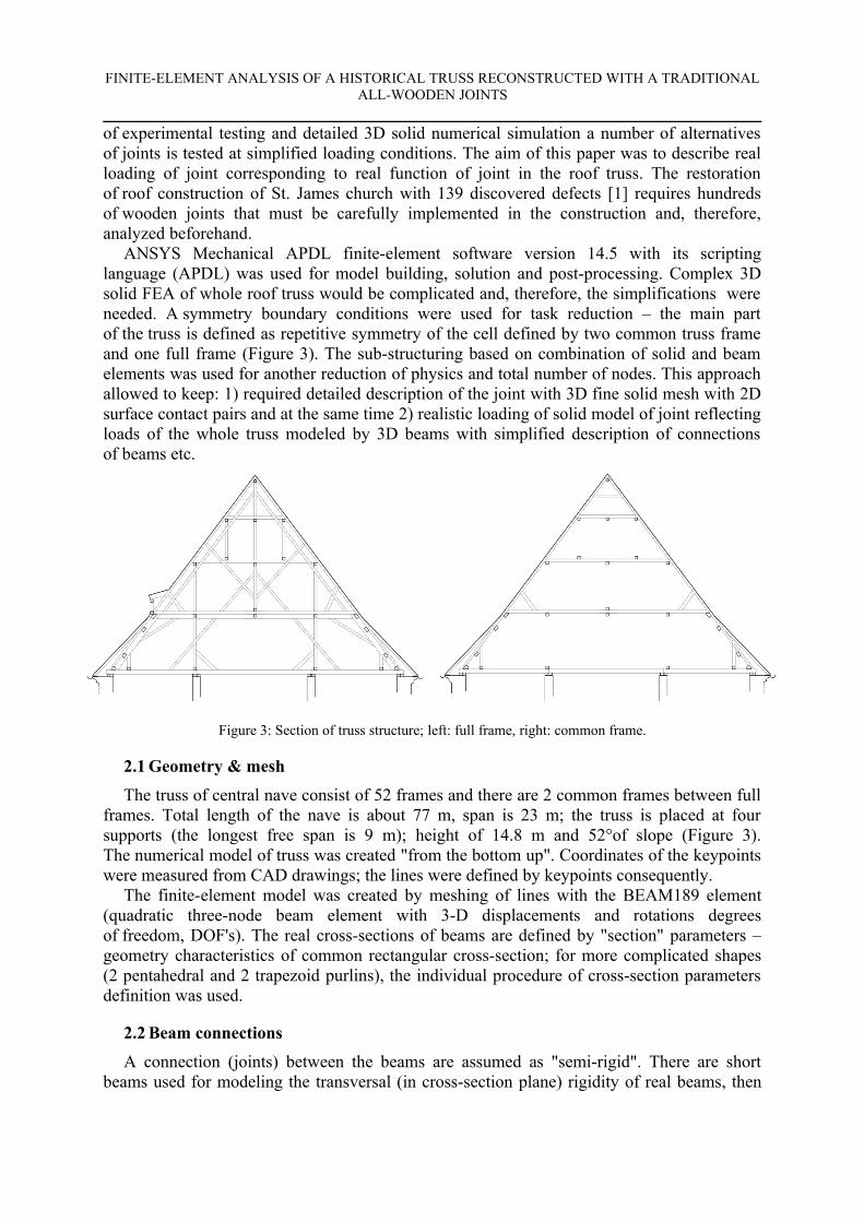
ANSYS Mechanical APDL finite-element software version 14.5 with its scripting language (APDL) was used for model building, solution and post-processing. Complex 3D solid FEA of whole roof truss would be complicated and, therefore, the simplifications were needed. A symmetry boundary conditions were used for task reduction – the main part of the truss is defined as repetitive symmetry of the cell defined by two common truss frame and one full frame (Figure 3). The sub-structuring based on combination of solid and beam elements was used for another reduction of physics and total number of nodes. This approach allowed to keep: 1) required detailed description of the joint with 3D fine solid mesh with 2D surface contact pairs and at the same time 2) realistic loading of solid model of joint reflecting loads of the whole truss modeled by 3D beams with simplified description of connections of beams etc.
Figure 3: Section of truss structure; left: full frame, right: common frame.
2.1 Geometry & mesh
The truss of central nave consist of 52 frames and there are 2 common frames between full frames. Total length of the nave is about 77 m, span is 23 m; the truss is placed at four supports (the longest free span is 9 m); height of 14.8 m and 52°of slope (Figure 3). The numerical model of truss was created "from the bottom up". Coordinates of the keypoints were measured from CAD drawings; the lines were defined by keypoints consequently.
The finite-element model was created by meshing of lines with the BEAM189 element (quadratic three-node beam element with 3-D displacements and rotations degrees of freedom, DOF's). The real cross-sections of beams are defined by "section" parameters – geometry characteristics of common rectangular cross-section; for more complicated shapes (2 pentahedral and 2 trapezoid purlins), the individual procedure of cross-section parameters definition was used.
2.2 Beam connections
A connection (joints) between the beams are assumed as "semi-rigid". There are short beams used for modeling the transversal (in cross-section plane) rigidity of real beams, then

FINITE-ELEMENT ANALYSIS OF A HISTORICAL TRUSS RECONSTRUCTED WITH A TRADITIONAL ALL-WOODEN JOINTS
the joints (connections between nodes) are modeled with technique called constraint equations (CE). Also a simple connections via shared keypoints or a special elements (COMBIN types) were tested in some parts of truss. CE allowed to define simple linear relationships of DOF's between groups of selected nodes of both connected beams. The displacements and rotations of the first beam in the place of joint are scaled by linear factor/coefficient and then applied to the second beam. A several alternatives of different rigidity of joints (factor for rotations and displacements) was computed.
The model of full frame consist of 234 lines and 68 joints, model of each common frame consist of 61 lines and 19 joints. The frames are connected by longitudinal purlins (21 in total conected via 63 joints). Longitudinal stiffness of all truss is achieved using longitudinal purlins and St. Andrew's crosses. Total count of the beam elements is 3,170; total count of CEs is 438 (for 3 displacements and 3 rotations). The solid sub-model consist of about 50,000 solid elements and about 5,000 contact-target elements.
2.3 Loading & constraining
Load of the truss was applied according to standards EN 1991-1-1, EN 1991-1-3, EN 1991-1-4 [19, 20, 21]. The load consists of self-weight, snow, wind actions and load of roof covering. The frame was loaded using a combination of applied loads - gravity (self-weight), snow and wind load) by the locations of St. James's Church in Brno, Czech Republic. According to maps of wind for Czech Republic, the location belongs to the region of second level of wind load with fundamental wind velocity 25 m∙s-1. According to the maps of snow regions in the Czech Republic, the locations belongs to first zone with characteristic value of snow load on the ground of 0.75 k∙N∙m-2. The self-weight was applied following [19] on all members of frame by definition of gravity acceleration constant of value 9.81 m∙s-2.
Snow load according to [20] depends on the characteristic value of snow load on the ground and angle of slope of roof. The loading by snow was oriented in vertical direction as part of resultant force on nodes of beam. The wind load according to [21] was applied for gable slope roof type. This type consists of five differently loaded faces. Peak velocity pressure was based on fundamental wind velocity. The wind pressure was applied as nodal forces in two directions – vertically and horizontally. The roof cladding is represented by wooden decking (25 mm) with cooper plate. The load by roof cladding was oriented in vertical direction. Symmetry conditions were set to all marginal nodes of longitudinal purlins and Andrew's crosses.
2.4 Sub-structuring
The principle of substructuring was used to allow detailed 3D solid & contact modeling of the wooden joint with corresponding loading coming from simplified beam structure of whole truss. A part of the historical structure is analyzed as beam truss, whereas the joint part is solved as 3D solid body. A detailed 3D solid model of joint was implemented at different positions to the roof. The 3D solid joint was inserted into the truss with use of a contact pair with a "master node". Specific contact element types were used (CONTA 175 and TARGE170). The surface-based constraint type of contact pair was created between end of the beam (keypoint) and the solid model (area).
The solid FE model of the joint with oblique faces and dowel uses a regular sweep mesh with quadratic hexahedral solid elements (SOLID186) in all domains. The interaction between parts of joint was defined by symmetric contact pairs using contact (CONTA 174) and target (TARGE170) elements on the surfaces. The contact algorithm used in computation

FINITE-ELEMENT ANALYSIS OF A HISTORICAL TRUSS RECONSTRUCTED WITH A TRADITIONAL ALL-WOODEN JOINTS
was the augmented Lagrange method. The FE mesh was locally refined at positions with high potential of contact, ie. around the dowel and at oblique faces. To obtain a convergence of the task, the dowel had to be constrained (glued) to one part of the joint.
Figure 4: FE model of 3D beam truss with 3D solid joint in ANSYS. Illustrating of constraining and loading by force components, red points represent the keypoints with defined symmetry condition.
2.5 Material
Material model of 3-D beams and detailed 3-D solids was based on the elastic orthotropic properties of Norway spruce according to the literature data from the region [16] and is given by Table I. The material of dowel had rotated coordinate system at 90° to beam longitudinal and was defined also as Spruce.
Table I. Used Orthotropic material model of Norway Spruce (Picea abies L.) - adopted from [16].

FINITE-ELEMENT ANALYSIS OF A HISTORICAL TRUSS RECONSTRUCTED WITH A TRADITIONAL ALL-WOODEN JOINTS
3 RESULTS AND ANALYSIS
Linear static analysis was used to describe behavior of whole truss. Nonlinear large displacement contact analyses were performed to compute displacements, strains, stresses and reaction forces in substructured 3D solid model of the joint. In Fig. 5, a response to defined loads is plotted in terms of the vertical displacement (UY) of the truss structure where only beam elements are considered.
Figure 5: Nodal solution of vertical displacement (UY) of beam truss; left – global view, right – detail on st. Andrew's crosses. (displacement is magnified 200x; 3D visualization of shape of beam elements based on real
parameters of cross - sections).
The beam model allows to plot full cross-sections of the beam 3D structure. Fig. 5 indicates that windward part of the structure is bend inside the truss, the leeward side is bend rather out of the structure. Beside that, we see that bottom most horizontal beams are deflected the most. This tells these parts should be of concern for detailed analyses for instance using proposed substructuring technique in case of restoration of the construction.
Fig. 6 shows the differences of reaction of truss to loading when the different rigidities of joints are embodied. The definition of beam joints by CE allowed the proportional changes of rigidities in displacements and rotations separately.
The change of rigidity of the joints induces the changes in general behavior of the truss model (moving of max. and min. displacements, changes in displacements in all directions) but the changes in objective vertical displacements are not high. The calculated vertical displacement of 1.93 mm in the middle of Tie-beam in the first level of the truss (Fig. 6a) was about only 2% lower in the case of fully rigid joints than in the case of semi-rigid joints that were set to 100% rigidity in displacements and 50% in rotations. For the most compliance case of 80% displacement rigidity and 50% rotatory rigidity, the difference was not more than 7%.

FINITE-ELEMENT ANALYSIS OF A HISTORICAL TRUSS RECONSTRUCTED WITH A TRADITIONAL ALL-WOODEN JOINTS
a) b)
c) d)
Figure 6: Nodal solution of vertical displacements (displacements are magnified 200x; visualization of beams based on real parameters of cross-sections); a) fully rigid joints - 100% in displacements & 100%
in rotations, b) semi rigid joints - 100% in displacements & 50 % in rotations, c) 80% & 50%, d) 80% & 20%.
In general, small changes in behavior of the truss with different rigidity of joints achieves a very good design of the truss with appropriate structural function of wooden members. Minor changes in other directions of displacement were found as well as changes in distribution of displacements in all truss.
When the reconstruction requires the positioning of the joints to the new positions then the different behavior of truss occurs. The needs of new joint in truss arises in the case of partial replacement of wooden element e.g. the replacement of a half of Tie-beam (one new joint has to be designed) or the replacement of a part in the middle of length of beam (two new joints have to be designed). Both mentioned case were simulated.

FINITE-ELEMENT ANALYSIS OF A HISTORICAL TRUSS RECONSTRUCTED WITH A TRADITIONAL ALL-WOODEN JOINTS
a) b)
c) d)
Figure 7: Nodal solution of displacements (in vertical direction - y) of beam truss with solid joints (displacements magnified 200x); a) to d) different positions of joint in the truss.
If the certain location of the truss resulted in deflection pointing upwards, the FE solid model of joint inserted into this location was flipped upside down to prevent its ease opening. This occurred at positions in the middle of bottom and first level of the truss (Fig. 7a and 7c).
Figure 8: Detailed description of vertical displacements of 3D solid model of joint; left – element solution of elastic strain in longitudinal axis of beam, correct orientation in respect to load direction, right - nodal solution
of displacement in transversal direction - incorrect orientation to load inducing opening of joint.
Figure 8 illustrates the differences between the case of correct orientation (the stresses/strains are distributed through contact areas) and incorrect orientation (insufficient coupling of contact areas causing opening of joint in all directions).
FINITE-ELEMENT ANALYSIS OF A HISTORICAL TRUSS RECONSTRUCTED WITH A TRADITIONAL ALL-WOODEN JOINTS
Results also indicate that due to complicated structure and transfer of moments and forces, several beams are also loaded in torsion. The beams that would have to be replaced in case of restoration, should then have been adjusted to this loading location. This means that in case of joint, it would be more convenient to use joint with more dowels or to develop a different geometry of the joint.
4 CONCLUSIONS
The finite element analysis was used to predict the behavior of whole roof structure and to describe sensitivity of computed outputs (displacements) on parameter of beams and joints (e.g. rigidity of joints). The structure and joints were modeled using a reduction technique of modeling. Such approach can be considered as convenient because is allows both detailed 3D solid & contact modeling of the wooden joint and global truss modeling that imposed boundary conditions to the 3D model.
Using symmetry, the whole structure could be modeled by two types of frames: a) one full frame and b) two common frames. The latter exhibited much lower stiffness. The global truss revealed local displacements, so at certain positions in the truss, the 3D solid FE models of joints had to be flipped upside down to assure joint correct functioning.
Results revealed the different joint's behavior at different positions in truss (e.g. middle vs. side, different levels). This supports the idea that each connection should be adapted to the particular conditions in the truss, restoration eventually. Because of the bending loading of the longitudinal purlins, the joints located nearby are loaded by torque that may be inconvenient due to joint intended purpose.
The global behavior of such complicated truss is even more complex because the original truss was “designed” in a way that tried to eliminate connections as much as possible. Nonetheless, any joint inserted into the truss structure changes its global behavior in nonoriginal and not planned way.
5 ACKNOWLEDGMENTS
This paper was created with a financial support from grant project DF12P01OVV004 “Design and Assessment of Timber Joints of Historical Structures”, NAKI program, provided by the Ministry of Culture of the Czech Republic.
REFERENCES
[1] M. Navrátil, Průvodní zpráva k technologickým postupům oprav a sanace poškozených dřevěných částí krovu (in Czech). Brno. 2013.
[2] Ansys 14.5 Refence manual. 2014.[3] A. De Luca, E. Mele, J. Molina, G. Verzeletti, A.V. Pinto. Base isolation for retrofitting
historic buildings, Evaluation of seismic performance through experimental investigation. 30 (8), 1125-1145, 2001.
[4] C.F. Ferreira, D. D’Ayala, J.L.F. Cabo, R. Díez. Numerical Modelling of Historic Vaulted Timber Structures. Advanced Materials Research, vol. 778, 517-525, 2013.

FINITE-ELEMENT ANALYSIS OF A HISTORICAL TRUSS RECONSTRUCTED WITH A TRADITIONAL ALL-WOODEN JOINTS
[5] C.F. Ferreira, D. D’Ayala, Numerical modelling and structural analysis of historical ecclesiastical buildings in Peru for seismic retrofitting. Proc. SAHC 2012, Wroclaw, Poland. 2012.
[6] K.W. Johansen, Theory of timber connections. International Association of Bridge and Structural Engineering Publications, vol. 9, 249–62, 1949.
[7] Eurocode 5 Design of timber structures. CEN. 2004.[8] M. Patton-Mallory, P. Pellicane, F. Smith, Modeling Bolted Connections in Wood:
Review, J. Struct. Eng., 123 (8), 1054–1062, 1997.[9] C. O'Loinsigh, M. Oudjene, H. Ait-Aider, P. Fanning, A. Pizzi, E. Shotton, E.M.
Meghlat. Experimental study of timber-to-timber composite beam using welded-through wood dowels. Construction and Building Materials, 36, 245-250, 2012.
[10] J. Mackerle, Fastening and joining – finite-element and boundary-element analyses – a bibliography (1992-1994). Finite elements in analysis and design, 20, 205-215, 1995.
[11] J. Mackerle, Finite element analyses in wood research: a bibliography. Wood Science and Technology, 39, 579-600, 2005.
[12] M. Patton-Mallory, Improving analysis of bolted wood connections: a three-dimensional model. 15th Struct Cong., Portland, New York. ASCE, 934–938, 1997.
[13] M. Patton-Mallory, F. Smith, P. Pellicane, Modeling Bolted Connections in Wood: A Three-Dimensional Finite-Element Approach. Journal of Testing and Evaluation, 26(2), 115–124, 1998.
[14] J. Kim, J. Yoon, B. Kang. Finite element analysis and modeling of structure with bolted joints. Applied mathematical modeling, 31, 895-911, 2007.
[15] E.M. Meghlat, M. Oudjene, H. Ait-Aider, J.L. Batoz, A new approach to model nailed and screwed timber joints using the finite element method. Construction and Building Materials, 41, 263–269, 2013.
[16] A. Požgaj, D. Chovanec, S. Kurjatko, M. Babiak, Štruktůra a vlastnosti dreva (in Slovak). Príroda, Bratislava , 1997.
[17] K. Šobra, P. Fajman, J. Máca, Experimental and numerical analysis of vertical splice skew joint with key. Proceedings of the 3rd Conference Nano and Macro Mechanics NMM 2012, 231-236, 2012.
[18] K. Šobra, P. Fajman, Influence of the design parameters on the response of the step skew joint with a key. Engineering Mechanics, 591-595, 2013.
[19] EN 1991-1-1. Eurocode 1: Actions on structures, Part 1-1 General actions - Densities, self-weight, imposed loads for buildings, 2004.
[20] EN 1991-1-3. Eurocode 1: Actions on structures, Part 1-3 General actions - Snow loads, 2004.
[21] EN 1991-1-4. Eurocode 1: Actions on structures, Part 1-3 General actions - Wind actions, 2004.